
High-performance tricolored white lighting electroluminescent devices integrated with environmentally benign quantum dots†
Chang-Yeol
Han‡
,
Suk-Young
Yoon‡
,
Sun-Hyoung
Lee
,
Seung-Won
Song
,
Dae-Yeon
Jo
,
Jung-Ho
Jo
,
Hyun-Min
Kim
,
Hyun-Sik
Kim
* and
Heesun
Yang
 *
*
Department of Materials Science and Engineering, Hongik University, Seoul 04066, Republic of Korea. E-mail: hyunsik.kim@hongik.ac.kr; hyang@hongik.ac.kr
First published on 5th January 2021
Abstract
The electroluminescent (EL) performances of quantum dot-light-emitting diodes (QLEDs) based on either high-quality CdSe- or Cd-free quantum dots (QDs) have been greatly improved during the last decade, exclusively aiming at monochromatic devices for display applications. Meanwhile, work on white lighting QLEDs integrated particularly with Cd-free QDs remains highly underdeveloped. In this work, the solution-processed fabrication of tricolored white lighting QLEDs comprising three environmentally benign primary color emitters of II–VI blue and green ZnSeTe and I–III–VI red Zn–Cu–In–S (ZCIS) QDs is explored. The emitting layer (EML) consists of two different QD layers stacked on top of the other with an ultrathin ZnMgO nanoparticle buffer layer inserted in the middle, with both blue and green QDs mixed in one layer, and red QDs placed in a separate layer. The stacking order of the bilayered EML architecture is found to control the exciton recombination zone and thus crucially determine the EL performance of the device. The optimal tricolored white device yields outstanding EL performances such as 5461 cd m−2 luminance, 5.8% external quantum efficiency, and 8.4 lm W−1 power efficiency, along with a near-ideal color rendering index of 95, corresponding to the record quantities reported among Cd-free white lighting QLEDs.
New conceptsA great deal of effort on the fabrication of quantum dot-light-emitting diodes (QLEDs) using either high-quality CdSe- or Cd-free (mostly InP) quantum dots (QDs) has been dedicated to the monochromatic devices exclusively for high-color reproducibility display applications, while research on white QLEDs for lighting applications remains in a nearly uncharted realm with only limited cases reported to date. Though high-efficiency white QLEDs with different emitting layer (EML) structures (e.g., random mixing, sequential stacking, or tandem) with multiple-colored QDs have been demonstrated earlier, they not only commonly exploited CdSe-based QD emitters but focused on white emissivity mostly for wide color gamut display applications. Meanwhile, the fabrication of white QLEDs as lighting devices was recently implemented by adopting Cd-free I–III–VI QDs, but their device performances were only modest. Herein, based on the novel combination of three environmentally benign primary color emitters of blue and green ZnSeTe and red Zn–Cu–In–S QDs, we explore the solution-processed fabrication of tricolored white lighting QLEDs with a unique bilayered EML architecture. The tricolored white device displays record-high performances (i.e., 5461 cd m−2 luminance, 5.8% external quantum efficiency, and 95 color rendering index) among Cd-free white lighting QLEDs to date. |
Introduction
Emerging technologies related to quantum dots (QDs), from materials synthesis to device applications, have been dramatically improved primarily by making the best use of their attractive characteristics such as tunable band gap and solution processability. In particular, there have been significant advances in the QDs for light-emitting devices where the control over the emission color via a simple adjustment of size and/or composition is a great advantage. In the early stage of research, QDs suffered from poor stability and inferior photoluminescence (PL) characteristics of low PL quantum yield (QY) and broad emission bandwidth. However, such critical problems have been resolved by means of the adoption of a rationally designed core/shell heterostructure together with the appropriate development of the synthetic protocol, allowing them to be utilized in commercial applications.1 As a result, QD-based display panels have been successfully mass-produced by combining a film, where color-converting QDs (as red and green emitters) are embedded, and blue light-emitting diodes (LEDs) in a liquid crystal display (LCD). Besides, there has been much progress in self-emissive or electrically-driven QLEDs for a next-generation QD-based display. The external quantum efficiencies (EQEs) of red (R),2 green (G),3 and blue (B)4 monochromatic QLEDs have already reached the theoretical maximum of 20% via QD materials’ quality control and the optimized multilayered device structure,1–5 although the QDs incorporated in such devices commonly contained a highly harmful substance of Cd, use of which should be strictly restricted in accordance with the global environmental regulation. Thus, subsequent development of efficient and bright QLEDs based on Cd-free compositions including InP,6–9 ZnSeTe,10–13 and Cu–In–S (CIS)14,15 has been pursued, taking full advantage of theoretical and technological knowledge acquired from the precedent CdSe QD-based devices.Whereas a great deal of effort on QLED fabrication has been dedicated to the monochromatic devices exclusively for display applications, work on white QLEDs as lighting devices is very limited and remains relatively underdeveloped in terms of both QD material and device structure. A few designs in QD emitting layer (EML) for realizing white QLEDs have been suggested. The simplest way toward white emissivity is to deposit a single EML where different colored QDs with an appropriate ratio are randomly mixed.16–18 When blue and yellow QDs were integrated in the dichromatic EML of a white QLED, its color rendering index (CRI) was only 14. Once green and red QDs were additionally employed for the formation of a tetrachromatic EML, the resulting CRI increased sharply to 92 owing to their effective filling of the substantial visible spectral gaps produced from color mixing of blue and yellow QDs only.16 Similarly, Lee et al. reported anther white QLED with a tricolored (red, green, and blue) QD-mixed EML, where the electroluminescence (EL) spectral contributions from red, green, and blue QDs were found to be dependent on the driving voltage, attributable to charge migrations among different-colored QDs under an electric field.17 A sequential stacking of QD multilayers was also attempted as a different EML design toward white emissivity.19,20 When the QD multilayers are generated via all-solution processing, damaging or intermixing the underlying EML while stacking another one on top is inevitable. To resolve this issue, therefore, an ultrathin (ca. 3 nm) ZnO nanoparticle (NP) layer was inserted between different-colored QD EMLs, rendering the successively deposited QD multilayers intact. Specifically, the white device with sequentially stacked B/G/R QD EMLs, where two in-between ZnO NP buffer layers were properly placed, exhibited 16![[thin space (1/6-em)]](https://www.rsc.org/images/entities/char_2009.gif) 241 cd m−2 in luminance and 6.8% in EQE.19 Recently, a tandem structure was adopted for the fabrication of white QLEDs, where three R/G/B units were separated by appropriate interconnecting layers.21–23 The best tandem white QLED possessed outstanding EL performances of 115000 cd m−2 in luminance and 27.3% in EQE.22 This tandem white QLED displayed an exceptional color gamut of 124% relative to the National Television Systems Committee (NTSC) standard when combined with commercial color filters. All of the white QLEDs aforementioned that mostly target the display application commonly exploit sharp-emissivity CdSe-based QDs.
241 cd m−2 in luminance and 6.8% in EQE.19 Recently, a tandem structure was adopted for the fabrication of white QLEDs, where three R/G/B units were separated by appropriate interconnecting layers.21–23 The best tandem white QLED possessed outstanding EL performances of 115000 cd m−2 in luminance and 27.3% in EQE.22 This tandem white QLED displayed an exceptional color gamut of 124% relative to the National Television Systems Committee (NTSC) standard when combined with commercial color filters. All of the white QLEDs aforementioned that mostly target the display application commonly exploit sharp-emissivity CdSe-based QDs.
For lighting applications that require a sufficient visible spectral coverage for high color rendering property, Cd-free QDs with a typically broader emission bandwidth than CdSe-based ones have been utilized for the fabrication of white QLEDs. However, progress on white lighting QLEDs comprising multiple-colored Cd-free QDs is tardy particularly due to the scarcity of blue Cd-free QDs. Alternatively, single types of undoped or doped Cd-free QDs, whose emission can cover the whole visible territory, have been tested as a white emissive EML.24–26 For instance, wide visible (blue-to-red)-covering Cu–Ga–S QDs were integrated into a multilayered QLED and the resulting white lighting device produced modest EL outcomes up to 1007 cd m−2 (in luminance) and 1.9% (in EQE) along with high CRI up to 88.24 Later, on the basis of the development of new Cd-free blue QDs of Zn–Cu–Ga–S (ZCGS)25,27 the fabrication of a white QLED was implemented by generating a dichromatic EML, where blue ZCGS plus yellow CIS QDs were randomly mixed with an optimal ratio toward white spectral balance, exhibiting luminance of 2172 cd m−2, EQE of 4.6%, and CRI of 82.27 In this work, we demonstrate solution-processed fabrication of all Cd-free QD-based tricolored (blue, green, and red) white lighting devices with record-high EL performances in luminance, efficiency, and CRI. High-quality ZnSeTe QDs (for blue and green) and Zn–Cu–In–S (ZCIS) QDs (for red) are adopted for EML formation. The EML architecture is designed to have two different QD layers stacked on top of the other, while both blue and green QDs are mixed in one layer and red QDs are placed in a separate layer. EL outcomes are observed to be distinctly dependent on the stacking order of this bilayered EML structure. White QLEDs with a suitable bilayered QD EML, i.e., blue & green ZnSeTe QDs/red ZCIS QDs, yield exceptional device performances of 5461 cd m−2 in luminance, 8.4 lm W−1 in power efficiency, 5.8% in EQE, and 95 in CRI.
Results and discussion
Cd-free ternary ZnSeTe QDs can possess a fine emission tunabiliy in the blue-to-green color via a precise control of the Te/Se ratio in their synthesis, even though the red color is unlikely to be achieved due to the band gap bowing between ZnSe and ZnTe. A large difference in the Te/Se feed molar ratio in ZnSeTe core synthesis (0.0235 for blue and 0.2352 for green cores, see Experimental section in the ESI†) led to two distinct emission colours of blue and green that peaked at 448 and 510 nm, respectively (Fig. 1a), after being elaborately triple-shelled with ZnSe/ZnSeS/ZnS. Such a multishell scheme was designed to mitigate the lattice mismatch-induced interfacial strains at core-to-shell and shell-to-shell, while rendering the exciton confinement effective by means of the formation of the stepwise type-I energetic potentials.11,13 As a result, blue and green ZnSeTe/ZnSe/ZnSeS/ZnS core/shell QDs displayed high PL QYs of 86 and 81%, respectively. The PL bandwidths of the blue and green ZnSeTe QDs were notably different, showing 26 and 48 nm, respectively. A substantial difference in ionic size between Se and Te, by which a certain type of lattice defect in ZnSeTe QDs that likely accompanies the related defect emission(s) can be generated albeit still veiled, is at least one of the factors to give rise to PL broadening.10,11 In this sense, a higher concentration of lattice defects is expected to be present in Te-richer green ZnSeTe QDs relative to Te-less blue ones (refer to Fig. S1a and b (ESI†) for energy dispersive X-ray spectrometer (EDS)-based actual elemental compositions of blue and green cores), leading to a broader PL from the former versus the latter. As shown in time-resolved PL decay profiles (measured from a QD film state), the average lifetime (τavg) (47.8 ns) of green QDs was somewhat longer than that (36.3 ns) of its blue counterparts (Fig. S2a and b, ESI†) presumably due to the presence of more defects in the former relative to the latter ones, being in line with the above PL bandwidth results. Considering the difficulty in realizing red emission from ZnSeTe composition-based QDs (as aforementioned) plus the ultimate demonstration of all Cd-free QD-based high-CRI white lighting EL devices, environmentally benign ZCIS QDs with a broad emissivity were synthesized as red emitters (refer to Fig. S1c (ESI†) for elemental compositions of red cores). Red ZCIS/ZnS QDs with a peak wavelength of 625 nm and a PL QY of 75% exhibited an extensive spectral coverage of a PL bandwidth of 131 nm (Fig. 1a). Such a broad PL stems from the nonexcitonic transition, where photogenerated charges are radiatively recombined via in-gap defect levels such as acceptor (e.g., Cu vacancy) and/or donor states (e.g., In vacancy and/or antisites).27,28 Compared to blue and green ZnSeTe QDs, the τavg (478.2 ns) of ZCIS QDs was very long (Fig. S2c, ESI†) due to their entirely defect-associated recombination nature. As recognized from Fig. 1a, the color combination of these RGB QDs with relevant peak wavelengths can produce white emission having a full visible spectral coverage toward high CRI. The average particle sizes of blue, green, and red QDs were estimated to be 10.2, 8.5, and 6.8 nm, respectively, from high-resolution transmission electron microscopic (TEM) images in Fig. 1b–d. Based on a series of TEM images of blue, green, and red QDs with shelling stage, the average diameter and shell thickness values were also specified in Fig. S3 (ESI†). In particular, the size disparity between blue versus green ZnSeTe/ZnSe/ZnSeS/ZnS QDs is ascribable to different temperatures for core growth and shelling. That is, a higher reaction temperature (300 °C) for blue QDs compared to green ones (270 °C) would naturally lead to a larger core and thicker multishells. Employing the above RGB QDs, multilayered monochromatic QLEDs having an identical device structure of indium tin oxide (ITO) anode/poly(ethylenedioxythiophene):polystyrenesulfonate (PEDOT:PSS) hole injection layer (HIL)/poly(9-vinylcarbazole) (PVK) hole transport layer (HTL)/QDs EML/ZnMgO NP electron transporting layer (ETL)/Al cathode were individually fabricated via all-solution-processing, i.e., sequential spin-depositions of each functional layer. As summarized in Fig. S4 (ESI†), the QLEDs exhibited outstanding EL performances up to 2565, 14504, and 2099 cd m−2 in luminance and 5.2, 8.0, and 5.3% in EQE for the blue, green, and red device, respectively.
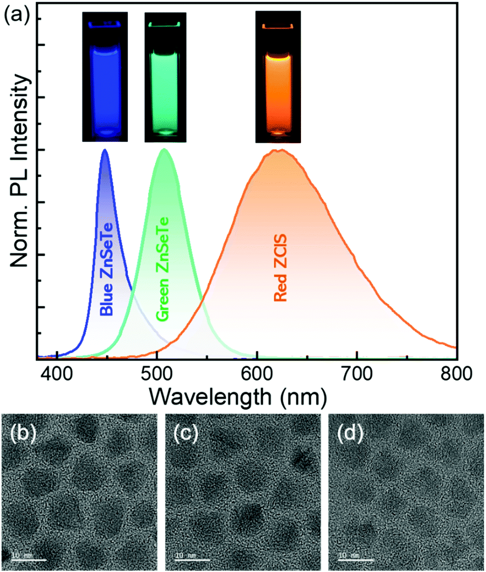 | ||
| Fig. 1 (a) Normalized PL spectra and fluorescent images (insets) of three environmentally benign primary color QD emitters and TEM images of (b) blue and (c) green ZnSeTe core/shell QDs and (d) ZCIS core/shell QDs. The scale bars in (b–d) are 10 nm for all. | ||
The design of the QD EML architecture is one of the important factors in determining device performance of white QLEDs integrated with multiple-colored QDs. Unlike the previous EML configurations of randomly mixed RGB QDs16–18 and sequentially stacked R/G/B QDs19,20 (CdSe-based QDs were commonly used for both cases), a unique EML architecture consisting of both a QDs-mixed EML and stacked multi-EMLs was devised in this work (Fig. 2a). For the QDs-mixed EML, blue and green ZnSeTe/ZnSe/ZnSeS/ZnS QDs were chosen based on their similarities in QD composition, energy band structure, and size among the three RGB QD emitters. The other EML placed below (configuration I) or above the QDs-mixed EML (configuration II) consisted of only red ZCIS/ZnS QDs. In particular, the separation of the lowest-band gap ZCIS QDs from higher-band gap blue and green ZnSeTe QDs in the EML configuration was considered to be conducive to the suppression of undesired inter-QD Förster resonance energy transfer (FRET). For the formation of the QDs-mixed EML, blue and green ZnSeTe QD stock solutions with specified concentrations (Table 1) were blended in three different B:G QD volume ratios (Fig. 2b): 3:1 (blend A), 3:2 (blend B), and 3:3 (blend C). As shown in the PL spectra of the three BG QD blend solutions (Fig. S5, ESI†), the PL intensity of the green emission was intensified. At the same time, that of the blue one was gradually reduced as more green ZnSeTe QD solution was blended with a fixed volume of the blue QD solution. Such a trend was correlated with both the increment of the green ZnSeTe QDs in the blend solution and the reabsorption of emission from larger-band gap QDs by smaller-band gap ones. According to the spectral overlap between the emission of the blue ZnSeTe QDs and the absorption of green QDs (Fig. S6, ESI†), efficient blue light reabsorption by green QDs in the highly concentrated QD blend solution is naturally expected. In order to produce such a unique QD EML structure without damaging the pre-deposited QD layer, a buffer layer was inserted between two QD EMLs. As the buffer layer, we selected ZnMgO NPs instead of the earlier ZnO NPs19 as the former NPs can be advantageous over the latter ones in mitigating the exciton quenching at the interface of the QD EML/buffer layer.29 The protective effect of the ultrathin ZnMgO NP buffer layer was verified through a simple hexane rinsing test presented in Fig. 2c. After the rinsing test the ZCIS QD layer without ZnMgO NP buffer considerably lost its PL intensity, indicative of the easy redissolution of QDs upon hexane exposure, while the PL of the same sample with the buffer atop was well retained. The identical hexane rinsing test on two blue and green ZnSeTe QDs-mixed films (prepared from blend A) in the presence of the buffer also showed little drop in PL intensity. These results clearly demonstrate that the ultrathin ZnMgO NP buffer could effectively protect the underlying QD layer during the fabrication of the stacked EML structure. The surface roughness of the blue and green QDs-mixed layer without versus with ZnMgO NP buffer was further evaluated by atomic force microscopy (AFM) in an effort to provide evidence of the existence of the buffer atop, showing root-mean-square roughness (Rrms) values of 2.4 and 1.9 nm, respectively (Fig. S7, ESI†). Such reduced Rrms after buffer coating is attributable to the planarization of the rugged (larger-sized) QD layer surface by (small-sized) the ZnMgO NP layer. The presence of the buffer on the QD layer was further verified by X-ray photoelectron spectroscopy (XPS) measurements, where an Mg 1s photoelectron signal was clearly detected (Fig. S8, ESI†). Fig. 2d shows a cross-sectional TEM image of a multilayered QLED with the unique EML structure of blue and green ZnSeTe QDs (bottom)/red ZCIS QDs (top), where the uniform formation of interlayer mixing-free EMLs enabled by the insertion of ZnMgO NP buffer was observed. Thicknesses of individual functional layers were estimated to be 38, 22, 19, and 42 nm for PEDOT:PSS HIL, PVK HTL, QD EMLs, and ZnMgO NP ETL, respectively. The physical presence of ZnMgO NP interlayer was indistinct in Fig. 2d, but its thickness was estimated by a surface profiler to be 3.5 nm, corresponding to about a monolayer.
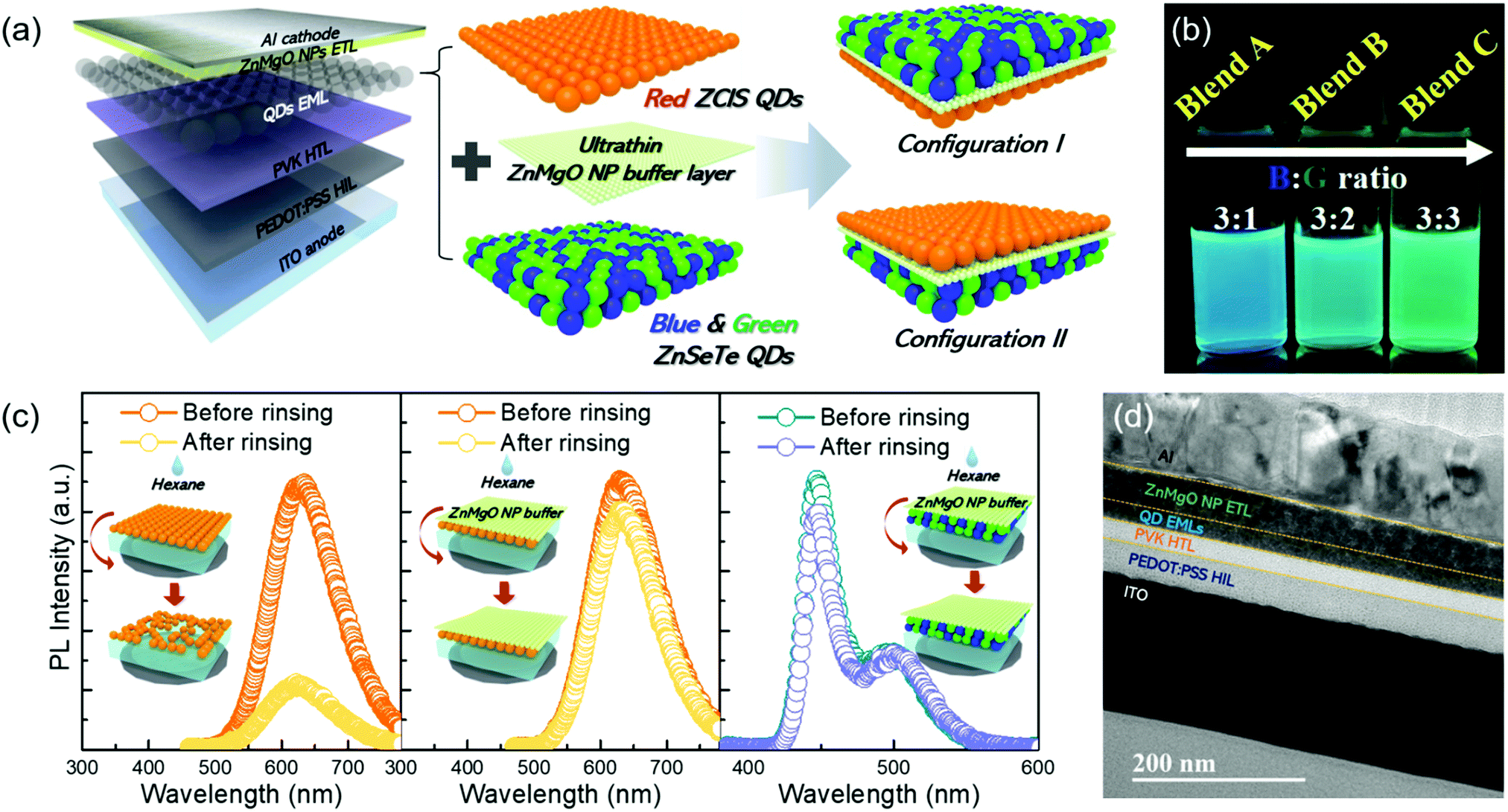 | ||
| Fig. 2 (a) Device schematic of multilayered QLEDs having ZnMgO NP buffer layer-inserted stacked EMLs of a red ZCIS QD layer and blue and green ZnSeTe QDs-mixed layer with different stacking orders (configuration I and II). (b) Fluorescence image of three blend solutions of blue and green ZnSeTe QDs with different B:G volume ratios. (c) Comparison of the PL spectra of the red ZCIS QD film without (left) and with a buffer layer (middle) and the blue and green ZnSeTe QDs-mixed film with a buffer layer before versus after the hexane rinsing test. (d) Representative cross-sectional TEM image of a QLED with an EML structure of blue and green ZnSeTe QDs (bottom)/red ZCIS QD (top). | ||
| Blue ZnSeTe QD | Green ZnSeTe QD | B/G QD weight ratio | ||
|---|---|---|---|---|
| QD stock solution | ||||
| Optical density (@wavelength) | 2.75 (@420 nm) | 2.0 (@450 nm) | — | |
| Weight concentration | 4 mg ml−1 | 7 mg ml−1 | ||
| Blended QD stock solution | ||||
| (blending volumes) | Blend A | 3 ml | 1 ml | 12/7 |
| Blend B | 3 ml | 2 ml | 12/14 | |
| Blend C | 3 ml | 3 ml | 12/21 | |
A bichromatic QLED having the blue and green ZnSeTe QDs-mixed EML only (prepared with blend A in Fig. 2b) was fabricated prior to the tricolored white QLEDs, with the same device structure and processing conditions as in the above monochromatic devices applied. In the case of such an EML mixed with two QDs having different band gaps, the occurrence of FRET between them is unavoidable. According to the PL decay profiles recorded from blue and green ZnSeTe QDs-mixed film (Fig. S9, ESI†), the τavg values of the blue and green ZnSeTe QDs were 16.7 and 54.2 ns, respectively, which was quite differed from those estimated from individual QD films. That is, the τavg of blue QDs measured from the QDs-mixed film was substantially shortened when compared to that from the blue QD film (36.3 → 16.7 ns). On the other hand, the τavg of green QDs in the mixed film was longer than that in the individual QD film (47.8 → 54.2 ns). Such τavg changes in the QDs-mixed film originates from an efficient FRET between the blue and green ZnSeTe QDs acting as the donor and acceptor, respectively.17,21 Meanwhile, the peak luminance of this bichromatic device was 5138 cd m−2 at a driving voltage of 7.5 V (corresponding to 208 mA cm−2 in current density) (Fig. 3a). This intermediate luminance value between those of blue (2565 cd m−2) and green QLEDs (14504 cd m−2) is ascribable largely to the different relative sensitivity factors of human vision on a given emission spectrum (i.e., a much higher eye sensitivity to green versus blue color). Its peak device efficiencies were 8.4 cd A−1 in current efficiency and 6.9% in EQE at a current density of 16.2 mA cm−2 (Fig. 3b). Despite the blue-to-green QD FRET in the QDs-mixed EML aforementioned, the resulting EQE was rather high compared to that (5.2%) of monochromatic blue QLEDs. The green ZnSeTe QDs in the QDs-mixed EML have a higher valence band maximum (VBM) level allowing for a better hole injection from the PVK HTL compared to the blue ones (the detailed device energetic alignments will be also presented in the following Fig. 4). And, the holes injected preferentially into the green QDs can be further energetically transported to the adjacent blue QDs under an electric field. In this regard, green QDs can adjunctively serve as a hole transporting bridge between the HTL and blue QDs. This claim is also in line with the observation that the turn-on voltage of this bichromatic QLED (Fig. 3a) was lower than that of the blue device (Fig. S4a, ESI†) and rather comparable to that of the green one (Fig. S4b, ESI†). As presented in the as-recorded EL spectra with voltage increment (Fig. 3c), both emissions from blue and green QDs appeared to become intensified to a similar extent. However, when the EL spectra were normalized relative to the blue emission, the gradual reduction, albeit slight, of the EL contribution from the green QDs was observed with increasing bias (Fig. 3d). As addressed in the previous RGB CdSe QD-based white EL devices,17 this phenomenon can be rationalized by the field-assisted inter-QD charge migration. As will be stated later (Fig. 4), the facile electron injection from the ETL to the EML, which causes the electrons to be evenly distributed to both blue and green QDs in the EML, is possible as the electron injection barrier at the ETL/EML is negligible. Meanwhile, the hole injection barriers at the HTL/EML are not only large but different for both QDs. Green ZnSeTe QDs with a relatively small hole injection barrier (due to the upshifted VBM level) can receive more holes than the blue QDs do at a low voltage. As the bias increases, the holes in the green QDs are more likely to be migrated by an enhanced electric field to the neighbouring blue QDs. As a consequence, the EL contribution from the green QDs was relatively reduced at increasing voltage. In addition to blend A, blend B and C were also tested for the fabrication of bichromatic QLEDs. Blend B- and C-based bichromatic devices produced the peak values of 5424 and 6001 cd m−2 in luminance and 7.1 and 7.3% in EQE, respectively (Fig. S10, ESI†), showing steadily improved EL outcomes with increasing green QD ratio in the blend.
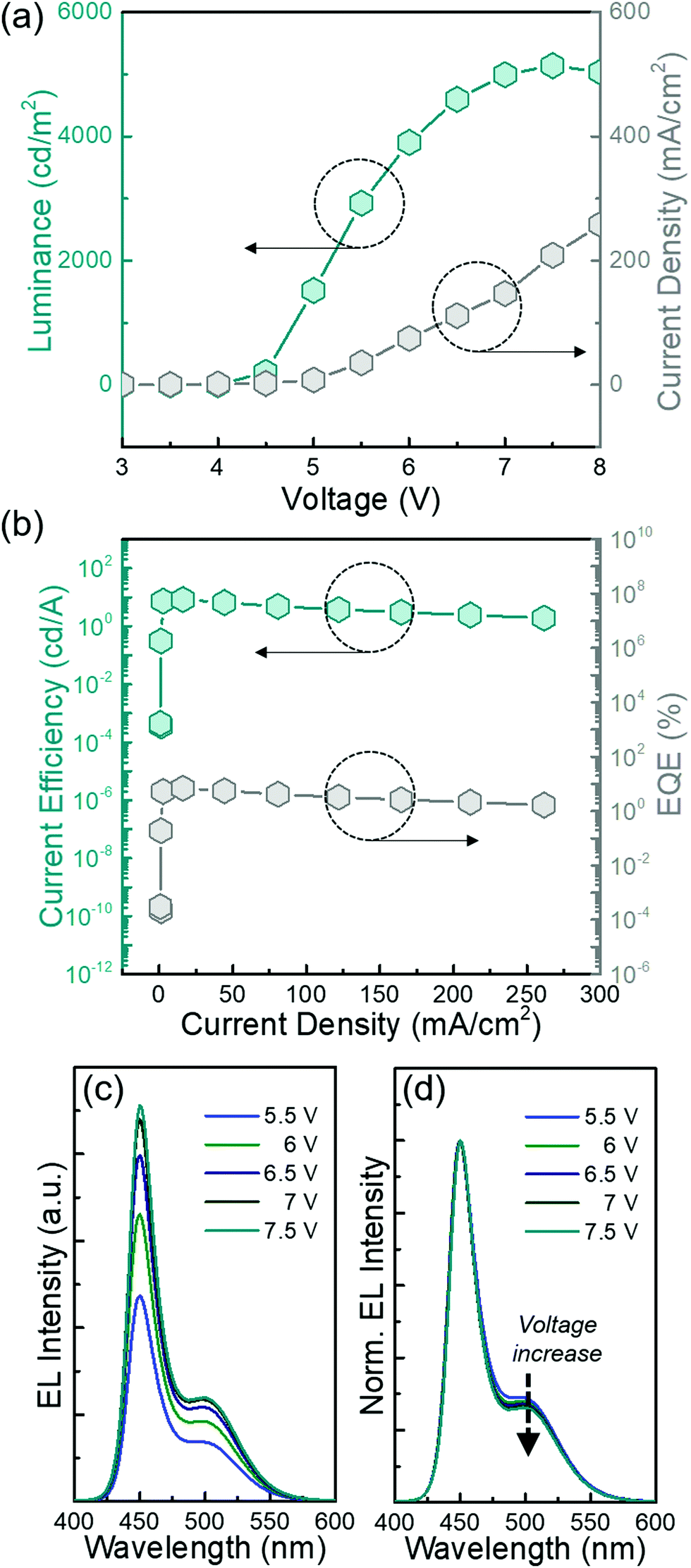 | ||
| Fig. 3 Variations of (a) luminance–current density and (b) current efficiency–EQE as a function of voltage and current density, respectively, and (c) as-recorded and (d) normalized EL spectral evolutions of a blend A-based bichromatic QLED upon increasing voltage. | ||
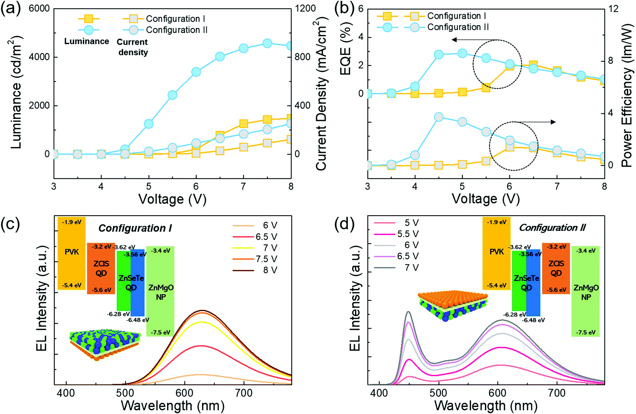 | ||
| Fig. 4 Comparison of EL outcomes of QLEDs with different EML structures of configuration I versus II. (a) Luminance–current density and (b) EQE–power efficiency as a function of voltage. Voltage-dependent EL spectra and corresponding energy band diagrams (insets) of (c) configuration I- and (d) II-based devices. The blue and green ZnSeTe QDs-mixed EML was generated with blend A (B:G = 3:1). | ||
For the following white QLED fabrication, we examined the effects of stacking sequence in the QD EML architecture, i.e., red ZCIS QDs/blue and green ZnSeTe QDs (configuration I), and blue and green ZnSeTe QDs/red ZCIS QDs (configuration II) (Fig. 2a), on device performance. Note that the above blue and green ZnSeTe QDs-mixed EML was generated with blend A (B:G = 3:1) in Fig. 2b. A ZnMgO NP buffer layer (inserted between two EMLs) having a deep VBM level will in principle establish a too high injection barrier for hole flow from the bottom QD EML to the next top one. Nevertheless, holes are likely to be smoothly tunnelled across the buffer layer with an ultrathin thickness under a high electric field.19 The white QLEDs with configuration I and II exhibited substantially different EL outcomes. As compared in Fig. 4a and b, the peak luminance, EQE, and power efficiency from the configuration I device were only 1525 cd m−2, 2.1%, and 1.4 lm W−1, respectively, while the corresponding peak values from the configuration II device were higher, i.e., 4575 cd m−2, 2.9%, and 3.7 lm W−1. Besides, we observed entirely different EL spectra from the configuration I and II-based QLEDs. Unlike the configuration I where only red emission from the ZCIS QDs appeared (Fig. 4c), a tricolored emission from all the QDs of the EMLs was recorded in the configuration II (Fig. 4d). Changes in the energetic barriers depending on the stacking order of the QD EMLs will affect the flow of electrons and holes across the QD EML, which in turn generates different exciton recombination zones. The energy band diagrams of the QLEDs with different configurations (insets of Fig. 4c and d) were proposed based on the experimental UV photoelectron spectrometer (UPS) and absorption results of blue and green ZnSeTe QDs (Fig. S11 and S12, respectively, ESI†) and the energy levels of red ZCIS/ZnS QDs in the literature.24 As illustrated in the energy band alignment of configuration I, electrons could be readily migrated from the ZnMgO NP ETL to all the QDs in the EMLs due to an insignificant electron injection barrier at the ETL/EMLs. Hole flow from the PVK HTL to the bottom EML of ZCIS QDs was facilitated owing to the in-between small energy hurdle. However, for the holes injected towards the ZnSeTe QDs-mixed layer, the energetic barriers (0.68–0.88 eV) between the EMLs (R/BG) were large enough to interrupt the flow. Thus, few electrons and all holes were confined in the ZCIS QD layer, where excitons were recombined. Meanwhile, in the case of the configuration II-based white QLED, a smooth supply of electrons to all the QDs in the EMLs was also conceivable. There was a large hole injection barrier between the PVK HTL and bottom EML of mixed ZnSeTe QDs. Nevertheless, once the holes were injected into the ZnSeTe QDs-mixed layer, they could energetically readily flow to the adjacent top EML of ZCIS QDs without any hindrances. Since both electrons and holes were distributed over all the QD EMLs (i.e., delocalized exciton recombination zones), tricolored white emission could be successfully produced. Returning to Fig. 4a and b, we also noticed that as compared to configuration I, configuration II led to a notably larger current density, lower turn-on voltage, and lower voltage at the peak efficiencies. This is also in line with the current density–voltage characteristics of electron-only devices (EODs) and hole-only devices (HODs) with different EML configurations, showing similar current densities in EOD for both configurations, but much higher current densities in HOD for configuration II relative to I (Fig. S13, ESI†). All of these results can be understood again by a large disparity in the bottom-to-top EML hole injection barrier between configuration I and II devices.
The above tricolored white EL (Fig. 4d) was not spectrally balanced with the green component highly depressed. Therefore, to demonstrate a better-balanced white spectrum with an augmented green EL contribution, two other BG ZnSeTe QDs-blended solutions of blend B (B:G = 3:2) and blend C (B:G = 3:3) containing higher green QD contents than in blend A (B:G = 3:1) (Fig. 2b) were applied with the configuration II EML design, while the top ZCIS QD EML remained unchanged. As compared in red emission-normalized EL spectra collected at driving voltages corresponding to peak luminances for the individual devices, a systematic increment of the green EL component from blend A to C was indeed observed (Fig. S14, ESI†). Moreover, as the amount of green QDs in the BG QDs-mixed EML increased, the device exhibited gradually improved EL performances. Specifically, when the BG ZnSeTe QD blend was changed in the sequence of A → B → C, the corresponding peak values were 4575 → 5171 → 5461 cd m−2 in luminance, 2.9 → 4.2 → 5.8% in EQE, and 3.7 → 5.9 → 8.4 lm W−1 in power efficiency (Fig. 5a and b). The EQE of QLEDs is expressed as EQE = ηi·ηPL·ηoc, where ηi is the charge balance ratio (i.e., the fraction of injected charges that form excitons), ηPL is the PL QY of QD emitters, and ηoc is the outcoupling efficiency. Reasonably assuming that BG QDs-mixed EMLs from blend A, B, and C have nearly the same ηPL based on similar PL QYs of 86% for blue and 81% for green QDs and the above three white QLEDs having identical ηoc, such a systematic trend in EL performance should be linked with the disparity in charge balance ratio (ηi) among the devices. Taking the higher VBM level of green QDs versus blue ones into account, a higher green QD content in the bottom EML is likely to facilitate the hole injection more, leading to a better charge balance. It is noteworthy that the blend C-based white QLED surely displayed the record values in both luminance and efficiencies among Cd-free QD-based white lighting devices (Table S1, ESI†), surpassing the precedent best one (integrated with I–III–VI-based blue ZCGS and yellow CIS QDs) having a luminance of 2172 cd m−2 and EQE of 4.6%.27 With the prominent green spectral increment of the white EL (Fig. S14, ESI†), its peak CRI was also sharply enhanced from 48 (blend A), 84 (blend B) to 95 (blend C). As seen from the spectral evolution of the representative best-performing blend C-white device, the EL intensities of three distinct RGB emissions appeared to well scale with the applied voltage (Fig. 5c). However, a close spectral inspection through the normalization relative to the blue EL showed the notable depression of the green and red EL components in the overall white spectrum as the voltage increased (Fig. 5d). Gradual, slight reductions of the green EL relative to the blue one with increasing voltage are attributable to the electric field-assisted green-to-blue QD hole migration in the bottom QDs-mixed EML, as described earlier in the bichromatic device. Meanwhile, as compared to the green QD EL, the voltage-dependent reduction of the red EL from ZCIS QDs was rather progressive. Considering that ZCIS QDs exited as a separate top EML and substantial hole injection barriers between the bottom and top EMLs were established (inset of Fig. 4d), the hole migration from red ZCIS to blue and/or green QDs is unlikely to take place. Instead, the in-gap state-involved nonexcitonic transition of ZCIS QDs, inevitably entailing a much longer τavg than the excitonic recombination of ZnSeTe QDs (Fig. S2, ESI†), will be responsible for their relative EL quenching upon increasing voltage. When more charges are injected into QDs under a higher voltage (or current density) driving, Auger deexcitation becomes more efficient due to increasing charge imbalance. Under this situation, Auger deexcitation is expected to occur more efficiently in the QD with longer τavg,11,24,27,30 indicating that long-decaying ZCIS QDs are likely much more prone to Auger deexcitation than shorter-decay ZnSeTe QDs and in turn the former become less competitive in EL gain than the latter under increasing current density. Such a gradual red spectral shrinkage at a higher voltage naturally led to the changes of the Commission Internationale de l’Eclairage (CIE) color coordinates (Fig. 5e) and correlated color temperature (CCT) (Fig. 5f) with white emission from (0.388, 0.385) and 3866 K at 5.5 V to (0.356, 0.360) and 4628 K for 7.5 V, respectively. In spite of the white spectral variation, however, a stable CRI of 95 was fortunately obtainable regardless of voltage (Fig. 5f). This excellent CRI that resulted from a near-perfect spectral balance and coverage from a standpoint of high-color rendering white lighting was definitely the highest value to date among both Cd-containing and Cd-free QD-based white lighting devices (Table S1, ESI†). Lastly, the operational lifetime of the representative device of the blend C-based tricolored white QLED that produced the best EL performances was measured, showing a short half lifetime (T50) of ∼30 min under a constant current density of 1.9 mA cm−2 at an initial luminance of 220 cd m−2 (Fig. S15, ESI†). Further work toward higher-stability as well as higher-efficiency of white QLEDs is under way for their ultimate application as a lighting source.
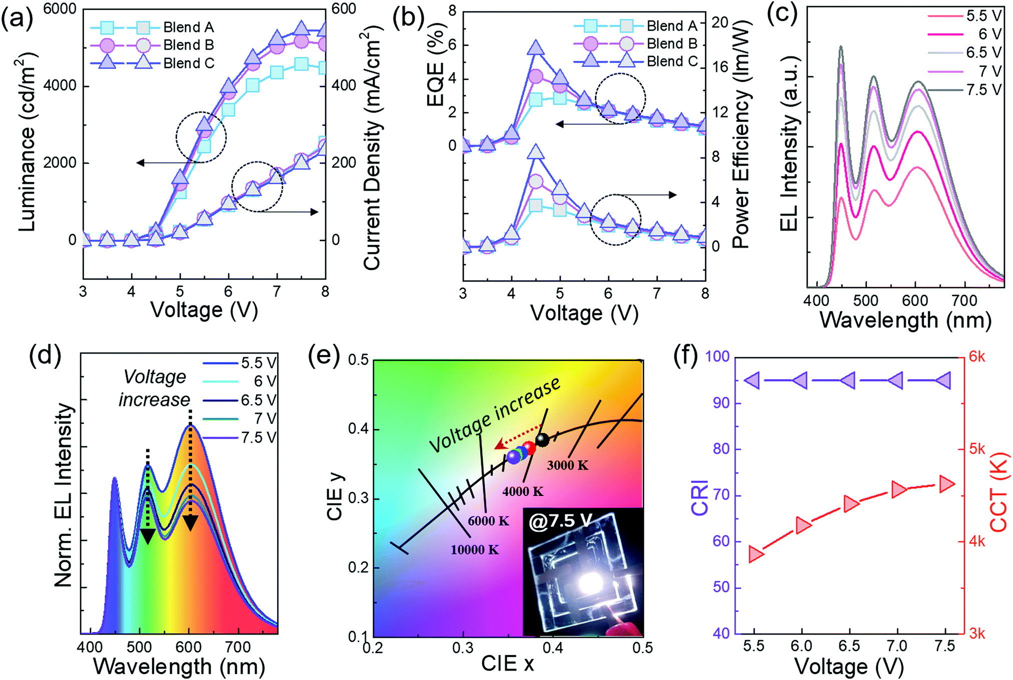 | ||
| Fig. 5 Comparison of voltage-dependent (a) luminance–current density and (b) EQE–power efficiency characteristics of configuration II-based three white QLEDs fabricated with blend A, B versus C. Variations of (c) as-recorded, (d) normalized (relative to the blue emission) EL spectra, (e) CIE color coordinates, and (f) CRI and CCT of the blend C-based tricolored white QLED as a function of voltage. | ||
Conclusions
We first synthesized three primary color Cd-free emitters of blue and green ZnSeTe/ZnSe/ZnSeS/ZnS and red ZCIS/ZnS QDs possessing high PL QYs of 86, 81, and 75%, respectively. These RGB QDs that can produce an exceptionally wide spectral coverage through their proper color mixing were then exploited to form the EML in a tricolored white QLED. The unique QD EML architecture, which combined a QDs-mixed layer with a stacking structure, was designed. A single red ZCIS QD layer and a blue and green ZnSeTe QDs-mixed layer constituted the stacked EML structure with an ultrathin ZnMgO NP buffer layer inserted in the middle. The stacking sequence applied in the QD EML was found to be an essential factor that governed the EL properties as it affected the transport of electrons and holes across the device and thus determined the exciton recombination zones. In the case of the optimal QD EML design, in which a ZCIS QD layer was deposited on top of the ZnSeTe QDs-mixed layer having an optimal blue-to-green ZnSeTe QD blend ratio, we successfully demonstrated a tricolored white QLED with well-balanced RGB emissions. The RGB spectral contributions of the white EL were voltage-dependent, attributable to the concerted outcomes of hole migration from green to blue ZnSeTe QDs in the bottom EML and the vulnerability of long-decaying red ZCIS QDs in the top EML to Auger deexcitation. The white QLED displayed excellent EL performances of 5461 cd m−2 in luminance, 5.8% in EQE, and 8.4 lm W−1 in power efficiency. Moreover, a near-ideal CRI of 95 was achievable owing to an outstanding spectral balance and coverage. These white EL performances are the highest among Cd-free white QLEDs reported to date.Author contributions
C.-Y. H. and S.-Y. Y. contributed to the fabrication and characterization of the white QLEDs. S.-H. L. and S.-W. S. synthesized the blue and green ZnSeTe QDs and D.-Y. J. and J.-H. J. synthesized the red ZCIS QDs. H.-M. K. prepared the ZnMgO NP solution for the formation of the ETL and buffer layer. H. Y. designed the experiment and interpreted the experimental results and H.-S. K. and H. Y. co-wrote the manuscript.Conflicts of interest
There are no conflicts to declare.Acknowledgements
This work was supported by the National Research Foundation of Korea (NRF) grant funded by Ministry of Science, ICT & Future Planning (MSIP) (2017R1A2B3008628 and 2020M3H4A3082656) and by the Technology Innovation Program (20010737, 20005011) funded by the Ministry of Trade, Industry & Energy (MOTIE, Korea).Notes and references
- J. M. Pietryga, Y.-S. Park, J. Lim, A. F. Fidler, W. K. Bae, S. Brovelli and V. I. Klimov, Chem. Rev., 2016, 116, 10513 CrossRef CAS.
- X. Dai, Z. Zhang, Y. Jin, Y. Niu, H. Cao, X. Liang, L. Chen, J. Wang and X. Peng, Nature, 2014, 515, 96 CrossRef CAS.
- J. Song, O. Wang, H. Shen, Q. Lin, Z. Li, L. Wang, X. Zhang and L. S. Li, Adv. Funct. Mater., 2019, 29, 1808377 CrossRef.
- L. Wang, J. Lin, Y. Hu, X. Guo, Y. Lv, Z. Tang, J. Zhao, Y. Fan, N. Zhang, Y. Wang and X. Liu, ACS Appl. Mater. Interfaces, 2017, 9, 38755 CrossRef CAS.
- Z. Yang, M. Gao, W. Wu, X. Yang, X. W. Sun, J. Zhang, H.-C. Wang, R.-S. Liu, C.-Y. Han, H. Yang and W. Li, Mater. Today, 2019, 24, 69 CrossRef CAS.
- H. Moon, W. Lee, J. Kim, D. Lee, S. Cha, S. Shin and H. Chae, Chem. Commun., 2019, 55, 13299 RSC.
- Y. Li, X. Hou, X. Dai, Z. Yao, L. Lv, Y. Jin and X. Peng, J. Am. Chem. Soc., 2019, 141, 6448 CrossRef CAS.
- Y.-H. Won, O. Cho, T. Kim, D.-Y. Chung, T. Kim, H. Chung, H. Jang, J. Lee, D. Kim and E. Jang, Nature, 2019, 575, 634 CrossRef CAS.
- Z. Wu, P. Liu, W. Zhang, K. Wang and X. W. Sun, ACS Energy Lett., 2020, 5, 1095 CrossRef CAS.
- E.-P. Jang, C.-Y. Han, S.-W. Lim, J.-H. Jo, D.-Y. Jo, S.-H. Lee, S.-Y. Yoon and H. Yang, ACS Appl. Mater. Interfaces, 2019, 11, 46062 CrossRef CAS.
- C.-Y. Han, S.-H. Lee, S.-W. Song, S.-Y. Yoon, J.-H. Jo, D.-E. Jo, H.-M. Kim, B.-J. Lee, H.-S. Kim and H. Yang, ACS Energy Lett., 2020, 5, 1568 CrossRef CAS.
- S. Kim, J.-A. Kim, T. Kim, H. Chung, S. Park, S.-M. Choi, H.-M. Kim, D.-Y. Chung and E. Jang, Chem. Mater., 2020, 32, 5200 CrossRef CAS.
- S.-H. Lee, C.-Y. Han, S.-W. Song, D.-Y. Jo, J.-H. Jo, S.-Y. Yoon, H.-M. Kim, S. Hong, J. Y. Hwang and H. Yang, Chem. Mater., 2020, 32, 5768 CrossRef CAS.
- Z. Bai, W. Ji, D. Han, L. Chen, B. Chen, H. Shen, B. Zou and H. Zhong, Chem. Mater., 2016, 28, 1085 CrossRef CAS.
- J.-H. Kim and H. Yang, Chem. Mater., 2016, 28, 6329 CrossRef CAS.
- W. K. Bae, J. Lim, D. Lee, M. Park, H. Lee, J. Kwak, K. Char, C. Lee and S. Lee, Adv. Mater., 2014, 26, 6387 CrossRef CAS.
- K.-H. Lee, C.-Y. Han, H.-D. Kang, H. Ko, C. Lee, J. Lee, N. Myoung, S.-Y. Yim and H. Yang, ACS Nano, 2015, 9, 10941 CrossRef CAS.
- P. Shen, X. Li, F. Cao, X. Ding and X. Yang, J. Mater. Chem. C, 2018, 6, 9642 RSC.
- K.-H. Lee, C.-Y. Han, E.-P. Jang, J.-H. Jo, S. Hong, J. Y. Hwang, E. Choi, J.-H. Hwang and H. Yang, Nanoscale, 2018, 10, 6300 RSC.
- L. Wang, J. Pan, J. Qian, W. Lei, Y. Wu, W. Zhang, D. K. Goto and J. Chen, J. Mater. Chem. C, 2018, 6, 8099 RSC.
- H. Zhang, Q. Su, Y. Sun and S. Chen, Adv. Opt. Mater., 2018, 6, 1800354 CrossRef.
- C. Jiang, J. Zou, Y. Liu, C. Song, Z. He, Z. Zhong, J. Wang, H.-L. Yip, J. Peng and Y. Cao, ACS Nano, 2018, 12, 6040 CrossRef CAS.
- F. Cao, D. Zhao, P. Shen, J. Wu, H. Wang, Q. Wu, F. Wang and X. Yang, Adv. Opt. Mater., 2018, 6, 1800652 CrossRef.
- J.-H. Kim, D.-Y. Jo, K.-H. Lee, E.-P. Jang, C.-Y. Han, J.-H. Jo and H. Yang, Adv. Mater., 2016, 28, 5093 CrossRef CAS.
- J.-H. Kim, K.-H. Kim, S.-Y. Yoon, Y. Kim, S.-H. Lee, H.-S. Kim and H. Yang, ACS Appl. Mater. Interfaces, 2019, 11, 8250 CrossRef CAS.
- W.-J. Zhang, C.-Y. Pan, F. Cao and X. Yang, J. Mater. Chem. C, 2017, 5, 10533 RSC.
- S.-Y. Yoon, J.-H. Kim, K.-H. Kim, C.-Y. Han, J.-H. Jo, D.-Y. Jo, S. Hong, J. Y. Hwang, Y. R. Do and H. Yang, Nano Energy, 2019, 63, 103869 CrossRef CAS.
- O. Yarema, M. Yarema and V. Wood, Chem. Mater., 2018, 30, 1446 CrossRef CAS.
- Y. Sun, Y. Jiang, H. Peng, J. Wei, S. Zhang and S. Chen, Nanoscale, 2017, 9, 8962 RSC.
- M. A. White, A. L. Weaver, R. Beaulac and D. R. Gamelin, ACS Nano, 2011, 5, 4158 CrossRef CAS.
Footnotes |
| † Electronic supplementary information (ESI) available. See DOI: 10.1039/d0nh00606h |
| ‡ These authors contributed equally to this work. |
| This journal is © The Royal Society of Chemistry 2021 |