 Open Access Article
Autoperforation of two-dimensional materials to generate colloidal state machines capable of locomotion†
Albert Tianxiang
Liu‡
 a,
Jing Fan
Yang‡
 a,
Lexy N.
LeMar
a,
Ge
Zhang
a,
Lexy N.
LeMar
a,
Ge
Zhang
 a,
Ana
Pervan
b,
Todd D.
Murphey
b and
Michael S.
Strano
 *a
*a
aDepartment of Chemical Engineering, Massachusetts Institute of Technology, Cambridge, MA 02139, USA. E-mail: strano@mit.edu
bDepartment of Mechanical Engineering, Northwestern University, Evanston, IL 60208, USA
First published on 11th June 2020
Abstract
A central ambition of the robotics field has been to increasingly miniaturize such systems, with perhaps the ultimate achievement being the synthetic microbe or cell sized machine. To this end, we have introduced and demonstrated prototypes of what we call colloidal state machines (CSMs) as particulate devices capable of integrating sensing, memory, and energy harvesting as well as other functions onto a single particle. One technique that we have introduced for creating CSMs based on 2D materials such as graphene or monolayer MoS2 is “autoperforation”, where the nanometer-scale film is fractured around a designed strain field to produce structured particles upon liftoff. While CSMs have been demonstrated with functions such as memory, sensing, and energy harvesting, the property of locomotion has not yet been demonstrated. In this work, we introduce an inversion moulding technique compatible with autoperforation that allows for the patterning of an external catalytic surface that enables locomotion in an accompanying fuel bath. Optimal processing conditions for electroplating a catalytic Pt layer to one side of an autoperforated CSM are elucidated. The self-driven propulsion of the resulting Janus CSM in H2O2 is studied, including the average velocity, as a function of fluid surface tension and H2O2 concentration in the bath. Since machines have to encode for a specific task, this work summarizes efforts to create a microfluidic testbed that allows for CSM designs to be evaluated for the ultimate purpose of navigation through complex fluidic networks, such as the human circulatory system. We introduce two CSM designs that mimic aspects of human immunity to solve search and recruitment tasks in such environments. These results advance CSM design concepts closer to promising applications in medicine and other areas.
Introduction
An important theme of modern robotics and electronics has been miniaturization,1,2 towards an artificial version of a cell or microbe. Such systems could extend the benefits of electronics, sensing, memory and communications, to currently inaccessible applications, such as surveying geological structures, infrastructure monitoring along pipelines, sensing within chemical or nuclear reactors, as well as probing and cargo delivery within the human body for biomedical purposes. This longstanding challenge has inspired both scientist and artist alike. The 1966 science fiction film Fantastic Voyage captures the spirit of this endeavour, portraying a lasting image in which a miniaturized submarine “about the size of a microbe” helps to remove a blood clot from a human brain.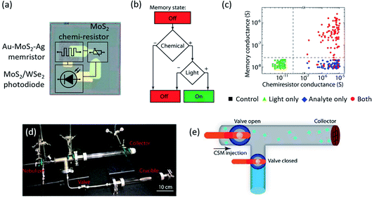 | ||
| Fig. 1 Monolithically fabricated colloidal state machine enabled by 2DMs. (a) 2DM-enabled aerosolizable sensors with on-board power, memory, and sensing element integrated.19 Dimension, 100 by 100 μm. (b) Block diagram showing logic of the CSM in (a). The memristor is switched on if and only if the analyte concentration and the light intensity are both higher than a threshold, as also evidenced by the experimental data in (c). (d) Image of the experimental set-up with a crucible filled with chemical analyte. Once the lower valve is open, saturated ammonia vapour (∼10 kPa) expands into the rest of the system. (e) Schematics of the pipe segment system (22 mm inner diameter), which has two separate valves for metering aerosolized CSMs (teal squares) or analyte. To allow for retrieval, a layer of cheesecloth served as a collector at the pipe endpoint. | ||
As a step towards furthering this goal, we have developed a suite of techniques and analysis around what we call colloidal state machines (CSMs) to differentiate these micrometer-scale entities from what are currently called “microrobots”. The latter term typically refers to centimeter or millimeter-scale ‘miniaturized’ robots,3 but micrometer-sized, non-sediment colloids require different properties. There has been sustained research interest in responsive micro- and nano-objects such as micro-swimmers and actuators4,5 that clearly benefit, can integrate into, and further the goal of the CSM. The ultimate vision is to generate CSMs as (electronically) integrated entities with onboard memory, sensing, energy harvesting, actuation, and communication, able to carry out tasks remotely and autonomously.
It is not immediately obvious that the miniaturization of robotics into the colloidal regime requires completely new fabrication methods, actuation mechanisms, energy sources and device architecture. Roboticists have been successful in reducing the size and weight of macroscopic robots. The record for miniature aerial robots was recently pushed down to 3.5 cm and 259 mg.3 Such systems can still obey similar fundamental design principles as their larger counterparts such as the meter-long robotic cheetah.6 Alternatively, CSMs as autonomous machines require components more than a billion times smaller, with the entire device volume under a picoliter and still integrated with the functionalities mentioned above. Therefore, the effort is not the equivalent of making a smaller-sized version of macroscopic counterparts. Physical laws and mechanisms differ at these reduced length scales. For example, in the micrometer world, surface forces start to dominate over those that are inertial or volumetric.7 CSMs have to be designed to consider local hydrodynamics, and can perhaps leverage them by suspension for prolonged periods without sedimentation. Similarly, a macroscopic robotic arm can be driven by electric motors and hydraulics. These actuation mechanism do not efficiently scale to the micron-scale environment. Indeed, microscopic actuators that have been successfully demonstrated are based on different mechanisms such as variance in thermal expansion coefficients.8,9 At the micron scale, it is well known that mechanical propellers need to be substituted with time-asymmetric mechanisms like bubbling and phoretic motion by virtue of the Scallop theorem.10 We can deduce from these examples that the success of a microscale CSM design, therefore, relies much more on intrinsic materials science: thermal, mechanical, and electronic properties, responsiveness to stimuli, compatibility of hetero-integration, as well as electrical energy utilization efficiency, chemical stability and mechanical robustness. In this regard, 2D materials show particular advantages for these tasks.
The expanding family of novel two-dimensional materials (2DMs) has provided an ever-growing arsenal of modules suitable for colloidal robotics. Armed with distinct, and often superior mechanical, chemical, or electrical properties in contrast to their respective bulk counterparts,11 the wide array of 2DMs have been used to build advanced (bio)sensors, actuators, (opto)electronic devices, logic circuits, memory elements, and power sources.12–16 For example, Miskin et al.’s graphene–silica bimorph actuators respond to pH variations in fractions of a second, paving the way towards “complex cell-sized machines”.17 Bessonov and colleagues, on the other hand, developed MoS2-based memory elements programmable by less than 0.2 V, suitable for the extremely energy-hungry microscale world.18
In our own recent work, we introduced and demonstrated several new CSM prototypes. In Koman et al. we demonstrate the first autonomous CSM: a 2D-electronics-grafted microparticle that can be aerosolized as an airborne sensor19,20 (Fig. 1a). Powered by a MoS2/WSe2 photodiode and connected in series with an analyte-sensing MoS2 chemiresistor, the inbuilt Au–MoS2–Ag memristor is switched on only when both light and analyte are present, analogous to an AND logic gate (Fig. 1b and c). A hexagonal boron nitride (hBN) monolayer meanwhile insulates the sensitive memory element from the environment. Of note, fabricating all the electrical components with 2DMs allowed the devices to survive aerosolization and bypass power limitations.20 The 2DMs enabled electronic particles, or aerosolizable electronics, to integrate energy harvesting, sensing, and memory into one, presenting a proto-example of a CSM (Fig. 1d and e). While the work demonstrates CSMs as autonomous chemical sensors, it also points to promising possibilities of biomedical applications as well. For instance, substituting the chemiresistor with Mannoor et al.’s bioselective graphene nanosensors could enable the capture and detection of single bacterial pathogens, as the binding of which triggers a similar resistance change.21
As an alternative to the top-down approach of Koman et al., we also introduced a bottom-up technique based on “autoperforation”22 for producing colloidal microparticles with two independently addressable, external 2D Janus faces via engineered crack propagation (Fig. 2a). This method, which we employ and build on in this work, turns crack propagation at the nanometer scale from a nuisance into a useful device fabrication tool in 2DM engineering. The method is distinct from Shim et al., who adopt controlled cracking for high-throughput production of wafer-scale 2DM monolayers.23 Autoperforation instead uses cracks to scissor or carve out micrometer-sized particles that are templated by a designed strain field (Fig. 2b and c). We showed that by encapsulating an inkjet-printed array between two layers of 2DM sheets (e.g. graphene, MoS2 and hBN), the engineered strain field guides the propagating cracks around the ink pillars, leaving behind individual particles enveloped by 2DMs (Fig. 2d). Using two monolayer graphene sheets as the top and back electrodes sandwiching memristive 2DM fillers, we demonstrated unconventional microscopic particles (under 10 picolitre volume) with onboard electrical memory arrays approaching the size of a biological cell (Fig. 2e). Specifically, the memory states within each particle can be switched by applying a voltage across the memristive phosphorene, MoS2, or graphene oxide ink filler, turning each autoperforated CSM into an intraparticle array of parallel, two-terminal electronic memory storage devices (Fig. 2f and g). As a result, chosen regions of a given electronic cell can be selectively switched, recorded, and erased, mapping out the letters “M”, “I”, and “T” in a digital format (Fig. 2e). Furthermore, the unique capability of the autoperforation technique to engineer both the CSM’s surface chemical environment and its interior filler composition opens these two-terminal electronic devices up for additional opportunities. For example, non-covalent functionalization of the particle exterior surface with capture sites to ligate with specific metallic residues and ionic species in water bodies and soil matrices, respectively (Fig. 2h), equips these electronic colloids with chemiresistive (Fig. 2i) and optical (Fig. 2j) sensory units that integrate readily into the existing functional modalities.
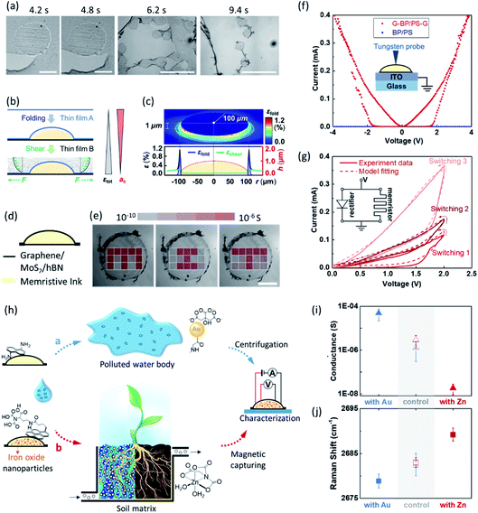 | ||
Fig. 2 Autoperforated colloidal state machines enabled by 2DMs. Adapted from ref. 22. (a) Optical micrographs of the bottom-up autoperforation technique showing the crack propagation in progress.22 The round shapes correspond to inkjet-printed discs which impose strain. Scale bars represent 100, 100, 1000, and 1000 μm. (b) Schematic illustration of the two-step process generating the strain field used in (a). The first step involves folding the graphene-containing thin film (A) on top of the curved polymer disk printed onto film (B), which has the same composition as (A). The second shearing step is facilitated by flowing an agitated liquid over the film-encapsulated disk, creating tensile stress within both films synergistic to the folding strain, modelled here as an outward-facing force F, pulling uniformly away from the film centre. The total strain (εtot) within the films increases as a result of this two-step process. The Griffith length (ac), on the other hand, decreases. (c) Local strain field after stacking/folding a thin polymer film (200 nm) onto a microdisk (radius![[thin space (1/6-em)]](https://www.rsc.org/images/entities/char_2009.gif) : :![[thin space (1/6-em)]](https://www.rsc.org/images/entities/char_2009.gif) height height![[thin space (1/6-em)]](https://www.rsc.org/images/entities/char_2009.gif) = =![[thin space (1/6-em)]](https://www.rsc.org/images/entities/char_2009.gif) 100 100![[thin space (1/6-em)]](https://www.rsc.org/images/entities/char_2009.gif) : :![[thin space (1/6-em)]](https://www.rsc.org/images/entities/char_2009.gif) 1) based on finite-element analysis. (d) Schematic of the sandwich CSM carved out by the crack “scissors”, equivalent to an intraparticle vertical memristor array in parallel. The conductivity map in (e) shows that each of these memristors can be switched on independently, thus mapping out letters “M”, “I”, and “T”. Scale bar, 100 μm. (f) Cross-plane I–V curves of microparticles G–BP (0.9 wt%)/PS–G, G–PS–G, and BP/PS. (g) I–V curves of three successive sweeps of 0 → 2 → 0 V (switching 1), 0 → 4 → 0 V (2), and 0 → 6→ 0 V (3) and the fitting curves based on the inset equivalent circuit. (h) Schematic illustration of the application of surface-functionalized G–PS/G microparticles or their magnetic counterparts as probes to electronically sense and record chemical species such as metal nanoparticles and ions in a water and b soil matrices, these microparticles can be collected via centrifugation or magnetic capture for electronic read out. (i and j), Surface in-plane electrical conductance (i) and graphene Raman 2D peak position (j) of the microparticles retrieved in (h). 1) based on finite-element analysis. (d) Schematic of the sandwich CSM carved out by the crack “scissors”, equivalent to an intraparticle vertical memristor array in parallel. The conductivity map in (e) shows that each of these memristors can be switched on independently, thus mapping out letters “M”, “I”, and “T”. Scale bar, 100 μm. (f) Cross-plane I–V curves of microparticles G–BP (0.9 wt%)/PS–G, G–PS–G, and BP/PS. (g) I–V curves of three successive sweeps of 0 → 2 → 0 V (switching 1), 0 → 4 → 0 V (2), and 0 → 6→ 0 V (3) and the fitting curves based on the inset equivalent circuit. (h) Schematic illustration of the application of surface-functionalized G–PS/G microparticles or their magnetic counterparts as probes to electronically sense and record chemical species such as metal nanoparticles and ions in a water and b soil matrices, these microparticles can be collected via centrifugation or magnetic capture for electronic read out. (i and j), Surface in-plane electrical conductance (i) and graphene Raman 2D peak position (j) of the microparticles retrieved in (h). | ||
It is encouraging to note how the nascent field of CSMs has been steadily expanding.24–26 Despite this, several technological challenges persist. One challenge specifically addressed in this work is locomotion. Unlike the features of onboard memory, sensing, and energy harvesting integrated onto colloid-sized machines, locomotion is an extremely energy intensive function. CSMs published so far travel passively with the surrounding fluids – a feature of the scale of this design. But for many tasks, propulsion will be specifically required. We outline such tasks and potential solutions in the latter parts of this work. As a technological solution to the propulsion problem that builds onto autoperforated CSMs, we leverage advances in the field of micro-propulsion and microswimmers to generate CSMs capable of locomotion. We introduce an inversion moulding technique compatible with 2DM autoperforation that allows for the patterning of an external catalytic surface to enable CSM translocation in an accompanying fuel bath. The velocity of the resulting propulsion is evaluated as a function of fuel concentration. We also summarize efforts to define and create a testbed for CSMs designed for complex navigation, such as in the case of the human circulatory system. We introduce conceptual CSM designs capable of solving such complex tasks and further the ultimate goals of this nascent field.
Results and discussion
The first goal of this work is to realize self-driven locomotion of autoperforated CSMs in energized environments, such as in a H2O2 bath. The approach is to functionalize the CSM with a geometrically defined platinum (Pt) patch as the catalytic element. In this section, we report the development of a fabrication method compatible with autoperforation22 to equip such Pt modules to graphene–CSM surfaces. This clean-room-free method involves a patterned Pt electrodeposition step on chemical vapour deposited (CVD) graphene, followed by an alignment process for the subsequent Pt–graphene–CSM autoperforation.Patterned Pt electrodeposition on graphene surfaces defined by inkjet printing
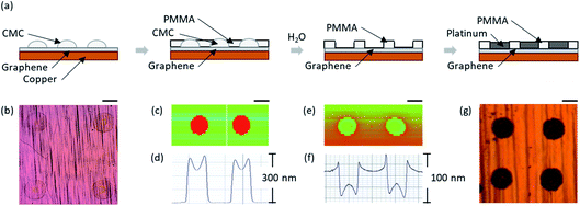
The implementation of this Pt-coated autoperforated CSM variant relies on a scalable and reliable method for Pt-deposition in controlled geometric shapes on the graphene “skin” for CSM encapsulation. We developed an inversion-moulding technique that allows us to create size-defined well-shaped patterns via inkjet printing in a high-throughput manner on top of CVD–graphene for Pt electrodeposition, as shown in Fig. 3a. The overall procedure is briefly described as follows. First, an array of carboxymethyl cellulose (CMC) disks were printed onto a monolayer of graphene grown via CVD on a copper (Cu) substrate (Fig. 3b). Second, a thin layer of polymethyl methacrylate (PMMA) was spin-coated atop the CMC array on the graphene/Cu substrate (Fig. 3c and d). The water-soluble CMC was then etched, thus exposing an array of graphene in the form of cylindrical PMMA wells (Fig. 3e and f). Pt was subsequently deposited onto the conductive graphene through electroplating using a platinum(IV) chloride (PtCl4) solution (Fig. 3g). This entire process is clean-room-free and perfectly compatible with the standard autoperforation method22 for CSM production en masse. The conditions for printing, spin-coating, and electroplating were optimized to improve the quality of Pt electrodeposition inside these inversion-moulded micro-wells.To better improve the consistency and uniformity of the electrodeposition, extensive parametric studies were conducted. The well depth and electroplating conditions were optimized in order to produce a solid, uniform array of Pt patches. The parameters of interest are the height of printed CMC (controlled by how many layers of CMC are printed), height of PMMA (tuned by the PMMA concentration and spin-rate), duration of electroplating, and concentration of the electrolyte solution.
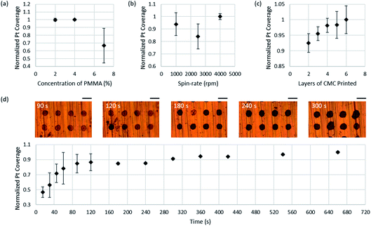
Three sets of samples were prepared using these conditions and were electroplated in 3 mM, 30 mM and 16.5 mM PtCl4 for 50 min. The 16.5 mM solution was chosen as the benchmark condition for the remainder of the study. Five copper–graphene samples were prepared with five arrays on each chip, with 6 layers, 5 layers, 4 layers, 3 layers, and 2 layers of CMC. Each set of copper–graphene chips was then spin-coated for 1 min under one of the five conditions: 2% PMMA at 1000 rpm, 2% PMMA at 2500 rpm, 2% PMMA at 4000 rpm, 4% PMMA at 4000 rpm, and 7% PMMA at 4000 rpm. The sample was then etched in water as already described. Profilometer measurements were taken of each sample. They were subsequently electroplated with a Pt counter electrode for various times. An optical microscope was used to image each array after every time interval. Five Pt patches were selected from each image and cropped. The integrated intensity was then obtained for each cropped image. The average inverted integrated intensity, or intuitively the “darkness”, was used as a quantitative metric for the electroplating quality.
Fig. 4 shows the quantified Pt electrodeposition quality for the various conditions tested. Both the spin-rate and concentration of PMMA affect the thickness of the PMMA coating. Fig. 4a suggests that when spin-rate is held constant at 4000 rpm, 2% and 4% yield similar results, both of which are significantly darker than that of 7%. We hypothesize that the 7% PMMA coating was too thick preventing contact between water and CMC, thus hindering sufficient etching of the CMC. Fig. 4b suggests that when concentration is held constant at 2%, 4000 rpm resulted in the densest Pt patches. Higher spin-rates should correspond to a thinner layer of PMMA which would presumably create a shallower well with less volume for deposition.
Fig. 4c shows that the coverage of Pt increases with increasing layers of sacrificial CMC. Increasing the layers of CMC should increase the depth of the well, thus creating more volume for Pt deposition. However, with more layers of CMC, the cross-sectional area of the Pt patch increased, a phenomenon we describe as “spilling-over.” Finding the optimal number of layers requires balancing these two opposing factors. Fig. 4d displays a time series of Pt coverage on graphene. The darkness of Pt increases nonlinearly over time and plateaus after around 540 s. From visual inspection, the Pt appeared to first deposit in a ring around the edge of the well base, the depositing within the well until the patch was fully covered, before “spilling-over” occurred.
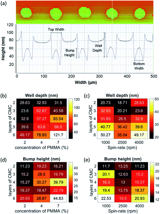
More insight into factors impacting the inversion-mould patterning was revealed from profilometer measurements of the PMMA wells after CMC etching (Fig. 5). The linear profiles revealed that a bump had formed within each well, creating a barrier and decreasing the volume available for Pt deposition. It seems unlikely that the bump was due to the CMC that remained after the etching process given the high solubility of CMC in water and the long duration of etching. We hypothesize that the bump was instead caused by shifting PMMA that migrated into the space evacuated by the CMC. The average well depth and bump height for each condition are shown in Fig. 5b–e. Fig. 5b and d reveal that both the well depth and bump height increase with the concentration of PMMA spun. Fig. 5d shows that the bump height for most layers was higher for 7% PMMA, consistent with the lower Pt coverage for 7% as shown in Fig. 4a. Fig. 5c and e suggest that 1000 rpm provides the largest well depth and bump height; however the trend did not monotonically decrease with spin-rate. The unexpected result for 2500 rpm was observed in both the profilometer measurements and the Pt integrated intensity. This may be the result of an anomaly in the fabrication of the 2500 rpm sample. Fig. 5b–e all suggest that well depth and bump height increase with more layers of CMC. Following the spilling-over observation, the width at the top of each well was extracted from each profilometer measurement. As anticipated, the well width increased with layers of CMC which is partially due to the nature of vertically stacking layers of an ink, and partially due to misalignment across layers. Because of the higher incidence of misalignment with 4–6 layers of CMC, it was determined that 3 layers of CMC was optimal for maximizing Pt deposition and minimizing spilling over.
Pt-coated Janus graphene CSMs via aligned inkjet printing and autoperforation
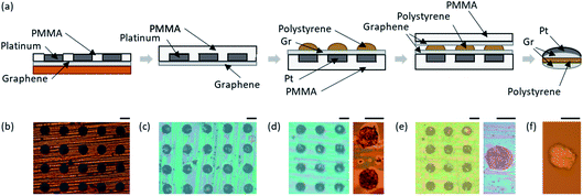
With the Pt electrodeposition on graphene process optimized, we then developed an alignment method that eventually allowed us to graft this Pt array/graphene stack onto microparticles using a variant of the previous autoperforation method22 for large-scale production of Pt/graphene–CSMs. In this process (Fig. 6), a second array of polystyrene/ethylene glycol ink (PS/EG) was aligned, printed onto the Pt array, and capped with a second layer of graphene before lifting-off of the entire stack. Specifically, PMMA was first spun onto the sample, which was then etched for Cu removal (Fig. 6c). The PS/EG ink was then printed onto the PMMA–Pt–graphene vertical stack by a commercial inkjet printer, aligned with the prefabricated array of Pt patches (Fig. 6d). A second layer of PMMA-supported graphene is subsequently transferred on top of the sample via the same wet transfer process, resulting in a PMMA–graphene–PS/EG–graphene–Pt–PMMA vertical stack (Fig. 6e). Finally, the entire array of Pt-coated autoperforated cells could be lifted-off simultaneously, allowing for mass production of CSMs (Fig. 6f). It turned out that the Pt-decorated graphene described in the previous section is perfectly compatible with the autoperforation technology. It should be noted that we anticipate the process to be facilely adaptable for 2DMs beyond graphene as well, as shown in prior literature for MoS2 and hBN.22 As patterning of the PMMA mask works for all 2D substrates, chemical or evaporative deposition methods may substitute electroplating for less conductive materials.Self-driven locomotion of Pt-coated Janus graphene–CSMs in H2O2
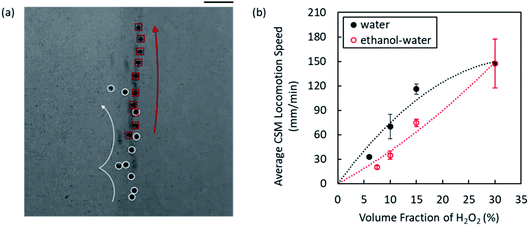
These Pt-coated graphene–CSMs (Fig. 6f) translocate inside a H2O2 bath via the generation of O2 bubbles (Fig. 7a). We observed a strong H2O2 concentration dependence for the locomotion speed of the Pt/graphene–CSMs. In one set of experiments, we recorded the particle trajectory of two or more particles and plotted their average distances with respect to their centre of mass as a function of time in an aqueous solution (Fig. 7b, black) and ethanol/water mixture (Fig. 7b, red), and calculated their average speed of translocation, respectively. In both cases, increased H2O2 concentration increases their speed of translocation (Fig. 7b). Notably, the CSMs appear to translocate more slowly in ethanol/water diluted H2O2 solution, which has a significantly reduced surface tension (as compared to the aqueous H2O2 solution), consistently across all H2O2 concentrations tested (Fig. 7b). Assuming a constant H2O2 decomposition (O2 generation) rate at similar H2O2 concentrations, we attribute the reduced CSM motility to the reduced critical radii for O2 bubble burst in ethanol/water mixtures as a result of the reduced surface tension.Looking forward – towards navigation in a complex fluidic network
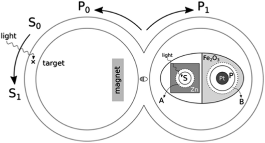
This biomedical task, perhaps exaggerated in Fantastic Voyage, has been critically deconstructed recently by Pervan and Murphey.27 Using a classical physiological model of the human circulatory system,28 they abstracted it as a complex fluidic network (Fig. 8a and b). The central machine task of the CSM is embodied in a simple test cell in the form of interconnected double circular paths (Fig. 8c). Particles circulate and initially select paths 0 or 1 randomly. A particle or CSM must be able to discover or otherwise identify a signal (marked by ×), permanently select this correct path, and recruit all others to select this path to the exclusion of the other in a form of reinforcement learning, akin to the immune response of leukocytes. This test cell and the task it embodies can be used to gauge the efficacy of algorithms and functions of the candidate CSMs. Aspects such as error correction, response time, and failure rates can be quantitatively assessed with such a test cell. Pervan and Murphey argue that particles capable of accomplishing this double circular closed path task have the basic architecture in the form of computation and actuation, to navigate a more complex network with an eye towards the human circulatory system.27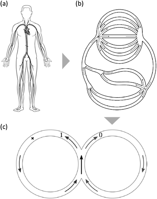 | ||
| Fig. 8 CSM conceptual design for a collective immune-like response. (a) The human circulatory system is a complex environment for CSMs to navigate, comprising branches and bifurcations as seen in (b) the corresponding abstracted drawing. However, recent theoretical analyses27 have proven that the success of an immune response in the complex landscape can be extrapolated from the CSM’s performance in (c) a simplified double circular track. The CSM should recruit its peers when a signal (the × mark) is detected. | ||
The locomotion ability compatible with autoperforation that we report in the previous section opens up possibilities for integrated smart CSMs which autonomously and actively explore their immediate environment. Wired with on-board CSM electronics previously reported,24,25 the self-driven colloidal robots may soon find use in probing confined and remote spaces guided by user-defined rules.29 This motivates the conceptual design of new CSMs that integrate locomotion, sensing, memory and communication in responses that mimic elements of the human immune system.
Demonstrating a collective immune response using CSMs: design 1
It is possible to design CSMs capable of complex, ensemble behaviours since their fabrication is scalable to large populations. With each CSM equipped with a Pt module, their collective locomotion upon interaction will allow for the investigation of how ensemble-level motility scales with system size, say, as the number of CSMs is increased from 3 to more than 1000. We are specifically interested in emergent properties that are only observable in large populations.30,31 In addition, we can look for emergent swarm behaviours of these smart particles under fundamentally different conditions from those covered by their macroscopic counterparts.33,33 As an example, while random behaviours might be a challenge in and of themselves for macroscopic systems, stochastic dynamics is readily available, and essentially “programmed in”, for these microscopic CSMs immersed in a thermal bath. There are aspects of collective behaviour that can only be observed via a system in such a context with a layer of stochastic noise constantly pumping energy and perturbation into the ensemble.Before diving directly into the CSM design that navigates the aforementioned complex fluidic channels, we first start with a simpler system targeting the peer recruitment sub-task – a feature of the human immune system. The fabrication approach of autoperforation allows one to create symmetry broken particles easily, and this can be leveraged for task-driven collective motion. Particles can be programmed to locate a chemical signal and move towards it, to then signal similar particles in a recruiting effort. The result is that a single trace signal can result in an amplified response and the amassing of resources to a specific location. This requires CSMs capable of complex chemotactic behaviour, inter-particle communication, memory and control. Building upon the existing Pt/graphene–CSM system fabricated in the previous section, chemo-responsive hydrogels can be added. As schematically shown in Fig. 9, we may program the hydrogel 1 (H1) over the Pt-free side to release a substance I (inhibitor), in the presence of a source signal. Next, the released I in the surrounding environment in turn triggers the contraction of hydrogel 2 (H2) over the Pt patches, thereby cutting off their access to the fuel, H2O2.
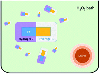 | ||
| Fig. 9 Schematic representation of the Pt/hydrogel–CSM design 1 inside a H2O2 bath with a Gaussian source signal. | ||
On a macroscopic level, the increased propensity for the CSMs to halt (measured by the decreased particle diffusivity) as they approach the point source should in principle formulate a strategy for the particles to “locate” the source position. With this specific example, we anticipate a collective behaviour for a large ensemble of chemically communicating, chemotactic CSMs that detect a signal and recruit others like a cascade. This behaviour will manifest analogous to the engulfing behaviour of biological immune cells, or the foraging behaviour of a group of ants (Fig. 9).34
The chemical reactions that occur in this control system can be described by the following chemical kinetics:
 | (1) |
 | (2) |
 | (3) |
 | (4) |
In the scenario that we have (i) an infinite reservoir of H2O2, and (ii) a point source S with a finite depletion mechanism in H2O2 such that the S concentration profile [S] is not a function of time, the following governing equations serve to describe the probability distribution of the particle (Pp):
 | (5) |
 | (6) |
The coupled system of partial differential equations then solves the probability of finding the particle as a function of the position vector and time, which highlights the need for a kinetic Monte-Carlo simulation of the particle trajectory.
A CSM solution to the double circular cell: design 2
Design 1 uses coupled locomotion and analyte sensing to achieve an analogous immune response. This can be used in a CSM design to address the task encoded by the double circular cell (Fig. 8c) as discussed earlier. This cell is meant to mimic the critical tasks involved in navigating the human circulatory system, for instance, as an ultimate biomedical application for CSMs. The actual system contains numerous bifurcations and branches which complicate targeted exploration (Fig. 8a and b). In this section, we show that design 2 (Fig. 10) enables an immune response in the context of the double circular cell (Fig. 8c) using only rudimentary forms of sensing and locomotion. That is, we envision a CSM to detect this target and inform its peers of the location.To enable this function, our conceptual design of a self-driven CSM system takes full advantage of the binary nature of bifurcations detailed in Pervan et al. (ref. 27). Shown in Fig. 10, the proposed learning algorithm requires two bits of memory on each CSM, a feature already reported previously:19,22 one to store the control policy (either P0 or P1, for left or right) and one to store whether the goal has been detected (either S0 or S1, for non-success or success). The mechanism is simple from the control theory point of view: once an agent encounters the target, S0 is switched to S1. When this PxS1 CSM encounters another pristine PyS0 agent, the latter’s policy bit Py is switched to Px only when Px ≠ Py. Table 1 shows that both agents will end up moving towards the signal as directed by the aligned P states.
| Case | Pristine CSM state (PyS0) | Signal CSM state (PxS1) | Final P states |
|---|---|---|---|
| I | P0 | P0 | Both P0 |
| II | P1 | P0 | Both P0 |
| III | P0 | P1 | Both P1 |
| IV | P1 | P1 | Both P1 |
A physical system requires more details. We propose that a CSM will be driven by both the global magnetic attraction and its own bubble propulsion (Fig. 10). While, by default, it enters the left loop in a flowing fluid due to the magnet (policy P0), it can also defy the field and take the right path when self-driven locomotion is activated (policy P1). For example, it can be a Pt-decorated autoperforated cell with switchable access to H2O2.
When this CSM encounters the target stimulus, say light, a chemical A is released. Experimentally, this can be realized by installing an irreversible light-sensitive pocket, the state of which determines the success bit (S in Fig. 10 inset):
| S0 + light → S1 + A | (7) |
The policy bit (P in Fig. 10 inset) will be another hydrogel patch (with chemical B embedded) over the Pt metal. When this patch is in its ‘open’ state, the Pt interacts with the H2O2, and at the same time, chemical B is released. This constitutes our two-bit system: the presence of chemical A indicates that a CSM has found the target (S1), and the absence of A indicates the opposite (S0). The presence of chemical B indicates the Pt policy is being used (P1) and the absence of chemical B, indicates the magnetic policy (P0).
The next step is to realize the P bit switching when a pristine CSM (PyS0) meets one that has seen light (PxS1). Note that physically, P1 switching to P0 and P0 to P1 should be triggered by two distinct mechanisms, which we term X and Y. If X and Y are chemical signals, they should be released when the two P states differ, hence corresponding to cases II and III in Table 1:
| P0 + Y → P1 + B | (8) |
| P1 + X → P0 | (9) |
As chemicals A and B are present for both cases, the differentiation of X (for switching P1 to P0) and Y (for P0 to P1) relies on determining whether A and B are released from the same CSM or separately. For this reason, we imagine that each cell has access to a constant on-board power source (e.g. a Zn–air battery). This enables us to differentiate cases II and III using a carefully chosen A–B pair such that the following requirement is satisfied:
| A + B → X | (11) |
| A + B + e− → Y | (12) |
Note that X and Y must be two distinct products and cannot be inter-converted. The final Table 2 tabulates all possible encounter scenarios. We see that with the proposed physical system, a CSM that has seen that target will be able to recruit its peers by aligning their policy bits with that of itself. A similar system therefore should succeed in the induction of an immune-like response in a complicated maze as well, as proven previously theoretically.27
| Case | Pristine CSM state | Signal CSM state | Chemical signal | Final CSM states |
|---|---|---|---|---|
| I | P0S0 | P0S1 | A | P0S0 and P0S1 |
| (No signal) | (A) | (No reaction) | (No change) | |
| II | P1S0 | P0S1 | A + B → X | P0S0 and P0S1 |
| (B) | (A) | P1 + X → P0 | P1 switch off | |
| III | P0S0 | P1S1 | Y | P1S0 and P1S1 |
| (No signal) | (A + B + e− → Y) | P0 + Y → P1 + B | P0 switch on | |
| IV | P1S0 | P1S1 | B, Y | P1S0 and P1S1 |
| (B) | (A + B + e− → Y) | (No reaction) | (No change) |
Conclusion
In summary, we expanded upon the previously reported autoperforation techniques to introduce the locomotion functionality to colloidal robotics. The new process, which requires simply a conventional inkjet printer, allows Pt patches to be selectively patterned and electroplated onto 2DMs, followed by the standard autoperforation procedure. The resultant Pt-decorated CSMs thereby demonstrate self-driven locomotion in an energized environment. We have shown via extensive parametric studies that the Pt motor element, designed to be very compatible with the autoperforation platform, can be facilely tailored for a desired coverage and thickness. The impact of the surrounding environment on the locomotion is thoroughly explored as well. Lastly, we demonstrated the implication of the new functionality in enabling complex CSM tasks by outlining two designs for a collective immune-type response. Overall, this work establishes the first step towards self-driven CSM locomotion within the autoperforation framework, and expands the armoury of functionalities available to researchers of colloidal robotics.Experimental details
We grew monolayer graphene on Cu substrates with the following protocol. Hydrogen, methane, and argon canisters feed into a quartz mixing tube inside a CVD furnace. CVD growth of graphene is carried out by heating copper foil to 1000 °C with a constant 30 sccm flow of hydrogen. The temperature is held constant at 1000 °C for 20 min. Methane is injected into the mixing tube at a constant flowrate of 0.5 sccm for 15 min. The sample is then bathed in hydrogen for 5 min before the furnace is turned off and allowed to cool to room temperature. The sample is then bathed in argon and allowed to return to standard pressure.The as-prepared graphene/Cu substrate is used directly for the subsequent inversion-moulding step. A carboxymethyl cellulose ink was prepared by dissolving 285 mg sodium carboxymethyl cellulose (Sigma-Aldrich, average Mw ∼ 90![[thin space (1/6-em)]](https://www.rsc.org/images/entities/char_2009.gif) 000) in 100 mL deionized water. A commercial Fujifilm Dimatix Materials Printer DMP-2850 was used to print a 6 × 20 array of CMC disks of radius 20 μm with 100 μm spacing onto graphene. 2% PMMA (MicroChem) was spun onto the sample at a typical spin-rate of 4000 rpm for 1 min. The sample was then etched in water for approximately 18 h. 1 cm2 of the sample was electroplated in a 3 mM PtCl4 solution with a Pt counter electrode and a constant 0.1 A current. Graphene is conductive which allows for the Pt to deposit only on the array of exposed graphene wells.
000) in 100 mL deionized water. A commercial Fujifilm Dimatix Materials Printer DMP-2850 was used to print a 6 × 20 array of CMC disks of radius 20 μm with 100 μm spacing onto graphene. 2% PMMA (MicroChem) was spun onto the sample at a typical spin-rate of 4000 rpm for 1 min. The sample was then etched in water for approximately 18 h. 1 cm2 of the sample was electroplated in a 3 mM PtCl4 solution with a Pt counter electrode and a constant 0.1 A current. Graphene is conductive which allows for the Pt to deposit only on the array of exposed graphene wells.
For the subsequent autoperforation process, a layer of 7% PMMA was spin-coated onto the sample at a spin-rate of 500 rpm for 10 min then 4000 rpm for 2 min. The sample was floated on an APS-100 Cu etchant for approximately 2 h, or until the Cu was completely etched away. The sample was then flipped onto a SiO2 wafer resulting in a PMMA–Pt–graphene vertical stack. The sample was annealed for 10 min at 125 °C. A dyed PS–EG ink was prepared by mixing 2 mL polystyrene and 2 mL ethylene glycol (both from Sigma-Aldrich), and dissolving approximately 2 mg rhodamine B into this mixture. A DMP-285 printer was used to print a 6 × 20 array of PS–EG aligned to the prefabricated array of Pt patches. The printed sample was annealed for 10 min at 125 °C. A separate sample of graphene was transferred by spin-coating 4% PMMA onto the graphene–copper for 1 min at 4000 rpm. The sample was then placed in APS-100 for approximately 2 h or until the copper was completely etched away. The PMMA–Pt–graphene–PS–EG vertical stack was capped with this second layer of graphene–PMMA and annealed for 10 min at 125 °C. The complete vertical stack is PMMA–graphene–PS–EG–graphene–Pt–PMMA. The sample was lifted-off in 10 mL of 80% ethanol heated from room temperature using a hot plate set to 120 °C with magnetic stirring. After 10 min, the lifted-off cells were centrifuged and rinsed with 12–13 mL of deionized water three times.
Conflicts of interest
There are no conflicts to declare.Acknowledgements
This work is supported by the US Air Force Office of Scientific Research (AFOSR) Multi University Research Initiative (MURI) grant on Foldable and Adaptive Two-Dimensional Electronics (FATE, award no. FA9550-15-1-0514) as well as the 2019 US Army Research Office MURI grant on Formal Foundations of Algorithmic Matter and Emergent Computation. The authors acknowledge characterization support from the MIT Center for Materials Science and Engineering. A. T. L. acknowledges the MIT Presidential Fellow programme. L. N. L. was supported by the Caltech Summer Undergraduate Research Fellowship. A. P. acknowledges the NSF Graduate Research Fellowship Program.References
- M. Sitti, Nature, 2009, 458, 1121–1122 CrossRef CAS.
- K. Han, C. W. Shields and O. D. Velev, Adv. Funct. Mater., 2018, 28, 1705953 CrossRef.
- N. T. Jafferis, E. F. Helbling, M. Karpelson and R. J. Wood, Nature, 2019, 570, 491–495 CrossRef CAS.
- X. Yan, Q. Zhou, M. Vincent, Y. Deng, J. Yu, J. Xu, T. Xu, T. Tang, L. Bian, Y. X. J. Wang, K. Kostarelos and L. Zhang, Sci. Robot., 2017, 2, 1–15 Search PubMed.
- B. Yigit, Y. Alapan and M. Sitti, Adv. Sci., 2019, 6, 1801837 CrossRef.
- H.-W. Park, P. M. Wensing and S. Kim, Int. J. Rob. Res., 2017, 36, 167–192 CrossRef.
- M. Sitti, Mobile Microrobotics, MIT Press, Cambridge, MA, 2017 Search PubMed.
- S. E. Zhu, R. Shabani, J. Rho, Y. Kim, B. H. Hong, J. H. Ahn and H. J. Cho, Nano Lett., 2011, 11, 977–981 CrossRef CAS.
- M. Z. Miskin, K. J. Dorsey, B. Bircan, Y. Han, D. A. Muller, P. L. McEuen and I. Cohen, Proc. Natl. Acad. Sci. U. S. A., 2018, 115, 201712889 CrossRef.
- J. L. Moran, in Robotic Systems and Autonomous Platforms, Elsevier, 2019, pp. 129–177 Search PubMed.
- P. Liu, A. L. Cottrill, D. Kozawa, V. B. Koman, D. Parviz, A. T. Liu, J. F. Yang, T. Q. Tran, M. H. Wong, S. Wang and M. S. Strano, Nano Today, 2018, 21, 18–40 CrossRef CAS.
- Q. H. Wang, K. Kalantar-Zadeh, A. Kis, J. N. Coleman and M. S. Strano, Nat. Nanotechnol., 2012, 7, 699–712 CrossRef CAS.
- M. Chhowalla, H. S. Shin, G. Eda, L. J. Li, K. P. Loh and H. Zhang, Nat. Chem., 2013, 5, 263–275 CrossRef.
- M. Chhowalla, D. Jena and H. Zhang, Nat. Rev. Mater., 2016, 1(11), 16052 CrossRef CAS.
- H. Zhang, ACS Nano, 2015, 9, 9451–9469 CrossRef CAS.
- B. Mailly-Giacchetti, A. Hsu, H. Wang, V. Vinciguerra, F. Pappalardo, L. Occhipinti, E. Guidetti, S. Coffa, J. Kong and T. Palacios, J. Appl. Phys., 2013, 114(8), 084505 CrossRef.
- M. Miskin, K. Dorsey, B. Bircan, Y. Han, D. Muller, P. McEuen and I. Cohen, Proc. Natl. Acad. Sci. U. S. A., 2018, 115, 201712889 CrossRef.
- A. A. Bessonov, M. N. Kirikova, D. I. Petukhov, M. Allen, T. Ryhänen and M. J. A. Bailey, Nat. Mater., 2015, 14, 199–204 CrossRef CAS.
- V. B. Koman, P. Liu, D. Kozawa, A. T. Liu, A. L. Cottrill, Y. Son, J. A. Lebron and M. S. Strano, Nat. Nanotechnol., 2018, 13(9), 819–827 CrossRef CAS.
- I. Georgescu, Nat. Rev. Mater., 2018, 41578 Search PubMed.
- M. S. Mannoor, H. Tao, J. D. Clayton, A. Sengupta, D. L. Kaplan, R. R. Naik, N. Verma, F. G. Omenetto and M. C. McAlpine, Nat. Commun., 2012, 3(1), 763 CrossRef.
- P. Liu, A. T. Liu, D. Kozawa, J. Dong, J. F. Yang, V. B. Koman, M. Saccone, S. Wang, Y. Son, M. H. Wong and M. S. Strano, Nat. Mater., 2018, 17, 1005–1012 CrossRef CAS.
- J. Shim, S.-H. Bae, W. Kong, D. Lee, K. Qiao, D. Nezich, Y. J. Park, R. Zhao, S. Sundaram, X. Li, H. Yeon, C. Choi, H. Kum, R. Yue, G. Zhou, Y. Ou, K. Lee, J. Moodera, X. Zhao, J.-H. Ahn, C. Hinkle, A. Ougazzaden and J. Kim, Science, 2018, 8126, eaat8126 Search PubMed.
- S. Lee, A. Cortese, A. Gandhi, E. Agger, P. L. McEuen and A. C. Molnar, IEEE Trans. Biomed. Circuits Syst., 2018, 1 Search PubMed.
- M. Hempel, E. McVay, J. Kong and T. Palacios, Bull. Am. Phys. Soc., APS March Meeting 2018, http://meetings.aps.org/link/BAPS.2018.MAR.X37.4 Search PubMed.
- A. J. Cortese, C. L. Smart, T. Wang, M. F. Reynolds, S. L. Norris, Y. Ji, S. Lee, A. Mok, C. Wu, F. Xia, N. I. Ellis, A. C. Molnar, C. Xu and P. L. McEuen, Proc. Natl. Acad. Sci. U. S. A., 2020, 117(17), 9173–9179 CrossRef CAS.
- A. Pervan and T. D. Murphey, Bayesian Particles on Cyclic Graphs, IEEE Int. Conf. on Intelligent Robots and Systems (IROS), 2020, http://ras.papercept.net/images/temp/IROS/files/2078.pdf Search PubMed.
- H. H. Hardy, R. E. Collins and R. E. Calvert, Med. Biol. Eng. Comput., 1982, 20, 550–564 CrossRef CAS.
- J. F. Yang, P. Liu, V. B. Koman, A. T. Liu and M. S. Strano, in Robotic Systems and Autonomous Platforms, Elsevier, 1st edn, 2019, pp. 361–386 Search PubMed.
- G. S. Redner, M. F. Hagan and A. Baskaran, Phys. Rev. Lett., 2013, 110, 1–5 CrossRef.
- G. S. Redner, A. Baskaran and M. F. Hagan, Phys. Rev. E: Stat., Nonlinear, Soft Matter Phys., 2013, 88, 012305 CrossRef.
- M. Rubenstein, A. Cornejo and R. Nagpal, Science, 2014, 345, 795–799 CrossRef CAS.
- W. Savoie, T. A. Berrueta, Z. Jackson, A. Pervan, R. Warkentin, S. Li, T. D. Murphey, K. Wiesenfeld and D. I. Goldman, Sci. Robot., 2019, 4(34), eaax4316 CrossRef.
- R. Chadab and C. Rettenmeyer, Science, 1975, 188, 1124–1125 CrossRef CAS.
Footnotes |
| † Electronic supplementary information (ESI) available. See DOI: 10.1039/d0fd00030b |
| ‡ These authors contributed equally. |
| This journal is © The Royal Society of Chemistry 2021 |

