
 Open Access Article
 This Open Access Article is licensed under a
 Creative Commons Attribution 3.0 Unported Licence
In situ synchrotron pair distribution function analysis to monitor synthetic pathways under electromagnetic excitation†
Nathan
Nakamura
 a,
Laisuo
Su
a,
Jianming
Bai
b,
Sanjit
Ghose
b and
B.
Reeja-Jayan
*a
a,
Laisuo
Su
a,
Jianming
Bai
b,
Sanjit
Ghose
b and
B.
Reeja-Jayan
*a
aDepartment of Mechanical Engineering, Carnegie Mellon University, Pittsburgh, PA 15213, USA. E-mail: bjayan@andrew.cmu.edu
bBrookhaven National Laboratory, National Synchrotron Light Source II, Upton, NY 11973-5000, USA
First published on 19th May 2020
Abstract
Electromagnetic (EM) fields, specifically microwave radiation (MWR), can significantly influence the synthesis of ceramic oxide materials and promote rapid, low-temperature growth. However, the mechanisms by which EM fields affect the phase formation process are not well understood. A major limitation to increasing this understanding has been the lack of information regarding dynamic changes in local atomic structure during MWR exposure compared to conventional hydrothermal synthesis routes. Here, we utilize in situ synchrotron X-ray pair distribution function (PDF) analysis to monitor MWR-assisted SnO2 nanoparticle synthesis. A clear impact of the EM field is demonstrated, with MWR inducing changes in nearest neighbor distances and peaks in oxygen atomic displacement that do not occur during synthesis without MWR exposure. The observed local structural disorder serves as a precursor to rapid rutile SnO2 nanoparticle crystallization, suggesting that EM field-assisted growth is mediated by changes to the oxygen sublattice. These findings further our understanding of the mechanisms underlying MWR-assisted synthesis and represent a step towards utilizing EM fields to engineer tailored atomic structures for a broad range of applications.
1. Introduction
The application of electromagnetic (EM) fields during materials synthesis can promote effects not observed using conventional routes.1,2 One such example is the use of microwave radiation (MWR) at a frequency of 2.45 GHz to induce rapid, low-temperature crystallization in ceramic materials.3,4 Additionally, MWR has been shown to impact atomic structure and phase transitions in ways not observed without EM field exposure.5–10 These effects have made MWR-assisted synthesis an appealing option for a wide variety of material systems,2 with applications in Li-ion batteries,11,12 photovoltaics,13,14 and catalysis.15,16 However, the mechanisms underlying the role of EM fields in promoting phase formation and structural transitions remain unclear.1,2,17 This lack of mechanistic understanding has limited the widespread use of EM fields in materials design.Specifically, debate remains surrounding the role of potential EM field-driven effects on atomic structure that are not tied to thermal effects such as rapid or volumetric heating.2,17–20 A significant bottleneck in understanding these mechanisms has been the lack of detailed information regarding how EM fields can alter local atomic structure, especially during EM field exposure. Monitoring these dynamic changes in local atomic structure is critical to understanding the mechanisms underlying EM field-assisted synthesis, as they can provide insight into the structural changes influencing phase formation. A lack of instrumentation enabling in situ characterization of atomic structure during EM field exposure has contributed to this gap in knowledge.
Pair distribution function (PDF) analysis is an ideal tool for such in situ structural studies, as it can be used to quantitatively characterize both crystalline and amorphous atomic structures.21,22 PDF thus contrasts with the more commonly used X-ray diffraction (XRD) technique, which is applicable to well-ordered materials and is limited in characterizing systems with structural disorder or nanoscale features. Indeed, in situ PDF studies have been invaluable in determining phase formation pathways, particularly during hydrothermal nanoparticle synthesis.23–27 These insights are made possible by the ability to characterize changes in the local atomic structure which serve as precursors to phase transitions and crystalline phase formation. In general, in situ PDF characterization can provide real-time structural information and reveal mechanistic insights unavailable when performing ex situ studies or analyzing only crystalline atomic structures.
Despite the benefits of utilizing PDF analysis during in situ structural studies, it has scarcely been applied to MWR-assisted synthesis. This is due to the challenges associated with developing instrumentation enabling simultaneous X-ray and EM field exposure during hydrothermal synthesis. Monitoring local atomic structure via in situ PDF analysis during MWR exposure has been achieved in only two prior cases, both using the same microwave instrumentation at beamline BL08W at the Spring-8 synchrotron facility. This reactor was used to demonstrate that layered titanate precursor solutions can induce layered lepidocrocite titanate phase formation with no intermediate phases.28 Additionally, complex zeolite crystallization was shown to be promoted by the ordering and formation of large ring structures from an aluminosilicate precursor.29
These prior studies successfully revealed crystallization pathways during MWR-assisted synthesis. However, no comparison was made to synthesis without EM field exposure. Therefore, it is difficult to discern if the phase formation mechanisms align with conventional hydrothermal synthesis or investigate the potential existence of MWR-specific structural effects. Phase formation processes will also differ based on the material system, necessitating in situ PDF studies on other ceramic oxide materials. This comparison across synthesis conditions and material types is critical, as different chemical precursors and synthesis conditions have important implications for the resultant phase, size, and properties of nanoparticles during hydrothermal synthesis.30,31 Therefore, additional in situ PDF studies during MWR-assisted synthesis and direct comparisons to synthesis without EM field exposure are required. Such investigations can provide a more holistic viewpoint regarding EM field effects on phase formation and advance understanding of the mechanisms underlying MWR-assisted synthesis.
Here, we implement a custom-built microwave reactor enabling in situ PDF analysis of SnO2 nanoparticle growth. We further compare these results with in situ PDF studies of conventional hydrothermal synthesis. Such an experimental comparison clearly demonstrates how MWR impacts atomic structure during phase formation. SnO2 is chosen as a model system due to its applications in gas sensing,32–34 as an anode for Li-ion batteries,35,36 and as a catalytic material.37 We find that MWR-assisted synthesis promotes rapid rutile SnO2 nanoparticle growth relative to conventional hydrothermal synthesis. MWR-assisted crystalline phase formation is predated by large increases in oxygen displacement which do not occur without EM field exposure. These large displacements are not observed on the tin sublattice, suggesting that local structural distortions on the oxygen sublattice are a critical driving factor in EM field-assisted growth. Significant changes in the chemical precursor structure are also observed, indicating a change in the synthetic pathway during MWR-assisted synthesis. Understanding how MWR influences phase formation in SnO2 represents an important step forward in fully understanding the mechanisms underlying EM field-assisted synthesis.
2. Methods
2.1 Microwave reactor design and MWR-assisted synthesis
MWR-assisted synthesis was performed using a microwave waveguide custom-built for in situ X-ray experiments, designed in collaboration with Gerling Applied Engineering (Fig. 1). The waveguide consists of four components: (1) a sliding short, which allows the length of the waveguide to be adjusted to maximize electric field intensity at the sample position. (2) A waveguide section designed to hold the synthesis setup during MWR exposure. X-ray inlet/outlet is enabled by a straight inlet port 0.25 inch in diameter and an outlet port starting at 0.25 inches and tapering out at a 45° angle to accommodate the scattered X-rays. Additional features on the sides of the chamber enable synthesis tubing to be held in the chamber. (3) A 3-stub tuner, which assists with impedance matching between the sample-loaded waveguide and the applied field to maximize power absorption to the sample. (4) Lastly, components (1)–(3) are connected to an MKS SG1024 solid state microwave generator via a coaxial cable. The SG1024 can apply up to 1000 W power in a frequency range of 2.4 to 2.5 GHz. We use a frequency of 2.45 GHz for all experiments reported. The custom-built reactor provides the capability to adjust EM field parameters (e.g., frequency, electric field maxima) for specific material systems. The modular nature of this system has two key advantages over modifications to commercial microwave reactors: (1) compatibility with custom sample-holding apparatuses, and (2) applicability for other in situ characterization studies outside of X-ray scattering. This creates the opportunity to study EM field-assisted reactions across different materials utilizing a wide variety of characterization techniques.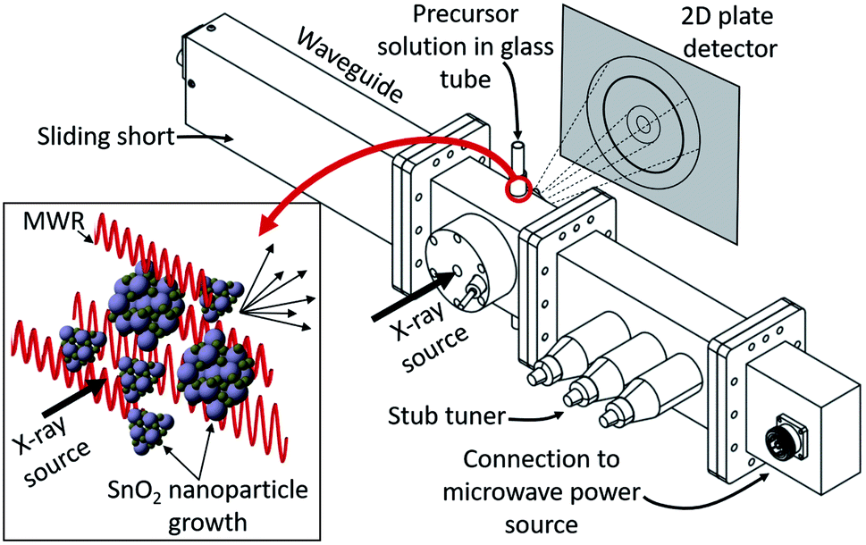 | ||
| Fig. 1 Custom-built waveguide enabling in situ X-ray scattering experiments during MWR-assisted synthesis. Precursor solutions are held in a borosilicate glass tube aligned with the X-ray inlet and outlet ports. The inset displays the process of X-ray scattering during MWR-assisted nanoparticle synthesis occurring inside the reaction tube. A sliding short and stub tuner enable adjustable waveguide length and optimal MWR absorption by the sample, respectively. The waveguide is supplied MWR at a frequency of 2.45 GHz via a coaxial cable connection to a solid state microwave power source. This reactor was designed in collaboration with Gerling Applied Engineering. | ||
Reactions were performed in 3 mm OD borosilicate tubes with 0.3 mm wall thickness (Hilgenberg GmbH, Germany). A 1 M aqueous solution of tin(IV) chloride pentahydrate (Sigma Aldrich, USA) was sealed inside the reaction tubes using graphite ferrules (Trajan Scientific, USA) and standard 3 mm Swagelok caps. This setup is based on similar experiments which have successfully demonstrated in situ PDF analysis during conventional hydrothermal synthesis, modified for compatibility with a microwave reaction system.38,39
In our experiments, SnO2 nanoparticles were synthesized from the aqueous precursor solution using both conventional and MWR-assisted synthesis. Conventional synthesis was performed by mounting a heat gun set to an output temperature of 200 °C to the outside of the microwave chamber (Fig. S1†). For MWR-assisted synthesis, 2 conditions were used: (1) MWR exposure only and (2) a mixed heating condition which applies both MWR and conventional heating. Synthesis with MWR exposure only was performed by pulsing 40 W of microwave power with an on/off time of 5 seconds. The pulsed MWR deposition was used to limit pressure buildup during the reaction. Pulsing MWR exposure also results in significantly slower heating rates compared to conventional experiments. To provide a more direct comparison to conventional synthesis, it is preferable to perform MWR-assisted synthesis with a similar heating rate as the conventional experiments. This is accomplished via a mixed MWR-conventional heating condition, which creates a heating profile similar to conventional experiments. Mixed heating utilizes the heat gun to better replicate the heating rate of conventional synthesis while simultaneously applying MWR to investigate EM field effects. This allows for a more direct comparison between MWR-assisted and conventional nanoparticle growth. Mixed heating conditions were implemented with an MWR power of 40 W and a 5 s on/off pulse period and heat gun temperatures of 150 °C. In both MWR-only and mixed heating experiments, MWR was introduced 1 minute after PDF acquisition began. Conventional heating was introduced immediately upon starting PDF data acquisition. A reaction time of 35 minutes was used for all conditions.
The solution temperature was measured by attaching a fiber optic temperature probe (Neoptix, Canada) to the outside of the reaction tube via a thermally conducting ceramic paste (Arctic Silver, USA). When conventional heating is applied, the side of the reaction tube facing the heat gun will be at a higher temperature than the opposite side of the tube. To account for this difference, temperature measurements were taken on both the heat gun and opposite side and averaged to obtain an estimate of the reaction temperature. MWR heats the solution volumetrically, and thus both sides will be at the same temperature during synthesis with only MWR exposure. The actual steady-state synthesis temperatures of the precursor solution were 150 °C for the conventional heating condition and 140 °C for mixed heating (Fig. S2A and B†). The MWR-only heating condition heats slowly over the course of the reaction time due to the pulsed MWR deposition and may not have completely reached steady-state by the end of the reaction. The temperature after the 35 minutes reaction time was 140 °C (Fig. S2C†). All future references to the synthesis temperature refer to this experimentally measured temperature, rather than the heat gun output temperature.
2.2 Pair distribution function (PDF) data collection and analysis
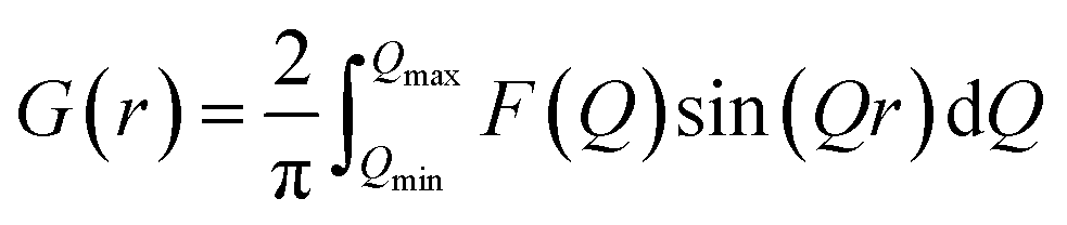
In situ PDF experiments were carried out at the National Synchrotron Light Source II (NSLS-II), Brookhaven National Laboratory. The microwave reactor was installed at beamline 28-ID-2. PDF data was collected on a 2D PerkinElmer silicon detector using the rapid acquisition PDF geometry with a sample-to-detector distance of 275.1 mm.40 Ni in a Kapton capillary was used to calibrate the sample-to-detector distance, and an X-ray wavelength of 0.1949 Å was used (Table S1†).2D total scattering images were converted to 1D intensities, I(Q), using Fit2D.41 A mask was applied to eliminate contributions to I(Q) from the heat gun, beamstop, and dead pixels (Fig. S3†). PDFgetX3 (ref. 42) was then used to obtain the total scattering structure function, F(Q), and generate the final PDF G(r). G(r) is defined by
3. Results and discussion
3.1 Conventional synthesis
The formation of crystalline rutile SnO2 nanoparticles from the aqueous precursor was successfully monitored during conventional hydrothermal synthesis (Fig. 2A). The first step in our PDF analysis is to effectively characterize the structure of the aqueous precursor solution. The precursor structure was approximated using a mer-[SnCl3(H2O)3]+ complex, which prior in situ PDF studies during high-pressure hydrothermal synthesis have identified as a suitable descriptor of the aqueous solution used.44 Refinements using the mer-[SnCl3(H2O)3]+ structure utilized a scale factor, Sn–O and Sn–Cl bond distances (dSn–O, dSn–Cl), and anisotropic atomic displacement parameters (ADPs). ADPs were restrained based on whether their vibrations are longitudinal (Ul) or transverse (Ut) to the bond direction. H atoms were omitted, as they have a negligible effect on the measured PDF due to their weak X-ray interaction. This approach suitably models the nearest neighbor Sn–Cl and Sn–O peaks but does not account for many structural features observed past 4 Å (Fig. 2B).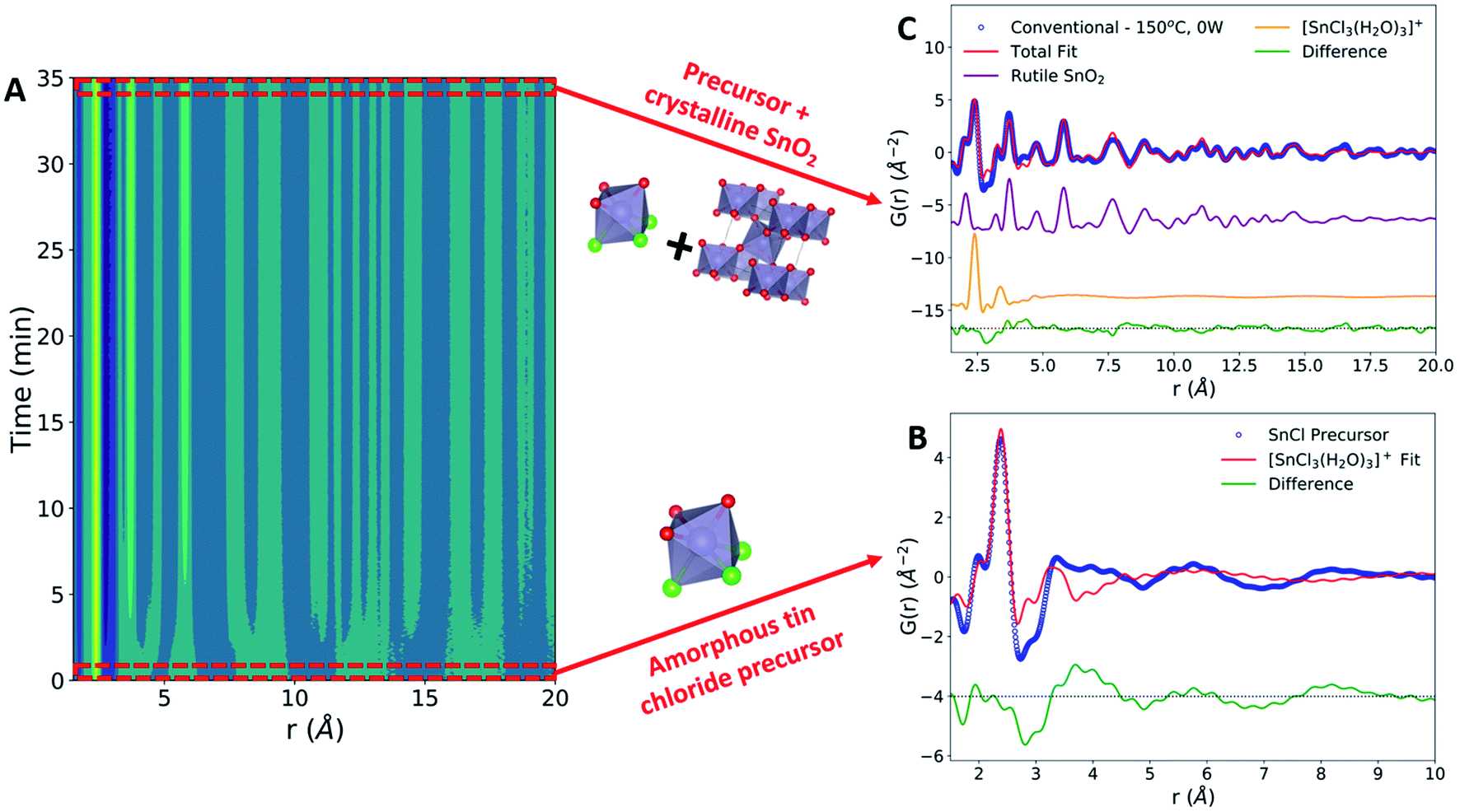 | ||
| Fig. 2 Conventional hydrothermal SnO2 nanoparticle synthesis. (A) Contour plot demonstrating the growth of crystalline PDF peaks over time. (B) Experimental PDF data from the tin chloride precursor solution (blue) with the refinement to the [SnCl3(H2O)3]+ complex (red). The difference between the experimental data and the fit is shown offset below in green. (C) PDF data of the final synthesis product (blue) refined to a two-phase model (red). The total two-phase fit is a mixture of the crystalline rutile phase (purple) and the [SnCl3(H2O)3]+ complex (orange). The difference from the total fit is shown offset below in green. | ||
The inability of our model to fit these higher-r features can be attributed to the lack of complexity in our starting model. Previous Nuclear Magnetic Resonance (NMR) spectroscopy studies have demonstrated that 1 M aqueous tin chloride solutions contain a mixture of [SnCl6−n(H2O)n]n−2 and [Sn(H2O)6−y(OH)y](4−y)+ complexes.45 While [SnCl3(H2O)3]+ is present in the highest percentage, it constitutes only approximately 40% of the complexes present and thus is unlikely to fully represent the experimental data. Additionally, we observe broad peaks in the PDF at r values larger than the size of any single precursor complex. These peaks may be caused by interparticle correlations,46,47 and are not modeled in the current framework. Additional low-intensity oscillations in the measured PDF may also be due to termination ripples caused by the finite Q-range of the experimental PDF measurements.22 Despite these shortcomings, the current model well represents the Sn–O and Sn–Cl bond distances, which are the most critical for observing the change in the precursor during synthesis. Therefore, fitting to only the [SnCl3(H2O)3]+ complex provides an adequate descriptor of the precursor structure and allows us to monitor structural changes during synthesis. The precursor structure observed prior to conventional synthesis is found to be consistent across all datasets collected (Fig. S4 and Table S3†).
The conventional synthesis experiment results in the formation of a crystalline rutile phase (Fig. 2C). The rutile phase was modeled by refining to lattice parameters (a, c), a scale factor, a low-r correlation parameter (δ1),48 spherical particle size,49 and isotropic atomic displacement parameters (Uiso) for Sn and O atoms. All refinements to the final synthesis product include both the crystalline rutile phase and the amorphous [SnCl3(H2O)3]+ complex. Observation of peak intensities before and after SnO2 crystallization reveals that the rutile Sn–Sn and Sn–O peaks form without a significant decrease in the Sn–Cl peak intensity (Fig. S5†). Post-synthesis, the Sn–Cl peak has been labelled as Sn–C/O due to the potential for overlap in Sn–Cl, Sn–O, and O–O interatomic distances in this r-range. The slight shift in the Sn–Cl/O peak observed can be attributed to this peak overlap or changes in the Sn–Cl bond distance.
The high intensity of the final Sn–Cl peak indicates that the rutile SnO2 formation mechanism during conventional heating is based in reorganization of Sn–O octahedral units present in the [Sn(H2O)6−y(OH)y](4−y)+ complexes, not in the breaking of Sn–Cl bonds present in the [SnCl6−n(H2O)n]n−2 complexes. Therefore, the [SnCl6−n(H2O)n]n−2 complexes are not active during conventional hydrothermal SnO2 phase formation. This finding aligns with prior results from conventional hydrothermal synthesis experiments utilizing an identical chemical precursor at concentrations of 2 and 4 M,44 validating the in situ data collection performed in our custom reactor. However, the previous work pressurized the reaction to 250 bar, while our synthesis system applies no external pressure and has an upper pressure limit of 15 bar set by the borosilicate reaction tubes. This demonstrates that the formation mechanism of rutile SnO2 from aqueous tin chloride solutions during conventional hydrothermal synthesis remains similar even under relatively mild conditions. This validation of the rutile SnO2 formation mechanism under conventional heating conditions allows for a direct comparison with the synthetic pathway during MWR-assisted synthesis.
3.2 MWR-only and mixed MWR-conventional synthesis
We observed that SnO2 nanoparticle synthesis was clearly influenced by the presence of MWR, resulting in enhanced growth relative to conventional hydrothermal synthesis. Two MWR-assisted synthesis conditions were used, with both resulting in improved nanoparticle growth: (1) MWR-only and (2) mixed MWR-conventional. The mixed heating condition was used to provide a heating rate similar to conventional experiments, allowing for a more direct comparison between the heating profiles. The MWR-only condition is unable to replicate this heating profile due to the pulsed nature of MWR deposition but demonstrates improved SnO2 growth despite the slower heating rate.In all experiments with MWR exposure, the final crystalline phase observed remains rutile (Fig. S6†). No significant differences in the rutile lattice parameters are observed between conventional and MWR-assisted synthesis (Fig. S7†). However, significant differences in the final Bragg peak intensity and broadening exist in the raw total scattering data (Fig. 3A). MWR-assisted experiments contain sharper, higher intensity Bragg peaks, indicating larger SnO2 nanoparticle sizes. This is confirmed via PDF analysis, where the final product for the MWR-assisted samples display higher intensity rutile peaks out to larger r-values, which is indicative of larger nanoparticle sizes (Fig. 3B).
 | ||
| Fig. 3 (A) Raw total scattering data, I(Q), for the conventional (green), mixed MWR-conventional (red) and MWR-only (blue) synthesis conditions. Sharper peaks are present in the final product for MWR-grown samples. (B) PDF data, G(r), for the same datasets as in (A). The increase in Bragg intensity shown in (A) is found to be due to an increase in particle size, as seen by the increase in intensity of peaks at higher r values for samples grown by MWR-assisted synthesis. | ||
PDF refinements over the entire reaction time confirm the MWR-enhanced nanoparticle synthesis, with faster growth and larger particles observed under MWR exposure (Fig. 4). The final nanoparticle size for MWR-only and mixed heating conditions were 25.1 and 32.4 Å, respectively. Conventional heating results in a particle size of 23.5 Å (Table S4†). The rutile phase was included in refinements at the time which rutile peaks became clearly visible, leading to a predicted particle size of 0 Å before this time. Particle size information is available at earlier times under conditions with conventional heating due to the nature of the experimental setup. Conventional heat is introduced to the system immediately upon starting PDF data acquisition, while MWR is applied approximately 1 minute after data acquisition has begun. This leads to a longer delay time at room temperature in the MWR-only condition, and thus a slightly delayed start to phase formation. Due to the slower heating rate associated with the MWR-only condition, more time is spent at lower synthesis temperatures. This explains the smaller particle size of the MWR-only condition relative to the mixed heating condition, which reaches its steady-state temperature quickly and thus applies MWR while maintaining a higher synthesis temperature. However, both MWR-assisted conditions outperform the conventional synthesis experiment.
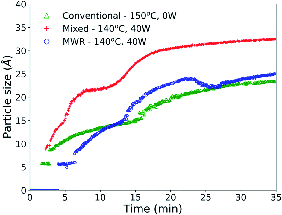 | ||
| Fig. 4 Spherical particle diameter for SnO2 nanoparticles synthesized conventionally without MWR exposure (green), with mixed MWR-conventional heating (red), and with only MWR exposure (blue). The presence of MWR promotes larger nanoparticles and more rapid growth relative to conventional synthesis at similar temperatures, indicating an effect of MWR on growth. The delay in nanoparticle growth for the MWR-only samples is due to a delay in the beginning of MWR exposure during synthesis, as explained in methods. | ||
Enhanced SnO2 nanoparticle growth occurs despite MWR-assisted synthesis occurring at similar temperatures than the conventional heating experiment. This behavior contrasts conventional nanoparticle growth, where higher synthesis temperatures regularly correspond to larger particles.27,44,50,51
3.3 Phase formation mechanisms
The enhanced nanoparticle growth observed during MWR occurs at similar temperatures to conventional synthesis, indicating that the presence of MWR is driving SnO2 synthesis. This invites discussion into the mechanisms underlying rutile SnO2 phase formation under MWR exposure. To study the origin of the observed change in kinetics, the ADPs and local atomic structure were studied via PDF analysis. The ADP, Uiso, is obtained from PDF refinements and represents the average displacement of atoms from their expected lattice position.22Uiso encompasses both thermal vibrations and static displacements. Thus, Uiso will be higher in systems at higher temperatures or with more structural disorder. Sn Uiso values converge to similar values regardless of synthesis conditions (Fig. 5A). The high values at short synthesis times and subsequent decay can be attributed to the crystallization process. Rutile will not be fully crystallized or particle sizes will be extremely small at early reaction times, leading to a distorted structure and broader PDF peaks that are accommodated in the refinement process by high Uiso values. As nanoparticles grow and rutile crystallizes, the Sn displacement parameters converge to reasonable values.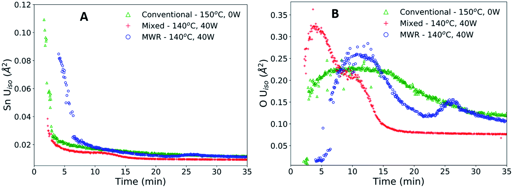 | ||
| Fig. 5 (A) Sn atomic displacement parameters (Uiso) for conventional (green), mixed (red), and MWR-only (blue) synthesis conditions. (B) O Uiso values for the same reaction conditions shown in (A). the presence of multiple peaks in O Uiso during MWR-assisted reactions indicates changes on the oxygen sublattice not present during conventional hydrothermal conditions. | ||
The O Uiso values, however, are significantly impacted by MWR. The presence of MWR leads to two pronounced peaks in the displacement parameter, while O Uiso displays only one broad peak during conventional heating (Fig. 5B). The timing of peaks in O Uiso during MWR-assisted synthesis also correspond well to the initial formation of the first two rutile Sn–Sn interatomic distances (Fig. 6A and B). The peak in oxygen displacement during conventional synthesis is lower in magnitude than that which occurs under MWR exposure and occurs slowly over more than half the total synthesis time (Fig. 6C). The larger magnitude of the O Uiso peak during EM field exposure occurs despite the similar temperatures across all synthesis experiments, indicating that the additional contribution to Uiso is due to static disorder on the oxygen sublattice. This suggests that MWR exposure induces significant reordering of the oxygen sublattice which promotes the enhanced SnO2 nanoparticle growth observed.
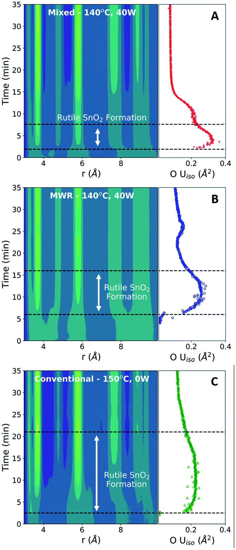 | ||
| Fig. 6 Contour plots of mixed (A), MWR-only (B), and conventional (C) synthesis conditions compared with O Uiso during the same time period. Sharper peaks in the displacement parameter are observed during MWR-assisted synthesis and correspond to an increase in intensity of the first two Sn–Sn peaks. Conventional synthesis results in a broad, lower-intensity peak in Uiso which exists throughout over half the total reaction time. | ||
To further investigate the changes in local structure during phase formation, we utilize a difference PDF method to highlight subtle structural changes.52 The difference PDF, ΔG(r), is given by:
| ΔG(r) = G(r) − G(r)t=0 |
ΔG(r) data is analyzed over the entire reaction time to observe changes in the local atomic structure during synthesis (Fig. 7). For both the MWR-only (blue) and mixed heating (red) conditions, clear shifts in the nearest neighbor Sn–O and Sn–Sn peak positions are observed. The Sn–O peak in MWR-assisted conditions moves to a slightly larger r-value, while the Sn–Sn peak exists at a smaller interatomic distance than the conventionally synthesized SnO2. Additionally, the Sn–Cl/O peak in ΔG(r) becomes negative during MWR-assisted reactions. The Sn–Cl bond distance provides the most significant contribution to this peak, indicating a loss of Sn–Cl bonds in the precursor complex. This is also visible by observing the final Sn–Cl/O peak intensity in G(r) (Fig. S9†). The decrease in Sn–Cl intensity suggests a mechanistic change under EM field exposure in which the Sn–Cl bond in [SnCl6−n(H2O)n]n−2 complexes are involved in phase formation. This differs from the proposed mechanism for conventional hydrothermal synthesis found both here and previously, which indicates that SnO2 crystallizes via reorientation of pre-existing Sn–O octahedra.44 Additional low-intensity peaks also appear in the region near the Sn–Cl peak (2.5–2.9 Å) in MWR-grown samples that are not present during conventional synthesis (dashed box in Fig. 7). Due to the potential overlap of Sn–Cl, Sn–O, and O–O peaks in this r-range, it is difficult to assign specific interatomic distances to these peaks. However, their presence indicates the formation of interatomic correlations not present in conventionally synthesized samples.
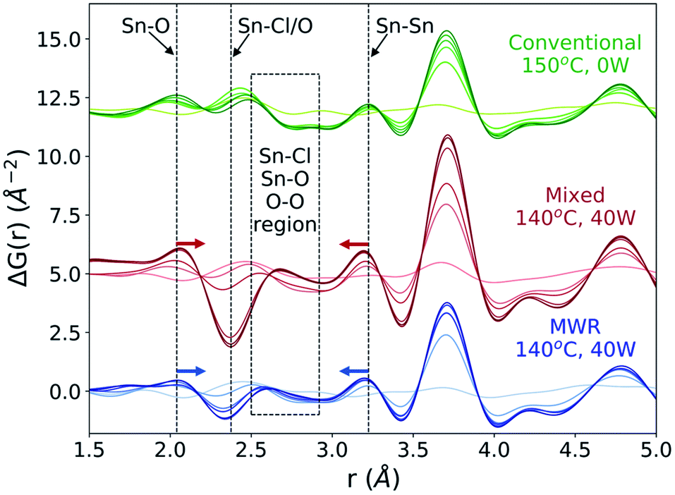 | ||
| Fig. 7 ΔG(r) throughout rutile phase formation for conventional (green), mixed (red), and MWR-only (blue) synthesis conditions. Lighter colors correspond to earlier reaction times, and become darker as the synthesis progresses. Dashed lines indicate the nearest neighbor Sn–O, Sn–Cl/O, and Sn–Sn distances. Shifts in the Sn–O and Sn–Sn peaks for MWR-assisted samples are denoted by colored arrows. The 2.5 to 2.9 Å region (dashed box) displays low-intensity peaks during MWR-assisted conditions which are not present during conventional synthesis. | ||
The changes in Sn–O, Sn–Sn, and Sn–Cl nearest neighbor distances and high rutile O Uiso values during MWR-assisted synthesis indicate a change in the phase formation mechanism relative to conventional hydrothermal synthesis. One potential source of the observed differences is alterations in the local Sn–O coordination environment during rutile phase formation. Generally, tin oxide materials contain structural units with either octahedral or tetrahedral Sn–O coordination. The rutile structure is composed of a mixture of corner and edge-sharing octahedra.53 However, intermediate SnO and Sn3O4 phases have been identified as having tetrahedrally coordinated Sn–O units, which alters the Sn–O and Sn–Sn nearest neighbor distances (Fig. S10 and S11†).54–56 Changes in coordination environment during rutile growth would also require restructuring of oxygen atoms, and could explain the high O Uiso values observed prior to rutile formation.
The Sn3O4 intermediate can also be described by a large amount of ordered oxygen vacancies in the rutile lattice.57 While we do not observe any intermediate phase in our experiments, point defects would impact local Sn–O coordination and alter nearest neighbor distances even without formation of an SnO or Sn3O4 phase. The role of point defects in distorting local atomic structure has been demonstrated in many other oxide materials.58–60 Additionally, oxygen point defects represent a form of static disorder which would lead to high O Uiso values during rutile phase formation. The decrease in the Sn–Cl peak may also be correlated with oxygen atoms leaving the rutile lattice. A decrease in the number of Sn–Cl bonds indicates a transition to higher values of n in the [SnCl6−n(H2O)n]n−2 complexes present in the precursor. Higher n values result in the transition of [SnCl3(H2O)3]+ into a [SnCl2(H2O)4]2+ complex. This transition involves the loss of one Cl atom and the addition of one O atom. While this explanation is certainly over-simplified relative to the true solution chemistry, it provides an example of how oxygen vacancies in the rutile structure could correlate to a decrease in Sn–Cl bonds in the precursor solution.
SnO2 is an n-type semiconductor and is easily reduced, increasing the likelihood that oxygen vacancies could be generated during EM field-assisted synthesis.61–63 Oxygen vacancies in many other oxide systems have also been found to act as nucleation sites promoting phase formation.64–68 Therefore, oxygen vacancy formation provides a plausible explanation for the changes in interatomic distances, high Uiso values, decrease in Sn–Cl peak intensity, and enhanced rutile phase formation observed. This aligns well with prior studies on EM field-assisted methods, which have obtained evidence for oxygen defect-mediated reactions but were not able to characterize the local atomic structure.7,9,17,69,70 Nanoparticle size effects may also influence the local structure and contribute to changes in the interatomic distances in both MWR-assisted and conventionally synthesized SnO2.71–74 The relationship between the size and structural disorder in MWR-assisted nanoparticles warrants further investigation.
The decrease in the Sn–Cl peak intensity and high oxygen displacements observed during EM field exposure invites discussion regarding how an applied EM field may influence specific atomic species relative to conventional heating. While the full impact of EM fields during synthesis remains an open question, the polarizability of specific ions and the atomic structure may contribute. Prior work has demonstrated that Cl and O species are more polarizable than cations such as Sn, which would lead to a stronger interaction with an applied EM field.75,76 Highly electronegative atoms such as O and Cl will also attract electrons relative to Sn, resulting in polarization of the Sn–O or Sn–Cl bond. In a perfect rutile crystal, this polarization will cancel out due to the symmetry of the crystal structure. However, distorted or defective structures which occur during phase formation will impact this symmetry, potentially resulting in more polarizable atomic configurations. Indeed, previous studies have demonstrated that defects in metal oxide crystals can result in increased polarizability and that polarization effects can lower vacancy formation energy.77 This suggests that the polarizability of both the individual ionic species and atomic structure may be important factors underlying EM field-assisted synthesis. Further investigations on the interplay between polarization, charge distribution, applied EM fields, and structural distortions are needed to fully understand the observed effects. However, the results presented here support the notion that local polarizability may be an important factor in understanding structural changes during EM field-assisted synthesis.
4. Conclusion
We demonstrate that EM field-assisted SnO2 nanoparticle growth proceeds along a different synthetic pathway than conventional hydrothermal synthesis. During MWR-assisted synthesis, structural changes on the oxygen sublattice are observed which serve as a precursor to SnO2 crystallization. This is shown via peaks in the oxygen displacement parameter during the early stages of rutile phase formation and changes in Sn–O, Sn–Sn, and Sn–Cl interatomic distances which do not occur during conventional synthesis. The EM field-induced oxygen displacement may be related to point defect formation, which would provide additional nucleation sites for rutile phase formation. This study yields important insight into the mechanisms underlying MWR-assisted synthesis, suggesting that EM fields induce disorder on the oxygen sublattice which mediates the observed phase formation. The use of in situ PDF analysis coupled with the custom-built microwave reactor developed here is critical to gaining this mechanistic insight. This study enables future investigation of EM field-assisted synthetic pathways in a broad range of material systems. Additionally, it represents a step towards utilizing EM fields to design local atomic structure in nanomaterials for applications in renewable energy and catalysis.Conflicts of interest
There are no conflicts of interest to declare.Acknowledgements
MWR-assisted synthesis and characterization of SnO2 nanoparticles in the Jayan group were supported by the U.S. Department of Defense, Air Force Office of Scientific Research (AFOSR) under award number FA9550-17-1-0120. N. N. is supported by a National Defense Science and Engineering Graduate (NDSEG) Fellowship. This research used beamline 28-ID-2 of the National Synchrotron Light Source II, a U.S. Department of Energy (DOE) Office of Science User Facility operated for the DOE Office of Science by Brookhaven National Laboratory under Contract No. DE-SC0012704. The authors would like to thank John Gerling and Jerome Czajkowski of Gerling Applied Engineering, Inc. for their contributions to the manufacturing and design of the microwave waveguide used. The authors also acknowledge John Conturo of Conturo Prototyping, LLC for his contributions to the design and machining of the PTFE parts used to hold borosilicate synthesis tubing inside the microwave waveguide. Additionally, the authors thank John Trunk of Brookhaven National Laboratory for his assistance with experimental beamtime setup and hardware troubleshooting during experiments, and Dr Kyungo Kim of Carnegie Mellon University for his assistance with PDF data collection during beamtime. Lastly, the authors thank Dr Gilles Philippot and Dr Kirsten Jensen for their useful discussions regarding in situ PDF analysis techniques.References
- G. A. Tompsett, W. C. Conner and K. S. Yngvesson, ChemPhysChem, 2006, 7, 296–319 CrossRef CAS PubMed.
- M. Baghbanzadeh, L. Carbone, P. D. Cozzoli and C. O. Kappe, Angew. Chem., Int. Ed., 2011, 50, 11312–11359 CrossRef CAS PubMed.
- S. Komarneni, R. Roy and Q. H. Li, Mater. Res. Bull., 1992, 27, 1393–1405 CrossRef CAS.
- A. Mirzaei and G. Neri, Sens. Actuators, B, 2016, 237, 749–775 CrossRef CAS.
- B. Reeja-Jayan, K. L. Harrison, K. Yang, C.-L. Wang, A. E. Yilmaz and A. Manthiram, Sci. Rep., 2012, 2, 1003 CrossRef CAS PubMed.
- Q. Liu, M. R. Gao, Y. Liu, J. S. Okasinski, Y. Ren and Y. Sun, Nano Lett., 2016, 16, 715–720 CrossRef CAS PubMed.
- S. K. Jha, N. Nakamura, S. Zhang, L. Su, P. M. Smith, X. L. Phuah, H. Wang, H. Wang, J. S. Okasinski, A. J. H. McGaughey and B. Reeja-Jayan, Adv. Eng. Mater., 2019, 21, 1900762 CrossRef CAS.
- N. Nakamura, M. Terban, S. J. L. Billinge and B. Reeja-Jayan, J. Mater. Chem. A, 2017, 5, 18434–18441 RSC.
- S. K. Jha, H. Charalambous, H. Wang, X. L. Phuah, C. Mead, J. Okasinski, H. Wang and T. Tsakalakos, Ceram. Int., 2018, 44, 15362–15369 CrossRef CAS.
- D. S. Wragg, P. J. Byrne, G. Giriat, B. L. Ouay, R. Gyepes, A. Harrison, A. G. Whittaker and R. E. Morris, J. Phys. Chem. C, 2009, 113, 20553–20558 CrossRef CAS.
- T. Muraliganth, K. R. Stroukoff and A. Manthiram, Chem. Mater., 2010, 22, 5754–5761 CrossRef CAS.
- R. Tripathi, G. Popov, X. Sun, D. H. Ryan and L. F. Nazar, J. Mater. Chem. A, 2013, 1, 2990–2994 RSC.
- R. C. Coffin, J. Peet, J. Rogers and G. C. Bazan, Nat. Chem., 2009, 1, 657–661 CrossRef CAS PubMed.
- R. S. Singh, V. K. Rangari, S. Sanagapalli, V. Jayaraman, S. Mahendra and V. P. Singh, Sol. Energy Mater. Sol. Cells, 2004, 82, 315–330 CrossRef CAS.
- U. A. Joshi, J. S. Jang, P. H. Borse and J. S. Lee, Appl. Phys. Lett., 2008, 92, 242106 CrossRef.
- G. Glaspell, L. Fuoco and M. S. El-Shall, J. Phys. Chem. B, 2005, 109, 17350–17355 CrossRef CAS PubMed.
- S. K. Jha, X. L. Phuah, J. Luo, C. P. Grigoropoulos, H. Wang, E. García and B. Reeja-Jayan, J. Am. Ceram. Soc., 2019, 102, 5–31 CAS.
- A. de la Hoz, Á. Díaz-Ortiz and A. Moreno, Chem. Soc. Rev., 2005, 34, 164–178 RSC.
- Y. Li and W. Yang, J. Membr. Sci., 2008, 316, 3–17 CrossRef CAS.
- A. de la Hoz, A. Díaz-Ortiz and A. Moreno, Journal of Microwave Power and Electromagnetic Energy, 2006, 41, 45–66 Search PubMed.
- S. J. L. Billinge and M. G. Kanatzidis, Chem. Commun., 2004, 749–760 RSC.
- T. Egami and S. J. L. Billinge, Underneath the Bragg Peaks: Structural Analysis of Complex Materials, Elsevier, 2012 Search PubMed.
- K. M. Ø. Jensen, H. L. Andersen, C. Tyrsted, E. D. Bøjesen, A.-C. Dippel, N. Lock, S. J. L. Billinge, B. B. Iversen and M. Christensen, ACS Nano, 2014, 8, 10704–10714 CrossRef CAS PubMed.
- D. Saha, K. M. Ø. Jensen, C. Tyrsted, E. D. Bøjesen, A. H. Mamakhel, A.-C. Dippel, M. Christensen and B. B. Iversen, Angew. Chem., Int. Ed., 2014, 53, 3667–3670 CrossRef CAS PubMed.
- C. Tyrsted, N. Lock, K. M. Ø. Jensen, M. Christensen, E. D. Bøjesen, H. Emerich, G. Vaughan, S. J. L. Billinge and B. B. Iversen, IUCrJ, 2014, 1, 165–171 CrossRef CAS PubMed.
- P. J. Chupas, K. W. Chapman, G. Jennings, P. L. Lee and C. P. Grey, J. Am. Chem. Soc., 2007, 129, 13822–13824 CrossRef CAS PubMed.
- C. Tyrsted, K. M. Ø. Jensen, E. D. Bøjesen, N. Lock, M. Christensen, S. J. L. Billinge and B. Brummerstedt Iversen, Angew. Chem., Int. Ed., 2012, 51, 9030–9033 CrossRef CAS PubMed.
- S. Tominaka, H. Yamada, S. Hiroi, S. I. Kawaguchi and K. Ohara, ACS Omega, 2018, 3, 8874–8881 CrossRef CAS PubMed.
- H. Yamada, S. Tominaka, K. Ohara, Z. Liu, T. Okubo and T. Wakihara, J. Phys. Chem. C, 2019, 123, 28419–28426 CrossRef CAS.
- M. Gateshki, S. Yin, Y. Ren and V. Petkov, Chem. Mater., 2007, 19, 2512–2518 CrossRef CAS.
- K. Byrappa and T. Adschiri, Prog. Cryst. Growth Charact., 2007, 53, 117–166 CrossRef CAS.
- E. R. Leite, I. T. Weber, E. Longo and J. A. Varela, Adv. Mater., 2000, 12, 965–968 CrossRef CAS.
- A. Diéguez, A. Romano-Rodríguez, J. R. Morante, U. Weimar, M. Schweizer-Berberich and W. Göpel, Sens. Actuators, B, 1996, 31, 1–8 CrossRef.
- Y. Liu, Y. Jiao, Z. Zhang, F. Qu, A. Umar and X. Wu, ACS Appl. Mater. Interfaces, 2014, 6, 2174–2184 CrossRef CAS PubMed.
- M. S. Park, G. X. Wang, Y. M. Kang, D. Wexler, S. X. Dou and H. K. Liu, Angew. Chem., Int. Ed., 2007, 46, 750–753 CrossRef CAS PubMed.
- D. Deng and J. Y. Lee, Chem. Mater., 2008, 20, 1841–1846 CrossRef CAS.
- L. Jiang, G. Sun, Z. Zhou, S. Sun, Q. Wang, S. Yan, H. Li, J. Tian, J. Guo, B. Zhou and Q. Xin, J. Phys. Chem. B, 2005, 109, 8774–8778 CrossRef CAS PubMed.
- J. Becker, M. Bremholm, C. Tyrsted, B. Pauw, K. M. Ø. Jensen, J. Eltzholt, M. Christensen and B. B. Iversen, J. Appl. Crystallogr., 2010, 43, 729–736 CrossRef CAS.
- M. Bremholm, H. Jensen, S. B. Iversen and B. B. Iversen, J. Supercrit. Fluids, 2008, 44, 385–390 CrossRef CAS.
- P. J. Chupas, X. Qiu, J. C. Hanson, P. L. Lee, C. P. Grey and S. J. L. Billinge, J. Appl. Crystallogr., 2003, 36, 1342–1347 CrossRef CAS.
- A. P. Hammersley, S. O. Svensson, M. Hanfland, A. N. Fitch and D. Hausermann, High Pres. Res., 1996, 14, 235–248 CrossRef.
- P. Juhás, T. Davis, C. L. Farrow and S. J. L. Billinge, J. Appl. Crystallogr., 2013, 46, 560–566 CrossRef.
- P. Juhas, C. L. Farrow, X. Yang, K. R. Knox and S. J. L. Billinge, Acta Crystallogr., Sect. A: Cryst. Phys., Diffr., Theor. Gen. Crystallogr., 2015, 71, 562–568 CrossRef PubMed.
- K. M. Ø. Jensen, M. Christensen, P. Juhas, C. Tyrsted, E. D. Bøjesen, N. Lock, S. J. L. Billinge and B. B. Iversen, J. Am. Chem. Soc., 2012, 134, 6785–6792 CrossRef CAS PubMed.
- M. J. Taylor and J. M. Coddington, Polyhedron, 1992, 11, 1531–1544 CrossRef CAS.
- P. Juhás, D. M. Cherba, P. M. Duxbury, W. F. Punch and S. J. L. Billinge, Nature, 2006, 440, 655–658 CrossRef PubMed.
- D. Prill, P. Juhas, M. U. Schmidt and S. J. L. Billinge, J. Appl. Crystallogr., 2015, 48, 171–178 CrossRef CAS.
- I. K. Jeong, T. Proffen, F. Mohiuddin-Jacobs and S. J. L. Billinge, J. Phys. Chem. A, 1999, 103, 921–924 CrossRef CAS.
- K. Kodama, S. Iikubo, T. Taguchi and S. Shamoto, Acta Crystallogr., Sect. A: Cryst. Phys., Diffr., Theor. Gen. Crystallogr., 2006, 62, 444–453 CrossRef PubMed.
- E. A. Meulenkamp, J. Phys. Chem. B, 1998, 102, 5566–5572 CrossRef CAS.
- L. Gamez-Mendoza, M. W. Terban, S. J. L. Billinge and M. Martinez-Inesta, J. Appl. Crystallogr., 2017, 50, 741–748 CrossRef CAS.
- C. K. Christensen, E. D. Bøjesen, D. R. Sørensen, J. H. Kristensen, J. K. Mathiesen, B. B. Iversen and D. B. Ravnsbæk, ACS Appl. Nano Mater., 2018, 1, 5071–5082 CrossRef CAS.
- A. A. Bolzan, C. Fong, B. J. Kennedy and C. J. Howard, Acta Crystallogr., Sect. B: Struct. Sci., 1997, 53, 373–380 CrossRef.
- F. Lawson, Nature, 1967, 215, 955–956 CrossRef CAS.
- J. Köhler, J. Tong, R. Dinnebier and A. Simon, Z. Anorg. Allg. Chem., 2012, 638, 1970–1975 CrossRef.
- B. Eifert, M. Becker, C. T. Reindl, M. Giar, L. Zheng, A. Polity, Y. He, C. Heiliger and P. J. Klar, Phys. Rev. Mater., 2017, 1, 014602 CrossRef.
- A. Seko, A. Togo, F. Oba and I. Tanaka, Phys. Rev. Lett., 2008, 100, 045702 CrossRef PubMed.
- S. Fabris, A. T. Paxton and M. W. Finnis, Acta Mater., 2002, 50, 5171–5178 CrossRef CAS.
- H. Peng, Phys. Lett. A, 2008, 372, 1527–1530 CrossRef CAS.
- F. Wang, C. Di Valentin and G. Pacchioni, Phys. Rev. B: Condens. Matter Mater. Phys., 2011, 84, 073103 CrossRef.
- Z. M. Jarzebski and J. P. Marton, J. Electrochem. Soc., 1976, 123, 199C CrossRef CAS.
- A. Bouzoubaa, A. Markovits, M. Calatayud and C. Minot, Surf. Sci., 2005, 583, 107–117 CrossRef CAS.
- K. G. Godinho, A. Walsh and G. W. Watson, J. Phys. Chem. C, 2009, 113, 439–448 CrossRef CAS.
- D. A. H. Hanaor and C. C. Sorrell, J. Mater. Sci., 2011, 46, 855–874 CrossRef CAS.
- G. Pacchioni, ChemPhysChem, 2003, 4, 1041–1047 CrossRef CAS PubMed.
- R. D. Shannon and J. A. Pask, J. Am. Ceram. Soc., 1965, 48, 391–398 CrossRef CAS.
- B. Choudhury and A. Choudhury, Int. Nano Lett., 2013, 3, 55 CrossRef.
- E. U. Donev, J. I. Ziegler, R. F. Haglund Jr and L. C. Feldman, J. Opt, 2009, 11, 125002 Search PubMed.
- J. M. Lebrun, C. S. Hellberg, S. K. Jha, W. M. Kriven, A. Steveson, K. C. Seymour, N. Bernstein, S. C. Erwin and R. Raj, J. Am. Ceram. Soc., 2017, 100, 4965–4970 CrossRef CAS.
- B. Yoon, D. Yadav, R. Raj, E. P. Sortino, S. Ghose, P. Sarin and D. Shoemaker, J. Am. Ceram. Soc., 2018, 101, 1811–1817 CrossRef CAS.
- B. Gilbert, F. Huang, H. Zhang, G. A. Waychunas and J. F. Banfield, Science, 2004, 305, 651 CrossRef CAS PubMed.
- V. V. T. Doan-Nguyen, S. A. J. Kimber, D. Pontoni, D. Reifsnyder Hickey, B. T. Diroll, X. Yang, M. Miglierini, C. B. Murray and S. J. L. Billinge, ACS Nano, 2014, 8, 6163–6170 CrossRef CAS PubMed.
- T. L. Christiansen, E. D. Bøjesen, M. Juelsholt, J. Etheridge and K. M. Ø. Jensen, ACS Nano, 2019, 13, 8725–8735 CrossRef CAS PubMed.
- A. S. Masadeh, E. S. Božin, C. L. Farrow, G. Paglia, P. Juhas, S. J. L. Billinge, A. Karkamkar and M. G. Kanatzidis, Phys. Rev. B, 2007, 76, 115413 CrossRef.
- C. R. A. Catlow, K. M. Diller and M. J. Norgett, J. Phys. C: Solid State Phys., 1977, 10, 1395–1412 CrossRef CAS.
- G. V. Lewis and C. R. A. Catlow, J. Phys. C: Solid State Phys., 1985, 18, 1149–1161 CrossRef CAS.
- M. Youssef, K. J. Van Vliet and B. Yildiz, Phys. Rev. Lett., 2017, 119, 126002 CrossRef PubMed.
Footnote |
| † Electronic supplementary information (ESI) available. See DOI: 10.1039/d0ta03721d |
| This journal is © The Royal Society of Chemistry 2020 |