
 Open Access Article
 This Open Access Article is licensed under a
 Creative Commons Attribution 3.0 Unported Licence
Fatigue resistant lead-free multilayer ceramic capacitors with ultrahigh energy density†
Ge
Wang‡
 a,
Zhilun
Lu‡
ab,
Huijing
Yang‡
ac,
Hongfen
Ji‡
ad,
Ali
Mostaed
ae,
Linhao
Li
a,
Yiqi
Wei
a,
Antonio
Feteira
f,
Shikuan
Sun
a,
Derek C.
Sinclair
a,
Dawei
Wang
*a and
Ian M.
Reaney
a
a,
Zhilun
Lu‡
ab,
Huijing
Yang‡
ac,
Hongfen
Ji‡
ad,
Ali
Mostaed
ae,
Linhao
Li
a,
Yiqi
Wei
a,
Antonio
Feteira
f,
Shikuan
Sun
a,
Derek C.
Sinclair
a,
Dawei
Wang
*a and
Ian M.
Reaney
a
aDepartment of Materials Science and Engineering, University of Sheffield, Sheffield, S1 3JD, UK. E-mail: dawei.wang@sheffield.ac.uk
bThe Henry Royce Institute, Sir Robert Hadfield Building, Sheffield, S1 3JD, UK
cDepartment of Physics, Tangshan Normal University, Tangshan 063000, China
dLaboratory of Thin Film Techniques and Optical Test, Xi'an Technological University, Xi'an 710032, China
eDepartment of Materials, University of Oxford, Parks Road, Oxford OX1 3PH, UK
fChristian Doppler Laboratory for Advanced Ferroic Oxides, Sheffield Hallam University, Sheffield, S1 1WB, UK
First published on 12th May 2020
Abstract
The critical role of electrical homogeneity in optimising electric-field breakdown strength (BDS) and energy storage in high energy density (0.7 − x)BiFeO3–0.3BaTiO3–xBi(Li0.5Nb0.5)O3 (BF–BT–xBLN) lead-free capacitors is demonstrated. The high BDS for bulk ceramics and multilayers (dielectric layer thickness ∼ 8 μm) of ∼260 and ∼950 kV cm−1, respectively, gives rise to record-performance of recoverable energy density, Wrec = 13.8 J cm−3 and efficiency, η = 81%. Under an electric field of 400 kV cm−1, multilayers are temperature stable up to 100 °C, frequency independent in the range 10−2 to 102 Hz, have low strain (<0.03%) and are fatigue-resistant up to 104 cycles (Wrec variation < 10%). These properties show promise for practical use in pulsed power systems.
Introduction
The depletion of fossil fuel reserves and serious concerns over climate change have provoked the development of renewable energy including tidal, wind and solar.1–5 Electrical energy is currently stored or generated autonomously through a range of devices such as fuel cells and batteries.1–3,6–13 For energy storage applications, dielectric capacitors have the advantages of fast charging–discharging speed, superior temperature stability and are mainly used for pulsed power applications such as power distribution, medical transportation devices and pulsed power weapons.4,5,14–18 Dielectric polymers are limited by their low melting temperatures and related degradation.1,2 Dielectric ceramics are potentially more temperature stable than dielectric polymers but have comparatively low recoverable energy density (Wrec) and energy conversion efficiency (η), due to their low electric-field breakdown strength (BDS) and high energy loss (Wloss).To satisfy the requirements of power supply components in portable electronics, electric vehicles and other high power and energy storage applications, both high Wrec and η are required. For dielectric capacitors, the total energy density (W), Wrec and η are given by:
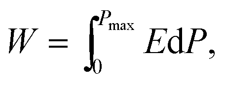 | (1) |
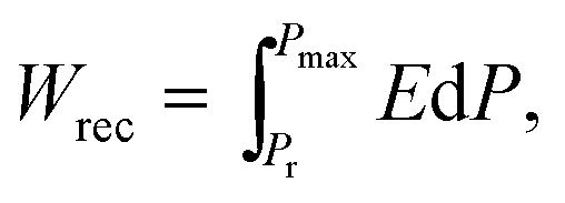 | (2) |
| η = Wrec/W | (3) |
Although high energy storage performance with Wrec ∼ 10.4 J cm−3 and a η ∼ 87% has been achieved with La and Sn co-doped lead zirconate at 400 kV cm−1,23 lead-free ceramics based on AgNbO3 (AN), BaTiO3 (BT), (Bi0.5Na0.5)TiO3 (BNT), (K0.5Na0.5)NbO3 (KNN) and BiFeO3–BaTiO3 (BF–BT) have all been studied due to concerns over the toxicity of lead.24–56 High Wrec (>3 J cm−3) has been reported in antiferroelectric (AFE) (Ta, La and Gd)-doped AN with enhanced BDS up to 300 kV cm−1.24–28 Oxide additives (Al2O3, SiO2, MgO) and Bi(A,B)O3 (A = Li, Mg and Zn, B = Nb, Ta, Ti and Zr) have all been found to improve Wrec and BDS of BT-based ceramics up to 2.9 J cm−3 and 300 kV cm−1, respectively.29–36 Recently, Wrec ∼ 7 J cm−3 with high η ∼ 85% was reported in NaNbO3-doped BNT37 at 390 kV cm−1 and Wrec ∼ 4 J cm−3 were also obtained for KNN-based ceramics due to enhancement of BDS (300–400 kV cm−1) by controlled grain growth.46–49
(1 − x)BF–xBT materials initially drew attention as potential lead-free piezoelectrics with high piezoelectric coefficient (d33) ∼ 402 pC N−1, normalised strain  ∼ 600 pm V−1 and Curie temperature (Tc) ∼ 454 °C in a mixed-phase region of rhombohedral and pseudocubic with x = 0.25 to 0.35.57,58 The mixture of highly polarisable ions such as Bi3+ and Ti4+ in a matrix of dissimilar sized ABO3, perovskite unit cells is considered responsible for its strong piezoelectric/electrostrictive response.59 These crystallo-chemical features are also considered ideal for optimising polarisation within a pseudocubic relaxor phase and thus provide a base from which to devise materials with high energy density. For example, BF–BT based compositions with various dopants such as Nd and A(B1,B2)O3 (A = Bi and Nd, B1 = Zn and Mg, B2 = Nb and Zr),50–56 have all been shown to exhibit high energy density. The best compositions to date however, are doped with Nd(Zn1/2Zr1/2)O3 and give Wrec ∼ 2.5 J cm−3 with BDS >260 kV cm−1 for ceramics which improve dramatically when multilayered to 10.5 J cm−3 at 700 kV cm−1.56
Enhancement of BDS in dielectric materials is an effective approach to optimize Wrec, and is associated with factors such as the band gap, reduced porosity, grain size, impurity concentrations, sample thickness/geometry and space-charging polarization.60 However, practically, BDS is limited in many materials by the presence of conductive pathways, e.g. from core to core or from shell to shell, which appear as electrical inhomogeneity in impedance spectroscopy (IS) data.61–63
The relationship between BDS and dielectric layer thickness was first published by Gerson and Marshall in 1959.64 In principle, all solid dielectrics increase their BDS with decreasing layer thickness, culminating in values of >1 mV cm−1 for thin films.65 In our own research, we have demonstrated this effect numerous times, as have several research groups, by fabricating multilayer capacitors (10 μm dielectric layer thickness) once good properties (high resistivity and electrical homogeneity) have been demonstrated in bulk ceramics.51,56 However, with any given multilayer, short circuit pathways can emerge between low resistivity regions as layer thickness decreases, thereby decreasing BDS. The caveat therefore, which must be applied to the Gerson and Marshall64 relationship is that BDS will only increase if low resistivity pathways are eliminated, i.e. the materials have high resistivity and are electrically homogeneous.
In this study, we utilise stoichiometric doping, the nature of which is complex but which has been dealt with by Sinclair and co-workers for several systems, e.g. BNT-based,66–68 and BF–BT-based69–71 materials. Stoichiometric doping has been shown to be effective at reducing conductivity and promoting electrical homogeneity in a wide range of systems.50,56,67,68 By eliminating extrinsic effects through electrical homogeneity, we enable the Gerson and Marshall effect (Fig. 1), resulting in Wrec ∼ 13.8 J cm−3 at ∼950 kV cm−1 in 0.57BiFeO3–0.30BaTiO3–0.13Bi(Li0.5Nb0.5)O3 (BF–BT–0.13BLN) ceramic multilayers. Furthermore, excellent fatigue properties with respect to temperature, frequency and cyclic poling are demonstrated, which play a critical role in practical applications.
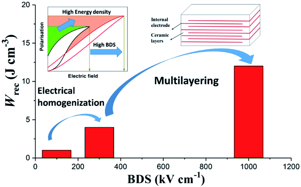 | ||
| Fig. 1 Schematic representation of the approach for optimisation of BDS and Wrec by electrical homogenization and multilayering. | ||
Results and discussion
High energy density dielectric ceramics
The crystal structure of crushed BF–BT–xBLN ceramics (0.00 ≤ x ≤ 0.15) was determined using X-ray powder diffraction (XRD), as shown in Fig. 2a. XRD patterns are indexed as a single-phase perovskite phase without any detectable secondary impurity phases for x < 0.08. Impurity peaks are observed for x ≥ 0.08 at which point in the composition, the solid solubility limit of Li0.5Nb0.5 on the B-site of BF–BT is exceeded. The average ionic radii (R) of (Li0.5Nb0.5)3+ ions are given by R = 0.5R(Li+) + 0.5R(Nb5+) = 0.70 Å (0.76 Å and 0.64 Å are the respective ionic radii of Li+ and Nb5+in six-fold coordination), which is larger than that of Fe3+ and Ti4+ (0.645 and 0.605 Å, respectively) in the same co-ordination.72 As x increases therefore, diffraction peaks shift left, commensurate with an increase in lattice parameter (Fig. S1, ESI†). A full-pattern Rietveld refinement on XRD data for BF–BT–0.13BLN ceramics has been conducted using TOPAS 5. The best fitting was obtained using a mixed-phase assemblage of R3c rhombohedral (14%) and Pm![[3 with combining macron]](https://www.rsc.org/images/entities/char_0033_0304.gif) m cubic phase (86%), as displayed in Fig. S2 and Table S1 (ESI†), consistent with previous reports on BF–BT ternary systems.50,51,56,73,76
m cubic phase (86%), as displayed in Fig. S2 and Table S1 (ESI†), consistent with previous reports on BF–BT ternary systems.50,51,56,73,76
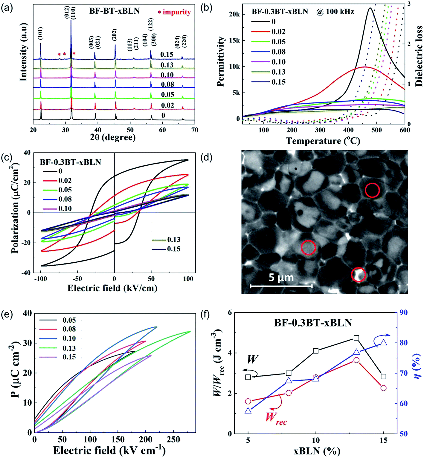 | ||
| Fig. 2 (a) XRD patterns for BF–BT–xBLN (x = 0.00–0.15). (b) Temperature-dependent permittivity and dielectric loss data for BF–BT–xBLN ceramics at a frequency of 100 kHz. (c) Bipolar P–E loops for BF–BT–xBLN ceramics (d) EDS elemental spot analysis (circled) for BF–BT–0.13BLN ceramics. (e) Unipolar P–E loops under Emax and (f) energy storage properties under Emax for BF–BT–xBLN ceramics. | ||
The temperature-dependent permittivity (εrvs. T) and dielectric loss (tan![[thin space (1/6-em)]](https://www.rsc.org/images/entities/char_2009.gif) δ vs. T) data at 100 kHz for BF–BT–xBLN ceramics are presented in Fig. 2b. A single sharp peak at a Tc of ∼480 °C is observed for undoped BF–BT, associated with a ferroelectric to paraelectric transition. As the BLN concentration increasing, the dielectric maxima broadens, accompanied by a lowering of the maximum value of εr. Broad frequency-dependent εr – T peaks are obtained for compositions with x > 0.02, as displayed in Fig. S3 (ESI†), indicating a compositionally driven transition from dominantly ferroelectric to relaxor behaviour. Despite these changes, low values of tanδ are recorded in all samples below 250 °C but increase substantially above this temperature. There is however, no systematic trend in the dielectric loss above 250 °C with increasing x. There will be increasing contributions from space charge (long range conduction) to the loss but bulk conductivity values obtained from impedance spectroscopy data do not support a simple hypothesis of increasing oxygen vacancies with BLN content, as illustrated in Fig. S4 (ESI†). In fact, the bulk conductivity is lower in x = 0.15 than it is for lower x values.
δ vs. T) data at 100 kHz for BF–BT–xBLN ceramics are presented in Fig. 2b. A single sharp peak at a Tc of ∼480 °C is observed for undoped BF–BT, associated with a ferroelectric to paraelectric transition. As the BLN concentration increasing, the dielectric maxima broadens, accompanied by a lowering of the maximum value of εr. Broad frequency-dependent εr – T peaks are obtained for compositions with x > 0.02, as displayed in Fig. S3 (ESI†), indicating a compositionally driven transition from dominantly ferroelectric to relaxor behaviour. Despite these changes, low values of tanδ are recorded in all samples below 250 °C but increase substantially above this temperature. There is however, no systematic trend in the dielectric loss above 250 °C with increasing x. There will be increasing contributions from space charge (long range conduction) to the loss but bulk conductivity values obtained from impedance spectroscopy data do not support a simple hypothesis of increasing oxygen vacancies with BLN content, as illustrated in Fig. S4 (ESI†). In fact, the bulk conductivity is lower in x = 0.15 than it is for lower x values.
The activation energy for total conductivity (Fig. S4, ESI†) remains broadly the same for all compositions suggesting the conduction mechanism (but not necessarily) remains the same as dopant concentration increases. Conductivity remains via VO diffusion throughout consistent with an activation energy of ∼1.1–1.2 eV and points to substitution/compensation in accordance with the batched stoichiometry.67 However, the site location of Li may locally play a role in the defect chemistry and is an area of future work.
From Fig. 2b, x = 0 shows classic paraelectric behaviour above Tc at 480 °C whereas with increasing x, εr in the range 480–600 °C broadens and becomes relaxor-like. As a consequence, a significant contribution to the loss must still be associated with polarisation rotation/coalescence of polar nano regions (relaxor behaviour) at higher values of x. Polarization-electric field (P–E) loops obtained at 100 kV cm−1 for BF–BT–xBLN ceramics are displayed in Fig. 2c. The highest polarization values are recorded for undoped BF–BT with Pmax ∼ 34 μC cm−2 and Pr ∼ 25 μC cm−2. P–E loops become slimmer and are no longer saturated as increasing BLN concentration, along with a continuous reduction of Pmax, Pr and EC (Fig. S5, ESI†), typical of a transition from ferroelectric to relaxor behaviour.
The scanning and backscattered electron microscopy (SEM and BSE) images for BF–BT–xBLN ceramics are displayed in Fig. S6 and S7 (ESI†). The largest grain size (∼8 μm) is observed for undoped BF–BT. For BLN-doped compositions, the grain size reduces significantly (Fig. S6 and S7, ESI†) accompanied by the formation of a core–shell microstructure, exhibiting Bi/Fe-rich (bright), Ba-rich (dark) regions and Bi-rich (bright GB phase) via energy dispersive X-ray spectroscopy (EDS) analysis, Fig. 2d and Table S2 (ESI†). The bright grain boundary phase is Bi-rich, consistent with impurity peaks in XRD pattern.
The formation of the core–shell structure is driven by immiscibilty of the perovskite end members which not only have dissimilar ion size, e.g. Ba2+ >> Bi3+ but have different bonding with Bi3+ being dominantly covalent whereas Ba2+ is considered ionic. Immiscibility in part can be suppressed by quenching and by careful selection of dopants.70,71,74–76 The core–shell structure in BF–BT–0.13BLN ceramics was investigated further by transmission electron microscopy (TEM) (Fig. S8, ESI†) and exhibits small tweed domains (core) and a shell of nanodomains, similar to previous reports in BF–BT-based ceramics.51,56,74–76
The grain size for BF–BT–xBLN ceramics decreases from ∼8.2 ± 0.5 μm for x = 0.00 to 1.1 ± 0.2 μm for x = 0.05 and then increases slightly to 2.0 ± 0.2 μm for x = 0.15. The grain size for the optimized composition, BF–BT–0.13BLN, is 1.5 ± 0.2 μm. The major change in grain size therefore, occurs between 0 < x < 0.05. A sudden decrease in grain size with dopants is common in solid solutions and may be attributed to an increase of grain boundary drag, related to the incorporation of a high valence species such as Nb.47,48,77,78 The similar grain size for all subsequent compositions for x > 0.05 indicates that it is not a critical factor in optimising the energy density in ceramics as x increases. However, for multilayers with ∼8 μm layer thickness the decrease from ∼8 to ∼1–2 μm is important as it ensures there are multiple grains rather than a single grain separating the electrodes and thereby eliminating the potential of short circuit conduction pathways and maintaining a high BDS.
Energy storage properties are obtained using unipolar P–E loops up to the maximum electric field (Emax). Due to low BDS (<120 kV cm−1) and high energy loss, compositions with x ≤ 0.02 (Fig. 2c) are not considered desirable for energy storage applications. Compositions with 0.05 ≤ x ≤ 0.15 with a strong core–shell contrast exhibits greater potential for energy storage and are considered for further characterization. The unipolar P–E loops of BF–BT–xBLN (0.05 ≤ x ≤ 0.15) under Emax are displayed in Fig. 2e and S9 (ESI†), with corresponding values of Pmax, Pr, ΔP and Emax given in Fig. S10 (ESI†). With increasing electric field, Pmax, and ΔP increase linearly with a slight improvement of Pr (Fig. S10a–e, ESI†). ΔP and Emax increase initially and then decrease after reaching a maximum of ΔP ∼ 32.5 μC cm−2 for x = 0.10 and Emax ∼ 260 kV cm−1 for x = 0.13, respectively (Fig. S10f, ESI†). W, Wrec and η at different electric fields are calculated according to eqn (1)–(3) and presented in Fig. S11 (ESI†). At Emax, the highest W (4.74 J cm−3) and Wrec (3.64 J cm−3) are obtained for x = 0.13 ceramics, while the highest η (∼80%) is attained for x = 0.15 ceramics, as illustrated in Fig. 2f.
The electrical microstructure of BF–BT–xBLN ceramics is investigated by impedance spectroscopy (IS) as a function of temperature and frequency. The spectroscopic plots of Z′′ and M′′ at 250 °C for BF–BT–xBLN with x = 0.00 and x = 0.13 are shown in Fig. 3. For undoped BF–BT, two electrical components are observed in the M′′ spectra with capacitances (C) of ∼6.83 × 10⁻¹⁰ and 1.24 × 10⁻⁹ F cm−1, at 80 Hz and 10 kHz (Fig. 3a), respectively. These peaks are temperature dependent, both decrease in height (and therefore increased in capacitance, as shown in Fig. S4, ESI†) with increasing temperature in the range ∼250–400 °C. This is consistent with the εr – T data in this range, Fig. 2a, and indicates both elements are consistent with ferroelectric-type regions below Tc. The C values obtained from the M′′ peaks in the spectra are consistent with bulk-type responses for these polar ceramics and the large separation in their maximum frequency (fmax) values indicate components with a large difference in resistance (R), therefore suggesting the grains are electrically inhomogeneous. Equivalent circuit-fitting (to a first approximation) to a model based on two parallel resistor–capacitor (RC) elements connected in series gave plausible temperature-dependent permittivity and conductivity values (see ESI, Fig. S4 and S12,† respectively) that are consistent with a conductive-core and resistive-shell type electrical microstructure. A resistivity of ∼1.9 MΩ cm is obtained from the Z′′-f spectroscopic plot for the lower frequency (shell) component at ∼80 Hz which dominates the Z′′-f spectrum; an accurate estimate for the resistivity of the higher frequency (core) component cannot be obtained from the Z′′-f spectrum but is calculated to be ∼1.3 kΩ cm using the relationship ωRC = 1 (where ω = 2πf, with f in Hz) from the second, higher frequency M′′ peak at 10 kHz.56,62 With increasing BLN concentration, the higher frequency M′′ peak associated with the core-type response remains clearly visible for x < 0.08; however, for 0.08 ≤ x ≤ 0.15 its presence has visibly decreased and is absent for x ≥ 0.13, Fig. S13 and S14 (ESI†). The large Z′′ spectroscopic peak remains at ∼100 Hz with increasing BLN content, however its magnitude increases from ∼2 to 3 MΩ cm, Fig. S13 (ESI†).
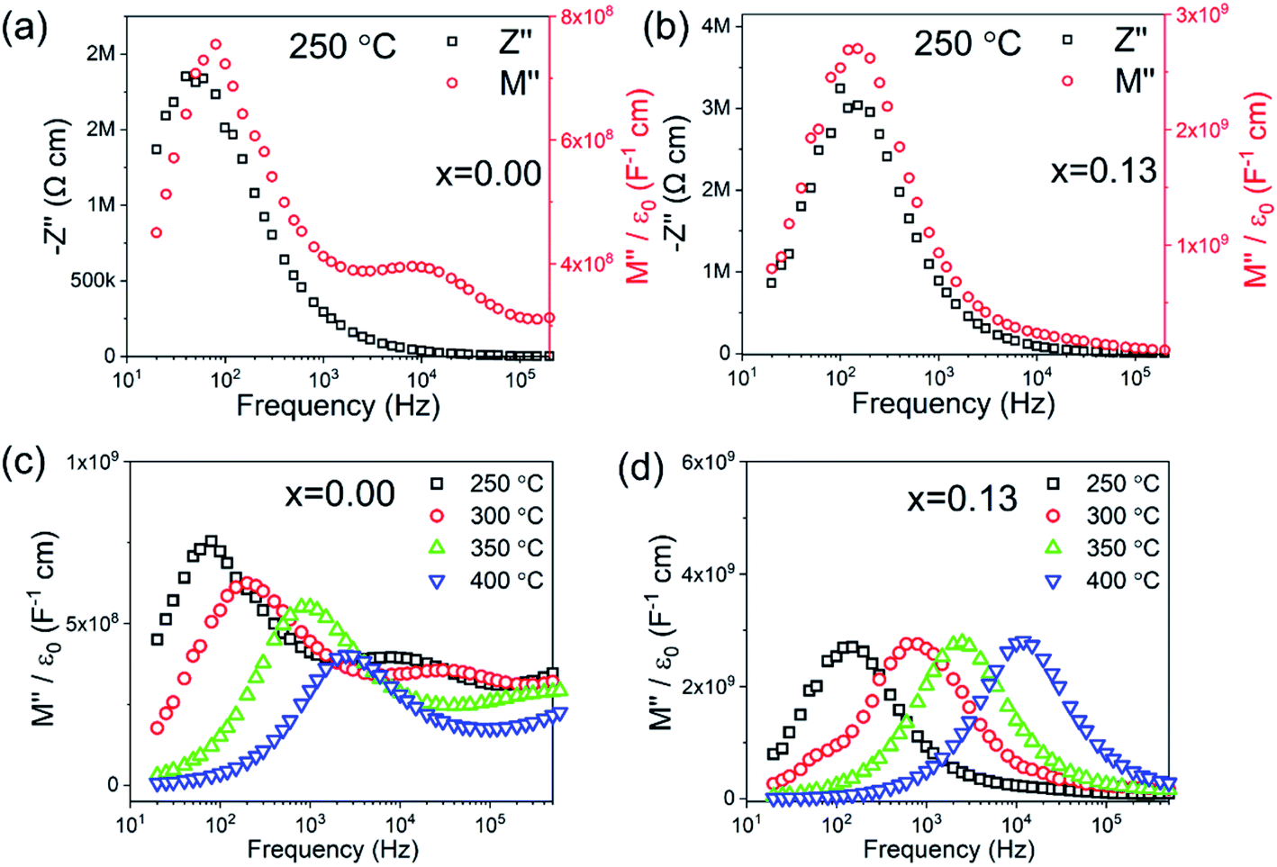 | ||
| Fig. 3 Combined Z′′ and M′′ spectroscopic plots at 250 °C of BT–0.3BT–xBLN for x= (a) 0.00 and (b) 0.13; temperature-dependent M′′ spectroscopic plots for x= (c) 0.00 and (d) 0.13. | ||
Only a single peak is observed in the spectroscopic plots of Z′′ and M′′ at 250 °C for x = 0.13 (Fig. 3b), corresponding to a single bulk component with C ∼ 1.68 × 10⁻¹⁰ F cm−1 (from the M′′ peak) and resistivity, R of ∼6 MΩ cm (from the Z′′ peak). It is noteworthy that the M′′ peak height is largely invariant in the temperature range ∼250–400 °C (Fig. 3d) which is consistent with the flat εr – T response observed from fixed frequency dielectric measurements in Fig. 2b. Temperature-dependent spectroscopic plots of M′′ for x = 0.00 and x = 0.13 are displayed in Fig. 3c and d. The high-frequency conductive component observed for x = 0.00 can only be observed below 350 °C due to its time constant (RC product) exceeding the upper frequency range measured in our experiments. The magnitude and temperature dependence of C values from the M′′ peaks confirm the predominantly ferroelectric nature of core and shell components in x = 0 and overall relaxor-ferroelectric behaviour in the electrically homogeneous grains of x = 0.13. The IS data indicates that short circuit conduction paths are more likely to form under high field for x < 0.08 via the conductive grain cores, however, for x > 0.08, enhanced BDS as well as Wrec can be achieved due to improved electrical homogeneity with a much lower volume fraction of conductive cores.
Multilayer ceramic capacitors (MLCCs)
To increase the BDS and energy storage properties, multilayer ceramic capacitors of BF–BT–0.13BLN were fabricated with ∼8 μm thick dielectric layers with active electrode area of 5 mm2, as presented in Fig. 4a and b.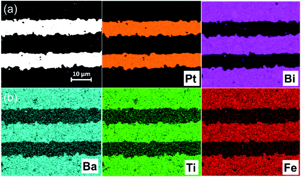 | ||
| Fig. 4 (a) BSE cross section micrographs of BF–BT–0.13BLN multilayer MLCCs; (b) EDS mapping of each elemental metal distribution. | ||
Fig. 5a shows a TEM image obtained from the interface between the BF–BT–0.13BLN ceramic and Pt electrode. According to the selected area electron diffraction (SAED) patterns in Fig. 5b and (c), the {001} atomic planes of the ceramic grain displayed in Fig. 5a are ∼4° off parallel to Pt{115} but we do not suggest that this is due an epitaxial relation as the multilayers are formed by a powder-based tape-cast process. Consistent with XRD results, the SAED patterns displayed in Fig. 5b and S15 (ESI†) obtained from the BF–BT–13BLN ceramic along [210] and [100] zone axes, respectively, indicating they are perovskite structured. An amorphous layer (∼4 nm) is observed at the interface between the Pt and the ceramic. The role of the amorphous layer is not detrimental to energy storage properties and may have a positive effect on breakdown strength through moderating field concentrations at the electrode/dielectric interface and on polarization through a space-charge mechanism. According to EDS elemental maps presented in Fig. 5d, the amorphous layer is rich in Ba, Ti and Fe but deficient in Bi. Bi however, is present at the surface of the Pt. Similar amorphous layers have been reported in BT-based MLCCs and their formation attributed to binder (carbon-related) burnout during the sintering process.34 Potentially this layer can be suppressed by slower or longer binder burnout stages during sintering of the devices.
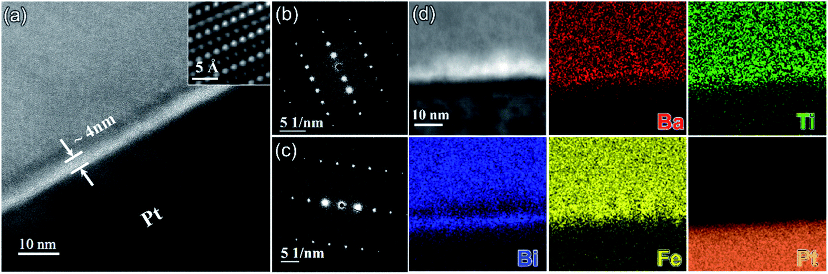 | ||
| Fig. 5 (a) TEM micrograph obtained from an interface between a BF–BT–0.13BLN grain and a Pt grain (electrode). Here the Pt grain is close to its [321] zone axis and the BF–BT–0.13BLN grain is ∼4° off from its [210] zone axis; inset shows an high resolution transmission electron microscopy (HRTEM) image (filtered) obtained from the BF–BT–0.13BLN grain at a higher magnification. (b) <210> SAED pattern obtained from the BF–BT–0.13BLN grain displayed in (a). (c) <321> SAED pattern obtained from the Pt grain displayed in (a). (d) Bright field scanning transmission electron microscopy (STEM) image and corresponding chemical EDS maps obtained from an interface between a BF–BT–0.13BLN grain and a Pt grain (electrode). | ||
We conclude that Bi is reduced at the Pt/dielectric interface by residual carbon from the binder. The reduction of Bi is enhanced by the formation of an alloy with the Pt, driven by the increase in entropy (reduction in free energy) through mixing. The unipolar P–E loops and energy storage properties of BF–BT–0.13BLN multilayers, are shown in Fig. 6a and b. Pmax ∼ 52 μC cm−2 and Pr ∼ 4 μC cm−2, are obtained for multilayers at 953 kV cm−1. The energy storage properties of multilayers are significantly enhanced with respect to monolithic ceramics, yielding a record-high Wrec = 13.8 J cm−3 with η = 81% at 953 kV cm−1; the highest value to date for lead/lead-free ceramics and multilayers (Fig. 6c,d and Table S3, ESI†), fabricated using a scalable powder based technology.
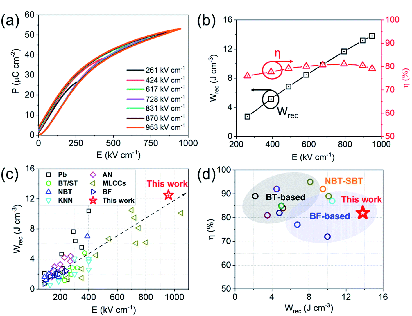 | ||
| Fig. 6 (a) Room temperature (RT) unipolar P–E loops and (b) calculated energy storage properties for BF–BT–0.13BLN multilayers. (c) Comparison of Wrecvs. electric field for different lead/lead-free bulk ceramics and multilayers.24–56,79–99 (d) Comparison of Wrecvs. η for lead-free multilayers.31,33–35,43,51,56,99,100 | ||
The unipolar P–E loops and energy storage properties (Wrec and η), obtained from 25 to 100 °C, from 0.01 to 100 Hz and cycled up to 104 times at 400 kV cm−1 are shown in Fig. 7. Wrec is temperature stable (<10%) from 25 to 100 °C, with little variation (<5%) as a function of frequency from 0.01 to 100 Hz and cyclic poling up to 104 times.
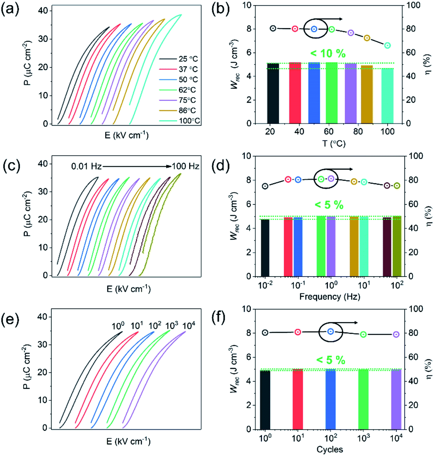 | ||
| Fig. 7 (a) Unipolar P–E loops at temperature range from 25 to 100 °C and (b) calculated energy storage properties at 400 kV cm−1; (c) unipolar P–E loops at frequency range from 0.01 to 100 Hz and (d) calculated energy storage properties at 400 kV cm−1; (e) unipolar P–E loops cycled up to 104 times and (f) calculated energy storage properties for BF–BT–0.13BLN multilayers at 400 kV cm−1. | ||
There are many factors which influence the excellent properties of these materials. The high value of Wrec is a direct consequence of being able to apply a large electric field without breakdown to a material whose crystal chemistry is designed to house highly polarisable ions within a matrix of dissimilar sized ABO3 perovskite unit cells (enhanced local polarisability).59 Temperature stability is still limited mainly by the conductivity mechanisms which become active under high electric field. In BF–BT based ceramics, VO diffusion is facilitated above 100 °C at high electric field and creates loss, widening the unipolar loop and reducing efficiency. Nonetheless, in comparison to polymer-based capacitors with similar energy densities, the materials show promise for high-temperature applications. Our multilayers exhibit negligible degradation after 104 cycles of the unipolar P–E loops, possibly due to the absence of significant strain (S < 0.03%) at 400 kV cm−1. Excellent fatigue properties are often associated with relaxor-like compositions, particular ones whose permittivity maximum is suppressed through doping with a third end member.32,33,51 The low strain prevents large cyclic changes in dimensions and eventual micro-cracking. Lead-based bulk ceramic or ceramic films, often exhibit excellent energy storage performance but are accompanied by high electric field-induced strain (S > 0.4%), leading to thermo- and mechanical-related failure due to micro-cracking.101–103
Multilayers with x = 0.13 therefore, have the potential to replace the lead-based systems for pulsed power applications. Furthermore, BT–BF–0.13BLN multilayers are rare-earth (RE)-free with low sintering temperature ∼890 °C, providing an opportunity for sustainable manufacturing and indicating potential compatibility with Ag – 10% Pd internal electrodes.
Conclusions
In summary, novel (0.7 − x)BiFeO3–0.30BaTiO3–xBi(Li0.5Nb0.5)O3 (BF–BT–xBLN) ceramics and multilayers are successfully fabricated using solid–state reaction and tape-casting, respectively. Wrec ∼13.8 J cm−3 was recorded ∼950 kV cm−1 for BF-BT-0.13BLN multilayers with ∼8 μm thick dielectric layers. Under electric field of 400 kV cm−1, multilayers are temperature stable (<10%) from RT to 100 °C, frequency independent (<5%) from 0.01 to 100 Hz and fatigue-resistant (<5%) up to 104 cycles of the unipolar P–E loops. Additionally, BT–BF–0.13BLN multilayers are RE-free with a low sintering temperature (890 °C) and are therefore considered promising lead-free candidates for energy storage applications.Materials and methods
Ceramics and MLCCs fabrication
BF–BT based ceramics within the ternary solid solution, (0.7 − x)BiFeO3–0.3BaTiO3–xBi(Li0.5Nb0.5)O3 (BF–BT–xBLN, x = 0.00, 0.02, 0.5, 0.08, 0.10, 0.13, 0.15) were synthesized using conventional solid–state reaction.51,52 Ceramic multilayers were fabricated using an MTI MSK-AFA-II tape caster with a single doctor blade on a single-side silicon-coated mylar film. Pt electrodes were printed onto the tape using a DEK 247 screen printer, followed by tape stacking and hot-pressing (70 °C for 10 min). Multilayers were sintered at 890 °C for 2 h with an intermediate binder burnout step (180 °C for 4 h and 300 °C for 2 h). Finally, Au terminal electrodes were painted on the side of the multilayers and fired 2 h at 850 °C.56Microstructural characterization
Densities of sintered ceramics were determined by the Archimedes method and achieved >95% of the theoretical density. The phase assemblage, structure and microstructure at RT were evaluated by XRD (Bruker D2 Phaser) and SEM (FEI Inspect F50) equipped with BSE and EDS detectors). For SEM, sintered samples were firstly ground then polished to a mirror finish using wet abrasive paper and diamond paste (MetPrep Ltd.). Specimens for TEM were prepared by mechanical grinding, polishing and then ion milling. Ion milling was performed using a Gatan precision ion polishing system (PIPS II) at liquid nitrogen temperature to minimize surface damage of the specimens. A JEOL-F200 microscope was used for HRTEM and STEM imaging as well as EDS analysis.Electrical characterization
For electrical measurements, Au was sputtered on the top and bottom surfaces of ceramic pellets. Ferroelectric P–E loops were measured using an aixACCT TF 2000E system from RT to 125 °C using a 1 Hz triangular signal. The dielectric properties as a function of temperature were evaluated from RT to 600 °C at 1, 10, 100 and 250 kHz using an LCR meter (Agilent 4184A). Impedance data were collected using an Agilent E4980A impedance AC analyser from RT to 400 °C at intervals of 25 °C. Impedance data was normalised by a geometric factor (thickness/surface area) and then analysed using a ZView software (Scribner Associates, Inc., Southern Pines, NC). Details of how resistance and capacitance values were extracted for the different electro-active regions from combined Z′′ and M′′ spectroscopic plots are given in previous publications.68,104,105Conflicts of interest
The authors declare no competing financial interest.Acknowledgements
This work was supported by the Engineering and Physical Sciences Research Council (EP/L017563/1 and EP/N010493/1), Henry Royce Institute for Advanced Materials, funded through EPSRC grants EP/R00661X/1, EP/S019367/1, EP/P02470X/1 and EP/P025285/1 and National Natural Science Foundation of China (51602060 and 51402005). The authors are grateful for support provided by Functional Materials and Devices group from University of Sheffield and would like to thank Zhongming Fan from Iowa State University for assistance with TEM work.References
- B. Chu, X. Zhou, K. Ren, B. Neese, M. Lin, Q. Wang, F. Bauer and Q. M. Zhang, Science, 2006, 313, 334–336 CrossRef CAS PubMed.
- Q. Li, L. Chen, M. R. Gadinski, S. Zhang, G. Zhang, H. Li, A. Haque, L. Chen, T. Jackson, Q. Wang and E. Iagodkine, Nature, 2015, 523, 576–579 CrossRef CAS PubMed.
- L. Zhao, Q. Liu, J. Gao, S. Zhang and J. F. Li, Adv. Mater., 2017, 29, 1701824–1701827 CrossRef PubMed.
- G. R. Love, J. Am. Ceram. Soc., 1990, 73, 323–328 CrossRef CAS.
- K. Seongtae, W. Hackenberger, E. Alberta, E. Furman and M. Lanagan, IEEE Electrical Insulation Magazine, 2011, 27, 43–55 Search PubMed.
- H. Sun, W. Wang, H. Jiao, S. Wang, H. Zhu and S. Jiao, Chem. Commun., 2015, 51, 11892–11895 RSC.
- X. Zhang, S. Jiao, J. Tu, W.-L. Song, X. Xiao, S. Li, M. Wang, H. Lei, D. Tian, H. Chen and D. Fang, Energy Environ. Sci., 2019, 12, 1918–1927 RSC.
- S. Wang, S. Jiao, J. Wang, H.-S. Chen, D. Tian, H. Lei and D.-N. Fang, ACS Nano, 2017, 11, 467–477 Search PubMed.
- Z. Yu, S. Jiao, S. Li, X. Chen, W.-L. Song, T. Teng, J. Tu, H.-S. Chen, G. Zhang and D.-N. Fang, Adv. Funct. Mater., 2019, 29, 1806799 CrossRef.
- Y. Song, S. Jiao, J. Tu, J. Wang, Y. Liu, H. Jiao, X. Mao, Z. Guo and D. J. Fray, J. Mater. Chem. A, 2017, 5, 1282–1291 RSC.
- H. Jiao, C. Wang, J. Wang, J. Tu, J. Zhu and S. Jiao, Chem. Commun., 2017, 53, 2331–2334 RSC.
- S. Wang, Z. Yu, J. Tu, J. Wang, D. Tian, Y. Liu and S. Jiao, Adv. Energy Mater., 2016, 6, 1600137 CrossRef.
- W. Wang, B. Jiang, W. Xiong, H. Sun, Z. Lin, L. Hu, J. Tu, J. Hou, H. Zhu and S. Jiao, Sci. Rep., 2013, 3, 3383 CrossRef PubMed.
- W. B. Hu, Y. Liu, R. L. Withers, T. J. Frankcombe, L. Noren, A. Snashall, M. Kitchin, P. Smith, B. Gong, H. Chen, J. Schiemer, F. Brink and J. Wong-Leung, Nat. Mater., 2013, 12, 821–826 CrossRef CAS PubMed.
- Q. Li, G. Zhang, F. Liu, K. Han, M. R. Gadinski, C. Xiong and Q. Wang, Energy Environ. Sci., 2015, 8, 922–931 RSC.
- C. Liu, F. Li, L. P. Ma and H. M. Cheng, Adv. Mater., 2010, 22, E28–E62 CrossRef CAS PubMed.
- I. Hadjipaschalis, A. Poullikkas and V. Efthimiou, Renewable Sustainable Energy Rev., 2009, 13, 1513–1522 CrossRef.
- H. Chen, T. N. Cong, W. Yang, C. Tan, Y. Li and Y. Ding, Prog. Nat. Sci., 2009, 19, 291–312 CrossRef CAS.
- Z. Fan, C. Zhou, X. Ren and X. Tan, Appl. Phys. Lett., 2017, 111, 252902 CrossRef.
- Z. Fan, J. Koruza, J. Rodel and X. Tan, Acta Mater., 2018, 151, 253–259 CrossRef CAS.
- Z. Fan and X. Tan, J. Eur. Ceram. Soc., 2018, 38, 3472–3477 CrossRef CAS.
- Z. Fan, L. Zhou, T. H. Kim, J. Zhang, S. T. Zhang and X. Tan, Phys. Rev. Mater., 2019, 3, 024402 CrossRef CAS.
- H. Wang, Y. Liu, T. Yang and S. Zhang, Adv. Funct. Mater., 2019, 29, 1807321 CrossRef.
- L. Zhao, Q. Liu, S. Zhang and J.-F. Li, J. Mater. Chem. A, 2016, 4, 8380 CAS.
- Y. Tian, L. Jin, H. Zhang, Z. Xu, X. Wei, E. D. Politova, S. Y. Stefanovich, N. V. Tarakina, I. Abrahams and H. Yan, J. Mater. Chem. A, 2016, 4, 17279 RSC.
- L. Zhao, J. Gao, Q. Liu, S. Zhang and J.-F. Li, ACS Appl. Mater. Interfaces, 2018, 10, 819–826 CrossRef CAS PubMed.
- L. Zhao, Q. Liu, J. Gao, S. Zhang and J.-F. Li, Adv. Mater., 2017, 29, 1701824 CrossRef PubMed.
- Y. Tian, L. Jin, H. Zhang, Z. Xu, X. Wei, G. Viola, I. Abrahams and H. Yan, J. Mater. Chem. A, 2017, 5, 17525 RSC.
- Q. Yuan, G. Li, F.-Z. Yao, S.-D. Cheng, Y. Wang, R. Ma, S.-B. Mi, M. Gu, K. Wang, J.-F. Li and H. Wang, Nano Energy, 2018, 52, 203–210 CrossRef CAS.
- Q. Fan, M. Liu, C. Ma, L. Wang, S. Ren, L. Lu, X. Lou and C.-L. Jia, Nano Energy, 2018, 51, 539–545 CrossRef CAS.
- W.-B. Li, D. Zhou, R. Xu, L.-X. Pang and I. M. Reaney, ACS Appl. Energy Mater., 2018, 1, 5016–5023 CrossRef CAS.
- W.-B. Li, D. Zhou, L.-X. Pang, R. Xu and H.-H. Guo, J. Mater. Chem. A, 2017, 5, 19607–19612 RSC.
- W. Li, D. Zhou, R. Xu, D.-W. Wang, J. Su, L.-X. Pang, W. Liu and G.-H. Chen, ACS Appl. Energy Mater., 2019, 2, 5499–5506 CrossRef CAS.
- Z. Cai, C. Zhu, H. Wang, P. Zhao, L. Chen, L. Li and X. Wang, J. Mater. Chem. A, 2019, 7, 14575 RSC.
- P. Zhao, H. Wang, L. Wu, L. Chen, Z. Cai, L. Li and X. Wang, Adv. Energy Mater., 2019, 9, 1803048 CrossRef.
- Z. Shen, X. Wang, B. Luo and L. Li, J. Mater. Chem. A, 2015, 3, 18146 RSC.
- H. Qi and R. Zuo, J. Mater. Chem. A, 2019, 7, 3971 RSC.
- Y. Pu, L. Zhang, Y. Cui and M. Chen, ACS Sustainable Chem. Eng., 2018, 6, 6102–6109 CrossRef CAS.
- J. Wu, A. Mahajan, L. Riekehr, H. Zhang, B. Yang, N. Meng, Z. Zhang and H. Yan, Nano Energy, 2018, 50, 723–732 CrossRef CAS.
- H. Yang, F. Yan, Y. Lin and T. Wang, ACS Sustainable Chem. Eng., 2017, 5, 10215–10222 CrossRef CAS.
- Z. Pan, D. Hu, Y. Zhang, J. Liu, B. Shen and J. Zhai, J. Mater. Chem. C, 2019, 7, 4072–4078 RSC.
- C. Yang, P. Lv, J. Qian, Y. Han, J. Ouyang, X. Lin, S. Huang and Z. Cheng, Adv. Energy Mater., 2019, 9, 1803949 CrossRef.
- J. Li, F. Li, Z. Xu and S. Zhang, Adv. Mater., 2018, 30, 1802155 CrossRef PubMed.
- Y. Zhang, W. Li, S. Xu, Z. Wang, Y. Zhao, J. Li and W. Fei, J. Mater. Chem. A, 2018, 6, 24550–24559 RSC.
- F. Li, J. Zhai, B. Shen, X. Liu and H. Zeng, Mater. Res. Lett., 2018, 6, 345–352 CrossRef CAS.
- B. Qu, H. Du, Z. Yang, Q. Liu and T. Liu, RSC Adv., 2016, 6, 34381 RSC.
- Z. Yang, H. Du, S. Qu, Y. Hou, H. Ma, J. Wang, J. Wang, X. Wei and Z. Xu, J. Mater. Chem. A, 2016, 4, 13778 RSC.
- T. Shao, H. Du, H. Ma, S. Qu, J. Wang, J. Wang, X. Wei and Z. Xu, J. Mater. Chem. A, 2017, 5, 554 RSC.
- B. Qu, H. Du, Z. Yang and Q. Liu, J. Am. Ceram. Soc., 2017, 100, 1517–1526 CrossRef CAS.
- D. Wang, Z. Fan, W. Li, D. Zhou, A. Feteira, G. Wang, S. Murakami, S. Sun, Q. Zhao, X. Tan and I. M. Reaney, ACS Appl. Energy Mater., 2018, 1, 4403–4412 CrossRef CAS.
- D. Wang, Z. Fan, D. Zhou, A. Khesro, S. Murakami, A. Feteira, Q. Zhao, X. Tan and I. M. Reaney, J. Mater. Chem. A, 2018, 6, 4133 RSC.
- D. Zheng, R. Zuo, D. Zhang and Y. Li, J. Am. Ceram. Soc., 2015, 98, 2692–2695 CrossRef CAS.
- D. Zheng and R. Zuo, J. Eur. Ceram. Soc., 2017, 37, 413–418 CrossRef CAS.
- N. Liu, R. Liang, X. Zhao, C. Xu, Z. Zhou and X. Dong, J. Am. Ceram. Soc., 2018, 101, 3259–3265 CrossRef CAS.
- D. Wang, G. Wang, S. Murakami, Z. Fan, A. Feteira, D. Zhou, S. Sun, Q. Zhao and I. M. Reaney, J. Adv. Dielectr., 2018, 8, 1830004 CrossRef CAS.
- G. Wang, J. Li, X. Zhang, Z. Fan, F. Yang, A. Feteira, D. Zhou, D. C. Sinclair, T. Ma, X. Tan, D. Wang and I. M. Reaney, Energy Environ. Sci., 2019, 12, 582 RSC.
- M. H. Lee, D. J. Kim, J. S. Park, S. W. Kim, T. K Song, M.-H. Kim, W.-J. Kim, D. Do and I.-K. Jeong, Adv. Mater., 2015, 27, 6976 CrossRef CAS PubMed.
- G. H. Ryu, A. Hussain, M. H. Lee, R. A. Malik, T.-K. Song, W.-J. Kim and M.-H. Kim, J. Eur. Ceram. Soc., 2018, 38, 4414–4421 CrossRef CAS.
- I. Lewin, W. J. Laws, D. Wang and I. M. Reaney, Appl. Phys. Lett., 2017, 111, 212902 CrossRef.
- P. Fiorenza, R. L. Nigro, P. Delugas, V. Raineri, A. G. Mould and D. C. Sinclair, Appl. Phys. Lett., 2009, 95, 142904 CrossRef.
- J. P. Heath, J. H. Harding, D. C. Sinclair and J. S. Dean, Adv. Funct. Mater., 2019, 29, 1904036 CrossRef.
- J. T. S. Irvine, D. C. Sinclair and A. R. West, Adv. Mater., 1990, 2, 132–138 CrossRef CAS.
- L. Yang, X. Kong, F. Li, H. Hao, Z. Cheng, H. Liu, J.-F. Li and S. Zhang, Prog. Mater. Sci., 2019, 102, 72–108 CrossRef CAS.
- R. Gerson and T. C. Marshall, J. Appl. Phys., 1959, 30, 1650 CrossRef CAS.
- H. Pan, F. Li, Y. Liu, Q. Zhang, M. Wang, S. Lan, Y. Zheng, J. Ma, L. Gu, Y. Shen, P. Yu, S. Zhang, L.-Q. Chen, Y.-H. Lin and C.-W. Nan, Science, 2019, 365, 578–582 CrossRef CAS PubMed.
- F. Yang, M. Li, L. Li, P. Wu, E. Pradal-Velazquez and D. C. Sinclair, J. Mater. Chem. A, 2018, 6, 5243–5254 RSC.
- M. Li, L. Li, J. Zang and D. C. Sinclair, Appl. Phys. Lett., 2015, 106, 102904 CrossRef.
- L. Li, M. Li, H. Zhang, I. M. Reaney and D. C. Sinclair, J. Mater. Chem. C, 2016, 4, 5779–5786 RSC.
- A. Khesro, D. Wang, F. Hussain, D. C. Sinclair, A. Feteira and I. M. Reaney, Appl. Phys. Lett., 2016, 109, 142907 CrossRef.
- S. Murakami, D. Wang, A. Mostaed, A. Khesro, A. Feteira, D. C. Sinclair, Z. Fan, X. Tan and I. M. Reaney, J. Am. Ceram. Soc., 2018, 101, 5428–5442 CrossRef CAS.
- S. Murakami, N. T. A. F. Ahmed, D. Wang, A. Feteira, D. C. Sinclair and I. M. Reaney, J. Eur. Ceram. Soc., 2018, 38, 4220–4231 CrossRef CAS.
- R. D. Shannon, Acta Crystallogr., Sect. A: Cryst. Phys., Diffr., Theor. Gen. Crystallogr., 1976, 32, 751 CrossRef.
- G. Wang, Z. Fan, S. Murakami, Z. Lu, D. A. Hall, D. C. Sinclair, A. Feteira, X. Tan, J. L. Jones, A. K. Kleppe, D. Wang and I. M. Reaney, J. Mater. Chem. A, 2019, 7, 21254–21263 RSC.
- I. Calisir, A. K. Kleppe, A. Feteira and D. A. Hall, J. Mater. Chem. C, 2019, 7, 10218–10230 RSC.
- I. Calisir, A. A. Amirov, A. K. Kleppe and D. A. Hall, J. Mater. Chem. A, 2018, 6, 5378–5397 RSC.
- I. Calisir and D. A. Hall, J. Mater. Chem. C, 2018, 6, 134–146 RSC.
- Y. Lin, D. Li, M. Zhang, S. Zhan, Y. Yang, H. Yang and Q. Yuan, ACS Appl. Mater. Interfaces, 2019, 11, 36824–36830 CrossRef CAS PubMed.
- G. Wang, Z. Lu, Z. Zhang, A. Feteira, C. C. Tang and D. A. Hall, J. Am. Ceram. Soc., 2019, 102, 7746–7754 CrossRef CAS.
- L. Zhang, S. Jiang, B. Fan and G. Zhang, J. Alloys Compd., 2015, 622, 162–165 CrossRef CAS.
- Z. Liu, X. Chen, W. Peng, C. Xu, X. Dong, F. Cao and G. Wang, Appl. Phys. Lett., 2015, 106, 262901 CrossRef.
- Q. Zhang, H. Tong, J. Chen, Y. Lu, T. Yang, X. Yao and Y. He, Appl. Phys. Lett., 2016, 109, 262901 CrossRef.
- R. Xu, B. Li, J. Tian, Z. Xu, Y. Feng, X. Wei, D. Huang and L. Yang, Appl. Phys. Lett., 2017, 110, 142904 CrossRef.
- Q. Zhang, J. Chen, Y. Lu, T. Yang, X. Yao and Y. He, J. Am. Ceram. Soc., 2016, 99, 3853–3856 CrossRef CAS.
- Q. Zhao, H. Lei, G. He, J. Di, D. Wang, P. Tan, H. Jin and H. M. Cao, Ceram. Int., 2016, 42, 1314–1317 CrossRef CAS.
- F. Yan, H. Yang, Y. Lin and T. Wang, Inorg. Chem., 2017, 56, 13510–13516 CrossRef CAS PubMed.
- J. Yin, X. Lv and J. Wu, Ceram. Int., 2017, 43, 13541–13546 CrossRef CAS.
- Y. Pu, M. Yao, L. Zhang and M. Chen, J. Alloys Compd., 2017, 702, 171–177 CrossRef CAS.
- H. Tao and J. Wu, J. Mater. Sci.: Mater. Electron., 2017, 28, 16199–16204 CrossRef CAS.
- H. Yang, F. Yan, Y. Lin, T. Wang, L. He and F. Wang, J. Alloys Compd., 2017, 710, 436–445 CrossRef CAS.
- H. Yang, F. Yan, Y. Lin, T. Wang, F. Wang, Y. Wang, L. Guo, W. Tai and H. Wei, J. Eur. Ceram. Soc., 2017, 37, 3303–3311 CrossRef CAS.
- H. Yang, F. Yan, Y. Lin and T. Wang, Appl. Phys. Lett., 2017, 111, 253903 CrossRef.
- Q. M. Zhang, L. Wang, J. Luo, Q. Tang and J. Du, Int. J. Appl. Ceram. Technol., 2010, 7, E124–E128 CrossRef.
- Y. H. Huang, Y. J. Wu, W. J. Qiu, J. Li and X. M. Chen, J. Eur. Ceram. Soc., 2015, 35, 1469–1476 CrossRef CAS.
- W. B. Li, D. Zhou and L.-X. Pang, Appl. Phys. Lett., 2017, 110, 132902–132905 CrossRef.
- T. Wang, L. Jin, C. C. Li, Q. Y. Hu and X. Y. Wei, J. Am. Ceram. Soc., 2015, 98, 559–566 CrossRef CAS.
- Q. Y. Hu, L. Jin, T. Wang, C. C. Li, Z. Xing and X. Y. Wei, J. Alloys Compd., 2015, 640, 416–420 CrossRef CAS.
- Q. Xu, J. Xie, Z. C. He, L. Zhang, M. H. Cao, X. D. Huang, M. T. Lanagan, H. Hao, Z. H. Yao and H. X. Liu, J. Eur. Ceram. Soc., 2017, 37, 99–106 CrossRef CAS.
- L. Chen, Y. Li, Q. Zhang and X. Hao, Ceram. Int., 2016, 42, 12537–12542 CrossRef CAS.
- H. Ogihara, C. A. Randall and S. Trolier-McKinstry, J. Am. Ceram. Soc., 2009, 92, 1719–1724 CrossRef CAS.
- G. Wang, Z. Lu, J. Li, H. Ji, H. Yang, L. Li, S. Sun, A. Feteira, H. Yang, R. Zuo, D. Wang and I. M. Reaney, J. Eur. Ceram. Soc., 2020, 40, 1779–1783 CrossRef CAS.
- Q. Zhang, J. Chen, Y. Lu, T. Yang, X. Yao and Y. He, J. Am. Ceram. Soc., 2016, 99, 3853–3856 CrossRef CAS.
- L. Chen, N. Sun, Y. Li, Q. Zhang, L. Zhang and X. Hao, J. Am. Ceram. Soc., 2018, 101, 2313–2320 CrossRef CAS.
- M. S. Mirshekarloo, K. Yao and T. Sritharan, Appl. Phys. Lett., 2010, 97, 142902 CrossRef.
- L. Li, M. Li, I. M. Reaney and D. C. Sinclair, J. Mater. Chem. C, 2017, 5, 6300–6310 RSC.
- L. Li, M. Li and D. C. Sinclair, Appl. Phys. Lett., 2018, 112, 182907 CrossRef.
Footnotes |
| † Electronic supplementary information (ESI) available. See DOI: 10.1039/d0ta00216j |
| ‡ G. W., Z. L. H. Y. and H. J. contributed equally to this work and should be considered as co-first authors. |
| This journal is © The Royal Society of Chemistry 2020 |