
 Open Access Article
 This Open Access Article is licensed under a Creative Commons Attribution-Non Commercial 3.0 Unported Licence
Evolution of pure hydrocarbon hosts: simpler structure, higher performance and universal application in RGB phosphorescent organic light-emitting diodes†
Qiang
Wang‡
 a,
Fabien
Lucas
b,
Cassandre
Quinton
b,
Yang-Kun
Qu
a,
Joëlle
Rault-Berthelot
b,
Olivier
Jeannin
b,
Sheng-Yi
Yang
a,
Fan-Cheng
Kong
a,
Sarvendra
Kumar
a,
Liang-Sheng
Liao
a,
Cyril
Poriel
*b and
Zuo-Quan
Jiang
*a
a,
Fabien
Lucas
b,
Cassandre
Quinton
b,
Yang-Kun
Qu
a,
Joëlle
Rault-Berthelot
b,
Olivier
Jeannin
b,
Sheng-Yi
Yang
a,
Fan-Cheng
Kong
a,
Sarvendra
Kumar
a,
Liang-Sheng
Liao
a,
Cyril
Poriel
*b and
Zuo-Quan
Jiang
*a
aInstitute of Functional Nano & Soft Materials (FUNSOM), Jiangsu Key Laboratory for Carbon-Based Functional Materials & Devices, Soochow University, Suzhou, Jiangsu 215123, China. E-mail: zqjiang@suda.edu.cn
bUniv. Rennes, CNRS, ISCR-UMR 6226, F-35000 Rennes, France. E-mail: Cyril.poriel@univ-rennes1.fr
First published on 5th May 2020
Abstract
In the field of phosphorescent organic light-emitting diodes (PhOLEDs), designing high-efficiency universal host materials for red, green and blue (RGB) phosphors has been quite a challenge. To date, most of the high-efficiency universal hosts reported incorporate heteroatoms, which have a crucial role in the device performance. However, the introduction of different kinds of heterocycles increases the design complexity and cost of the target material and also creates potential instability in the device performance. In this work, we show that pure aromatic hydrocarbon hosts designed with the 9,9′-spirobifluorene scaffold are high-efficiency and versatile hosts for PhOLEDs. With external quantum efficiencies of 27.3%, 26.0% and 27.1% for RGB PhOLEDs respectively, this work not only reports the first examples of high-efficiency pure hydrocarbon materials used as hosts in RGB PhOLEDs but also the highest performance reported to date for a universal host (including heteroatom-based hosts). This work shows that the PHC design strategy is promising for the future development of the OLED industry as a high-performance and low-cost option.
Introduction
Currently, the host–guest system is mostly used to construct an emitting-layer (EML) in an electroluminescent device for high efficiency. In a phosphorescent OLED (PhOLED), the EML commonly contains a transition metal complex triplet emitter dispersed in an organic host matrix. The 100% internal quantum efficiency is fulfilled through harvesting both the singlet (25%) and triplet (75%) excitons.1 During the past two decades, intense research has been focused on developing high-efficiency hosts. The most popular ones are the bipolar hosts constructed by the incorporation of suitable electron-rich (such as carbazole,2–5N-phenylacridine,6 diphenylamine7 and triphenylamine7–9) and electron-poor (such as pyridine,10 oxadiazole,11 dioxothioxanthene,12,13 and imidazole14–16) heterocycles. The best among them achieved over 25% external quantum efficiency (EQE) in PhOLEDs,5,9,10,13,14 while some of them exhibited moderately low performance.2,4,6–8,15,16 Their complicated structure, however, increases synthetic complexity and production cost. In addition, it is also recognized that OLED instability, which is one of the main problems to be addressed at the current stage of development, is partially caused by the fragile C–N, C–P and C–S bonds of such heteroatom based hosts.17–19 The chemical stabilities of various useful molecular fragments (such as aryl sulfone and aryl phosphine oxide) in their first triplet states (ET) have thus been recently investigated.20Another approach to design host materials without any heterocycles, the so-called pure hydrocarbons (PHCs), was proposed in 2005, but it has attracted little attention because of the poor device performance.21 For instance, the first PHC host was a 9,9′-spirobifluorene (SBF) trimer linked via the para site which achieved 10% EQE in red PhOLEDs.21 The SBF unit was then extended to a dihydroindenofluorene skeleton and used as a host for green phosphors in a PhOLED, displaying nevertheless a low EQE of 14%.22 These studies have paved the way for the further design of PHC host materials and other examples were be reported afterwards.23–25 The performance of PHC based PhOLEDs, however, has remained low until 2015 when we proposed that the meta-linkage was critical for constructing the new generation of PHC hosts.26 In 2019, a series of dimers derived from the C3 or C1 site of SBF achieved a high EQE up to 23% in blue PhOLEDs.27 Even so, this encouraging progress is still incomparable with the best heteroatom hosts for blue, green, and red PhOLEDs.
In this work, we report a series of novel PHC materials, featuring further simplified structures from SBF dimers 27 to mono SBF derivatives (Fig. 1). These molecules are constructed on a SBF scaffold substituted at C3/C6 positions thanks to an efficient one-step synthesis. These positions form a meta linkage with the constituted bridged biphenyl (i.e. fluorene), leading in principle to an electronic decoupling between the two fragments.27,28 Given that the substituent itself also has a crucial role in the device performance, two different side groups were investigated, phenyl and meta-terphenyl. As shown in Fig. 1, mSPh and mSPh2 possess one or two simple phenyl rings respectively, and mSTPh and mSTPh2 incorporate one or two bulkier meta-terphenyl fragments, respectively. The monosubstituted non-symmetric host, mSTPh, achieves a high first singlet–triplet state energy (ES/ET) of 3.60/2.82 eV and exhibits over 26% EQE in Red (R), Green (G) and Blue (B) PhOLEDs. After comprehensively comparing with previously reported universal hosts fitted for RGB emitting devices, this PHC host displays the highest overall performance reported to date (including heteroatom-based hosts, Table S16†). This work shows that the PHC design strategy is promising for the future development of the OLED industry as a high-performance and low-cost option.
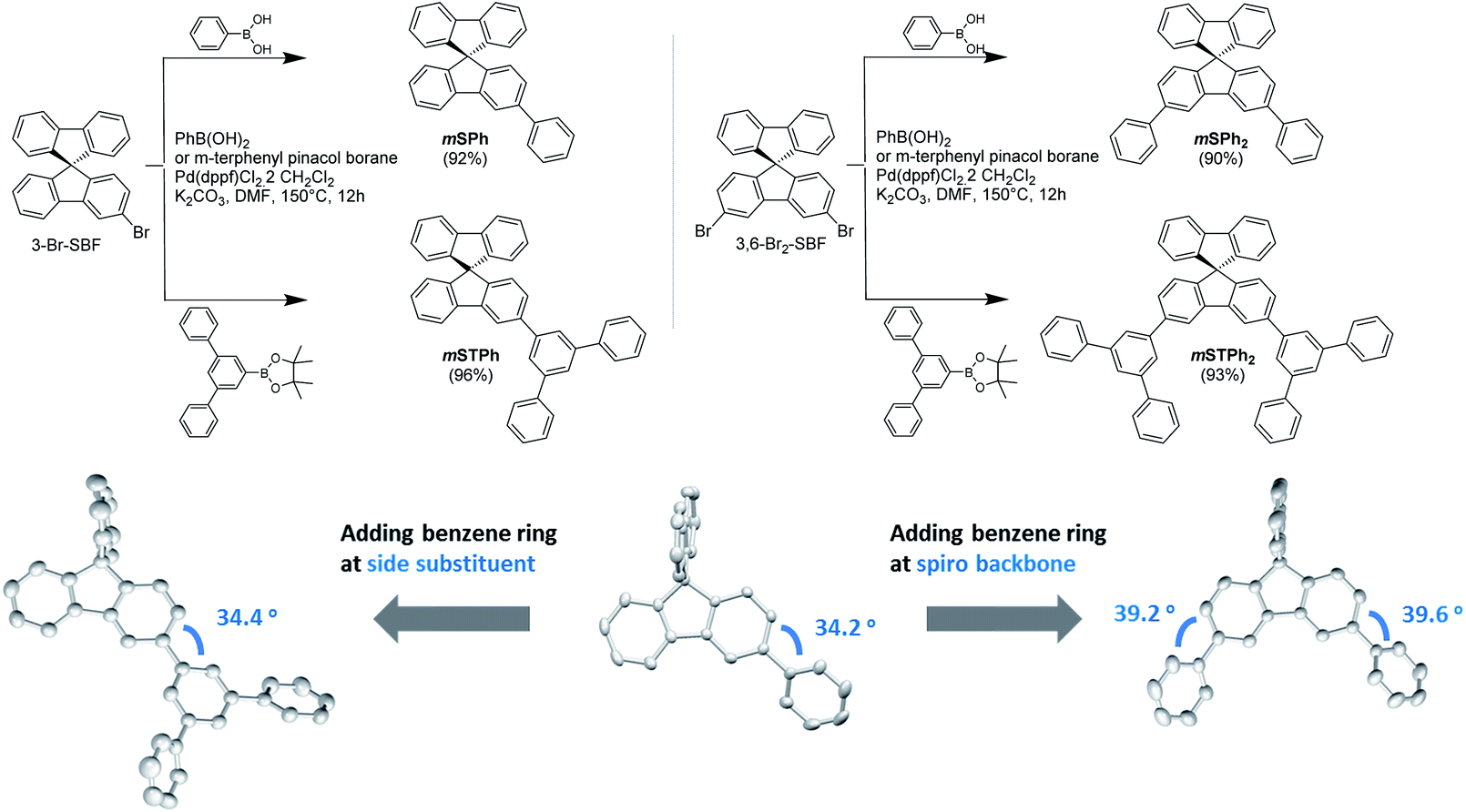 | ||
| Fig. 1 Synthesis of the PHC host materials (Top) and the dihedral angle variation when adding a benzene ring (Bottom). | ||
Results and discussion
Synthesis and characterization
The chemical structures of the materials are shown in Fig. 1. For further industrial application, the synthetic approach of the host materials is of great importance. This approach should be short, high yielding and low cost. The present hosts have been easily synthesized at the gram scale through a one-step approach from commercial precursors 3-Br-SBF and 3,6-Br2-SBF (Fig. 1 and ESI†). The pendant substituents, phenyl or terphenyl, are efficiently attached to the SBF backbone via classical Pd-catalysed coupling (Fig. 1, Top) with yields over 90%.The most important parameter in the understanding of the electronic properties of these molecules is the dihedral angle between the substituent and the fluorene.28 This angle drives, in part, the electronic coupling between the two fragments and hence the electrochemical and photophysical properties (see below). The different ways of extending the SBF core with benzene rings (on the substituent side group or directly on the fluorene core) have different structural impacts as shown in the crystal structures (Fig. 1, Bottom): (i) a slight increase in the dihedral angle going from mono to disubstituted compounds (ca. 34 vs. 39°) and (ii) no influence of the substituent itself (phenyl vs. terphenyl). These features show that there is no steric hindrance between the fluorene and the substituent and that the electronic properties (discussed below) are not driven by steric parameters, which is a drastically different behavior from that observed for the SBF dimers, recently reported.27
As shown in Fig. 2a, all the hosts displayed similar UV-vis absorption profiles, with thin and high intensity bands at 310–311 nm in dilute toluene solutions (10−5 M) as commonly observed in SBF based compounds.28,29 In addition to this band, the four compounds display a red-shifted band at either 317 nm (low molar absorption coefficient, ε, and low oscillator strength, see natural transition orbitals calculations in the ESI†) for the two monosubstituted SBFs, mSPh and mSTPh, or at 324/325 nm (high ε and high oscillator strength, ESI†) for the two disubstituted ones, mSPh2 and mSTPh2. This reveals an electronic coupling between the fluorene backbone and one or two phenyl/terphenyl substituents, which is indicated in the density of the pendant phenyl units in hole and electron states (Fig. S12–15, ESI†). This extension of the π-conjugation, despite the meta positions being involved, has been previously observed for other meta linked SBF based materials26,28 and has been assigned to the presence of the spiro bridge at the para position of the substituent. It should be nevertheless mentioned that the exact origin of this feature has not been fully understood yet. Based on the onset of the absorption spectra, the optical band gaps (Eg) of mSPh, mSPh2, mSTPh and mSTPh2 were estimated to be 3.76, 3.70, 3.78 and 3.69 eV, respectively. It is shown that the four spectra remain in the near UV region, which is an important point for their use as hosts in PhOLEDs. The phosphorescence emission spectra, recorded at 77 K in toluene (Fig. 2c), provide the corresponding ET1 of mSPh, mSPh2, mSTPh and mSTPh2, estimated to be 2.82, 2.79, 2.82 and 2.79 eV, respectively (Table 1). The high ET1 of the four compounds results from the efficient confinement of triplet excitons on one fluorene (Fig. 2d; ET1 of SBF is measured to be 2.86 eV in toluene, Fig. S2, ESI†). These data clearly show that the nature of the substituent (phenyl vs. terphenyl) does not influence ET1 whereas the substitution pattern (mono vs. di) has a slight influence. However, as the nature and number of substituents have a non-negligible influence on the other properties (thermal and mobility of charge carriers, see below), this design strategy allows to maintain a high ET1, modifying, in the meantime, other properties. It should be noted that the ET1 trend is perfectly followed using theoretical calculations which provide values of 2.64 eV for the two monosubstituted compounds and 2.61 eV for the two disubstituted compounds, with an identical difference of 0.03 eV between theory and experiment (Table 1).
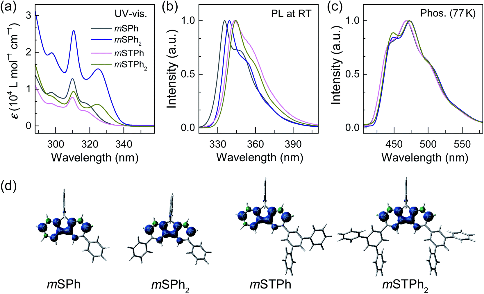 | ||
| Fig. 2 (a) UV-vis absorption spectra, (b) emission spectra at 298 K and (c) emission spectra at 77 K spectra in toluene of mSPh, mSPh2, mSTPh and mSTPh2. (d) triplet spin density distribution (TD-DFT, b3lyp/6-311+g(d,p), isovalue 0.004) of the molecules. | ||
| mSPh | mSPh2 | mSTPh | mSTPh2 | SBF 24,28 | mTPh | ||
|---|---|---|---|---|---|---|---|
| a In toluene, where λAbs is the absorption peak and λEM is the photoluminescence peak at room temperature. b Calculated from the first peak of emission at rt. c Calculated from the first phosphorescence peak (between brackets in nm) at 77 K in toluene. d From TD-DFT calculations (b3lyp/6-311+g(d,p)). e Calculated from the onset of the absorption spectra. f Calculated from the HOMO (CH2Cl2) − LUMO (DMF). g From CVs (CH2Cl2 in oxidation and DMF in reduction, Eonset is provided between brackets (V/SCE)). h Hole mobility (μh). i Electron mobility (μe). j In cyclohexane. k From ref. 23. | |||||||
| λ Abs (ε)a [nm] (104 L mol−1 cm−1) | 310 (1.32) | 311 (2.61) | 310 (0.79) | 310 (0.94) | 297 (0.72) | 246j,k | |
| 317 (0.63) | 325 (1.56) | 317 (0.41) | 324 (0.59) | 308 (1.45) | |||
| λ EM [nm] | 335/348 | 339/352 | 344/356 | 345/358 | 310/323 | 326/340 | |
| E S1 [eV] | 3.70 | 3.66 | 3.60 | 3.59 | 4.00 | 3.80 | |
| E T1 [eV] (nm) | Opt.c | 2.82 (440) | 2.79 (444) | 2.82 (440) | 2.79 (444) | 2.86 (433) | 2.89 (429) |
| Calc.d | 2.64 | 2.61 | 2.64 | 2.61 | — | — | |
| E g [eV] | Opt.e | 3.76 | 3.70 | 3.78 | 3.69 | 3.97 | 4.43j,k |
| Elec.f | 4.17 | 3.95 | 3.95 | 3.91 | 4.21 | 4.14k | |
| LUMO [eV] | Elec.g | −1.77 (−2.63) | −1.94 (−2.46) | −2.01 (−2.39) | −2.08 (−2.32) | −1.74 (−2.66) | −1.90 (−2.50) |
| Calc.d | −1.31 | −1.37 | −1.37 | −1.44 | — | — | |
| HOMO [eV] | Elec.g | −5.94 (1.54) | −5.89 (1.49) | −5.96 (1.56) | −5.99 (1.59) | −5.95 (1.55) | −6.04 (1.64) |
| Calc.d | −5.93 | −5.89 | −5.94 | −5.90 | — | — | |
| Thermal [°C] | T g | 90 | 126 | 133 | 176 | — | — |
| T d | 262 | 287 | 318 | 407 | 234 | 151 | |
| Mobility [cm2 V−1 s−1] | μ h (10−8)h | 3.12 | 2.25 | 2.64 | 3.08 | — | — |
| μ e (10−8)i | 0.15 | 0.49 | 3.55 | 8.59 | — | — | |
Thus, in the above events, it is interesting to observe that the Eg and ET1 were more dependent on the SBF substitution pattern than on the nature of substituents, with the peripheral phenyl rings of both mSTPh and mSTPh2 having little influence on these parameters. However, these peripheral rings influence the vibrational relaxation of molecules in their excited states as can be seen in the fluorescence spectra. As a result, the emission bands in toluene are red-shifted compared to those of SBF with the main peaks at 335/348, 339/352, 344/356 and 345/358 nm for mSPh, mSPh2, mSTPh and mSTPh2 respectively (Fig. 2b), while the most red-shifted being the two terphenyl substituted compounds.
The electrochemical properties were analyzed by cyclic voltammetry (CV) in CH2Cl2 (oxidation) and DMF (reduction) and compared with those of constituent units: SBF and m-terphenyl mTPh (Fig. 3a and b and ESI†). As shown in Fig. 3a-Right, mSPh is oxidized at a similar potential to that of its constituent building block SBF (Eoxonset = 1.54 and 1.55 V/SCE respectively) whereas mSPh2 is oxidized at a slightly lower potential (Eoxonset = 1.49 V). As listed in Table 1, the highest occupied molecular orbital (HOMO) levels calculated from the onset oxidation potentials are lying at ca. −5.94 eV for mSPh and at −5.89 eV for mSPh2 (compared to −5.95 eV for SBF). This suggests that the HOMO levels almost remain unaffected by the monosubstitution at C3 but affected by the disubstitution at C3/C6. Despite being weak (the contribution of the phenyl rings is indeed limited in the HOMO, Fig. 3c), the electronic coupling between the fluorene and the substituents at meta positions observed in the UV-vis absorption spectra is confirmed. On reduction, mSPh and mSPh2 display two successive reduction waves (Fig. 3a-Left) providing a lowest unoccupied molecular orbital (LUMO) level lying at −1.77 eV for mSPh and −1.94 eV for mSPh2 (compared to −1.74 eV for SBF). Thus, due to the double substitution, the LUMO of mSPh2 becomes deeper than that of mSPh in accordance with the trend detailed above for the HOMO. However, one can note that the LUMO energy level of mSPh2 is more affected by the double substitution than its HOMO energy level in accordance with the more pronounced contribution of the phenyl ring in the LUMO than in the HOMO (Fig. 3c). The resulting electrochemical Eg (HOMO (CH2Cl2) − LUMO (DMF)), therefore, appears more contracted for mSPh2 (3.95 eV) than for mSPh (4.17 eV) and for SBF (4.21 eV).
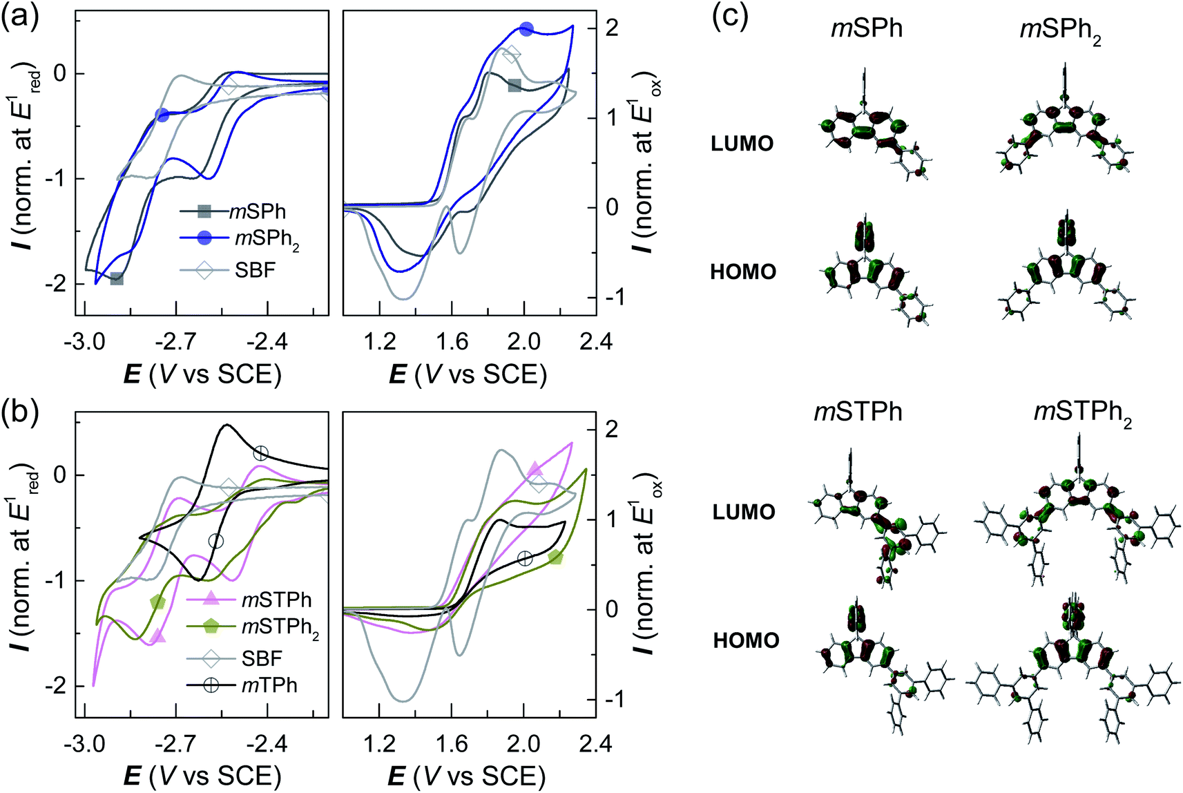 | ||
| Fig. 3 The cyclic voltammetry (CV) data of (a) mSPh and mSPh2 compared to those of SBF, and (b) mSTPh and mSTPh2 compared to those of mTPh and SBF (in reduction: DMF/[NBu4][PF6] 0.1 M; in oxidation: CH2Cl2/[Bu4NPF6] 0.2 M, sweep rate of 100 mV−1, platinum disk working electrode). (c) Frontier molecular orbitals (Top: LUMO, Bottom: HOMO, b3lyp/6-311+g(d,p), isovalue of 0.04). | ||
The terphenyl derivatives mSTPh and mSTPh2 display a very different behaviour. Indeed, the oxidation of mSTPh and mSTPh2 surprisingly appears to be more difficult than that of SBF (Eoxonset = 1.56, 1.59 and 1.55 V/SCE, respectively) clearly indicating an electron-withdrawing effect of the m-terphenyl substituent(s) on the SBF core in both mSTPh and mSTPh2 (Fig. 3c). Thus, the electron-withdrawing effect of the m-terphenyl substituent(s) is predominant compared to the extension of the π-conjugation and the resulting HOMO energies decrease therefore as follows: −5.95, −5.96, −5.99, and −6.04 eV for SBF, mSTPh, mSTPh2, and mTPh, respectively. In DMF, the two compounds are reduced in two successive reduction waves (Fig. 3b-Left), with the first maxima at −2.51 and −2.60 V for mSTPh and mSTPh2 respectively, showing an easier reduction process than mTPh (−2.63 V) and SBF (−2.79 V). This is in accordance with the electron-withdrawing effect of the terphenyl branch units. The LUMO levels are therefore estimated at −2.01 and −2.08 eV for mSTPh and mSTPh2 respectively, lower than those of mTPh (−1.90 eV) and SBF (−1.74 eV). This can be correlated with the electronic distribution observed in the LUMO of mSTPh and mSTPh2. Indeed, for both compounds, there is a strong implication of the terphenyl units in the LUMO, which is a different behaviour compared to that observed for the HOMO, almost entirely spreads out on the SBF core. This concludes that simple phenyl and terphenyl units have different influences on the HOMO/LUMO energy levels of these investigated compounds, but both maintain a high ET1, a key feature for the present application. From these studies, one can observe that the electrochemical Eg is more contracted for mSTPh2 (3.91 eV) than for mSTPh (3.95 eV). As the electron-withdrawing effect is the predominant parameter in this series, the difference between their Eg values (0.04 eV) is significantly marginal compared to that observed above for mSPh2 and mSPh (0.22 eV), mainly driven by the π-conjugation extension.
One of the advantages of such PHCs constructed on a spiro skeleton is their morphological stability, which is a crucial point in device stability. Herein, the four compounds present an excellent thermal stability, determined from thermogravimetric analysis (TGA), as they showed high decomposition temperatures at 5% mass loss (Td) ranging from 262 to 407 °C (Fig. S1, ESI†). In addition, the four compounds also display high glass transition temperatures Tg ( between 90 and 176 °C, Table 1) measured by differential scanning calorimetry (DSC). One can note that the bulky terphenyl unit induces better thermal properties than the simple phenyl ring, which can be assigned to the increased van der Waals forces in the packing diagram.
Thus, the thermal and morphological characteristics of the four hosts are much improved compared to their constituting building block SBF which presents a lower Td (234 °C) and crystallization transition temperature (135 °C).24 Thus, these hosts maintain the excellent electronic properties of SBF (such as its high ET1 and wide Eg) while enhancing others (such as Tg/Td). This is one of the strengths of the present design.
Electroluminescent (EL) properties
Before incorporation into PhOLEDs, the determination of charge carriers is a mandatory step. Charge-only devices were adopted to evaluate the charge mobility of the compounds. As shown in Fig. S16 (ESI),† the J–V curves were fitted in the space-charge-limited current (SCLC) region, as the zero-field mobility of the compounds was calculated and is summarized in Table 1. Despite low mobility values obtained in accordance with the 3D structure of the investigated materials, the balance between hole and electron mobilities was relatively good for all the compounds. Remarkably, mSTPh even displays an excellent charge balance, 2.64 × 10⁻⁸ (hole) and 3.55 × 10⁻⁸ (electron) cm2 V−1 s−1. This ambipolarity6 is important in the further PhOLED performance to ensure an efficient recombination of holes and electrons and is surely the reason behind the excellent efficiency reported below.Finally, PhOLEDs using these PHC as host materials were fabricated and the device performance was evaluated. Considering the high ET1 and suitable energy levels, the compounds were first considered as hosts for blue PhOLEDs, which are still the most challenging today.27,30,31 Tris[1-(2,6-diisopropylphenyl)-2-phenyl-1H-imidazole]-iridium(III) (fac-Ir(iprpmi)3) was used as the blue emitter, while mSPh, mSPh2, mSTPh, and mSTPh2 were used as host materials for Devices B1–B4, respectively. The device configuration was ITO/HAT-CN (10 nm)/TAPC (x nm)/TCTA (8 nm)/host![[thin space (1/6-em)]](https://www.rsc.org/images/entities/char_2009.gif) :emitter (y wt%, 20 nm)/TmPyPB (z nm)/Liq (2 nm)/Al (120 nm) (Fig. S17, ESI†). For Devices B1–B4, x = 35, y = 15 and z = 40. Here, 1,4,5,8,9,11-hexaazatriphenylene hexacarbonitrile (HAT-CN) and 8-hydroxyquinolinolato-lithium (Liq) respectively serve as hole- and electron-injecting layers; di[4-(N,N-ditolyl-amino)-phenyl]cyclohexane (TAPC) and 1,3,5-tri[(3-pyridyl)-phen-3-yl]benzene (TmPyPB) as hole- and electron-transporting layers, respectively; and tris(4-(9H-carbazol-9-yl)phenyl)amine (TCTA) as an exciton-confining layer. The device performance is summarized in Table 2. As shown in Fig. 4, Devices B1–B4 exhibit nearly identical electroluminescence (EL) spectra peaking at 472 nm, with low turn-on voltages (Von) of 3.0, 3.2, 2.9 and 3.1 V, respectively. Of particular interest, Device B3 based on mSTPh achieves very high performance with a maximum EQE (EQEmax) of 27.1%, a maximum current efficiency (CEmax) of 60.5 cd A−1 and a maximum power efficiency (PEmax) of 63.5 lm W−1. The other monosubstituted compound mSPh also displays high performance with an EQEmax of 22.6%. The efficiencies of C3 and C6 linked symmetric hosts mSPh2 and mSTPh2 appear to be surprisingly lower than those of mSTPh. It should be noted that these devices exhibited nevertheless high efficiencies (ca. EQE 20%), especially considering that they are PHC hosts (B2: CEmax = 45.0 cd A−1, PEmax = 38.1 lm W−1, EQEmax = 19.6%; B4: CEmax = 50.0 cd A−1, PEmax = 44.8 lm W−1, EQEmax = 20.4%). The same trend will be followed by the two other phosphors (Table 2), highlighting the strong impact of the substitution pattern on the device performance.
:emitter (y wt%, 20 nm)/TmPyPB (z nm)/Liq (2 nm)/Al (120 nm) (Fig. S17, ESI†). For Devices B1–B4, x = 35, y = 15 and z = 40. Here, 1,4,5,8,9,11-hexaazatriphenylene hexacarbonitrile (HAT-CN) and 8-hydroxyquinolinolato-lithium (Liq) respectively serve as hole- and electron-injecting layers; di[4-(N,N-ditolyl-amino)-phenyl]cyclohexane (TAPC) and 1,3,5-tri[(3-pyridyl)-phen-3-yl]benzene (TmPyPB) as hole- and electron-transporting layers, respectively; and tris(4-(9H-carbazol-9-yl)phenyl)amine (TCTA) as an exciton-confining layer. The device performance is summarized in Table 2. As shown in Fig. 4, Devices B1–B4 exhibit nearly identical electroluminescence (EL) spectra peaking at 472 nm, with low turn-on voltages (Von) of 3.0, 3.2, 2.9 and 3.1 V, respectively. Of particular interest, Device B3 based on mSTPh achieves very high performance with a maximum EQE (EQEmax) of 27.1%, a maximum current efficiency (CEmax) of 60.5 cd A−1 and a maximum power efficiency (PEmax) of 63.5 lm W−1. The other monosubstituted compound mSPh also displays high performance with an EQEmax of 22.6%. The efficiencies of C3 and C6 linked symmetric hosts mSPh2 and mSTPh2 appear to be surprisingly lower than those of mSTPh. It should be noted that these devices exhibited nevertheless high efficiencies (ca. EQE 20%), especially considering that they are PHC hosts (B2: CEmax = 45.0 cd A−1, PEmax = 38.1 lm W−1, EQEmax = 19.6%; B4: CEmax = 50.0 cd A−1, PEmax = 44.8 lm W−1, EQEmax = 20.4%). The same trend will be followed by the two other phosphors (Table 2), highlighting the strong impact of the substitution pattern on the device performance.
| Device | V on/100/1000 [V] | Efficiencies | λ max [nm] | CIE (x, y)c | |||
|---|---|---|---|---|---|---|---|
| EQEmax/100/1000b [%] | CEmax/100/1000b [cd A−1] | PEmax/100/1000b [lm W−1] | |||||
| a The driving voltages at 1, 100, and 1000 cd m−2, respectively. b The EQE, current efficiency and power efficiency in order of the maximum value, at 100 and 1000 cd m−2. c Recorded at a current density of 10 mA cm−2. | |||||||
| Blue | B1 (mSPh) | 3.0/3.8/4.8 | 22.6/22.3/21.9 | 51.6/50.9/50.1 | 49.4/40.8/33.1 | 472 | (0.18, 0.39) |
| B2 (mSPh2) | 3.2/4.2/5.3 | 19.6/19.5/18.0 | 45.0/44.9/41.3 | 38.1/33.6/24.3 | 472 | (0.18, 0.39) | |
| B3 (mSTPh) | 2.9/3.6/4.6 | 27.1/27.0/25.2 | 60.5/60.4/56.2 | 63.5/52.3/38.3 | 472 | (0.18, 0.38) | |
| B4 (mSTPh2) | 3.1/3.9/4.9 | 20.4/20.3/18.4 | 50.0/49.8/45.0 | 44.8/38.3/27.5 | 472 | (0.19, 0.39) | |
| Green | G1 (mSPh) | 3.0/3.4/4.1 | 22.7/22.5/21.7 | 85.0/84.3/81.4 | 83.6/77.4/62.8 | 524 | (0.31, 0.65) |
| G2 (mSPh2) | 3.2/3.7/4.5 | 20.8/20.0/20.7 | 78.0/75.0/77.5 | 65.2/63.2/54.0 | 524 | (0.32, 0.65) | |
| G3 (mSTPh) | 2.9/3.1/3.8 | 26.0/25.9/24.8 | 96.0/95.8/91.4 | 101.2/95.6/74.8 | 524 | (0.32, 0.63) | |
| G4 (mSTPh2) | 3.0/3.4/4.1 | 21.7/21.6/21.6 | 81.1/80.6/80.9 | 74.7/72.5/61.5 | 524 | (0.31, 0.65) | |
| Red | R1 (mSPh) | 3.1/4.3/5.8 | 25.1/24.1/19.1 | 36.7/35.2/27.9 | 32.6/25.0/14.8 | 612 | (0.63, 0.37) |
| R2 (mSPh2) | 3.5/4.9/6.9 | 23.4/21.7/16.4 | 34.0/31.6/23.9 | 26.0/20.4/10.8 | 612 | (0.63, 0.37) | |
| R3 (mSTPh) | 3.0/3.9/5.1 | 27.3/25.3/21.3 | 40.0/37.0/31.2 | 40.0/30.0/19.4 | 612 | (0.63, 0.37) | |
| R4 (mSTPh2) | 3.4/4.8/6.6 | 24.1/22.4/17.1 | 35.0/32.6/24.9 | 27.0/21.3/11.9 | 612 | (0.63, 0.37) | |
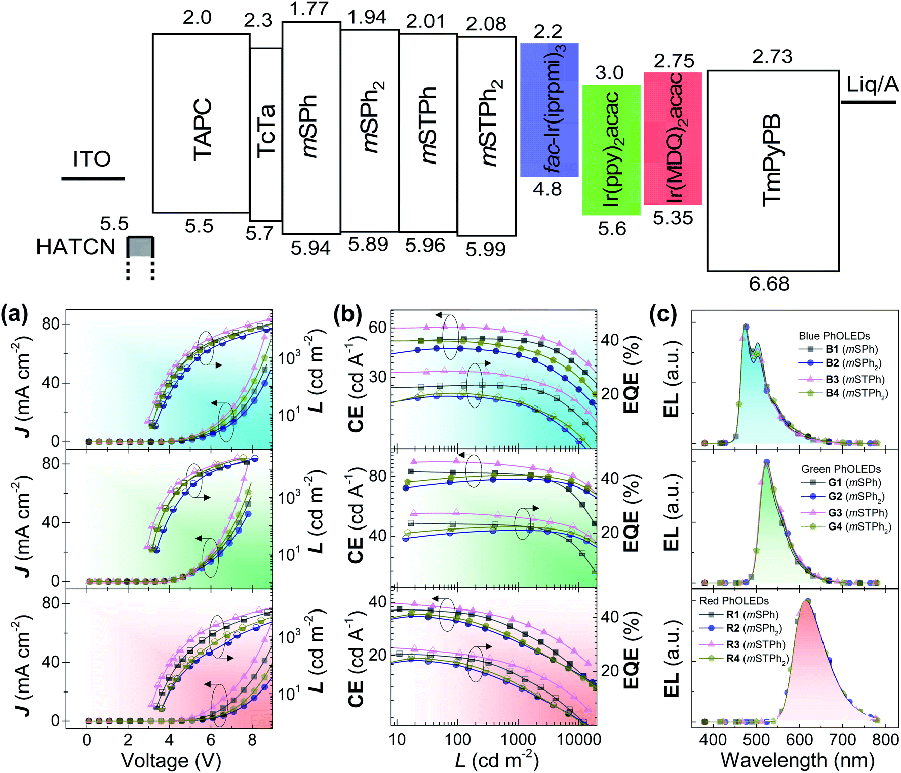 | ||
| Fig. 4 The energy diagram and performance of the devices. (a) Current density–voltage–luminance (J–V–L) curves, (b) current efficiency–luminance–external quantum–efficiency (CE–L–EQE) curves, and (c) EL spectra of the blue (Top), green (Middle) and red (Bottom) PhOLEDs at a current density of 10 mA cm−2. | ||
To interpret the high performance obtained in this series and particularly with mSTPh, photoluminescent lifetimes of the EMLs were investigated (Fig. S3, ESI†). The EMLs of 20 wt% fac-Ir(iprpmi)3 doped into mSPh, mSPh2, mSTPh and mSTPh2 show lifetimes of 1.18, 1.09, 0.86 and 0.95 μs, respectively. Thus, one can note that the lifetime of the EML using mSTPh, 0.86 μs, is considerably reduced compared to others, which might help to reduce the triplet density and the possibility of triplet–triplet annihilation (TTA).32–36 This feature is an important point in the very high device performance obtained. Therefore, the very high performance reached with mSTPh can be assigned to the combination of high ET1, well balanced mobility and short deactivation lifetime.
In order to investigate their potential as universal matrices, these hosts were finally utilized in green (G) and red (R) PhOLEDs. Two iridium complexes namely, bis[2-(2-pyridinyl-N)phenyl-C](acetylacetonato)iridium(III) (Ir(ppy)2acac) (G) and bis(2-methyldibenzo[f,h]quinoxaline)(acetylacetonate) iridium(III) (Ir(MDQ)2acac) (R), were selected as emitters with similar device structures (Devices G1–G4: x = 40, y = 14, z = 45; Devices R1–R4: x = 45, y = 12, z = 55). As shown in Fig. 4, Devices G1–G4 and R1–R4 provide EL peaks of 524 and 612 nm respectively, with negligible spectra shift. All the devices achieve EQEs above 20% and display low Von (Table 2). Again, the highest performance was obtained with mSTPh, which achieved an impressive performance both in green (G3: CEmax = 96.0 cd A−1, PEmax = 101.2 lm W−1, EQEmax = 26%) and in red PhOLEDs (R3: CEmax = 40.0 cd A−1, PEmax = 40.0 lm W−1, EQEmax = 27.3%). The high efficiencies in red PhOLEDs of mSTPh might be due to the red-shifted emission spectrum, which allows increased overlapping over the absorption of the red emitter, facilitating the Förster energy transfer between the host and dopant.37,38 Another reason is that the large LUMO gaps between host/dopant and small LUMO gaps between TmPyPB/dopant of the host and dopant indicate that the dopants can act as direct charge-carrier traps (Fig. S4†). Thus, this additional electron transport channel would lead to better charge balance in the EML, considering the host materials are more hole-dominating.9,39,40 According to our research, this is the highest efficiency ever reported for a universal host material used in RGB OLEDs. As summarized in Table S16 (ESI),† some of the best-performance universal host materials for RGB OLEDs reported to date in the literature are designed with heteroatoms and only a few of them can achieve high EQEs over 20% in all the visible regions.5,9,14,41–49 The results suggest that PHCs can exceed the best universal hosts constructed with conventional heteroatom design principles.
Conclusions
In summary, we proposed PHCs as universal hosts for high-efficiency RGB PhOLEDs. These hosts mSPh, mSPh2, mSTPh and mSTPh2 are constructed by the assembly of the most basic PHC unit, i.e. a benzene ring, in a spiro configuration29,50 and can be easily synthesized in a short and highly efficient manner. We show how the electronic and physical properties can be tuned as a function of the substitution pattern and nature of the substituents. On incorporating the hosts into RGB PhOLEDs, nearly all the devices showed EQEs over 20%, which appeared to be remarkable for devices constructed with PHC materials. In particular, mSTPh achieved the best results with EQEs of 27.3%, 26.0%, 27.1% for RGB PhOLEDs respectively. To the best of our knowledge, this performance of RGB PhOLEDs is the highest reported to date for a universal host (including heteroatom-based hosts). It also proves that PHCs can act as excellent universal hosts without deliberately introducing heteroatoms. Besides, their low cost and simple synthesis are beneficial for large-scale production in the OLED industry. Hopefully, this concept provides new directions in terms of materials design for optoelectronics.Conflicts of interest
There are no conflicts to declare.Acknowledgements
We acknowledge financial support from the National Key R&D Program of China (No. 2016YFB0400700), the National Natural Science Foundation of China (No. 51773141, 51873139 and 21572152), the Natural Science Foundation of Jiangsu Province of China (BK20181442), the CINES (Montpellier No. 2019-A0040805032) for computing time, the CDFIX and CRMPO (Rennes) for X-ray and mass spectra respectively, the ANR (No. 14-CE05-0024-Men In Blue- and No. 19-CE05-0024-SpiroQuest) and the Region Bretagne (DIADEM project) for the PhD grant (FL). This work was also funded by the Collaborative Innovation Center of Suzhou Nano Science & Technology, the Priority Academic Program Development of Jiangsu Higher Education Institutions (PAPD), and the 111 Project.References
- M. A. Baldo, D. F. O'Brien, Y. You, A. Shoustikov, S. Sibley, M. E. Thompson and S. R. Forrest, Nature, 1998, 395, 151–154 CrossRef CAS.
- A. Maheshwaran, V. G. Sree, H.-Y. Park, H. Kim, S. H. Han, J. Y. Lee and S.-H. Jin, Adv. Funct. Mater., 2018, 28, 1802945 CrossRef.
- Q. Wang, Y.-X. Zhang, Y. Yuan, Y. Hu, Q.-S. Tian, Z.-Q. Jiang and L.-S. Liao, ACS Appl. Mater. Interfaces, 2019, 11, 2197–2204 CrossRef CAS PubMed.
- C. Quinton, S. Thiery, O. Jeannin, D. Tondelier, B. Geffroy, E. Jacques, J. Rault-Berthelot and C. Poriel, ACS Appl. Mater. Interfaces, 2017, 9, 6194–6206 CrossRef CAS PubMed.
- C.-C. Lai, M.-J. Huang, H.-H. Chou, C.-Y. Liao, P. Rajamalli and C.-H. Cheng, Adv. Funct. Mater., 2015, 25, 5548–5556 CrossRef CAS.
- F. Lucas, O. A. Ibraikulov, C. Quinton, L. Sicard, T. Heiser, D. Tondelier, B. Geffroy, N. Leclerc, J. Rault-Berthelot and C. Poriel, Adv. Opt. Mater., 2020, 8, 1901225 CrossRef CAS.
- F.-M. Hsu, C.-H. Chien, C.-F. Shu, C.-H. Lai, C.-C. Hsieh, K.-W. Wang and P.-T. Chou, Adv. Funct. Mater., 2009, 19, 2834–2843 CrossRef CAS.
- X. Yang, H. Huang, B. Pan, M. P. Aldred, S. Zhuang, L. Wang, J. Chen and D. Ma, J. Phys. Chem. C, 2012, 116, 15041–15047 CrossRef CAS.
- W.-C. Chen, Y. Yuan, Z.-L. Zhu, Z.-Q. Jiang, S.-J. Su, L.-S. Liao and C.-S. Lee, Chem. Sci., 2018, 9, 4062–4070 RSC.
- Q. Bai, H. Liu, L. Yao, T. Shan, J. Li, Y. Gao, Z. Zhang, Y. Liu, P. Lu, B. Yang and Y. Ma, ACS Appl. Mater. Interfaces, 2016, 8, 24793–24802 CrossRef CAS PubMed.
- M.-k. Leung, Y.-H. Hsieh, T.-Y. Kuo, P.-T. Chou, J.-H. Lee, T.-L. Chiu and H.-J. Chen, Org. Lett., 2013, 15, 4694–4697 CrossRef CAS PubMed.
- M. Romain, C. Quinton, D. Tondelier, B. Geffroy, O. Jeannin, J. Rault-Berthelot and C. Poriel, J. Mater. Chem. C, 2016, 4, 1692–1703 RSC.
- K. Liu, X.-L. Li, M. Liu, D. Chen, X. Cai, Y.-C. Wu, C.-C. Lo, A. Lien, Y. Cao and S.-J. Su, J. Mater. Chem. C, 2015, 3, 9999–10006 RSC.
- J.-J. Huang, Y.-H. Hung, P.-L. Ting, Y.-N. Tsai, H.-J. Gao, T.-L. Chiu, J.-H. Lee, C.-L. Chen, P.-T. Chou and M.-k. Leung, Org. Lett., 2016, 18, 672–675 CrossRef CAS PubMed.
- Y. Zhao, C. Wu, P. Qiu, X. Li, Q. Wang, J. Chen and D. Ma, ACS Appl. Mater. Interfaces, 2016, 8, 2635–2643 CrossRef CAS PubMed.
- X. Ban, W. Jiang, K. Sun, X. Xie, L. Peng, H. Dong, Y. Sun, B. Huang, L. Duan and Y. Qiu, ACS Appl. Mater. Interfaces, 2015, 7, 7303–7314 CrossRef CAS PubMed.
- D. Kondakov, W. Lenhart and W. Nichols, J. Appl. Phys., 2007, 101, 024512 CrossRef.
- N. Lin, J. Qiao, L. Duan, H. Li, L. Wang and Y. Qiu, J. Phys. Chem. C, 2012, 116, 19451–19457 CrossRef CAS.
- N. Lin, J. Qiao, L. Duan, L. Wang and Y. Qiu, J. Phys. Chem. C, 2014, 118, 7569–7578 CrossRef CAS.
- H. Li, M. Hong, A. Scarpaci, X. He, C. Risko, J. S. Sears, S. Barlow, P. Winget, S. R. Marder, D. Kim and J.-L. Brédas, Chem. Mater., 2019, 31, 1507–1519 CrossRef CAS.
- K.-T. Wong, Y.-L. Liao, Y.-T. Lin, H.-C. Su and C.-c. Wu, Org. Lett., 2005, 7, 5131–5134 CrossRef CAS PubMed.
- L.-C. Chi, W.-Y. Hung, H.-C. Chiu and K.-T. Wong, Chem. Commun., 2009, 3892–3894 RSC.
- M. Romain, S. Thiery, A. Shirinskaya, C. Declairieux, D. Tondelier, B. Geffroy, O. Jeannin, J. Rault-Berthelot, R. Metivier and C. Poriel, Angew. Chem., Int. Ed., 2015, 54, 1176–1180 CrossRef CAS PubMed.
- S. Thiery, D. Tondelier, C. Declairieux, G. Seo, B. Geffroy, O. Jeannin, J. Rault-Berthelot, R. Métivier and C. Poriel, J. Mater. Chem. C, 2014, 2, 4156–4166 RSC.
- Z. Zhang, Z. Zhang, D. Ding, Y. Wei, H. Xu, J. Jia, Y. Zhao, K. Pan and W. Huang, J. Phys. Chem. C, 2014, 118, 20559–20570 CrossRef CAS.
- L.-S. Cui, Y.-M. Xie, Y.-K. Wang, C. Zhong, Y.-L. Deng, X.-Y. Liu, Z.-Q. Jiang and L.-S. Liao, Adv. Mater., 2015, 27, 4213–4217 CrossRef CAS PubMed.
- L. J. Sicard, H.-C. Li, Q. Wang, X.-Y. Liu, O. Jeannin, J. Rault-Berthelot, L.-S. Liao, Z.-Q. Jiang and C. Poriel, Angew. Chem., Int. Ed., 2019, 58, 3848–3853 CrossRef CAS PubMed.
- L. Sicard, C. Quinton, J.-D. Peltier, D. Tondelier, B. Geffroy, U. Biapo, R. Métivier, O. Jeannin, J. Rault-Berthelot and C. Poriel, Chem.–Eur. J., 2017, 23, 7719–7727 CrossRef CAS PubMed.
- C. Poriel, L. Sicard and J. Rault-Berthelot, Chem. Commun., 2019, 55, 14238–14254 RSC.
- R. Mertens, The OLED Handbook: A Guide to OLED Technology, Industry & Market, OLED-Info, 2019 Search PubMed.
- J.-H. Lee, C.-H. Chen, P.-H. Lee, H.-Y. Lin, M.-k. Leung, T.-L. Chiu and C.-F. Lin, J. Mater. Chem. C, 2019, 7, 5874–5888 RSC.
- A. Köhler and H. Bässler, Mater. Sci. Eng., R, 2009, 66, 71–109 CrossRef.
- F. Steiner, J. Vogelsang and J. M. Lupton, Phys. Rev. Lett., 2014, 112, 137402 CrossRef PubMed.
- M. A. Baldo, C. Adachi and S. R. Forrest, Phys. Rev. B: Condens. Matter Mater. Phys., 2000, 62, 10967–10977 CrossRef CAS.
- Y.-K. Wang, Q. Sun, S.-F. Wu, Y. Yuan, Q. Li, Z.-Q. Jiang, M.-K. Fung and L.-S. Liao, Adv. Funct. Mater., 2016, 26, 7929–7936 CrossRef CAS.
- Q. Wang, Q.-S. Tian, Y.-L. Zhang, X. Tang and L.-S. Liao, J. Mater. Chem. C, 2019, 7, 11329–11360 RSC.
- S.-H. Liao, J.-R. Shiu, S.-W. Liu, S.-J. Yeh, Y.-H. Chen, C.-T. Chen, T. J. Chow and C.-I. Wu, J. Am. Chem. Soc., 2009, 131, 763–777 CrossRef CAS PubMed.
- J. W. Kim, S. I. You, N. H. Kim, J.-A. Yoon, K. W. Cheah, F. R. Zhu and W. Y. Kim, Sci. Rep., 2014, 4, 7009 CrossRef CAS PubMed.
- N. H. Kim, Y.-H. Kim, J.-A. Yoon, S. Y. Lee, D. H. Ryu, R. Wood, C.-B. Moon and W. Y. Kim, J. Lumin., 2013, 143, 723–728 CrossRef CAS.
- J.-H. Jou, C.-H. Chen, J.-R. Tseng, S.-H. Peng, P.-W. Chen, C.-I. Chiang, Y.-C. Jou, J. H. Hong, C.-C. Wang, C.-C. Chen, F.-C. Tung, S.-H. Chen, Y.-S. Wang and C.-L. Chin, J. Mater. Chem. C, 2013, 1, 394–400 RSC.
- X.-D. Zhu, Y.-L. Zhang, Y. Yuan, Q. Zheng, Y.-J. Yu, Y. Li, Z.-Q. Jiang and L.-S. Liao, J. Mater. Chem. C, 2019, 7, 6714–6720 RSC.
- K. Gao, K. Liu, X.-L. Li, X. Cai, D. Chen, Z. Xu, Z. He, B. Li, Z. Qiao, D. Chen, Y. Cao and S.-J. Su, J. Mater. Chem. C, 2017, 5, 10406–10416 RSC.
- S. Hu, J. Zeng, X. Zhu, J. Guo, S. Chen, Z. Zhao and B. Z. Tang, ACS Appl. Mater. Interfaces, 2019, 11, 27134–27144 CrossRef CAS PubMed.
- C. Wu, B. Wang, Y. Wang, J. Hu, J. Jiang, D. Ma and Q. Wang, J. Mater. Chem. C, 2019, 7, 558–566 RSC.
- X. Qiu, S. Ying, J. Yao, J. Zhou, C. Wang, B. Wang, Y. Li, Y. Xu, Q. Jiang, R. Zhao, D. Hu, D. Ma and Y. Ma, Dyes Pigm., 2020, 174 Search PubMed.
- H.-H. Chou and C.-H. Cheng, Adv. Mater., 2010, 22, 2468–2471 CrossRef CAS.
- S. Gong, Y. Chen, J. Luo, C. Yang, C. Zhong, J. Qin and D. Ma, Adv. Funct. Mater., 2011, 21, 1168–1178 CrossRef CAS.
- S.-J. Su, C. Cai and J. Kido, Chem. Mater., 2011, 23, 274–284 CrossRef CAS.
- W. Song, L. Shi, L. Gao, P. Hu, H. Mu, Z. Xia, J. Huang and J. Su, ACS Appl. Mater. Interfaces, 2018, 10, 5714–5722 CrossRef CAS PubMed.
- C. Poriel and J. Rault-Berthelot, J. Mater. Chem. C, 2017, 5, 3869–3897 RSC.
Footnotes |
| † Electronic supplementary information (ESI) available: General experimental methods, synthesis procedure, X-ray data, TGA and DSC analysis results, photophysical properties, CV curves, transient PL decay curves, molecular modelling, charge mobility calculations, energy level alignment and additional performance data of the OLED device and 1H and 13C NMR spectra of the hosts. CCDC 1495849, 1987304 and 1987305. For ESI and crystallographic data in CIF or other electronic format see DOI: 10.1039/d0sc01238f |
| ‡ Present address: Institut für Physik and IRIS Adlershof, Humboldt-Universität zu Berlin, Brook-Taylor-Str. 6, 12489 Berlin, Germany. |
| This journal is © The Royal Society of Chemistry 2020 |