
 Open Access Article
 This Open Access Article is licensed under a Creative Commons Attribution-Non Commercial 3.0 Unported Licence
Designing an active Ta3N5 photocatalyst for H2 and O2 evolution reactions by specific exposed facet engineering: a first-principles study†
Moussab
Harb
 *,
Luigi
Cavallo
and
Jean-Marie
Basset
*,
Luigi
Cavallo
and
Jean-Marie
Basset
KAUST Catalysis Center (KCC), Physical Sciences and Engineering Division (PSE), King Abdullah University of Science and Technology (KAUST), Thuwal 23955-6900, Saudi Arabia. E-mail: moussab.harb@kaust.edu.sa; Tel: +966-012-8080788
First published on 16th April 2020
Abstract
The effects of native defects and exposed facets on the thermodynamic stability and photocatalytic characteristics of Ta3N5 for water splitting are studied by applying accurate quantum computations on the basis of density functional theory (DFT) with the range-separated hybrid functional (HSE06). Among the three explored potential candidates for O-enriched bulk Ta3N5 structures with substituted O at N sites and accompanied by interstitial O or Ta-vacancies, the first and third structures are relevant. The four possible (001), (010), (100) and (110) low Miller index exposed facets of Ta(3−x)N(5−y)Oy (y = 7x) are also explored, which show lower formation energies than those of Ta3N5. This highlights O occupation at N sites together with Ta vacancies as native defects in the prepared samples. The most appropriate facets for HER and OER are predicted based on the redox and transport characteristics. Our work predicts (001) and (110) facets only for HER, whereas the (010) facet is predicted for OER. Our findings indicate the importance of understanding the significance of various facets when preparing and testing new material photocatalysts for water splitting reactions.
Introduction
The production of hydrogen from water splitting using sunlight and a photocatalytic material is an attractive technology for a new future with clean energy without polluting byproducts.1–5 Although active photocatalysts have been reported for either hydrogen or oxygen evolution reactions, a crucial challenge still remains of the possibility to achieve the two reactions simultaneously, which requires an adequate material to be found. The design of new semiconductor materials with different exposed facets is expected to give different optoelectronic and redox features directly affecting their photocatalytic performance.6–13 For good migration of free carriers to the surface along with minimal electron/hole recombination, the effective masses are needed to be small (near that of the free electron one) along two distinctive crystalline directions.14–16 To drive the electrons for reducing H+ ions and the holes for oxidizing water, the conduction band minimum and the valence band maximum (CBM and VBM) need to be, respectively, located energetically above H+/H2 and below O2/H2O potentials.17 For enhancing the kinetics of electron and hole transfer to water, the co-catalysts for H2 and O2 evolution reactions, OER and HER, should be deposited on the best exposed facets.Tantalum nitride (Ta3N5) is a widely used photocatalyst for solar water splitting, due to its band gap energy of 2.1 eV.18–23 By nitrating Ta2O5 at high temperatures, Ta3N5 powder samples were obtained and the orthorhombic crystal structure was revealed by characterization techniques.18–23 As invoked in the literature, the material could separately generate oxygen or hydrogen from water by the use of sacrificial reagents.18,23 The overall water splitting needs to be carefully examined when using this material in order to overcome the limited efficiency. Photocatalytic measurements are related to the method of sample preparation.20,23 This discrepancy was justified by the presence of unavoidable O impurities in Ta3N5 samples, which originated from Ta2O5 nitridation methods,20,23 leading to defective or non-stoichiometric compounds. One should always be reminded that preparing electrodes using powder materials is not at all easy and leads to a lot of difficulties.19 Ta3N5 flat band potentials were found to be dependent on the photoelectrode fabrication method.23 Because Ta3N5 surfaces tend to be oxidized and the surface oxidation rate may be modified during photocataytic reactions, the expected effects of morphology (nature/type of exposed facets) together with intrinsic defects (such as O impurities and Ta vacancies) on Ta3N5 photoredox reactions need to be well understood. These aspects will be provided in this work via density functional theory (DFT).
In previous theoretical works,24–30 we have studied various fundamental characteristics for solar energy conversion to chemicals with a series of materials commonly utilized in photocatalysis and reproduced with high accuracy the experimental results. This was achieved by performing first-principles computations based on density functional theory (DFT) along with the range-separated hybrid Heyd–Scuseria–Ernzerhof (HSE06)31,32 functional. The choice of the level of theory, in particular, the chosen HSE06 functional, was previously justified based on a systematic comparison with the results obtained using the common standard GGA-PBE functional.24–30 Using this scheme, we recently identified the most appropriate exposed facets of TiO2 (in anatase and rutile phases) for photocatalytic hydrogen and oxygen evolution reactions by combining their optoelectronic and redox properties.33 Our predicted results could successfully give rational insights into the fundamental origin behind the better activity of anatase for HER compared to rutile as found in experiments.33–36
In this paper, we introduce a systematic study on the impact of intrinsic defects and exposed facets on the optoelectronic and redox features of a Ta3N5 water splitting photocatalyst by applying the DFT/HSE06 method. We explored three potential candidates of O-enriched bulk Ta3N5 structures. They are associated with substituted O at N sites (unbalanced charges) and accompanied by interstitial O or Ta-vacancies for the charge balance. By selecting the most relevant bulk structures, we then carried out calculations on the thermodynamic stability, and optoelectronic and redox characteristics for the four possible (001), (010), (100) and (110) low Miler indexes of O-enriched Ta3N5 exposed facets. Moreover, we identified the most appropriate facets for OER and HER reactions and made a comparison with the three principal (023), (310) and (113) facets of prepared Ta3N5 samples. We believe that the concepts resulting from this theoretical study will guide experimentalists in selecting the most suitable exposed facets where the two HER and OER co-catalysts should be anchored for improving reduction of protons and oxidation of water.
Computational models and methods
Bulk models
For bulk Ta3N5, the common orthorhombic crystal lattice with space group Cmcm was used (Fig. 1), as obtained experimentally using different characterization techniques.20 To provide a good description of the required features with minimal possible errors occurring from the periodicity, we have chosen the (3 × 3 × 1) Ta3N5 supercell containing 96 atoms (Ta36N60) for simulation rather than the unit cell (Fig. 2). | ||
| Fig. 1 Atomic structure of bulk Ta3N5 unit cell together with the four possible 〈110〉, 〈100〉, 〈010〉 and 〈001〉 crystallographic directions. Ta is shown in gray, O is shown in red, and N is shown in blue. | ||
 | ||
| Fig. 2 Structures of the low-index pure Ta3N5 exposed facets: (a) (110), (b) (100), (c) (010) and (d) (001). Ta is shown in dark gray and N is shown in blue. In each structure, the coordination numbers of Ta and N surface atoms are highlighted. | ||
Regarding O-enriched bulk Ta3N5 structure simulation, three potential candidates were explored starting from the (3 × 3 × 1) pure Ta3N5 (Ta36N60) supercell. Two substituted O at N sites (Ta36N58O2), two substituted O at N sites together with one interstitial O (Ta36N58O3) and five substituted O at N sites accompanied by one Ta-vacancy (Ta35N55O5). The corresponding stoichiometry Ta(3−x)N(5−y)Oy was adopted with x = 0; y = 0.17 for the first model, x = 0; y = 0.25 for the second one, and x = 0.1; y = 0.5 for the third one, respectively. For each bulk structure, many structural configurations were explored to find the most preferential O location inside the Ta3N5 lattice as well as with respect to the Ta-vacancies.
The thermodynamics of the most relevant Ta(3−x)N(5−y)Oy bulk structures was investigated using the following reaction:
 | (1) |
 | (2) |
 and ETae are the electronic energies of Ta(3−x)N(5−y)Oy, Ta3N5 and pure Ta bulk materials in their lowest-energy structure, respectively.
  and
and  are the O2 and N2 electronic energies, respectively. μO and μN are the oxygen and nitrogen chemical potentials, respectively, which are related to partial pressure and temperature by the entropy and enthalpy corrections as follows:
 | (3) |
Surface models
In the case of pure Ta3N5, (001), (010), (100) and (110) low-index Miller facets were contructed using 2 × 1, 2 × 1, 1 × 1 and 1 × 1 slab models (Fig. 2), respectively. A 15 Å (001) thickness (Ta36N60 or 9 layers; Ta36N60), 15 Å (010) thickness (Ta36N60 or 9 layers), 13 Å (100) thickness (7 layers or Ta42N70) and 14 Å (110) thickness (8 layers or Ta48N80) were allowed to converge towards the bulk properties of the material, as displayed in Fig. S1 (see the ESI† for more details).Regarding the partially O-enriched Ta3N5, (001), (010), (100) and (110) facets were modeled using the obtained optimal thicknesses of pure Ta3N5. A (110) slab model of 14 Å (Ta47N73O7), (100) slab model of 13 Å (Ta41N63O7), (010) slab model of 15 Å (Ta35N53O7) and (001) slab model of 15 Å (Ta35N53O7) were selected on the basis of the number of new sub-coordinated surface N generated upon crystal cleavage together with the most relevant sub-coordinated bulk N species generated after releasing the Ta-vacancy. These four models led to the stoichiometry Ta(3−x)N(5−y)Oy with x = 0.072; y = 0.437 for (110), x = 0.072; y = 0.50 for (100), x = 0.084; y = 0.583 for (010) and x = 0.084; y = 0.583 for (001). For each slab structure, key structural configurations were explored by replacing with O some of the new sub-coordinated 2-fold or 3-fold coordinated surface N that appeared after cleavage and the 3-fold coordinated bulk N sites when Ta-vacancies are present inside the lattice to find the most favorable location of O.
Using reaction (1), we investigated the thermodynamics of the most relevant Ta(3−x)N(5−y)Oy surface structures. We calculated the surface formation energy relative to Ta3N5 as follows:
 | (4) |
 , and ETae are the electronic energies of Ta(3−x)N(5−y)Oy, Ta3N5 and Ta slab materials, respectively, in their most favorable structure with top and bottom identical terminations. A represents the surface area of the slab model.
  ,
,  , ΔμN and ΔμO follow the same definitions as discussed in the Bulk models subsection.
Methods
All bulk and slab structural optimization calculations were done by means of spin-polarized periodic density functional theory (DFT) with the projector-augmented wave (PAW)40 potential and the Perdew–Burke–Ernzerhof (PBE)41 functional using VASP software.42–45 Thermodynamic calculations were carried out using DMol46 software with the double numerical polarization (DNP)47 basis set and the PBE functional. Electronic structure calculations were done using the DFT/HSE06 method with VASP based on the DFT/PBE relaxed geometries. Calculations of relative energy to vacuum were obtained from the DFT/HSE06 local potential profiles along each surface48–53 using VASP software. Calculations of hole/electron effective mass tensors were obtained from the DFT/HSE06-based computed band structure with the VASP software using the finite difference method.54 Details for the various computational techniques adopted in this work are presented in the ESI.†Results and discussion
Atomic/electronic bulk structures and carrier transport features
The orthorhombic crystalline lattice of Ta3N5 is formed by distorted edge-sharing octahedra (Fig. 1).20,23,26,55,56 Each Ta is linked to 3- and 4-coordinated N. The computed bulk lattice constants reproduced well the measured values20,23,26,55,56 (Table 1).| Material | Structure | Formation energy | Lattice constants | |||||
|---|---|---|---|---|---|---|---|---|
| a | b | c | α | β | γ | |||
| Ta3N5 | Expt20,23,26,55,56 | — | 3.89 | 10.22 | 10.28 | 90 | 90 | 90 |
| Ta3N5 | 1(b) | — | 3.89 | 10.25 | 10.27 | 90 | 90 | 90 |
| Ta3N4.83O0.17 | 2(a) | −42.54 | 3.91 | 10.19 | 10.28 | 90 | 90 | 90 |
| Ta3N4.83O0.25 | 2(b) | −57.62 | 3.89 | 10.23 | 10.25 | 89.68 | 90 | 90 |
| Ta2.9N4.6O0.4 | 2(c) | −98.60 | 3.89 | 10.23 | 10.27 | 90 | 90 | 90 |
Considering the Ta3N4.83O0.17 material, the most favorable structure is found when the two 3-fold-coordinated N sites are replaced with O, as shown in Fig. 3a. For this structure, a singlet state associated with two extra paired up electrons in a delocalized state throughout the crystal is found to be the most favorable spin situation. The computed lattice constants are very similar to those of Ta3N5 (Table 1). The structure associated with two O occupying two 4-fold coordinated N was found to be 4.83 kJ mol−1 less stable than that of the previous one.
 | ||
| Fig. 3 Most favorable structures of the three potential partially O-enriched bulk Ta3N5 materials: (a) Ta3N4.83O0.17, (b) Ta3N4.83O0.25 and (c) Ta2.9N4.6O0.4. Ta is shown in dark gray, O is shown in red and N is shown in blue. | ||
Regarding Ta3N4.83O0.25, the geometrical structure is particularly stable when the three O atoms are gathered between two Ta, forming two TaO3N4 polyhedra, one TaO2N5 polyhedron and one TaON5 octahedron (see Fig. 3b). The computed lattice parameters obtained for this structure are also similar to those of pure Ta3N5, except for a small decrease in the angle α, by 0.32° (see Table 1). In this structure, the interstitial O is located nearby the two other substitutional O, occupying two three-coordinated N bridging two Ta. The most favorable spin configuration is a singlet state, leading formally to three O2− defects replacing two N3− species. Another structural configuration derived from two O substituting two separated 4-coordinated N from the interstitial one was found to be 3.86 kJ mol−1 higher than the lowest-energy structure.
With respect to Ta2.9N4.6O0.4, the strong interaction between the Ta-vacancy and the five O was at the origin of its good stability. In the most stable structural configuration, the five O atoms occupying five N sites surround the Ta-vacancy, as displayed in Fig. 3c. The obtained lattice constants are again very similar to those of Ta3N5 (Table 1). For this structure, the most favorable spin situation is found to be a singlet resulting from five O2− replacing five N3− in conjunction with the five holes released from the created Ta vacancy. Note that the geometrical configuration displaying the well-separated five O and the Ta-vacancy was less stable by 9.16 kJ mol−1.
The relative formation energies of the pure materials of Ta3N4.83O0.17, Ta3N4.83O0.25 and Ta2.9N4.6O0.4 were computed at 1200 K (typical annealing temperature for these materials) and values of −42.54, −57.62 and −98.60 kJ mol−1 were obtained, respectively. As their formation energies are much lower than that of pure Ta3N5, it can be clearly concluded that the three potential partially O-enriched bulk structures are thermodynamically more stable than the pure material. This result clearly explains the presence of unavoidable O at N sites with Ta vacancies as intrinsic defects in Ta3N5 samples remaining from Ta2O5 nitridation methods.20,23
For pure Ta3N5, the computed 2.2 eV band gap well reproduced the measured value (2.1 eV)23,26,55,56 (Fig. S2, ESI†).
Considering Ta3N4.83O0.17, the electronic structure analysis shows an n-type conductivity as observed experimentally,23,26 which is represented by pinning up the Fermi level near the CBM of Ta3N5, as shown in Fig. 4a. This phenomenon originates from the newly created donor states made by Ta4+ (5d1) orbitals strongly delocalized over the crystal and located in the 0.7 eV range just below the CBM of Ta3N5. The CBM state is composed of empty Ta5+ (5d0) orbitals and the VBM state consists of filled N3− (2p6) orbitals.
 | ||
| Fig. 4 Electronic density of states (DOS) of the three potential partially O-enriched bulk Ta3N5 materials obtained using the DFT/HSE06 method: (a) Ta3N4.83O0.17, (b) Ta3N4.83O0.25 and (c) Ta2.9N4.6O0.4. Projected DOS is represented by a red curve for O, dark gray for Ta and blue for N. Total DOS is represented by the black curves. CBM and VBM energies are given for each structure. Fermi levels are indicated by black dashed lines. | ||
For Ta3N4.83O0.25, a very similar band gap and similar absolute VBM/CBM energy positions together with orbital contributions dominated by N3− (2p6)/Ta5+ (5d0) were found to those obtained in the case of pure Ta3N5 (Fig. 4b and Fig. S2, ESI†).
With respect to Ta2.9N4.6O0.4, the electronic DOS analysis reveals a slightly broader band gap of 2.3 eV (Fig. 4c) compared with that of the pure material (2.2 eV). Similar to pure Ta3N5, the CBM state is mainly made by Ta5+ (5d0) orbitals and the VBM state is also dominated by occupied N3− (2p6) orbitals due to the minor contributions from O2− (2p6) orbitals in the deeper energy zone of VBM. However, its absolute VBM energy position is shifted downward with respect to that of the pure material one (Fig. 4c and Fig. S2, ESI†) and this is expected to lead to modifications in the redox properties of this material.
Based on the electronic structure results, we focused in what follows on the two relevant partially O-enriched bulk Ta3N5 structures with substituted O at N sites together with Ta vacancies for deeper surface investigation.
Inside the Ta3N5 crystalline lattice, four possible crystallographic directions, 〈110〉, 〈100〉, 〈010〉 and 〈001〉, are present (Fig. 1). An anisotropic nature is highlighted in the mobility of electrons and holes over the four crystalline orientations of Ta3N4.83O0.17 and Ta2.9N4.6O0.4 lattices. The obtained values are reported in Table 2. For electron effective masses, small values of 0.9, 0.7, and 0.7 for Ta3N4.83O0.17 and 0.9, 0.8, and 0.8 for Ta2.9N4.6O0.4 are found in the 〈110〉, 〈010〉 and 〈001〉 directions, while greater values of 2.0 and 2.2 are obtained in the 〈100〉 orientation, respectively. Consequently, a good mobility for electrons on the (110), (010), and (001) facets and a low mobility on the (100) surface are expected. Small effective mass values of holes are obtained in the 〈110〉, 〈010〉 and 〈001〉 orientations of 0.7, 0.9, and 0.9 for Ta3N4.83O0.17 and 0.8, 1.0, and 1.0 for Ta2.9N4.6O0.4, while greater values of 3.6 and 3.9 are found in the 〈100〉 orientation, respectively. Consequently, a good mobility for holes on the (110), (010) and (001) facets and a low mobility on the (100) surface are expected.
| Direction | Ta3N4.83O0.17 | Ta2.9N4.6O0.4 | ||
|---|---|---|---|---|
| (me*/m0)ij | (mh*/m0)ij | (me*/m0)ij | (mh*/m0)ij | |
| 〈110〉 | 0.9 | 0.7 | 0.9 | 0.8 |
| 〈100〉 | 2.0 | 3.6 | 2.2 | 3.9 |
| 〈010〉 | 0.7 | 0.9 | 0.8 | 1.0 |
| 〈001〉 | 0.7 | 0.9 | 0.8 | 1.0 |
The similar trends in the transport properties along the 〈001〉 and 〈010〉 crystal directions may be understood by the similar N and Ta arrangements in the (001)- and (010)-oriented slab structures with similar Ta–Ta and N–N distances (see Fig. 2c and d for more details). The slight discrepancy in the effective masses along the 〈110〉 direction might come from the N and Ta arrangements in the (110)-oriented material structure with longer Ta–Ta and shorter N–N distances (see Fig. 2a). The clear difference in the properties along the 〈100〉 lattice direction with greater effective masses might come from the appearance of parallel planes to the (100) surface. They are positioned according to the longer N–N and Ta–Ta distances in the (100)-oriented structure (see Fig. 2b).
Atomic/electronic surface structures and band alignment for water redox reactions
Four distinctive (110), (100), (010) and (001) low-index Miller exposed facets can be generated on top of the Ta3N5 crystal (Fig. 2). The structures of (110) and (100) facets consist of 3-coordinated N and 5-coordinated Ta, while that of the (010) facet is made by 2-coordinated N with 5-coordinated Ta and the (001) facet structure reveals 2- and 3-coordinated N with 4-coordinated Ta (Fig. 2). The obtained surface energies are 1.65, 1.45, 1.21 and 1.02 J m−2 for the (001), (010), (100) and (110) facets, respectively. The difference is only in the 0.19–0.24 J m−2 range, which means that these surfaces might exist in prepared samples of Ta3N5 and must be considered for deep analysis. Comparing with the principal (023), (310), and (113) surfaces of synthesized Ta3N5 samples having similar coordination numbers of surface species, very close respective values for (310) and (023) to those of (110) or (100) and (010) are obtained.57 This tends to provide a competition between these surfaces. In contrast, the (113) surface energy is found to be higher than the (001) one, which means that (113) is a less stable surface than (001). The presence of only 2-coordinated N with 4-coordinated Ta and very few 3-coordinated Ta makes this surface very sensitive.Regarding the partially O-enriched Ta3N5, different surfaces were built by replacing with O some of the new 2- or 3-fold sub-coordinated generated surface N and the 3-fold coordinated bulk N sites when Ta vacancies are present inside the lattice to find the most favorable location of O. These four models led to the stoichiometry Ta(3−x)N(5−y)Oy with x = 0.072; y = 0.437 for (110), x = 0.072; y = 0.50 for (100), x = 0.084; y = 0.583 for (010) and x = 0.084; y = 0.583 for (001). The most favorable structure of the (110) Ta2.928N4.563O0.437 slab is found when the 3-fold and 2-fold coordinated O exists in the bulk and surrounding the Ta-vacancy (Fig. 5a). For the (100) Ta2.928N4.5O0.5 slab, the most favorable surface structure is partially covered by 3-coordinated O with some 3- and 2-coordinated O inside the bulk located around the Ta-vacancy (Fig. 5b). The most favorable slab structure of (010) Ta2.916N4.417O0.583 is fully covered by 2-coordinated O with some minor O content present in the lattice close to the Ta-vacancy (Fig. 5c). For the (001) Ta2.916N4.417O0.583 slab, the most favorable structure reveals a partially covered surface by 2-coordinated O together with 2- and 3-coordinated O inside the material located around the Ta-vacancy (Fig. 5d). The metastable structure is given in the ESI† (Fig. S3). For the four slab structures, the lowest-energy spin situation is found to be singlet. Bader charge analysis highlighted the appearance of Ta4+ that originated from released electrons after the substitution of O for N, in line with the experimental results.23,26
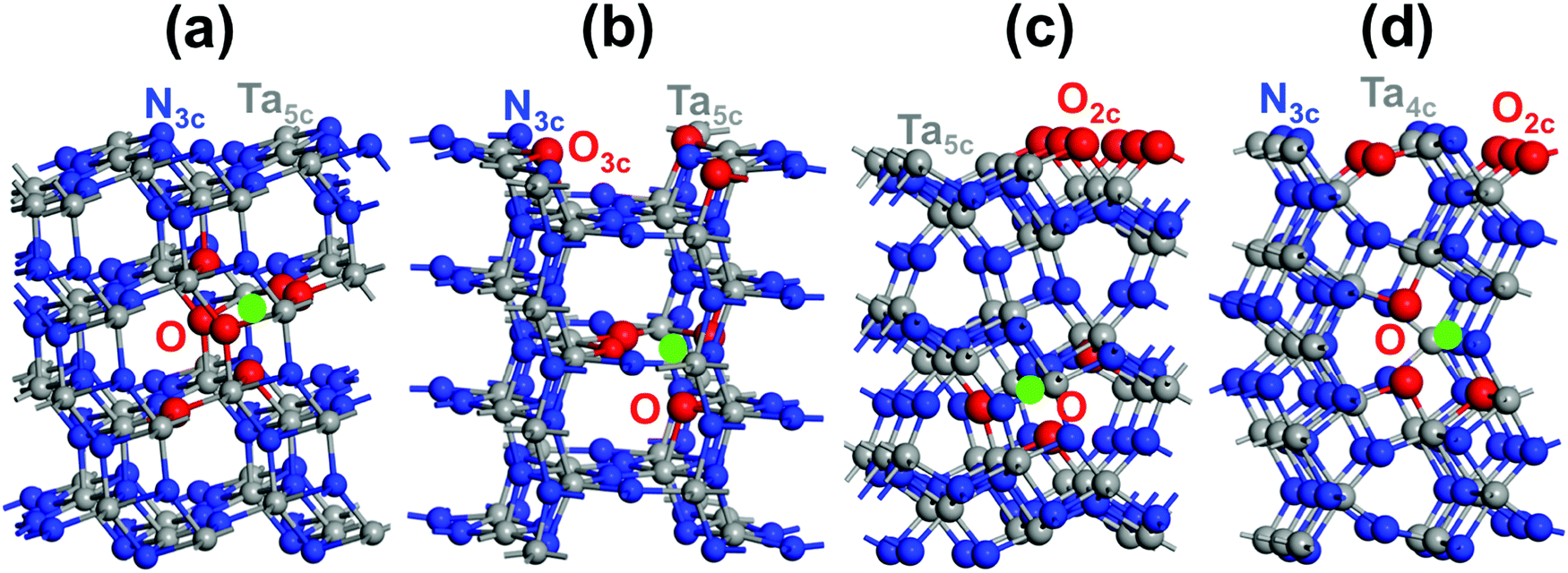 | ||
| Fig. 5 The most favorable structures of the low-index Ta(3−x)N(5−y)Oy exposed facets: (a) (110) Ta2.928N4.563O0.437, (b) (100) Ta2.928N4.5O0.5, (c) (010) Ta2.916N4.417O0.583 and (d) (001) Ta2.916N4.417O0.583. O is shown in red, Ta vacancy is shown in light green, Ta is shown in dark gray and N is shown in blue. For each structure, the coordination numbers of O, N and Ta surface species are highlighted. | ||
The surface formation energy of Ta(3−x)N(5−y)Oy relative to the pure material was computed at 1200 K, which is the typical annealing temperature for this material, and values of −0.18, −0.13, −0.08, −0.07 J m−2 were found for the (001), (010), (100), (110) facets. Indeed, the relative difference is very small, only in the 0.01–0.05 J m−2 range, which highlights that these surfaces might exist in prepared Ta3N5 samples and must be considered for deep analysis. As the obtained relative formation energy values of the different surfaces are negative and even lower than those obtained without Ta-vacancies,57 this confirms, once again from the thermodynamic point of view, the presence of O impurities together with Ta-vacancies in the prepared Ta3N5 samples.20,23
Based on these results, Ta(3−x)N(5−y)Oy facets should be less sensitive than those of Ta3N5 for oxidation. Having mixed O and N or even only O on the surfaces should lead to greater stability when compared to pure material surfaces.
The original band gaps of the (110), (100), (010) and (001) Ta(3−x)N(5−y)Oy slabs were computed and identical values or 0.1 eV broader or 0.6 eV narrower (Fig. 6) were found in comparison with those obtained for the bulk materials (Fig. 4). The VBM/CBM states consist of N3− (2p6)/Ta5+ (5d0) orbitals as found in Ta3N5, while O2− (2p6) orbitals appear lower in the VB states (see Fig. 6). The analysis of their electronic structures highlights the appearance of donor states made by Ta4+ (5d1) orbitals located in the range of 0.4–1.0 eV lower than the CBM of the original material (see Fig. 6). This result leads to a material with n-type conductivity as obtained in experiments.23,26
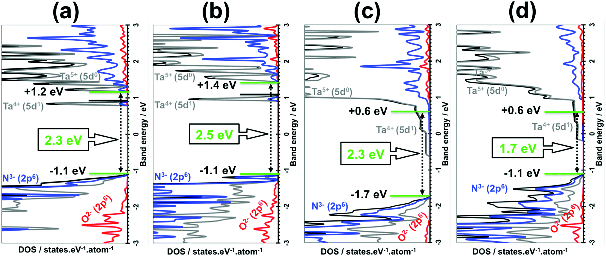 | ||
| Fig. 6 DFT/HSE06-based density of states (DOS) of Ta(3−x)N(5−y)Oy slabs: (a) (110) Ta2.928N4.563O0.437, (b) (100) Ta2.928N4.5O0.5, (c) (010) Ta2.916N4.417O0.583 and (d) (001) Ta2.916N4.417O0.583. Projected DOS is highlighted by the red curve for O, the dark gray curve for Ta and blue for N. Total DOS is highlighted by the black curves. CBM and VBM energies are given in green. Fermi levels are indicated by black lines. For the (010) and (001) facets, the Fermi levels and CBM levels are identical. | ||
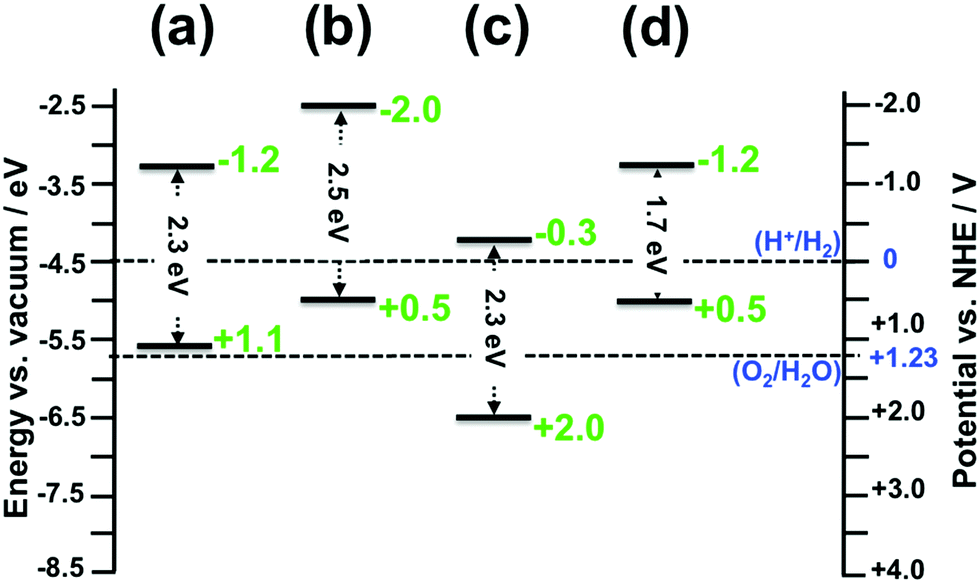
The absolute VBM/CBM energy levels of Ta(3−x)N(5−y)Oy slabs are −1.1/+0.6 eV, −1.7/+0.6 eV, −1.1/+1.4 eV, and −1.1/+1.2 eV, for (001), (010), (100), and (110), respectively, as shown in Fig. 6. Their potential profiles give vacuum energies of 3.9 eV, 4.8 eV, 3.9 eV and 4.5 eV for (001), (010), (100) and (110), respectively, as shown in Fig. 7. The band energy levels of Ta(3−x)N(5−y)Oy slabs are then positioned relative to the vacuum (see the ESI† for more details). An anisotropic nature is highlighted on the basis of exposed facet nature. The VBM energy levels of (001), (100) and (110) slabs are found to be 0.73, 0.73 and 0.13 eV higher than the O2/H2O level (see Fig. 8a, b and d). Their CBM energy level is 1.2, 2.0 and 1.2 eV higher than the H+/H2 level (see Fig. 8a, b and d). In contrast, the (010) VBM level is 0.77 eV below the O2/H2O level and the CBM position is 0.3 eV higher than the H+/H2 potential (Fig. 8c). Due to the inappropriate VBM energy levels of (110), (100) and (001) slabs relative to the O2/H2O level, the generated holes on these surfaces will lose the required driving force for water oxidation. Consequently, these surfaces are predicted as suitable candidates only for HER due to their appropriate CBM level with respect to the H+/H2 level. In contrast, as both CBM and VBM levels of the (010) slab are correctly positioned with respect to the H+/H2 and O2/H2O potentials, respectively, this surface is a suitable candidate for HER and OER. Our computed data for the (010) surface are in good agreement with the measurements achieved recently revealing overall water splitting on Ta3N5 nanorod single crystals grown on the edges of KTaO3 through the (010) surface.58 Following this result, the ability to oxidize water using this material can be maintained by putting an OER co-catalyst on top of the (010) surface. The similar trend in the redox properties between (100) and (001) surfaces comes from the fact that 4- or 5-coordinated Ta and 3-coordinated N with 2- or 3-coordinated O are present on the two surfaces. Interestingly, the small downward shift in the (110) VBM position can be correlated with the three-fold coordinated N species present on this surface. However, the appearance of only 2-fold coordinated O on the (010) surface may explain the drastic change in its redox features with an important downward shift.
 | ||
| Fig. 7 Local potential profiles for Ta(3−x)N(5−y)Oy slabs obtained using the DFT/HSE06 method: (a) (110) Ta2.928N4.563O0.437, (b) (100) Ta2.928N4.5O0.5, (c) (010) Ta2.916N4.417O0.583 and (d) (001) Ta2.916N4.417O0.583. The vacuum energy is given for each exposed facet structure. | ||
 | ||
| Fig. 8 CBM and VBM energy levels relative to the vacuum for Ta(3−x)N(5−y)Oy slabs obtained using the DFT/HSE06 method: (a) (110) Ta2.928N4.563O0.437, (b) (100) Ta2.928N4.5O0.5, (c) (010) Ta2.916N4.417O0.583 and (d) (001) Ta2.916N4.417O0.583. The normal hydrogen electrode (NHE) scale is also displayed for the sake of comparison. | ||
One should be reminded here that very similar electronic and redox properties are obtained for the two (310) and (110) facets and for the two (023) and (010) facets due to the similarities in N and Ta structural distributions on each surface together with the coordination number of surface species.57 The results presented here highlight the impact of each surface on proton reduction or water oxidation depending on the chemical element structural distribution and the surface species coordination number.
As defined in the introduction, the co-catalysts for H2 and O2 evolution reactions must be, in principle, deposited over promising surfaces to improve the kinetics of electron and hole transfer to water solution. Obtaining such an anisotropic nature in the optoelectronic and redox features makes water splitting more complex.59,60 Consequently, by merging the optoelectronic and redox properties together, our work indicates the (010) surface as being the only appropriate candidate for OER, whereas the two (110) and (001) Ta(3−x)N(5−y)Oy surfaces are the most appropriate candidates for HER. The 5- and 4-coordinated Ta exposed species would be the active sites for proton reduction towards HER on the two (110) and (001) surfaces, respectively. The 2-coordinated O exposed species would be the active site for water oxidation towards OER on the (010) surface. The increase or decrease in the number of defects is expected to minimally affect the number of active sites and, therefore, the overall activity of the photocatalyst.
Having suitable flat band potentials of Ta3N5 powder samples relative to water redox limits cannot ensure an active photocatalytic material for water splitting reactions because of the anisotropic behavior of its redox and optoelectronic features and their direct relation with the type/nature of exposed facets. The low efficiency for water splitting obtained so far using this material can be supported by the obtained results from this work. The most effective way to overcome the water splitting efficiency limitation requires a deposition of the co-catalyst for OER on the (010) surface and that for HER either on the (110) or (001) surface.
Conclusions
We investigated the impact of native defects and exposed facets on the thermodynamic stability, and optoelectronic and redox characteristics of the Ta3N5 photocatalyst for solar water splitting. This was achieved by applying accurate DFT/HSE06-based first-principles calculations. Among the three explored potential candidates for O-enriched bulk Ta3N5 structures associated with substituted O species at N sites and accompanied by interstitial O or Ta-vacancies, the first and third structures were relevant. Four possible (001), (010), (100) and (110) low Miller index surfaces for Ta(3−x)N(5−y)Oy (y = 7x) were then investigated and they revealed lower formation energies than those of the pure Ta3N5, which highlights the presence of O at N sites together with Ta vacancies as native defects in the prepared samples. Merging the anisotropic character of the redox and optoelectronic features led to the identification of the promising facets for H2 and O2 evolution reactions.Our study predicted the two (110) and (001) Ta(3−x)N(5−y)Oy surfaces as being the most appropriate candidates for HER due to appropriate CBM levels with respect to the H+/H2 level together with good accumulation of photogenerated electrons, whereas the (010) surface was the only appropriate candidate for OER due to its appropriate VBM level with respect to the O2/H2O level along with good accumulation of photogenerated holes.
In summary, our work indicates that different facets can have remarkably different photophysico-chemical properties, with an impact on their potential performance in HER and OER. This concept will help experimentalists in choosing the appropriate exposed facets where the HER and OER co-catalysts should be anchored.
Conflicts of interest
The authors declare no competing financial interest.Acknowledgements
This research project was carried out at the King Abdullah University of Science and Technology (KAUST). We warmly thank the KAUST Supercomputing Laboratory (KSL) for the computational time granted to this work.References
- K. Maeda and K. Domen, J. Phys. Chem. C, 2007, 111, 7851–7861 CrossRef CAS.
- A. J. Esswein and D. G. Nocera, Chem. Rev., 2007, 107, 4022–4047 CrossRef CAS PubMed.
- A. Kudo and Y. Miseki, Chem. Soc. Rev., 2009, 38, 253–278 RSC.
- K. Maeda and K. Domen, J. Phys. Chem. Lett., 2010, 1, 2655–2661 CrossRef CAS.
- H. Tong, S. Ouyang, Y. Bi, N. Umezawa, M. Oshikiri and J. Ye, Adv. Mater., 2012, 24, 229–251 CrossRef CAS PubMed.
- T. Ohno, K. Sarukawa and M. Matsumura, New J. Chem., 2002, 26, 1167–1170 RSC.
- R. Li, F. Zhang, D. Wang, J. Yang, M. Li, J. Zhu, X. Zhou, H. Han and C. Li, Nat. Commun., 2013, 4, 1432 CrossRef PubMed.
- J. Yu, J. Low, W. Xiao, P. Zhou and M. Jaroniec, J. Am. Chem. Soc., 2014, 136, 8839–8842 CrossRef CAS PubMed.
- S. Gao, W. Wang, Y. Ni, C. Lu and Z. Xu, J. Alloys Compd., 2015, 647, 981–988 CrossRef CAS.
- C. Li, C. Koenigsmann, W. Ding, B. Rudshteyn, K. P. Yang, K. P. Regan, S. J. Konezny, V. S. Batista, G. W. Brudvig, C. A. Schmuttenmaer and J.-H. Kim, J. Am. Chem. Soc., 2015, 137, 1520–1529 CrossRef CAS PubMed.
- W. Wang, J. Fang, Y. Zhou, W. Zhang and C. Lu, RSC Adv., 2016, 6, 67556–67564 RSC.
- W. Li, K. R. Yang, X. Yao, Y. He, Q. Dong, G. W. Brudvig, V. S. Batista and D. Wang, ACS Appl. Mater. Interfaces, 2019, 11, 5616–5622 CrossRef CAS PubMed.
- S. Wang, G. Liu and L. Wang, Chem. Rev., 2019, 119, 5192–5247 CrossRef CAS PubMed.
- O. Madelung, Semiconductors: Data Handbook, Springer, New York, 3rd edn, 2004, pp. 1–691 Search PubMed.
- S. Adashi, GaAs and Related Materials, World Scientific Publishing Co. Pvt. Ltd, Singapore, 1994 Search PubMed.
- I. Vurgaftman, J. R. Meyer and L. R. Ram-Mohan, J. Appl. Phys., 2001, 89, 5815–5875 CrossRef CAS.
- A. L. Linsebigler, G. Lu and J. T. Yates, Chem. Rev., 1995, 95, 735–758 CrossRef CAS.
- M. Hara, G. Hitoki, T. Takata, J. N. Kondo, H. Kobayashi and K. Domen, Catal. Today, 2003, 78, 555–560 CrossRef CAS.
- W.-J. Chun, A. Ishikawa, H. Fujisawa, T. Takata, J. N. Kondo, M. Hara, M. Kawai, Y. Matsumoto and K. Domen, J. Phys. Chem. B, 2003, 107, 1798–1803 CrossRef CAS.
- S. J. Henderson and A. L. Hector, J. Solid State Chem., 2006, 179, 3518–3524 CrossRef CAS.
- L. Yuliati, J.-H. Yang, X. Wang, K. Maeda, T. Takata, M. Antonietti and K. Domen, J. Mater. Chem., 2010, 20, 4295–4298 RSC.
- C.-T. Ho, K.-B. Low, R. F. Klie, K. Maeda, K. Domen, R. J. Meyer and P. T. Snee, J. Phys. Chem. C, 2010, 115, 647–652 CrossRef.
- E. Nurlaela, S. Ould-Chikh, M. Harb, S. del Gobbo, M. Aouine, E. Puzenat, P. Sautet, K. Domen, J.-M. Basset and K. Takanabe, Chem. Mater., 2014, 26, 4812–4825 CrossRef CAS.
- M. Harb, P. Sautet and P. Raybaud, J. Phys. Chem. C, 2011, 115, 19394–19404 CrossRef CAS.
- M. Harb, D. Masih, S. Ould-Chikh, P. Sautet, J.-M. Basset and K. Takanabe, J. Phys. Chem. C, 2013, 117, 17477–17484 CrossRef CAS.
- M. Harb, P. Sautet, E. Nurlaela, P. Raybaud, L. Cavallo, K. Domen, J.-M. Basset and K. Takanabe, Phys. Chem. Chem. Phys., 2014, 16, 20548–20560 RSC.
- A. Ziani, M. Harb, D. Noureldine and K. Takanabe, Appl. Phys. Lett., 2015, 3, 096101 Search PubMed.
- D. Noureldine, S. Lardhi, A. Ziani, M. Harb, L. Cavallo and K. Takanabe, J. Mater. Chem. C, 2015, 3, 12032–12039 RSC.
- S. Lardhi, D. Noureldine, M. Harb, A. Ziani, L. Cavallo and K. Takanabe, J. Chem. Phys., 2016, 144, 134702 CrossRef PubMed.
- M. Harb and L. Cavallo, ACS Omega, 2018, 3, 18117–18123 CrossRef CAS PubMed.
- J. Heyd, G. E. Scuseria and M. Ernzerhof, J. Chem. Phys., 2003, 118, 8207–8215 CrossRef CAS.
- J. Heyd, G. E. Scuseria and M. Ernzerhof, J. Chem. Phys., 2006, 124, 219906 CrossRef.
- M. Harb, G. Jeantelot and J.-M. Basset, J. Phys. Chem. C, 2019, 123, 28210–28218 CrossRef CAS.
- T. Luttrell, S. Halpegamage, J. Tao, A. Kramer, E. Sutter and M. Batzill, Nat. Sci. Rep., 2014, 4, 4043 CrossRef PubMed.
- A. Sclafani and J. M. Hermann, J. Phys. Chem., 1996, 3654, 13655–13661 CrossRef.
- L. Kavan, M. Gratzel, S. E. Gilbert, C. Klemenz and H. J. Scheel, J. Am. Chem. Soc., 1996, 118, 6716–6723 CrossRef CAS.
- M. Harb, P. Sautet and P. Raybaud, J. Phys. Chem. C, 2013, 117, 8892–8902 CrossRef CAS.
- H. Zhu, D. C. Rosenfeld, M. Harb, D. H. Anjum, M. N. Hedhili, S. Ould-Chikh and J.-M. Basset, ACS Catal., 2016, 6, 2852–2866 CrossRef CAS.
- J.-W. Jang, D. Friedrich, S. Müller, M. Lamers, H. Hempel, S. Lardhi, Z. Cao, M. Harb, L. Cavallo, R. Heller, R. Eichberger, R. van der Krol and F. F. Abdi, Adv. Energy Mater., 2017, 7, 1701536 CrossRef.
- P. E. Blöchl, Phys. Rev. B: Condens. Matter Mater. Phys., 1994, 50, 17953–17979 CrossRef PubMed.
- J. P. Perdew, K. Burke and M. Ernzerhof, Phys. Rev. Lett., 1996, 77, 3865–3868 CrossRef CAS PubMed.
- G. Kresse and J. Hafner, Phys. Rev. B: Condens. Matter Mater. Phys., 1994, 49, 14251–14269 CrossRef CAS PubMed.
- G. Kresse and J. Furthmüller, Phys. Rev. B: Condens. Matter Mater. Phys., 1996, 54, 11169–11186 CrossRef CAS PubMed.
- G. Kresse and J. Furthmüller, Comput. Mater. Sci., 1996, 6, 15–50 CrossRef CAS.
- G. Kresse and D. Joubert, Phys. Rev. B: Condens. Matter Mater. Phys., 1999, 59, 1758–1775 CrossRef CAS.
- B. Delley, J. Chem. Phys., 2000, 113, 7756–7764 CrossRef CAS.
- B. Delley, J. Chem. Phys., 1990, 92, 508–517 CrossRef CAS.
- C. G. Van de Walle and R. M. Martin, Phys. Rev. B: Condens. Matter Mater. Phys., 1987, 35, 8154–8165 CrossRef CAS PubMed.
- A. Franciosi and C. G. Van de Walle, Surf. Sci. Rep., 1996, 25, 1–140 CrossRef CAS.
- J. Rossmeisl, E. Skúlason, M. E. Björketun, V. Tripkovic and J. K. Nørskov, Chem. Phys. Lett., 2008, 466, 68–71 CrossRef CAS.
- V. Stevanovic, S. Lany, D. S. Ginley, W. Tumasb and A. Zungerc, Phys. Chem. Chem. Phys., 2014, 16, 3706–3714 RSC.
- T. A. Pham, Y. Ping and G. Galli, Nat. Mater., 2017, 16, 401–408 CrossRef CAS PubMed.
- G. Makov and M. C. Payne, Phys. Rev. B: Condens. Matter Mater. Phys., 1995, 51, 4014–4022 CrossRef CAS PubMed.
- A. Fonari and C. Sutton, Effective Mass Calculator for Semiconductors, http://afonari.com/emc/.
- M. Harb, L. Cavallo and J.-M. Basset, J. Phys. Chem. C, 2014, 118, 20784–20790 CrossRef CAS.
- E. Nurlaela, M. Harb, S. del Gobbo, M. Vashishta and K. Takanabe, J. Solid State Chem., 2015, 229, 219–227 CrossRef CAS.
- M. Harb and J.-M. Basset, J. Phys. Chem. C, 2020, 124, 2472–2480 CrossRef CAS.
- Z. Wang, Y. Inoue, T. Hisatomi, R. Ishikawa, Q. Wang, T. Takata, S. Chen, N. Shibata, Y. Ikuhara and K. Domen, Nat. Catal., 2018, 1, 756–763 CrossRef CAS.
- H. Wang, L. Qiao, H. Xu, Y. Lin, Y. Shen and C. Nan, Soft Nanosci. Lett., 2016, 6, 11–30 CrossRef CAS.
- D. Kim, B. C. Yeo, D. Shin, H. Choi, S. Kim, N. Park and S. S. Han, Phys. Rev. B, 2017, 95, 045209 CrossRef.
Footnote |
| † Electronic supplementary information (ESI) available: Computational details for the different methods used in this work. Convergence tests of the electronic properties of (001), (010), (100) and (110) pure Ta3N5 slabs with crystal thickness based on the DFT/PBE method. Electronic structure of bulk Ta3N5 crystal using the DFT/HSE06 method. DFT/PBE-based metastable slab atomic structures of (110), (100), (010) and (001) partially O-enriched Ta3N5 facets. See DOI: 10.1039/d0cp01394c |
| This journal is © the Owner Societies 2020 |