DOI:
10.1039/C9BM01787A
(Review Article)
Biomater. Sci., 2020,
8, 1783-1801
Microfluidics for ZnO micro-/nanomaterials development: rational design, controllable synthesis, and on-chip bioapplications
Received
5th November 2019
, Accepted 13th January 2020
First published on 14th January 2020
Abstract
Zinc oxide (ZnO) materials hold great promise in diverse applications due to their attractive physicochemical features. Recent years, especially the last decade, have witnessed considerable progress toward rational design and bioapplications of multiscale ZnO materials through microfluidic techniques. Design of a microfluidic device that allows for precise control over reaction conditions could not only yield ZnO particles with a fast production rate and high quality, but also permit downstream applications with desirable and superior performance. This review summarizes microfluidic approaches for the synthesis and applications of ZnO micro-/nanomaterials. In particular, we discuss the recent achievement of using microfluidic reactors in the controllable synthesis of ZnO structures (wire, rod, sphere, flower, sheet, flake, spindle, and ellipsoid), and highlight the unprecedented opportunities for applying them in biosensing, biological separation, and molecular catalysis applications through microfluidic chips. Finally, major challenges and potential opportunities are explored to guide future studies in this area.
 Nanjing Hao | Dr Nanjing Hao joined the Dartmouth College as a research associate in 2016 under the supervision of Prof. John X. J. Zhang. He is currently working at the Duke University. He obtained his bachelor's degree of bioengineering in 2009 and PhD degree of chemistry in 2014. His research interest is focused on microfluidics-enabled on-chip colloidal materials synthesis for applications in liquid biopsy, biosensors, catalysis, and environment. |
 Michael Zhang | Michael Zhang is a current IV Form student at the Lawrenceville School, NJ, where he leads student clubs on debates and robotics, and is on the editorial board of the science journal Lawrencium. He is interested in the design of smart nanomaterials for environmental, soft robot and biomedical applications. His research internship at Dartmouth College is on developing zinc oxide based nanomaterials for water purification, for which he won the Stockholm Junior Water prize in 2019. |
 John X. J. Zhang | John X. J. Zhang is a Professor at the Thayer School of Engineering, Dartmouth College, NH, USA, and a Fellow of AIMBE. He received his PhD from Stanford University, CA, USA. His research is on developing miniature medical systems to improve global health, through innovations in bio-inspired nanomaterials, lab-on-chip design, and advanced nanofabrication technologies. He is a recipient of numerous prestigious awards, including the NSF Career award, DARPA Young Faculty Award, Wallace Coulter Foundation Early Career Award and NIH Director's Transformative Research Award. His recent translational effort with industry led to the Facebook SARA award, Sony Faculty Innovation Award, and Agilent University Research Award. Dr Zhang has mentored over 30 Ph.D. students and post-doctoral scholars, and published a textbook in biomedical engineering. |
1. Introduction
Zinc oxide (ZnO) micro-/nanomaterials have attracted great attention from materials scientists and engineers due to their remarkable properties and wide potential applications in optoelectronics,1 energy,2 biomedical engineering,3 catalysis and environment.4 To date, a large variety of ZnO materials with distinct physicochemical properties have been developed using methods such as hydrothermal, sol–gel, supercritical fluid, spray pyrolysis, biosynthesis, and physical/chemical vapor deposition methods.5,6 Taking advantage of well-established batch processes and rich kinds of reactant systems, ZnO structures with controllable sizes (from a few nanometers to tens of micrometers) and shapes (such as wire, rod, sphere, ellipsoid, flower, cube, sheet, and plate) are already available. However, owing to the relatively low reproducibility and poor control over conventional batch reaction processes, there is still great demand to develop delicate and elaborate methods for meeting the practical needs of diverse fields.
The emergence of microfluidics brings a variety of new and attractive features that conventional batch systems can hardly achieve, such as real-time spatio-temporal control, high flexibility and integration capability, and low sample consumption.7–10 From the upstream materials synthesis point of view, microfluidics-based microreactors could offer many unique advantages over conventional flask-based batch reactors. For example, rapid reaction kinetics and dedicated control of reaction parameters enable fast screening and optimization of materials properties; greatly reduced reactor dimensions and large surface-to-volume ratios of microchannels allow enhanced mass/heat transfer, leading to minimal batch-to-batch differences and high yields; and working at elevated temperatures and pressures while confining potentially active starting reactants gives great chances to create new materials.11–20 Therefore, microreactors have been widely employed for controllable synthesis of polymers,21–27 gold,28,29 quantum dots,30,31 magnetic materials,32 and silica materials.33 Similarly, from the downstream application point of view, microfluidics-based microchips could provide many superior benefits over conventional batch approaches, such as high sensitivity and specificity, rapid response time, simple sample pretreatment, and low sample consumption. These features endow microchips with promising potential applications in sensing,34,35 catalysis,28,36 nanomedicine,25 drug delivery,37–40 tissue engineering,24 and many other biomedical fields.20,41–44
This review first presents an overview of recent progress in the synthesis and applications of ZnO micro-/nanomaterials using microfluidics. We start by summarizing the established continuous and discrete microreactor systems for the rational design and controllable synthesis of ZnO structures, followed by highlighting the unprecedented opportunities of microchips in myriad applications of biosensing, biological separation, and molecular catalysis, and finally providing in-depth discussions of current challenges and opportunities for guiding future research.
2. Microfluidics fundamentals
Since their emergence in the early 1980s, microfluidics technologies have become promising tools for a variety of applications.7 Due to scaling down in dimensions, the fluid behavior is primarily dominated by viscosity rather than inertia, and a high surface-to-volume ratio enables rapid mass and heat transfer in microfluidic devices. These features provide great opportunities in the field of synthetic and analytical chemistry, biology, and engineering sciences.
For on-chip materials synthesis and applications of ZnO, the Reynolds number (Re) that gives a measure of the ratio of inertial forces to viscous forces is usually used to predict the flow conditions. The Reynolds number is expressed as Re = ρUL/μ, where ρ is the fluid density, U is the flow velocity, L is the characteristic length of a microchannel, and μ is the fluid dynamic viscosity. Generally, flow in microfluidic reactors is always laminar due to the microscale dimensions. Although the laminar flow inside microfluidic devices allows for more controllable reactions, it causes obvious diffusion-limited mixing of reactants. To overcome this inherent issue, active or passive mixing modules are proposed in different forms.14,20 Optimizing the design of microfluidic reactors toward enhanced mixing performance is guided by the Péclet number (Pe) that represents the ratio of advection and diffusion caused by heat transfer. The Péclet number can be expressed as Pe = UL/D, where U is an average flow velocity, L is a representative length scale, and D is the diffusion coefficient. Since the typical values of U, L, and D in microchannels are ∼1 m s−1, 10−6–10−4 m, and 10−10–10−11 m2 s−1, respectively, the Pe of microfluidic devices is thus relatively large enough to neglect the diffusion-limited mixing.33 To improve the mixing performance of reactants for ZnO production, one common strategy is to increase the length of microchannels (such as winding or serpentine form). Given the homogeneous reaction environment from microfluidics, the production efficiency and working performance of the resultant materials are generally higher than those from conventional batch reactors. Therefore, microfluidics provides an excellent platform for rational design, controllable synthesis, and on-chip applications of functional ZnO materials.
The development of microfluidic devices followed the continuously growing demand for the synthesis and application of micro-/nanoparticles. The rapid growth of microfabrication techniques has led to the revolution of microfluidic reactors for ZnO materials synthesis and microfluidic chips for on-chip applications. The simplest design started with tubular straight microreactors made of glass capillary and stainless steel, which had the obvious advantages of low cost and easy scaling up. However, they could not meet the needs for complicated reactions, which thus stimulated the progress of polydimethylsiloxane (PDMS)-based microreactors fabricated by means of lithography techniques.45 The combination of tubular and PDMS microreactors has also been utilized in some cases for meeting the synthesis and on-chip application requirements. However, there is still much room in microfluidic synthesis and application of ZnO micro-/nanomaterials.
3. Microfluidic synthesis of ZnO materials
Compared to conventional batch reactors (Fig. 1A), microreactors could execute precise spatial-temporal control over experimental parameters such as microchannel dimensions, temperature, pressure, and flow rate, which enables the continuous synthesis of high quality ZnO micro-/nanoparticles with well-defined physicochemical properties. By virtue of their appealing features, microreactors have already successfully demonstrated the effectiveness of microfluidic approaches in the controllable production of ZnO materials with different sizes ranging from a few nanometers to tens of micrometers and various shapes such as wire, sphere, rod, flower, spindle, ellipsoid, and sheet (Table 1). Generally, microreactors for ZnO materials synthesis could be broadly grouped into two main categories: (1) continuous laminar flow microreactors that involve only one single phase aqueous fluid with two or multiple inlets for different reactants (Fig. 1B); and (2) discrete segmented flow microreactors that usually include one or more aqueous reactant fluids as inlets and one oil/gas phase for isolating aqueous flows (Fig. 1C). Microreactors that introduce an immiscible oil flow as a carrier liquid with several liquid flows of reactants are known as droplet flow microreactors (Fig. 1C, left), while ones that include one gas phase flow to generate different segments of reactants are known as segmented flow microreactors (Fig. 1C, right). In the following, we will systematically summarize the established microfluidic systems for the flow synthesis of ZnO micro-/nanoparticles.
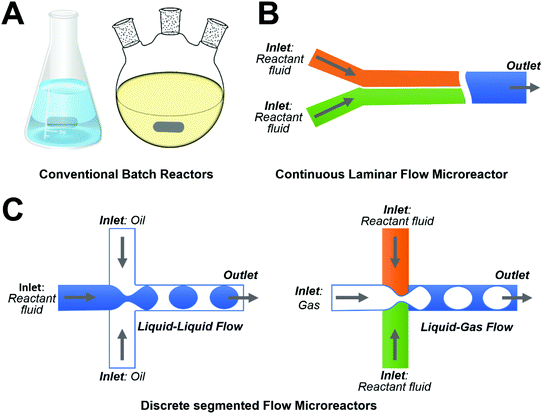 |
| | Fig. 1 Schematic illustrations showing examples of different types of reactors: (A) conventional batch reactors; (B) continuous laminar flow microreactors; and (C) discrete segmented flow microreactors. | |
Table 1 Synthesis of ZnO materials using microfluidic reactors
| Microreactor type |
Particle type |
Particle size |
Particle shape |
Reaction conditions |
Key precursors |
Ref. (by year) |
| Abbreviations: DMF: dimethyl formamide; HMT: hexamethylenetetramine; OA: oleic acid; OL: oleylamine; PAA: poly(acrylic acid); PEI: polyethylenimine; R.T.: room temperature; and TOP: trioctylphosphine. |
| T-shaped mixer |
ZnO |
9 nm |
Near-sphere |
673 K; 30 MPa |
ZnSO4 + KOH |
200446 |
| T-shaped mixer |
ZnO |
∼3 μm |
Flower |
90 °C |
Zn(OAc)2 + NaOH |
200847 |
| Microchamber |
ZnO |
100 nm × (0.5–3 μm) |
Wire |
90 °C; 0.72–2.88 mL h−1 |
Zn(NO3)2 + HMT |
200948 |
| Microchamber |
ZnO |
(80–100 nm) × (70–860 nm) |
Wire |
90 °C |
Zn(NO3)2 + HMT |
200949 |
| Y-shaped mixer |
ZnO |
(50–100 nm) × 1.5 μm |
Wire |
60–150 °C; 10–25 μL min−1 |
Zn(OAc)2 + NaOH; Zn(NO3)2 + HMT |
201050 |
| Coflowing reactor |
ZnO |
∼4 nm |
Sphere |
250 °C; 25 MPa |
Zn(acac)2 + TOP/OL/OA |
201151 |
| T-junction |
ZnO |
∼0.4–4 μm |
Sphere; cylinder; star; flower |
90–150 °C; 250–3000 μL min−1 |
Zn(OAc)2 + NaOH |
201152 |
| Straight microchannel |
ZnO |
(50–100 nm) × (5–6 μm) |
Wire |
90–95 °C; 0.5–1 μL min−1 |
Zn(NO3)2 + HMT + PEI |
201153 |
| Microdot array; micropost array |
ZnO |
(100–200 nm) × (2–3 μm) |
Wire |
95 °C |
Zn(NO3)2 + HMT + PEI |
201254 |
| T-shaped mixer |
ZnO |
∼5 nm–1 μm |
Sphere; tactoid |
70 °C; 6.8–28.1 mL min−1 |
Zn(NO3)2 + NaOH |
201355 |
| Membrane dispersion reactor |
ZnO |
7–26 nm |
Near-sphere |
R.T.; 10–50 mL min−1 |
ZnSO4 + NH4HCO3 |
201356 |
| Straight microchannel |
ZnO |
∼80 nm × 4 μm |
Wire |
85–90 °C |
DMF |
201357 |
| Straight microchannel |
ZnO |
Up to 11.2 μm in length |
Wire |
85 °C; 0.55–0.91 mL min−1 |
Zn(NO3)2 + hexamine |
201358 |
| T-shaped mixer |
ZnO![[thin space (1/6-em)]](https://www.rsc.org/images/entities/char_2009.gif) : :![[thin space (1/6-em)]](https://www.rsc.org/images/entities/char_2009.gif) Na Na |
3–4 μm |
Flower |
80 °C; 6.5 mL min−1 |
Zn(NO3)2 + NaOH |
201359 |
| Microchamber |
ZnO |
(100–200 nm) × 20 μm |
Wire |
95 °C |
Zn(NO3)2 + HMT + PEI |
201360 |
| Microchamber |
ZnO |
(50–200 nm) × (1–1.5 μm) |
Wire |
385 K |
Zn(NO3)2 + HMT |
201461 |
| Y-junction |
ZnO |
10–20 nm |
Near-sphere |
40–70 °C; 1–7 mL min−1 |
Zn(NO3)2/ZnSO4/ZnCl2 + NaOH |
201462 |
| T-shaped mixer |
ZnO |
∼3–5 μm |
Flower; wire |
70 °C; 6.8–28.1 mL min−1 |
Zn(OAc)2 + NaOH |
201463 |
| T-shaped mixer; winding channel |
ZnO |
3–5 nm |
Sphere |
60 °C; 0.855–1.645 μL min−1 |
Zn(OAc)2 + NaOH |
201464 |
| Straight microchannel |
ZnO |
50 nm × 3 μm |
Wire |
95 °C; 1–1000 mm s−1 |
Zn(NO3)2 + HMT + PEI |
201565 |
| Microchamber |
ZnO![[thin space (1/6-em)]](https://www.rsc.org/images/entities/char_2009.gif) : :![[thin space (1/6-em)]](https://www.rsc.org/images/entities/char_2009.gif) Al Al |
(70–140 nm) × (3.9–4.7 μm) |
Flake |
80 °C; 2 mL h−1 |
Zn(NO3)2 + Al(NO3)3 + NH4Cl |
201566 |
| Y-shaped mixer |
ZnO |
(100–150 nm) × (1–2 μm) |
Wire |
60–150 °C; 10–25 μL min−1 |
Zn(OAc)2 + NaOH + Zn(NO3)2 + HMT |
201667 |
| T-shaped mixer |
ZnO |
(50–500 nm) × (0.24–16.6 μm) |
Wire |
70–80 °C; 6.8–28.1 mL min−1 |
Zn(OAc)2 + NaOH |
201668 |
| T-shaped mixer; cross-type mixer |
ZnO–Ag |
500 nm |
Hedgehog |
100 °C; 1 mL min−1 |
Zn(NO3)2 + NaOH + AgNO3 + NaBH4 |
201669 |
| Y-shaped mixer |
ZnO |
2–3 nm |
Sphere |
180 W ultrasonic power; 20–60 °C |
Zn(OAc)2 + LiOH |
201670 |
| Straight microchannel |
ZnO |
∼100 nm × (1–2 μm) |
Sharp end; wire; hexahedral-puncheon |
750 μL h−1; 60 °C |
ZnSO4 + NH4Cl |
201671 |
| Microchamber |
ZnO |
(100–300 nm) × (1–3 μm) |
Wire |
90 °C |
Zn(NO3)2 + HMT |
201672 |
| Straight microchannel |
ZnO/Zn(OH)F |
∼40 μm in length |
Wire |
90 °C; 25 μL min−1 |
Zn(NO3)2 + NH4F + HMT |
201673 |
| Cellulose hydrogel |
ZnO |
∼5 μm |
Flower |
40–500 °C |
Zn(OAc)2 + NaOH |
201774 |
| Y-shaped mixer |
ZnO |
10–600 nm |
Sphere; sheet; spindle |
60 °C; 500 μL min−1 |
Zn(NO3)2 + NaOH |
201775 |
| Straight microchannel |
ZnO |
∼1–4 μm in length |
Wire |
50–60 °C |
ZnSO4 + NH4Cl |
201776 |
| Flow-focusing with expansion channel |
ZnO |
145 nm |
Rod |
100–150 °C |
Zn(acac)2 + benzyl alcohol |
201877 |
| Straight microchannel |
ZnO |
160 nm × 8.7 μm |
Wire |
90 °C; 10 μL min−1 |
Zn(NO3)2 + HMT + PEI |
201878 |
| Microchamber |
ZnO |
∼1 μm in length |
Wire |
95 °C |
Zn(NO3)2 + HMT |
201879 |
| Y-shaped mixer |
ZnO–PAA |
∼100 nm × 500 nm |
Wire |
90 °C; 25 μL min−1 |
Zn(NO3)2 + NH4OH |
201880 |
| Three-channel mixer |
ZnO–CuO |
∼7 nm (crystallite size) |
Irregular |
70–80 °C; 0.3–0.54 mL min−1 |
Zn(NO3)2 + Cu(NO3)2 + Na2CO3 |
201981 |
| Spiral microchannel |
ZnO |
∼100 nm–2 μm |
Sphere; ellipsoid; rod; cube; urchin; platelet |
R.T. −80 °C; 2.5–500 μL min−1 |
Zn(NO3)2 + NaOH |
201982 |
3.1. Continuous laminar flow synthesis
The single phase continuous laminar flow synthesis approach is the most widely used approach for the controllable synthesis of ZnO materials inside specific microchannels where precursor reactants flow through and nucleation/growth processes take place. This type of microfluidic system is generally simpler in structure and easier to operate, thus demonstrating extensive control over the reaction temperature and pressure, flow rates, residence time, and reactant concentration. In this section, we will discuss the capabilities of laminar flow microreactors in the synthesis of five main types of ZnO structures: wire/rod, sphere, flower, sheet/flake, and spindle/ellipsoid.
3.1.1. Wire/rod.
Among all the available particle shapes of ZnO from microreactors, the wire/rod shape has received the most intensive attention from researchers (Table 1). The flow synthesis of ZnO wires/rods is generally achieved by in situ deposition onto underlying substrates inside microchannels in the form of ordered arrays (Fig. 2). Over the last decade, many approaches have been developed to synthesize ZnO nanowire/nanorod arrays with controllable structures. Chemical bath deposition (CBD) is one typical approach that allows ZnO materials to deposit on a heated glass/silicon substrate. However, conventional CBD always suffers from inefficient utilization of reactants and significant waste solvent generation.60 The integration of a microreactor with CBD has been demonstrated to be a robust platform for the synthesis of high quality ZnO wire arrays. The plug-flow through the microreactor exposes the substrate to bath composition that varies along the length of the reaction microchannel. Deposition at high flow rates results in more uniform nanowire arrays, whereas deposition at low flow rates leads to wider variation in the nanowire length along the substrate (Fig. 2A).48,76 Specifically, along the flow direction, the length of nanowires decreased and the morphology changed from pyramidal tops to flat tops.48,49 By modulating the synthesis parameters such as the seed preparation, residence time, and heating locations, ZnO nanowire arrays could be synthesized either on the entire substrate/patterned area,53,57,78 or along the microheaters inside the microchannel (Fig. 2B).53,65 However, it is noted that the fundamental issues in preparing vertical ZnO wire arrays are the rather slow deposition rate and the variation of reactant concentrations as a function of time.68 To solve these, a microreactor-assisted nanoparticle deposition system was developed to obtain highly uniform ZnO nanowire arrays with a growth rate as fast as 240 nm min−1 and an aspect ratio of nanowires up to 23 (Fig. 2C). In addition to vertical growth, ZnO wire arrays can also grow horizontally by arranged micropost arrays (Fig. 2D)54 or by a set of high aspect ratio trenches (Fig. 2E).58 To densely pack ZnO nanowires, the atomic layer deposition technique was demonstrated to be an effective method to enable high coverage over the substrates (especially non-lateral or curved ones).58 Considering only a limited surface contact area that could be provided by both vertical growth and horizontal growth methods, researchers further successfully constructed three-dimensional nanowire arrays on the inner surface of confined glass capillary microchannels (Fig. 2F).50,67,73,80 These studies demonstrate the capability of continuous flow microreactors in the controllable synthesis of ZnO fiber/rod arrays with low cost, high efficiency, tunable structure, and flexible orientation, providing great potential for practical applications in biosensing, biological separation, and molecular catalysis (as discussed in section 3).
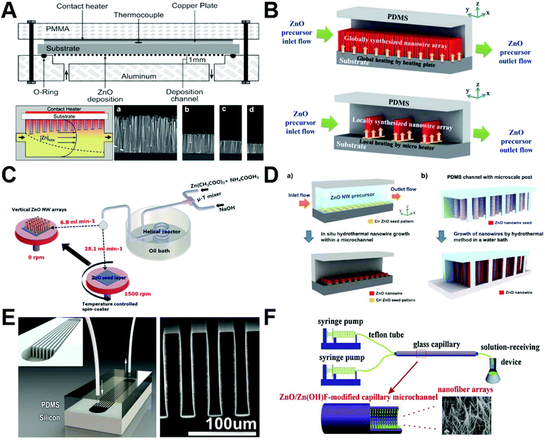 |
| | Fig. 2 Continuous laminar flow microreactors for the synthesis of wire/rod-like ZnO materials. (A) ZnO nanowires grown by chemical bath deposition in a continuous flow microreactor (a, b, c, and d show SEM images taken at positions downstream from the inlet). Reproduced with permission from ref. 48, copyright 2009, American Chemical Society. (B) Schematics of in situ synthesis and integration of ZnO nanowires in a microfluidic chip: (top) global synthesis in the entire fluidic channel and (bottom) local synthesis with microheaters in the fluidic channel. Reproduced with permission from ref. 53, copyright 2011, Royal Society of Chemistry. (C) Schematic diagram showing the growth of the seed layer and vertical ZnO nanowire arrays using the microreactor-assisted nanoparticle deposition system. Reproduced with permission from ref. 68, copyright 2016, Royal Society of Chemistry. (D) Schematic diagram of (a) patterned growth of ZnO nanowire arrays by an in situ synthesis method and (b) growth of ZnO nanowires on microstructure arrays by a conventional hydrothermal method. Reproduced with permission from ref. 54, copyright 2012, Royal Society of Chemistry. (E) Microfluidic hydrothermal growth of ZnO nanowires over high aspect ratio microstructures. Reproduced with permission from ref. 58, copyright 2013, IOP Publishing, Ltd. (F) Schematic diagram of the synthesis of the ZnO/Zn(OH)F nanofiber array constructed on the inner wall of the capillary microchannel. Reproduced with permission from ref. 73, copyright 2016, Elsevier. | |
3.1.2. Sphere.
Since the feasibility of microfluidic flow synthesis of ZnO nanospheres was first demonstrated in 2004,46 an increasing number of laminar flow synthesis approaches with distinct microreactor structures have been developed (Fig. 3). Based on the supercritical coflowing microreactor, UV emitting ZnO spheres (∼4 nm in diameter) with pure excitonic photoluminescence were continuously formed (Fig. 3A), and the combined use of coaxial injection and H2O2 addition successfully addressed the clogging limitations encountered in most microfluidic applications for chemical engineering.51 Preparation of small-sized ZnO nanoparticles (7–26 nm) was also realized in a membrane dispersion microreactor (Fig. 3B), where the use of NH4HCO3 fluid can generate CO2 bubbles by the released heat from two-flow collision and precipitation processes for further intensifying the mass transfer and reducing aggregation.56 Through implementing a time pulsed mixing method (Fig. 3C), the microreactor was demonstrated to produce ZnO nanospheres with similar particle size (3–5 nm) and crystalline structure to the batch reactor.64 In addition, an ultrasonic microreactor was also employed to synthesize green emission ZnO quantum dots with an average size of 2.4 nm (Fig. 3D). The flow rate, ultrasonic power, and temperature significantly affected the type and quantity of defects in ZnO products.70 These results demonstrate that ZnO spheres can be continuously synthesized from laminar flow microreactors or more complicated integrated microfluidic systems. However, the available particle sizes in these approaches were only in a narrow range from several to a few tens of nanometers.
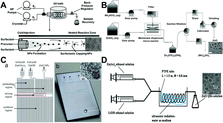 |
| | Fig. 3 Continuous laminar flow microreactors for the synthesis of sphere-like ZnO materials. (A) Synthesis of exciton luminescent ZnO nanocrystals using continuous supercritical microfluidics. Reproduced with permission from ref. 51, copyright 2011, John Wiley & Sons. (B) Preparation of small-sized ZnO nanoparticles in a membrane dispersion microreactor. Reproduced with permission from ref. 56, copyright 2013, American Chemical Society. (C) Schematic diagram (a) and photograph (b) of the microfluidic channel with time pulsed mixing used for ZnO nanoparticles synthesis. Reproduced with permission from ref. 64, copyright 2014, Royal Society of Chemistry. (D) Synthesis of high quantum yield ZnO quantum dots via an ultrasonication microreactor method. Reproduced with permission from ref. 70, copyright 2016, Elsevier. | |
3.1.3. Flower.
Continuous synthesis of ZnO flowers was generally carried out in laminar flow microreactors with a T-shaped mixer (Fig. 4A).47,59,63 The flower structures can be formed either on oxidized silicon substrates47,63 or in the solution base.59 In the former approach, the size of ZnO flowers was found to increase with the increase in the treatment time and temperature, and the structure of flowers was affected under different flow rates or concentrations of NaOH.47,63 The latter solution growth approach not only allows controllable synthesis of ZnO flowers but also permits easy dopant addition. The resultant metal-doped ZnO flower structures exhibit much enhanced performance as a result of increased surface defect sites associated with oxygen when metals replace Zn in the crystal structure.59 In addition to the conventional glass capillary or PDMS microreactor, a cellulose hydrogel with a rich porous texture was also successfully employed as a microreactor platform to synthesize ZnO flowers with relatively uniform particle size (Fig. 4B).74 These results validate the applicability of microfluidic reactors (even in a bioresource form) in the controllable synthesis of flower-like structures, providing new insights for the development of hierarchical ZnO products.
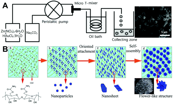 |
| | Fig. 4 Continuous laminar flow microreactors for the synthesis of flower-like ZnO materials. (A) Schematic diagram of a T-shaped micromixer reactor system for the synthesis of ZnO microflowers. Reproduced with permission from ref. 59, copyright 2013, Royal Society of Chemistry. (B) Preparation of flower-like ZnO nanoparticles in a cellulose hydrogel microreactor. Reproduced with permission from ref. 74, copyright 2017, North Carolina University. | |
3.1.4. Sheet/flake.
Microfluidic synthesis of ZnO sheet/flake nanostructures can be realized by two similar approaches as mentioned above: in situ growth approach and ex situ generation approach (Fig. 5). The microfluidic in situ growth approach not only permits oriented aligned nanosheets on the desired surface areas without any extra assembly process, but also allows additive reactants to be directly delivered to the pre-seeded reaction area with no or low reagent consumption (Fig. 5A).66 However, such an approach only results in a localized reaction at the desired surface area, which limits the large scale fabrication of ZnO nanosheets. Comparatively, based on the serpentine and spiral microchannels (Fig. 5B), ZnO nanosheets can be continuously collected from the outlet of microreactors at appropriate flow rates of zinc nitrate and sodium hydroxide fluids.75,82 However, it is difficult for this ex situ generation approach to provide aligned nanostructures in specific directions. Therefore, both approaches still face the challenge of grappling with the gap between the controllable growth process and materials quality of ZnO sheets/flakes.
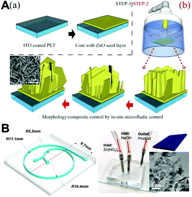 |
| | Fig. 5 Continuous laminar flow microreactors for the synthesis of sheet-like ZnO materials. (A) Illustration of the strategy for fabrication of controllable Al-doped ZnO (AZO) nanostructures: (a) step 1 for pre-seed substrates; (b) step 2 for the in situ hydrothermal method used for controllable AZO synthesis. Reproduced with permission from ref. 66, copyright 2015, Springer Nature. (B) Spiral-shaped laminar flow microreactor for the synthesis of ZnO nanosheets. Reproduced with permission from ref. 82, copyright 2019, Elsevier. | |
3.1.5. Spindle/ellipsoid.
Continuous laminar flow synthesis of spindle/ellipsoid-like ZnO materials can be generally achieved by either a self-assembly strategy55,75,82 or a seed-mediated growth strategy.69 A microfluidic reaction system could not only facilitate the homogeneous nucleation and growth of ZnO nanocrystals by minimizing the temperature and pH gradient in the solution, but also enable us to tailor the crystal growth process by simply changing the operation parameters (such as the flow rate and residence time). Relying on the Dean vortices in a winding microcapillary tube, ZnO spindles were successfully formed by the assembly of nanocrystals at an appropriate Dean number of 78 (Fig. 6A), whereas non-assembled and spherical ZnO products were formed at Dean numbers of 36 and 150, respectively.55 Similarly, PDMS-based serpentine (Fig. 6B) and spiral microchannels were also demonstrated to assemble spindles from ZnO nanocrystals but only at specific flow rates of reactant fluids.75,82 In addition to the self-assembly strategy, the seed-mediated growth strategy was also developed for the flow synthesis of ZnO spindles in a continuous two-stage microfluidic system (Fig. 6C). Monodisperse triangular silver nanoparticles were firstly formed in a T-mixer and a spiral microreactor, and then directly fed into a cross-type mixer as seeds for the controllable growth of ZnO spindles on a silver particle surface to form a final hedgehog-like Ag–ZnO structure.69 These results demonstrate the feasibility of laminar flow microreactors in the synthesis of ZnO spindles; however, further studies that enable precise control of the size dimensions of spindle/ellipsoid structures are necessary.
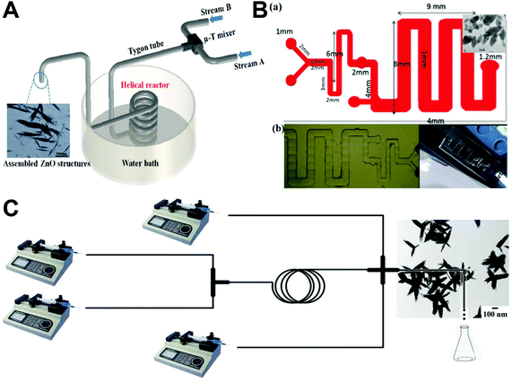 |
| | Fig. 6 Continuous laminar flow microreactors for the synthesis of spindle-like ZnO materials. (A) Schematic diagram of the growth and assembly of ZnO tactoids in a continuous flow microreactor. Reproduced with permission from ref. 55, copyright 2013, Royal Society of Chemistry. (B) PDMS-based microreactor for the synthesis of ZnO spindles. Reproduced with permission from ref. 75, copyright 2017, IOP Publishing, Ltd. (C) Experimental setup used for the continuous preparation of Ag–ZnO nanohedgehogs. Reproduced with permission from ref. 69, copyright 2016, Royal Society of Chemistry. | |
3.2. Discrete segmented flow synthesis
Compared to continuous laminar flow microreactors, discrete segmented flow microreactors have received very little attention from researchers for the synthesis of ZnO micro-/nanoparticles (Table 1). The reported discrete microreactor studies are mainly focused on the liquid–liquid segmented flow that generates droplets as water-in-oil emulsions (Fig. 7).52,62,77 The resultant droplets can serve as excellent reactors to carry out chemical reactions and form high quality ZnO products because of intensive mixing efficacy, consistent residence time, and efficient heat/mass transfer afforded by each droplet. T-junction (Fig. 7A) and flow-focusing microfluidic devices (Fig. 7C) are usually designed to enable the droplet generation of the reaction mixture in a continuous phase fluid.52,77 In addition, droplet synthesis of ZnO materials could be also realized from microemulsions in a continuous flow microreactor (Fig. 7B).62 Many parameters can regulate the formation of the droplets, such as the flow rate, solution viscosity, and microchannel geometry, which in turn affect the size and shape of ZnO particles. Liquid–gas segmented flow for the synthesis of ZnO particles has rarely been reported. One feasible method is to apply NH4HCO3 as reactant flow for the generation of CO2 bubbles resulting from two-flow collision and precipitation processes in the reaction microchannel (Fig. 3B),56 and the other method is to integrate ultrasonic radiation with the microreactor for bringing bubbles through ultrasonic cavitation (Fig. 3D).70 By choosing adequate precursors and reactant concentrations, sphere-, rod-, star-, and flower-shaped ZnO micro-/nanoparticles could be continuously produced from discrete flow microreactors,52,62,77 and the particle sizes show more narrow distribution than those from a batch reactor.62 These preliminary results pave the way for exploring more rational design of discrete segmented flow microreactors in the controllable synthesis of ZnO materials.
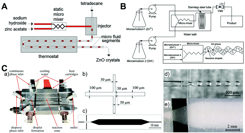 |
| | Fig. 7 Discrete segmented flow microreactors for the synthesis of ZnO materials. (A) Experimental setup for hydrothermal continuous-flow synthesis of sphere-, cylinder-, star- and flower-like ZnO microparticles. Reproduced with permission from ref. 52, copyright 2011, Elsevier. (B) Schematic diagram of the flow synthesis of nanoparticles using microemulsions in a microreactor. Reproduced with permission from ref. 62, copyright 2014, Elsevier. (C) Microfluidic droplet synthesis of ZnO nanoparticles: (a) photograph of a microfluidic chip; (b) flow-focusing geometry; (c) microfluidic design with and expansion channel in the heated reaction zone; (d) droplet formation of the precursor and benzyl alcohol in Fluoronox; and (e) stable and monodisperse droplets in the reaction zone of the device. Reproduced with permission from ref. 77, copyright 2018, Elsevier. | |
4. Microfluidic applications of ZnO materials
In the past decade, microfluidic chips have demonstrated their great potential in enabling micro-total analysis systems and integrating multiplexed functional units into a single device. Given their advanced features such as high system integration, low sample consumption, fast response, good reproducibility, and high reliability, microfluidic chips have become attractive tools for many potential applications (Table 2). In this section, we will highlight the unprecedented opportunities of microchips in advancing applications of electrochemical sensing, immunofluorescence sensing, SERS sensing, biological separation, and molecular catalysis.
Table 2 Applications of ZnO materials through microfluidic chips
| Microchip type |
Material type |
Materials properties |
Application |
Target/efficacy |
Ref. (by year) |
| Abbreviations: AFP: α-fetoprotein; CEA: carcinoembryonic antigen; CTCs: circulating tumor cells; DME: dimethyl ether; MB: methylene blue; MO: methyl orange; MP: methylparathion; PAA: poly(acrylic acid); PAD: paper-based analytical device; PP: phosphopeptide; PVA: polyvinyl alcohol; rGO: reduced graphene oxide; RT: residence time; SAW: surface acoustic wave; and SERS: surface-enhanced Raman scattering. |
| Micropump |
ZnO |
Film (<6.6 μm thick) |
SAW |
1 cm s−1 velocity |
200983 |
| Capillary microchannel |
ZnO/TiO2 |
Nanowire array (1.5 μm thick) |
Photocatalysis |
100% MB (RT = 20 s); >90% (after using for 100 h) |
201050 |
| Capillary microchannel |
ZnO/TiO2 |
Nanowire array (1.5 μm thick) |
PP enrichment |
50 fmol; 5 cycles |
201184 |
| Straight microchannel |
ZnO |
Nanowire array (5–6 μm thick) |
Particle trapping; pH sensing |
10 μm particle trapping; pH: 5–9 |
201153 |
| Straight microchannel |
ZnO |
Nanowire array (2–3 μm thick) |
Cell lysis |
Increased protein and nucleic acid concentration |
201254 |
| Capillary microchannel |
ZnO/Pt |
Nanowire array (1–2 μm thick) |
Photocatalysis |
93% phenol (RT = 180 s); >85% (after using for 110 h) |
201385 |
| Microchamber |
ZnO |
Nanowire array (20 μm thick) |
Photocatalysis |
96% MB (RT = 270 s) |
201360 |
| Micropump |
ZnO |
Film (<6–8 μm thick) |
SAW |
0.1–90 mm s−1 velocity |
201386 |
| Straight microchannel |
ZnO |
Nanowire array (4 μm thick) |
Photovoltaic cells |
Low reflection rates |
201357 |
| Microchamber |
ZnO–Ag |
Nanowire array (1–1.5 μm thick) |
Cell trapping; SERS sensing |
HeLa cells; 4-ATP; BSA (0.01%); DNA (1 μM) |
201461 |
| T-type microchannel |
ZnO |
Nanosphere array (∼20 nm) |
Electrochemical immunosensing |
Thyrotropin (0.00087 μUI mL−1) |
201487 |
| Straight microchannel |
ZnO–PVA |
Nanofilm (200 nm thick) |
Fluorescence sensing |
SYTO 13 dye (1 μM) |
201488 |
| Micropump |
ZnO |
Film (5.5 μm thick) |
SAW |
1500 m s−1 velocity |
201489 |
| Micropump |
ZnO |
Film (4 μm thick) |
SAW |
10 cm s−1 velocity |
201490 |
| Straight microchannel |
CuO–ZnO–Al2O3/HZSM-5 |
Film (20–60 μm thick) |
Catalyst |
CO conversion; DME production |
201591 |
| PAD |
ZnO |
Nanowire array (∼300 nm width) |
Electrochemical sensing |
Glucose (94.7 μM) |
201592 |
| Straight microchannel |
ZnO–CuO |
Nanowire array (3 μm thick) |
Electrochemical sensing |
NO2 (0.1–20 ppm); CO (20–1000 ppm) |
201565 |
| Microchamber |
ZnO![[thin space (1/6-em)]](https://www.rsc.org/images/entities/char_2009.gif) : :![[thin space (1/6-em)]](https://www.rsc.org/images/entities/char_2009.gif) Al Al |
Nanoflake layer (6 μm thick) |
Dye-sensitized solar cells |
410% enhancement compared to pure ZnO |
201566 |
| Microchamber |
ZnO@ZnS–Ag |
Nanowire array (1–2 μm thick) |
SERS sensing |
R6G (10−9 M); 4-MBA (10−9 M); MP (10−8 M); BSA (10−8 M) |
201667 |
| PAD |
ZnO |
Nanowire array (4.37 μm thick) |
Electrochemical sensing |
IgG (60 fg mL−1); p24 antigen (300 fg mL−1) |
201693 |
| Straight microchannel |
ZnO |
Nanowire array (1–2 μm thick) with sharp end or hexahedral-puncheon |
Immunofluorescence sensing |
Streptavidin (417 fM); IgG (4.17 pM) |
201671 |
| Microchamber |
ZnO |
Nanowire array (1–3 μm thick) |
Electrochemical immunosensing |
1 pg mL−1 H1N1; H5N1; H7N9 |
201672 |
| Straight microchannel |
ZnO/Zn(OH)F |
Nanowire array (40 μm thick) |
Photocatalysis; protein separation |
96% MB (RT = 60 s); ∼100% hemoglobin (RT = 60 s) |
201673 |
| Straight microchannel |
ZnO |
Film (120 nm thick) |
pH sensing (CTCs detection) |
pH: 1.68–9.18 |
201794 |
| Straight microchannel |
ZnO |
Nanowire array (1–4 μm thick) |
Photocatalysis |
97% MO (RT = 60 s) |
201776 |
| Wedge-shaped chip |
ZnO |
Nanowire array (2 μm thick) |
CTCs detection |
>87.5% SKBR3; PC3; HepG2; A549 |
201795 |
| Herringbone chip |
ZnO |
Nanowire array |
Immunofluorescence sensing |
H5N2 (3.6 × 10³ EID50 mL−1) |
201796 |
| Straight microchannel |
ZnO |
Nanowire array (∼10 μm thick) |
Immunofluorescence sensing |
AFP (1 pg mL−1); CEA (100 fg mL−1) |
201878 |
| PAD |
ZnO–rGO |
Nanoflower array (∼50 μm thick) |
Electrochemical sensing |
L-Glutamic acid (9.6 pM); L-cysteine (24 pM) |
201897 |
| Microchamber |
ZnO |
Nanowire array (9.14 μm thick) |
Electrochemical sensing |
Erythrocytes; leukocytes |
201898 |
| Microchamber |
ZnO |
Nanowire array (∼1 μm thick) |
Photocatalysis |
10 ppm benzene; toluene; ethylbenzene; m–p xylenes; o-xylene |
201879 |
| Straight microchannel |
ZnO–PAA |
Nanowire array (500 nm thick) |
Immunofluorescence sensing |
CEA (100 fg mL−1) |
201880 |
| Fixed-bed reactor |
ZnO–CuO |
0.1 g catalyst (40–60 mesh) |
Catalyst |
∼1–6 g MeOH per gram catalyst per hour |
201981 |
4.1. Electrochemical sensing
ZnO materials show fast electron transfer and a high isoelectric point of 9.5 and can be electrostatically bonded to negatively charged matter at the physiological pH, while microfluidics enables high integration, fast response, and low sample consumption. These features make microfluidics-ZnO a promising platform for electrochemical sensing of targets such as pH,53,94 biomolecules,72,87,92,93,97 gas molecules,65 and blood.94,98 Since ZnO is an n-type semiconductor whose surface electron charge could be changed by the surrounding ion charge concentration, this change of surface charge causes electrical conductance modulation at different pH levels and thus allows for pH sensing. It was found that, due to the formation of a depletion layer at the surface, the conductance of the ZnO nanowire array decreases as the pH level is increased.53 Considering the slightly acidic extracellular environment of cancer cells at pH 6.2–6.9 compared to 7.3–7.4 of normal cells, a highly sensitive and stable microfluidic pH sensor was developed for successful identification of circulating tumor cells based on the precise pH measurements between the ZnO working electrode and Ag/AgCl reference electrode (Fig. 8A).94 The integration of ZnO nanowires with a microfluidic chip was also employed to measure the impedimetric ratio of erythrocytes to leukocytes for monitoring a patient's disease activity (Fig. 8B).98 In addition, based on programmable temperature control and parallel chemical supply within a microfluidic platform, heterogeneous nanomaterial arrays containing ZnO were developed as multiplexed gas sensors for sub-ppm NO2 and tens of ppm CO gas detection.65 Similarly, ZnO-based PDMS and paper microfluidic chips have been widely applied for the sensing detection of various biomolecules, such as thyrotropin,87 glucose,92 IgG,93 HIV p24 antigen,93 amino acids (L-glutamic acid and L-cysteine),97 and influenza viruses (H1N1, H5N1, and H7N9).72 Specifically, the PDMS microfluidic chip for electrochemical sensing of biomolecules generally involves both an immobilized capture antibody and a horseradish peroxidase (HRP)-conjugated detection antibody to generate a signal. HRP enables oxidation of its enzymatic substrate (such as 3,3′,5,5′-tetramethylbenzidine72 and 4-tert-butylcatechol87), resulting in changes of both the optical color of the solution containing the substrate and electrochemical redox current (Fig. 8C). Comparatively, a microfluidic paper-based analytical device (μPAD) integrated with ZnO materials represents a promising platform for label-free and ultrasensitive electrochemical detection due to its low cost, high portability, and ease of operation,92,93,97 especially the unnecessary use of a light-sensitive electron mediator for enhancing biosensing stability (Fig. 8D). Among different types of ZnO materials, it is interesting to point out that a flower-shaped nanostructure shows superior electrochemical signals compared to nanosphere, nanosheet, and nanorod arrays, revealing the importance of structural design when applying nanoparticles for biomedical applications.99–103
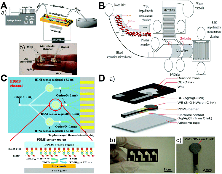 |
| | Fig. 8 Microfluidics-enabled electrochemical sensing applications of ZnO materials. (A) Experimental scheme (a) and photograph (b) of a ZnO-based microfluidic pH sensor. Reproduced with permission from ref. 94, copyright 2017, American Chemical Society. (B) Measurement of the impedimetric ratio of blood cells using the microfluidic chip with ZnO nanowires. Reproduced with permission from ref. 98, copyright 2018, Springer Nature. (C) A multi-virus detectable microfluidic electrochemical immunosensor for simultaneous detection of H1N1, H5N1, and H7N9 viruses using ZnO nanorods for sensitivity enhancement. Reproduced with permission from ref. 72, copyright 2016, Elsevier. (D) A paper-based microfluidic biosensor integrating zinc oxide nanowires for electrochemical glucose detection. Reproduced with permission from ref. 92, copyright 2015, Springer Nature. | |
4.2. Immunofluorescence sensing
Due to their high specificity and sensitivity, immunofluorescence assays have been widely used in the sensing detection of biomolecules. Considering the low sample consumption feature from microfluidics and the desirable optical feature of a wide band gap (3.37 eV) and a large excitation binding energy (60 meV) from ZnO nanostructures, the integration of ZnO with microfluidics showed remarkable capability to improve the sensing performance of immunofluorescence assays. Almost all established immunofluorescence sensing studies utilized densely packed ZnO rods/wires with large surface-to-volume ratios and aspect ratios for greatly enhancing the fluorescence intensity.71,78,80,88,96 Owing to their high transmittance and intrinsically enclosed microchannel, glass capillaries served as an ideal substrate for immunofluorescence sensing. When introducing polyacrylic acid (PAA) as a hydrophilic layer for increasing the antibody loading capacity and reducing nonspecific protein adsorption, the resultant ZnO–PAA nanorod arrays constructed on the inner wall of glass capillaries can detect the concentration of the carcinoembryonic antigen (CEA) as low as 100 fg mL−1 (Fig. 9A).80 Besides glass capillaries, PDMS-based microfluidic chips have also been widely utilized for the immunofluorescence multiplex detection of proteins and viruses.71,78,96 ZnO nanowire-integrated microchannels can significantly decrease the detection limit to 1 pg mL−1 for α-fetoprotein (AFP) assay and 100 fg mL−1 for CEA assay (Fig. 9B).78 The particle shape has been revealed to affect the biological performance of nanomaterials,104,105 and it was also demonstrated to play significant roles in the immunofluorescence sensing detection of ZnO materials. Compared to rod nanowires and hexahedral-puncheon nanostructures, sharp ZnO nanowires exhibit the largest dynamic range and the highest fluorescence intensity.71 When using the sharp nanowires for simultaneous anti-mouse IgG and anti-rabbit IgG detection, fluorescence images present clear multiple detection at the crossover areas (Fig. 9C). In addition, the ZnO nanorod array-integrated microfluidic chip can act as a multiplex immunofluorescent platform for highly selective and sensitive detection of avian influenza virus (AIV).96 The unique optical properties and 3D morphology of nanorod arrays allowed the detection limit of H5N2 AIV to be as low as 3.6 × 10³ EID50 mL−1, which is around 22 times more sensitive than conventional enzyme-linked immunosorbent assays (Fig. 9D). However, it is noted that native PDMS surfaces are hydrophobic and may adsorb small dye molecules, which may limit the applicability of PDMS in immunofluorescence analysis.88
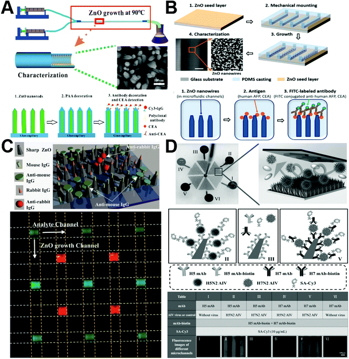 |
| | Fig. 9 Microfluidics-enabled immunofluorescence sensing applications of ZnO materials. (A) Enhanced immunofluorescence detection of a protein marker using a PAA modified ZnO nanorod array-based microfluidic device. Reproduced with permission from ref. 80, copyright 2018, Royal Society of Chemistry. (B) Enhanced fluorescence detection of proteins using ZnO nanowires integrated inside microfluidic chips. Reproduced with permission from ref. 78, copyright 2018, Elsevier. (C) Multiple detection of anti-mouse IgG and anti-rabbit IgG using sharp ZnO NWs (a) and fluorescence image of simultaneous multiple protein detection with the microfluidic device (b). Reproduced with permission from ref. 71, copyright 2016, Elsevier. (D) Multiplexed detection of two AIV subtypes of H5N2 and H7N2 in one ZnO nanorod integrated microchip. Reproduced with permission from ref. 96, copyright 2017, John Wiley & Sons. | |
4.3. SERS sensing
Label-free sensing detection of analytes from small volume, highly diluted, and multicomponent samples is vitally important in diverse fields. The surface-enhanced Raman scattering (SERS) technique allows direct, sensitive, nondestructive, and real-time recording of quantitative chemical information, while the microfluidic technique permits controllable manipulation of small volumes of fluids. Therefore, the use of integrated microfluidics-SERS platform represents a promising approach for label-free analysis of a small amount of analytes. In recent years, ZnO-based 3D nanostructured materials grown in microchannels have demonstrated to be effective in facilitating SERS detection of many analytes, such as proteins, nucleic acids, dyes, and cells (Fig. 10).61,67 By microfluidic in situ deposition of Ag nanoparticles on the vertically aligned ZnO nanorods, the resultant Ag@ZnO as a SERS substrate was able to detect 1 μM DNA and the surface chemical fingerprint of a single living cell could be recorded (Fig. 10A).61 In addition, glass capillary-based SERS microanalysis platforms were also developed because of their appealing features such as low cost, facile fabrication and operation, and special capillary forces that can readily drive the fluid flowing into a capillary. Using the afforded ZnO@ZnS–Ag clustered nanorod arrays on the inner wall of capillary microchannels, high SERS sensitivity of 4-mercaptobenzoic acid (4-MBA, 10−9 M), rhodamine 6G (R6G, 10−9 M), and methyl parathion (MP, 10−8 M) was achieved (Fig. 10B).67 Considering its simplicity, controllability, sensitivity, and versatility, the ZnO-based microfluidics-SERS platform should be valuable in many biomedical and environmental applications.
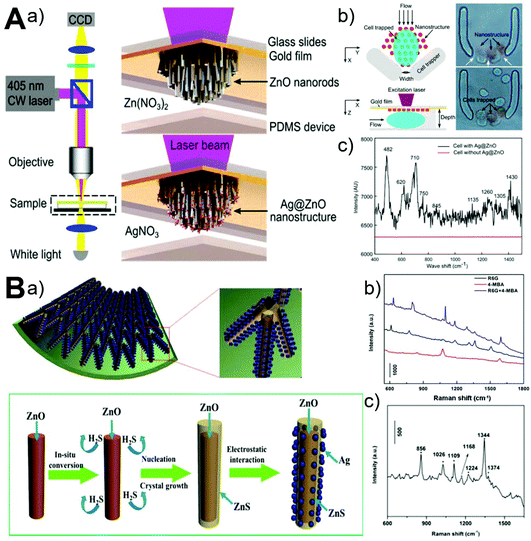 |
| | Fig. 10 Microfluidics-enabled SERS sensing applications of ZnO materials. (A) Microfluidic in situ fabrication of 3D Ag@ZnO nanostructures (a) and SERS fingerprinting of trapped single cells (b and c). Reproduced with permission from ref. 61, copyright 2014, American Chemical Society. (B) Microfluidic capillary synthesis of 3D clustered ZnO@ZnS–Ag nanostructures (a) and SERS sensing performance of R6G, 4-MBA, and MP (b and c). Reproduced with permission from ref. 67, copyright 2016, American Chemical Society. | |
4.4. Biological separation
Owing to its unique advantage of miniaturization and integration, microfluidics has drawn more and more attention in the field of biological separation. The integration of microfluidics with zinc oxide materials has successfully demonstrated its superior capabilities in the highly efficient enrichment of proteins73,84 and cells.95 Based on the coordination affinity of zinc to histidine, confined ZnO/Zn(OH)F nanowire arrays inside capillary microchannels could adsorb all the bovine hemoglobin (0.5 mg mL−1) at a residence time of 50 s and isolate human hemoglobin from human blood (500-fold diluted) effectively due to the high contact area afforded by 3D ZnO nanostructures.73 Since phosphate functional groups can bind to the surface of metal oxide particles, TiO2-immobilized ZnO nanorod arrays were also aligned on the inner wall of the capillary microchannel for phosphopeptide enrichment from tryptic protein digests with great selectivity, sensitivity, and durability (Fig. 11A).84 In addition, to achieve highly efficient isolation and gentle release of circulating tumor cells, a microfluidic chip containing a wedge-shaped microchannel with a gradually decreasing height and a layer of a ZnO nanorod substrate was developed (Fig. 11B). By integrating size-dependent filtration with a degradable nanostructured substrate, a capture efficiency over 87.5% was achieved and up to 85.6% of the captured cells were easily released after reverse injection of diluted phosphoric acid to dissolve the ZnO substrate.95 Given their superior features, microfluidics-integrated ZnO materials may find greater success in the separation of a large variety of biomolecules and cells.
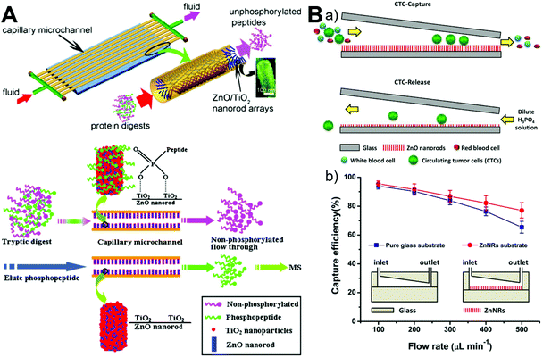 |
| | Fig. 11 Microfluidics-enabled biological separation applications of ZnO materials. (A) Continuous high-throughput phosphopeptide enrichment using microfluidic channels modified with aligned ZnO/TiO2 nanorod arrays. Reproduced with permission from ref. 84, copyright 2011, Springer Nature. (B) Highly efficient isolation and release of circulating tumor cells based on size-dependent filtration and a degradable ZnO nanorod substrate in a wedge-shaped microfluidic chip (a), and capture efficiency of spiked SKBR3 cells at different flow rates in two kinds of microfluidic chips with/without a ZnO nanorod substrate (b). Reproduced with permission from ref. 95, copyright 2017, Springer Nature. | |
4.5. Molecular catalysis
Microfluidic chips have attracted great attention for catalytic applications due to their inherently large surface-to-volume ratios, short diffusion distance, rapid mass transfer, and high integration capabilities. By easy interfacing with UV light, microchips find great application in photocatalysis for the photodegradation of methylene blue (MB),50,60,73 phenol,85 methyl orange,76 and volatile organic compounds (benzene, toluene, ethylbenzene, m–p xylenes, and o-xylene).79 ZnO nanowires have a high electron transfer rate and could be grown on a patterned area over a glass substrate60,76 (Fig. 12A) or Si substrate79 (Fig. 12B), allowing easy integration into chamber-based microfluidic chips.60,76,79 Besides microchambers, ZnO wire/rod arrays could be also patterned on the inner wall of glass capillary-based microfluidic chips for continuous flow photocatalysis (Fig. 12C and D).50,73,85 Given that one of the major issues for ZnO photocatalysts is the lower photocatalytic efficiency due to quick combination of photoinduced charge carriers, many heterostructures, such as TiO2-coated ZnO rod arrays50 (Fig. 12C) and Pt-coated ZnO rod arrays85 (Fig. 12D), were developed inside the capillary microchannel. These kinds of hetero-photocatalysts not only suppressed the recombination of photogenerated electron–hole pairs, but also extended the light adsorption spectrum and thus improved the light use efficiency.50,85 It is noted that, in addition to photocatalysis, microfluidic chips with integrated ZnO-based hetero-catalysts also exhibit superior performance in the direct conversion of syngas to dimethyl ether and methanol.81,91 These results clearly reflect the robust applicability of microfluidic-ZnO as a catalytic system, especially in the photocatalysis field. Although considerable progress has been achieved, the greatest challenge facing microfluidic chips is the throughput when applying ZnO catalysts into practical industrial settings.
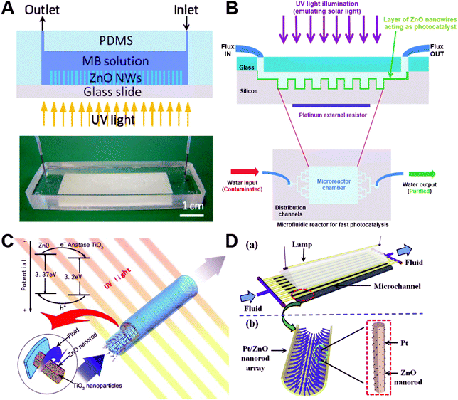 |
| | Fig. 12 Microfluidics-enabled catalytic applications of ZnO materials. (A) Microfluidic device with integrated ZnO nanowires for photodegradation of MB. Reproduced with permission from ref. 60, copyright 2013, Elsevier. (B) Schematic illustration of the experimental setup used for water decontamination. The microfluidic reaction chamber including ZnO nanowires acting as a photocatalyst is exposed to ultraviolet (UV) light while water is flowing, leading to purified water at the outlet. Reproduced with permission from ref. 79, copyright 2018, Springer Nature. (C) Capillary microchannel-based microreactors with highly durable ZnO/TiO2 nanorod arrays for continuous-flow photocatalysis of MB. Reproduced with permission from ref. 50, copyright 2010, Elsevier. (D) Microreactor with Pt/ZnO nanorod arrays on the inner wall for photodegradation of phenol. Reproduced with permission from ref. 85, copyright 2013, Elsevier. | |
Besides the bioapplication areas discussed above, ZnO materials also enable some other promising applications established with microfluidic systems. ZnO thin film-based surface acoustic wave (SAW) devices have been successfully utilized to fabricate microfluidic pumps.83,86,89,90 Among different deposition substrates (Si, glass, and polyimides), ZnO deposited on a Si substrate exhibits the highest acoustic streaming velocity of about 10 cm s−1 and the shortest particle concentration time of less than 10 seconds.90 When introducing ultra-smooth nanocrystalline diamond films with high-acoustic wave velocity as an interlayer into a ZnO-based SAW device, the microfluidic efficiency was found to be further enhanced due to reduced acoustic energy dissipation into the Si substrate and improved acoustic properties of SAW devices.86 In addition, by patterning ZnO nanowire arrays as special U-shaped microcages, microparticles were trapped while the dispersion media continuously flowed out through the porous network of nanowires, revealing their great potential as single cell capture structures.53 Another interesting application is for facile and high-throughput mechanical cell lysis by virtue of the sharp ends of high aspect ratios of nanowires. The microfluidic chip integrated with a patterned ZnO nanowire array was demonstrated to successfully tear the plasma membrane, and is even more effective than conventional chemical lysis methods but with a shorter processing time and simpler equipment.54 Furthermore, due to their superior features such as ease of synthesis, low cost, wide bandgaps, high bulk electron mobility, appropriate refractive index, and flexible morphology control, ZnO nanostructures have already demonstrated their great potential in energy-harvesting devices.57,66
5. Current challenges and future perspectives
The past decade has witnessed considerable progress in the development of microfluidic systems for controllable synthesis and applications of ZnO micro-/nanomaterials. Owing to their many unique and attractive features (especially flexible spatio-temporal control, high integration capability, and low sample consumption),106–113 microfluidic devices fabricated with PDMS or glass capillaries significantly advance the rational design and applicability of functional materials. To date, ZnO structures with different sizes, shapes, and compositions have been developed for applications in the biomedical fields. However, many challenges still remain to be addressed before the full potential of microfluidics can be realized.
From the materials synthesis aspect, (1) compared to conventional batch reactors, microfluidic reactors provide new and alternative opportunities for controllable synthesis of ZnO materials. However, only very few studies revealed the unique merits of microreactors by direct comparison to batch reactors under the same reaction conditions.49,63,64,68 More parallel studies are greatly needed to demonstrate the advanced features of microfluidics for ZnO production in terms of faster reaction kinetics, higher reproducibility, and better physicochemical properties. (2) There is still a lack of inline management control over the flow synthesis process. Full exploitation of microfluidic systems requires real-time information about the chemical reaction progress for realizing an immediate response in the optimization of structural properties. Although microreactors permit high integration and automation, inline control systems for ZnO materials synthesis are still rarely reported. (3) Despite ZnO materials with different sizes (from a few nanometers to tens of micrometers), shapes (wire/rod, sphere, flower, sheet/flake, and spindle/ellipsoid), and compositions (such as metal-doped, polymer-modified, and functional nanoparticles-coated) being already available from microreactors, there is still relatively low structural diversity. As shown in Table 1, most ZnO particles are sizes less than ten nanometers or larger than submicrometers, mainly wire/rod and sphere shapes, and show a lack of variability in hierarchical compositions. To meet the needs of diverse applications, ZnO materials with rich structural diversity should be systematically developed. (4) Due to small dimensions and low operation volumes of microreactors, the production amount of ZnO materials can only reach up to grams per day.82 To further improve the yields, more robust and integrated design of microreactors with parallel multiple modules should be established for scale-up production of ZnO materials.
From the materials application aspect, (1) given the unique advantages of microfluidic chips, plenty of studies on the integration of ZnO materials with microfluidics have been carried out and significant progress has been achieved in the areas of biosensing, biological separation, and molecular catalysis (Table 2). Though many ZnO-based PDMS and glass capillary microfluidic devices have been developed and they exhibited good performance, the applications of ZnO materials in microfluidic chips are still an urgent need for being optimized and improved.73 (2) Almost all the established microfluidic application systems relied on the nanowire or nanorod array of ZnO materials, and comparatively, very little attention has been paid towards exploration of other structures. Although it can be easily understood that the in situ deposited wire/rod array inside a microchannel provides great convenience for subsequent analysis and application, the structural properties of ZnO materials should be systematically investigated to fully reveal their potential use. (3) The effect of particle structures (such as particle size and shape) on the application performance of ZnO materials is still rarely examined in microfluidic systems.82,97 Since a large number of studies have already shown that the particle structures of micro-/nanomaterials significantly regulate their downstream application efficacy,114–117 more attention should be paid to maximizing the potential of ZnO materials. (4) Most of the ZnO-integrated microfluidic application systems are still in the proof-of-concept stage. Compared to conventional batch operation systems, microfluidic chips have demonstrated superior performance in sensing sensitivity, separation capability, and catalysis efficiency. However, one of the biggest challenges facing microfluidic application systems is finding ways to improve the throughput while maintaining the same efficient performance inside miniaturized devices. Therefore, there is still a long way to go from laboratory benches to practical implementation in industrial settings.
6. Conclusion
This review provides a comprehensive summary of recent advances in microfluidics-enabled rational design, controllable synthesis and on-chip applications of ZnO micro-/nanomaterials. We discussed the flow synthesis approaches of ZnO materials with different structures (wire, rod, sphere, flower, sheet, flake, spindle, and ellipsoid) using continuous laminar flow microreactors and discrete segmented flow microreactors, and highlighted the unprecedented opportunities for applying ZnO-integrated microchips in biosensing, biological separation, and molecular catalysis applications, and finally pointed out the major challenges and opportunities for inspiring future studies in this area. Despite great achievement in a relatively short period, microfluidics is still a less exploited tool in the synthesis and applications of ZnO structures. Given that researchers from different disciplines are attracted and have started exploring the advances of microfluidics, it will open up a new frontier for functional materials development and will definitely impact various application areas.
Conflicts of interest
There are no conflicts to declare.
Acknowledgements
The authors are grateful for the financial support from the National Institute of Health (NIH) Director's Transformative Research Award (R01HL137157), NSF ECCS-1509369, and Norris Cotton Cancer Center Developmental Funds (Pilot Projects).
References
- F. Rahman, Opt. Eng., 2019, 58, 010901 CAS.
- R. Vittal and K. C. Ho, Renewable Sustainable Energy Rev., 2017, 70, 920–935 CrossRef CAS.
- P. K. Mishra, H. Mishra, A. Ekielski, S. Talegaonkar and B. Vaidya, Drug Discovery Today, 2017, 22, 1825–1834 CrossRef CAS PubMed.
- K. M. Lee, C. W. Lai, K. S. Ngai and J. C. Juan, Water Res., 2016, 88, 428–448 CrossRef CAS PubMed.
- Z. L. Wang, J. Phys.: Condens. Matter, 2004, 16, R829–R858 CrossRef CAS.
- A. Moezzi, A. M. McDonagh and M. B. Cortie, Chem. Eng. J., 2012, 185–186, 1–22 CrossRef CAS.
- G. M. Whitesides, Nature, 2006, 442, 368–373 CrossRef CAS PubMed.
- H. Song, D. L. Chen and R. F. Ismagilov, Angew. Chem., Int. Ed., 2006, 45, 7336–7356 CrossRef CAS PubMed.
- A. Abou-Hassan, O. Sandre and V. Cabuil, Angew. Chem., Int. Ed., 2010, 49, 6268–6286 CrossRef CAS PubMed.
- S.-Y. Teh, R. Lin, L.-H. Hung and A. P. Lee, Lab Chip, 2008, 8, 198–220 RSC.
- L. H. Hung and A. P. Lee, J. Med. Biol. Eng., 2007, 27, 1–6 Search PubMed.
- Y. Song, J. Hormes and C. S. S. R. Kumar, Small, 2008, 4, 698–711 CrossRef CAS PubMed.
- A. Singh, C. K. Malek and S. K. Kulkarni, Int. J. Nanosci., 2010, 9, 93–112 CrossRef CAS.
- S. Marre and K. F. Jensen, Chem. Soc. Rev., 2010, 39, 1183–1202 RSC.
- J.-T. Wang, J. Wang and J.-J. Han, Small, 2011, 7, 1728–1754 CrossRef CAS PubMed.
- M. Pumera, Chem. Commun., 2011, 47, 5671–5680 RSC.
- C.-X. Zhao, L. He, S. Z. Qiao and A. P. J. Middelberg, Chem. Eng. Sci., 2011, 66, 1463–1479 CrossRef CAS.
- A. Knauer and J. M. Koehler, Nanotechnol. Rev., 2014, 3, 5–26 CAS.
- J. H. Kim, T. Y. Jeon, T. M. Choi, T. S. Shim, S. H. Kim and S. M. Yang, Langmuir, 2014, 30, 1473–1488 CrossRef CAS PubMed.
- N. Hao, Y. Nie and J. X. J. Zhang, Int. Mater. Rev., 2018, 63, 461–487 CrossRef CAS.
-
B. Yu, R. J. Lee and L. J. Lee, in Methods in Enzymology, 2009, vol. 465, pp. 129–141 Search PubMed.
- D. Dendukuri and P. S. Doyle, Adv. Mater., 2009, 21, 4071–4086 CrossRef CAS.
- J. Il Park, A. Saffari, S. Kumar, A. Günther and E. Kumacheva, Annu. Rev. Mater. Res., 2010, 40, 415–443 CrossRef.
- B. G. Chung, K.-H. Lee, A. Khademhosseini and S.-H. Lee, Lab Chip, 2012, 12, 45–59 RSC.
- L. Capretto, D. Carugo, S. Mazzitelli, C. Nastruzzi and X. Zhang, Adv. Drug Delivery Rev., 2013, 65, 1496–1532 CrossRef CAS PubMed.
- W. Wang, M.-J. Zhang and L.-Y. Chu, Acc. Chem. Res., 2014, 47, 373–384 CrossRef CAS PubMed.
- D. Baah and T. Floyd-Smith, Microfluid. Nanofluid., 2014, 17, 431–455 CrossRef CAS.
- E. Shahbazali, V. Hessel, T. Noël and Q. Wang, Nanotechnol. Rev., 2014, 3, 65–86 CAS.
- M. Rahman and E. Rebrov, Processes, 2014, 2, 466–493 CrossRef.
- A. M. Nightingale and J. C. de Mello, J. Mater. Chem., 2010, 20, 8454–8463 RSC.
- T. W. Phillips, I. G. Lignos, R. M. Maceiczyk, A. J. DeMello and J. C. DeMello, Lab Chip, 2014, 14, 3172–3180 RSC.
- N. Hao and J. X. J. Zhang, Biomicrofluidics, 2019, 13, 051501 CrossRef.
- N. Hao, Y. Nie and J. X. J. Zhang, Biomater. Sci., 2019, 7, 2218–2240 RSC.
- S. Badilescu and M. Packirisamy, Polymers, 2012, 4, 1278–1310 CrossRef.
- J. Boken, S. K. Soni and D. Kumar, Crit. Rev. Anal. Chem., 2016, 46, 538–561 CrossRef CAS PubMed.
- N. Hao, Y. Nie, Z. Xu, C. Jin, T. J. Fyda and J. X. J. Zhang, J. Colloid Interface Sci., 2020, 559, 254–262 CrossRef CAS.
- C.-X. Zhao, Adv. Drug Delivery Rev., 2013, 65, 1420–1446 CrossRef CAS PubMed.
- M. Björnmalm, Y. Yan and F. Caruso, J. Controlled Release, 2014, 190, 139–149 CrossRef.
- I. U. Khan, C. A. Serra, N. Anton and T. F. Vandamme, Expert Opin. Drug Delivery, 2014, 12, 1–16 Search PubMed.
- R. Riahi, A. Tamayol, S. A. M. Shaegh, A. M. Ghaemmaghami, M. R. Dokmeci and A. Khademshosseini, Curr. Opin. Chem. Eng., 2015, 7, 101–112 CrossRef PubMed.
- P. M. Valencia, O. C. Farokhzad, R. Karnik and R. Langer, Nat. Nanotechnol., 2012, 7, 623–629 CrossRef CAS PubMed.
- Q. Feng, J. Sun and X. Jiang, Nanoscale, 2016, 8, 12430–12443 RSC.
- J. Ma, S. M.-Y. Lee, C. Yi and C.-W. Li, Lab Chip, 2017, 17, 209–226 RSC.
- X. Zhao, F. Bian, L. Sun, L. Cai, L. Li and Y. Zhao, Small, 2019, 1, 1901943 CrossRef PubMed.
- K. Ren, J. Zhou and H. Wu, Acc. Chem. Res., 2013, 46, 2396–2406 CrossRef CAS PubMed.
- K. Sue, K. Kimura and K. Arai, Mater. Lett., 2004, 58, 3229–3231 CrossRef CAS.
- J. Y. Jung, N.-K. Park, S.-Y. Han, G. B. Han, T. J. Lee, S. O. Ryu and C.-H. Chang, Curr. Appl. Phys., 2008, 8, 720–724 CrossRef.
- K. M. McPeak and J. B. Baxter, Cryst. Growth Des., 2009, 9, 4538–4545 CrossRef CAS.
- K. M. McPeak and J. B. Baxter, Ind. Eng. Chem. Res., 2009, 48, 5954–5961 CrossRef CAS.
- Z. He, Y. Li, Q. Zhang and H. Wang, Appl. Catal., B, 2010, 93, 376–382 CrossRef CAS.
- Y. Roig, S. Marre, T. Cardinal and C. Aymonier, Angew. Chem., Int. Ed., 2011, 50, 12071–12074 CrossRef CAS.
- S. Li, G. A. Gross, P. M. Günther and J. M. Köhler, Chem. Eng. J., 2011, 167, 681–687 CrossRef CAS.
- J. Kim, Z. Li and I. Park, Lab Chip, 2011, 11, 1946 RSC.
- J. Kim, J. W. Hong, D. P. Kim, J. H. Shin and I. Park, Lab Chip, 2012, 12, 2914 RSC.
- C.-H. Choi, Y.-W. Su and C. Chang, CrystEngComm, 2013, 15, 3326 RSC.
- C. Huang, Y. Wang and G. Luo, Ind. Eng. Chem. Res., 2013, 52, 5683–5690 CrossRef CAS.
- R. S. Mehare, R. R. Devarapalli, S. G. Yenchalwar and M. V. Shelke, Microfluid. Nanofluid., 2013, 15, 1–9 CrossRef CAS.
- M. Ladanov, P. Algarin-Amaris, G. Matthews, M. Ram, S. Thomas, A. Kumar and J. Wang, Nanotechnology, 2013, 24, 375301 CrossRef CAS PubMed.
- K.-J. Kim, P. B. Kreider, C. Choi, C.-H. Chang and H.-G. Ahn, RSC Adv., 2013, 3, 12702 RSC.
- Z. Han, J. Li, W. He, S. Li, Z. Li, J. Chu and Y. Chen, Microelectron. Eng., 2013, 111, 199–203 CrossRef CAS.
- Y. Xie, S. Yang, Z. Mao, P. Li, C. Zhao, Z. Cohick, P.-H. Huang and T. J. Huang, ACS Nano, 2014, 8, 12175–12184 CrossRef CAS.
- Y. Wang, X. Zhang, A. Wang, X. Li, G. Wang and L. Zhao, Chem. Eng. J., 2014, 235, 191–197 CrossRef CAS.
- C.-H. Choi and C. Chang, Cryst. Growth Des., 2014, 14, 4759–4767 CrossRef CAS.
- H. W. Kang, J. Leem, S. Y. Yoon and H. J. Sung, Nanoscale, 2014, 6, 2840–2846 RSC.
- D. Yang, K. Kang, D. Kim, Z. Li and I. Park, Sci. Rep., 2015, 5, 8149 CrossRef PubMed.
- C. Zhao, J. Zhang, Y. Hu, N. Robertson, P. A. Hu, D. Child, D. Gibson and Y. Q. Fu, Sci. Rep., 2015, 5, 17750 CrossRef CAS.
- G. Wang, K. Li, F. J. Purcell, D. Zhao, W. Zhang, Z. He, S. Tan, Z. Tang, H. Wang and E. Reichmanis, ACS Appl. Mater. Interfaces, 2016, 8, 24974–24981 CrossRef CAS.
- C. H. Choi, J. B. Levin and C. H. Chang, CrystEngComm, 2016, 18, 8645–8652 RSC.
- S. Tao, M. Yang, H. Chen, M. Ren and G. Chen, RSC Adv., 2016, 6, 45503–45511 RSC.
- W. Yang, H. Yang, W. Ding, B. Zhang, L. Zhang, L. Wang, M. Yu and Q. Zhang, Ultrason. Sonochem., 2016, 33, 106–117 CrossRef CAS.
- C.-H. Sang, S.-J. Chou, F. M. Pan and J.-T. Sheu, Biosens. Bioelectron., 2016, 75, 285–292 CrossRef CAS.
- J.-H. Han, D. Lee, C. H. C. Chew, T. Kim and J. J. Pak, Sens. Actuators, B, 2016, 228, 36–42 CrossRef CAS.
- D. Zhao, Z. He, G. Wang, H. Wang, Q. Zhang and Y. Li, Sens. Actuators, B, 2016, 229, 281–287 CrossRef CAS.
- C. Qin, S. Li, G. Jiang, J. Cao, Y. Guo, J. Li, B. Zhang and S. Han, BioResources, 2017, 12, 3182–3191 CrossRef CAS.
- A. Baruah, A. Jindal, C. Acharya, B. Prakash, S. Basu and A. K. Ganguli, J. Micromech. Microeng., 2017, 27, 035013 CrossRef.
- P. Zhao, N. Qin, J. Z. Wen and C. L. Ren, Appl. Catal., B, 2017, 209, 468–475 CrossRef CAS.
- P. Stolzenburg, T. Lorenz, A. Dietzel and G. Garnweitner, Chem. Eng. Sci., 2018, 191, 500–510 CrossRef CAS.
- L. Guo, Y. Shi, X. Liu, Z. Han, Z. Zhao, Y. Chen, W. Xie and X. Li, Biosens. Bioelectron., 2018, 99, 368–374 CrossRef CAS PubMed.
- I. Azzouz, Y. G. Habba, M. Capochichi-Gnambodoe, F. Marty, J. Vial, Y. Leprince-Wang and T. Bourouina, Microsyst. Nanoeng., 2018, 4, 17093 CrossRef CAS.
- Z. Wu, D. Zhao, C. Hou, L. Liu, J. Chen, H. Huang, Q. Zhang, Y. Duan, Y. Li and H. Wang, Nanoscale, 2018, 10, 17663–17670 RSC.
- X. Jiang, X. Chen, C. Ling, S. Chen and Z. Wu, Appl. Catal., A, 2019, 570, 192–199 CrossRef CAS.
- N. Hao, Z. Xu, Y. Nie, C. Jin, A. B. Closson, M. Zhang and J. X. J. Zhang, Chem. Eng. J., 2019, 378, 122222 CrossRef CAS.
- X. Y. Du, Y. Q. Fu, J. K. Luo, A. J. Flewitt and W. I. Milne, J. Appl. Phys., 2009, 105, 024508 CrossRef.
- Z. He, Q. Zhang, H. Wang and Y. Li, Biomed. Microdevices, 2011, 13, 865–875 CrossRef CAS.
- Q. Zhang, Q. Zhang, H. Wang and Y. Li, J. Hazard. Mater., 2013, 254–255, 318–324 CrossRef CAS PubMed.
- H. F. Pang, Y. Q. Fu, L. Garcia-Gancedo, S. Porro, J. K. Luo, F. Placido, J. I. B. Wilson, A. J. Flewitt, W. I. Milne and X. T. Zu, Microfluid. Nanofluid., 2013, 15, 377–386 CrossRef CAS.
- M. A. Seia, S. V. Pereira, M. A. Fernández-Baldo, I. E. De Vito, J. Raba and G. A. Messina, Anal. Bioanal. Chem., 2014, 406, 4677–4684 CrossRef CAS PubMed.
- S. Habouti, C. Kunstmann-Olsen, J. D. Hoyland, H. G. Rubahn and M. Es-Souni, Appl. Phys. A, 2014, 115, 645–649 CrossRef CAS.
- Y. J. Guo, H. B. Lv, Y. F. Li, X. L. He, J. Zhou, J. K. Luo, X. T. Zu, A. J. Walton and Y. Q. Fu, J. Appl. Phys., 2014, 116, 024501 CrossRef.
- W. Wang, X. He, J. Zhou, H. Gu, W. Xuan, J. Chen, X. Wang and J. K. Luo, J. Electrochem. Soc., 2014, 161, B230–B236 CrossRef CAS.
- S. Allahyari, M. Haghighi and A. Ebadi, Chem. Eng. J., 2015, 262, 1175–1186 CrossRef CAS.
- X. Li, C. Zhao and X. Liu, Microsyst. Nanoeng., 2015, 1, 1–7 Search PubMed.
- X. Li and X. Liu, Adv. Healthcare Mater., 2016, 5, 1326–1335 CrossRef CAS.
- G. K. Mani, M. Morohoshi, Y. Yasoda, S. Yokoyama, H. Kimura and K. Tsuchiya, ACS Appl. Mater. Interfaces, 2017, 9, 5193–5203 CrossRef CAS.
- S. Li, Y. Gao, X. Chen, L. Qin, B. Cheng, S. Wang, S. Wang, G. Zhao, K. Liu and N. Zhang, Biomed. Microdevices, 2017, 19, 93 CrossRef.
- X. Yu, Y. Xia, Y. Tang, W.-L. Zhang, Y.-T. Yeh, H. Lu and S.-Y. Zheng, Small, 2017, 13, 1700425 CrossRef.
- Q. Kong, Y. Wang, L. Zhang, C. Xu and J. Yu, Biosens. Bioelectron., 2018, 110, 58–64 CrossRef CAS.
- K.-Y. Weng, Y.-J. Chang, C.-Y. Ho, D. U. Liou, Y.-T. Huang, W.-Y. Chung and T.-Y. Chin, J. Med. Biol. Eng., 2018, 38, 150–158 CrossRef.
- A. E. Nel, L. Mädler, D. Velegol, T. Xia, E. M. V. Hoek, P. Somasundaran, F. Klaessig, V. Castranova and M. Thompson, Nat. Mater., 2009, 8, 543–557 CrossRef CAS.
- N. Hao, L. F. Li and F. Q. Tang, J. Mater. Chem. A, 2014, 2, 11565–11568 RSC.
- N. J. Hao, K. W. Jayawardana, X. Chen and M. Yan, ACS Appl. Mater. Interfaces, 2015, 7, 1040–1045 CrossRef CAS PubMed.
- A. Albanese, P. S. Tang and W. C. W. Chan, Annu. Rev. Biomed. Eng., 2012, 14, 1–16 CrossRef CAS PubMed.
- N. Hao, X. Chen, K. W. Jayawardana, B. Wu, M. Sundhoro and M. Yan, Biomater. Sci., 2016, 4, 87–91 RSC.
- N. Hao, L. Li and F. Tang, Biomater. Sci., 2016, 4, 575–591 RSC.
- N. Hao, L. F. Li and F. Q. Tang, Int. Mater. Rev., 2017, 62, 57–77 CrossRef CAS.
- N. Hao, Y. Nie, A. Tadimety, A. B. Closson and J. X. J. Zhang, Mater. Res. Lett., 2017, 5, 584–590 CrossRef CAS PubMed.
- N. Hao, Y. Nie, A. Tadimety, T. Shen and J. X. J. Zhang, Biomater. Sci., 2018, 6, 3121–3125 RSC.
- N. Hao, Y. Nie, T. Shen and J. X. J. Zhang, Lab Chip, 2018, 18, 1997–2002 RSC.
- N. Hao and J. X. J. Zhang, Sep. Purif. Rev., 2018, 47, 19–48 CrossRef CAS.
- N. Hao, Y. Nie and J. X. J. Zhang, ACS Sustainable Chem. Eng., 2018, 6, 1522–1526 CrossRef CAS.
- N. Hao, Y. Nie, A. B. Closson and J. X. J. Zhang, J. Colloid Interface Sci., 2019, 539, 87–94 CrossRef CAS.
- N. Hao, Y. Nie, Z. Xu, A. B. Closson, T. Usherwood and J. X. J. Zhang, Chem. Eng. J., 2019, 366, 433–438 CrossRef CAS PubMed.
- N. Hao, Y. Nie, Z. Xu and J. X. J. Zhang, J. Colloid Interface Sci., 2019, 542, 370–378 CrossRef CAS PubMed.
- X. Huang, L. Li, T. Liu, N. Hao, H. Liu, D. Chen and F. Tang, ACS Nano, 2011, 5, 5390–5399 CrossRef CAS.
- K. Yang and Y. Q. Ma, Nat. Nanotechnol., 2010, 5, 579–583 CrossRef CAS.
- R. A. Petros and J. M. Desimone, Nat. Rev. Drug Discovery, 2010, 9, 615–627 CrossRef CAS PubMed.
- Y. Geng, P. Dalhaimer, S. S. Cai, R. Tsai, M. Tewari, T. Minko and D. E. Discher, Nat. Nanotechnol., 2007, 2, 249–255 CrossRef CAS PubMed.
Footnote |
| † These two authors contributed equally. |
|
| This journal is © The Royal Society of Chemistry 2020 |
 a,
Michael
Zhang†
b and
John X. J.
Zhang
*a
![[thin space (1/6-em)]](https://www.rsc.org/images/entities/char_2009.gif) :
:![[thin space (1/6-em)]](https://www.rsc.org/images/entities/char_2009.gif) Na
Na![[thin space (1/6-em)]](https://www.rsc.org/images/entities/char_2009.gif) :
:![[thin space (1/6-em)]](https://www.rsc.org/images/entities/char_2009.gif) Al
Al


![[thin space (1/6-em)]](https://www.rsc.org/images/entities/char_2009.gif) :
:![[thin space (1/6-em)]](https://www.rsc.org/images/entities/char_2009.gif) Al
Al


