
 Open Access Article
 This Open Access Article is licensed under a
 Creative Commons Attribution 3.0 Unported Licence
Recent progress in nanostructured silver sulfide: from synthesis and nonstoichiometry to properties
S. I.
Sadovnikov
 * and
A. I.
Gusev
*
* and
A. I.
Gusev
*
Institute of Solid State Chemistry, Ural Branch of the Russian Academy of Sciences, 620990 Ekaterinburg, Russia. E-mail: sadovnikov@ihim.uran.ru; gusev@ihim.uran.ru
First published on 8th August 2017
Abstract
The microstructure (composition, nonstoichiometry, size and shape of particles) of nanostructured semiconductor silver sulfide (Ag2S) determines its electronic structure, optical and electrical properties, and possible applications of Ag2S in modern electronics, biology and medicine. This critical review summarizes recent progress in the design of different forms of nanostructured Ag2S from nanopowders to colloidal solutions, quantum dots and heteronanostructures. Main results on the synthesis, structural features and properties of nanostructured Ag2S are detailed. The appearance of nonstoichiometry in silver sublattices of monoclinic Ag2S at decreasing size particles to the nanometer scale is considered. The interdependent changes in nonstoichiometry and crystal structure at the transformation of a nonconducting nanocrystalline Ag2S in superionic conductors are discussed. The effects of nanocrystalline state on the peculiarities of crystal structure, nonstoichiometry, optical and thermal properties of semiconductor Ag2S are considered. Special attention is paid to manifold applications of Ag2S-based nanomaterials and heteronanostructures in biomarkers, resistance-switches and nonvolatile memory devices.
 S. I. Sadovnikov | Dr Stanislav I. Sadovnikov graduated in the materials science of semiconductors from the Ural State Technical University, Russia. He is currently a Senior Research Scientist at the Laboratory of Nonstoichiometric Compounds in the Institute of Solid State Chemistry of the Ural Branch of the Russian Academy of Sciences. He has studied the synthesis, structure and properties of nanostructured semiconducting sulfides for more than 10 years. He is mostly recognized as an expert in the field of nanosized sulfide synthesis. He is an author of two review articles, more than 60 scientific articles, and seven patents on nanostructured lead and silver sulfides. His current research interests are focused on the development of new methods of synthesis of semiconductor heteronanostructures for optoelectronics, photocatalysis and biosensing. |
 A. I. Gusev | Professor Dr Aleksandr I. Gusev graduated in physical chemistry from the Ural State Technical University, Russia. He is Chief Research Scientist at the Laboratory of Nonstoichiometric Compounds in the Institute of Solid State Chemistry of the Ural Branch of the Russian Academy of Sciences. He has been exploring crystal and electronic structures and the properties of novel nonstoichiometric compounds such as carbides, sulfides, and oxides, and nanostructured advanced materials for more than 40 years. He is an author of 16 monographs including Disorder and Order in Strongly Nonstoichiometric Compounds (Springer, 2001), Nanocrystalline Materials (Cambridge, 2004), and Tungsten Carbides: Structure, Properties and Application in Hardmetals (Springer, 2013), 23 review articles and more than 350 scientific articles. His current interests lie in the materials science of nanostructured semiconductor sulfides. |
1. Introduction
The synthesis and properties of nanostructured chalcogenides, including semiconducting lead sulfide (PbS), cadmium sulfide (CdS), mercury sulfide (HgS), copper(II) sulfide (CuS), Cu2S, and silver sulfide (Ag2S), have been described in a number of review articles and books.1–10 However, too broad range of objects inevitably made the discussion too compact. Nanostructured Ag2S has been mentioned in these works very briefly. Nonstoichiometry (i.e., deviation from stoichiometric composition) of Ag2S has not been considered at all.Nonstoichiometry is a fundamental characteristic of inorganic substances, which affects the structure and properties of compounds, on the one hand, and depends on the size of structural elements (particles, grains, crystallites, domains) of compounds, on the other hand. Until recently, the relationship and interdependence between nonstoichiometry and particle size at the nanometer scale has been scarcely examined or discussed only as an example of strongly nonstoichiometric compounds (e.g., carbides, oxides, nitrides of transition metals). Certainly the nonstoichiometry in nanostructured sulfides, which in the conventional bulk (coarse-grained) state are traditionally considered to be stoichiometric compounds, has never been discussed. Indeed, at present the number of studies devoted to nonstoichiometry of sulfide nanoparticles is extremely limited.
Modern solid-state physics, physical material science and electronics are inconceivable without semiconducting heterostructures. Such semiconducting heterostructures as quantum wells, quantum wires and quantum dots allow control of fundamental parameters of semiconducting crystals as the forbidden band width, effective mass and mobility of charge carriers and electronic energy spectrum.6,11–13 Heteronanostructures combining the properties of semiconductors in the nanocrystalline state, on the one hand, and nonstoichiometry, on the other hand, are the next step in the development of quantum electronics.
We have tried to take into account both the purely scientific, fundamental interest in the problem of nanostructured Ag2S and some applied aspects of this problem that are of considerable importance for practical application of Ag2S.
The well-known Ag2S is one of the most requisite semiconducting sulfides1,2,14–19 along with lead, zinc, cadmium and copper sulfides.3–5,20–25
Ag2S is the only semiconducting sulfide (except for HgS) having three polymorphous modifications (α-Ag2S, β-Ag2S and γ-Ag2S) within rather close temperature intervals.26 These modifications of Ag2S differ greatly in their structure and properties. The unique character of Ag2S has to do also with the transition between semiconducting α-Ag2S and superionic β-Ag2S phases. The presence of this transformation makes it possible to use Ag2S in Ag2S/Ag heteronanostructures intended for new-generation microelectronic devices such as resistance nanoswitches and nonvolatile memory nanodevices.
Low-temperature semiconducting-phase α-Ag2S (acanthite) with monoclinic crystal structure exists at temperatures below ∼450 K. Under equilibrium conditions, cubic phase β-Ag2S (argentite) exists in the temperature range 452–859 K, has a body centered cubic (bcc) sublattice of sulfur (S) atoms and has a superionic conductivity. High-temperature cubic γ-Ag2S phase with a face centered cubic (fcc) sublattice of S atoms is stable from ∼860 K up to melting temperature.
It is thought that the monoclinic α-Ag2S phase is stoichiometric, whereas cubic β-Ag2±δ S and γ-Ag2±δ S with δ ≅ 0.002 are nonstoichiometric phases having either a small deficiency or small excess of silver. The homogeneity intervals of cubic allotropic forms of Ag2S have been determined.27–33 According to,34 nonstoichiometric body centered cubic β-Ag2+δ S (δ ≤ 0.002) is characterized by high electronic conductivity of about 1.3 × 10³ Ω−1 cm−1 that is 106 times higher than that in the monoclinic α-Ag2S phase. Owing to high electronic conductivity, bcc β-Ag2S can be used in photography.34
In normal conditions, bulk coarse-crystalline Ag2S with an α-Ag2S acanthite-type structure is a direct semiconductor which possesses a wide band gap Eg and low charge-carrier mobility. The band gap Eg of α-Ag2S depends on temperature. According to,35,36 the band gap of acanthite α-Ag2S at 300 K is about 0.9 eV, and its temperature coefficient ∂Eg/∂T = −(1.2 − 1.5) × 10−3 eV K−1.36 The conventional band gap of acanthite α-Ag2S at 300 K is 0.9–1.1 eV.
For bulk coarse-crystalline acanthite α-Ag2S, the electron and hole effective masses are me = 0.286m0 and mh = 1.096m0, respectively.37 Taking this into account, the reduced exciton mass μex = memh/(me + mh) for acanthite α-Ag2S is ∼0.23m0 = 2.06 × 10⁻³¹ kg.
The characteristic size of the Wannier–Mott exciton (or the Bohr radius of the exciton) in the macroscopic (bulk) semiconductor has been determined to be
| Rex ≈ n2ħ2ε/μexe2 = (n2εm0/μex)aB, | (1) |
2. Methods of synthesis of nanostructured Ag2S
Nanostructured Ag2S has been investigated intensively in recent years due to possible application in optoelectronics, biosensing and catalysis.39–42 It is an excellent substance for the preparation of heterostructures.43 Nanostructured Ag2S can be used in photochemical cells,44 infrared detectors,45–47 in resistance-switches and nonvolatile memory devices.48–50 Ag2S is a promising material for conversion of solar energy into electrical energy.51,52 Recently, three-dimensional nanoparticle superlattices were built up with Ag2S hollow nanospheres and nanodiscs as building blocks.53 Ag2S nanoparticles possess antibacterial action.54,55 Creation of isolated, stable Ag2S quantum dots to be used as biomarkers holds much promise.56,57Nanostructured silver chalcogenides including Ag2S also have been showing promising applications in thermoelectrics.58 The thermoelectric effect refers to phenomena by which either a temperature difference creates an electric potential or an electric potential creates a temperature difference. The dimensionless figure of merit (thermoelectric performance) ZT of any material is determined as σS2T/κ, where σ is the electrical conductivity, S is the Seebeck coefficient, κ is the thermal conductivity of the material, and T is the absolute temperature. Tellurides, selenides, sulfides, and their solid solutions are the most attractive thermoelectric materials.58–61 Silver chalcogenides Ag2Se and Ag2S have attracted much interest due to reversible transformation between semiconductor and superionic phases. In study,58 it has been shown that the Seebeck coefficient and ZT for Ag2S nanocrystal are equal to −76 μV K−1 and 0.12 at the temperature of the transition from α-Ag2S to β-Ag2S. For nanocrystalline Ag2Se and Ag4SeS, values of ZT are 0.23 and 0.33, respectively. According to,60 the Seebeck coefficient of Ag2S nanocrystalline film is −198 μV K−1 at 400 K; therefore, enhanced ZT for Ag2S nanofilms can be anticipated. According to,58 the cooperative contribution of superionic phase transition, reduced grain size, and alloying opens up a promising new approach to “tailor” sulfide materials for optimal thermoelectric performance.
Nanostructured Ag2S in the form of nanopowders, quantum dots, and heteronanostructures based on Ag2S has been successfully produced by different methods such as hydrochemical deposition, template method, sol–gel method, synthesis in microemulsions, as well as by sonochemical, hydrothermal, solvothermal, electrochemical, microwave and other techniques. Every method has both advantages and limitations.
Sodium sulfide (Na2S)30,40,62–68 hydrogen sulfide gas or hydrosulfuric acid (H2S),69 elemental S dissolved in a concentrated NaOH solution,70 solution of toxic carbon disulfide (CS2) in ethanol,71–74 sodium thiosulfate (Na2S2O3),75 a solution of 3-thiopropionic-(3-mercaptopropionic) acid (C3H6O2S) in ethylene glycol (EG) as solvent,56 thiocarbamide (N2H4CS),52,53,76,77 and thioacetamide (CH3C(S)NH2)78 and their derivatives are used for sulfidizing the soluble complex compounds of Ag and other metals.
Recently, much attention has been devoted to the production of different hybrid heteronanostructures of the core–shell type, which include Ag and its compounds (Ag2O@Ag2S, Ag@SiO2, etc.).79–81 In particular, familiar core–shell nanostructures can be formed by two different semiconductors (CdSe@CdS, CdSe@ZnS, CdS@Ag2S, CdS@ZnS, GaAs@AlS, etc.).82–86
The nanosized particles are not stable. The high surface energy will impel the nanoparticles to aggregate. Therefore, creation of core–shell particles can be due to the necessity of fixing of specific groups (organic ligands) on the surface of the core, which would prevent agglomeration, growth, and oxidation of particles and provide the production of stable isolated nanoparticles. Using the protective shell, it is possible to control the size of isolated nanoparticles. Stabilizing and capping agents such as trioctylphosphine oxide,87,88L-cysteine,89–91 glutathione,92 long-chain amines (hexadecylamine, octylamine, dioctylamine, ethylenediamine),39 ethylenediaminetetraacetic acid (EDTA) and EG75,93 are used for the creation of a protective shell. However, most of the listed stabilizing agents are hazardous to human health and have a serious impact on the environment. One of the most commonly requested non-toxic capping agents which has a high degree of electrostatic stabilization is sodium citrate (Na3C6H5O7![[triple bond, length as m-dash]](https://www.rsc.org/images/entities/char_e002.gif) Na3Cit).55,68,69,94–96
Na3Cit).55,68,69,94–96
Several investigations97–100 have shown that extracts or aqueous solutions of natural products (leaves, seeds, fruits, roots, honey, royal jelly, gum of trees, bovine serum albumin, etc.) can be used as stabilizing agents for the preparation of isolated nanoparticles of Ag2S and Ag with a protective shell. Such exotic stabilizing agents are non-toxic and do not exert a harmful impact on the environment due to their high antioxidant potential. However, the complete identification of the complex composition of listed natural stabilizing agents has been an open and undecided problem until now. Therefore, real application of natural stabilizing agents is rather limited.
The most pronounced part in the formation of Ag2S nanoparticles has been played by complexing agents. Na3Cit is the main complexing agent for Ag+. One must point out that the Na3Cit is the completely harmless standardized food additive E331.
2.1 Synthesis by decomposition of molecular precursors
Application of molecular precursors has some attractive features. On the one hand, it provides such important advantages as simplicity, safety and compatibility with metal organic chemical vapor deposition.101 On the other hand, the use of molecular precursors may lead to the unusual selectivity in crystal growth or formation of the metastable phase of the final products, which are not always achievable by conventional synthetic methods.Among the solution methods, the injection of an organometallic precursor into a hot solvent provides a simple route to produce particles with desirable properties (e.g., high crystallinity, and uniform shapes and sizes with a high degree of monodispersity).
Lim et al.39 discovered that air-stable precursors such as silver thiobenzoate (Ag(SCOPh)) meets these requirements. The precursor crystals were found to decompose in amine at room temperature to give Ag2S nanoparticles. The most important parameters of synthesis are the reaction temperature, type of amine, relative concentration of the reagents, and reaction time. Lim et al.39 found that by increasing the injection temperature to 393 K, cube-shaped Ag2S nanocrystals are obtained exclusively (Fig. 1). The uniform Ag2S nanocubes self-assemble into ordered two-dimensional arrays on the surface of the transmission electron microscope grid (Fig. 1a). The average size of these nanocubes is 44 ± 4 nm. The scanning electron microscopy (SEM) image in Fig. 1b illustrates that large quantity of these nanocubes can be obtained using this approach. High-resolution transmission electron microscopy (HRTEM) images (Fig. 1c and d) clearly show that Ag2S nanocubes are single crystals.
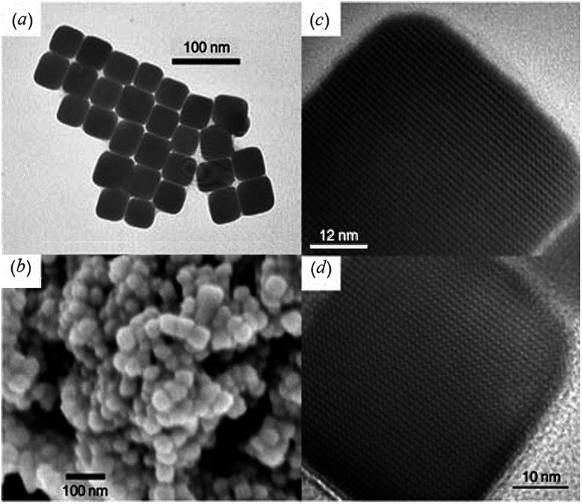 | ||
| Fig. 1 Ag2S nanocubes produced at 393 K:39 (a) TEM image of Ag2S nanocubes; (b) SEM image of clusters formed by Ag2S nanocubes; (c) and (d) HRTEM images of Ag2S nanocubes. Reproduced from ref. 139 with permission from Wiley. | ||
Later, spherical Ag2S nanocrystals were obtained via a modified hot-injection process of the same single-source molecular precursor Ag(SCOPh), which can potentially generate both Ag* and AgS* fragments simultaneously.102 Wang et al.103 obtained Ag2S nanocrystallites by heating molecular precursors such as silver diethyldithiocarbamate (Ag–DDTC) in air at 473 K for 3 h, and used this air-stable molecular precursor as the reactant source. The proposed method was both cost-effective and non-toxic. Monodisperse Ag2S nanoparticles with controlled size were successfully synthesized by thermolysis of harmless silver xanthates as a single-source molecular precursor.104 In one experiment,104 the diameter of the Ag2S nanoparticles ranged from 8.9 ± 1.2 nm to 48 ± 4 nm (Fig. 2). Control of the particle size has been achieved by simply changing the alkyl chain length in the precursors.
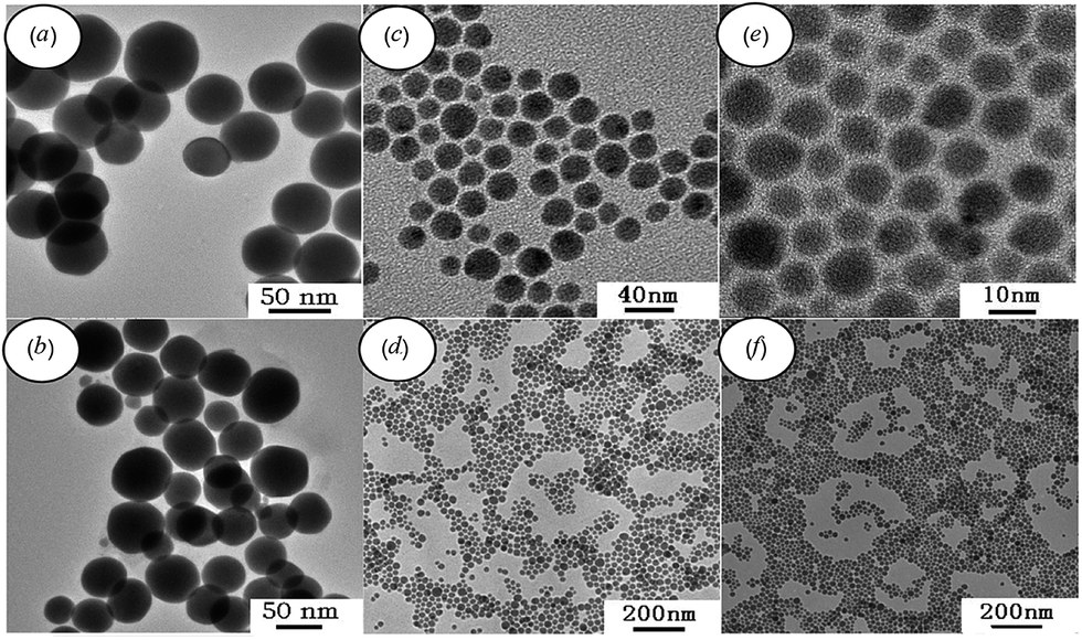 | ||
| Fig. 2 TEM images of Ag2S nanoparticles synthesized by solvent-less thermolysis of (a and b) silver octyl xanthate, (c and d) silver hexadecyl xanthate, and (e and f) silver carnaubyl xanthate. Reprinted from ref. 104 with permission from Elsevier. | ||
2.2 Synthesis of nanostructured Ag2S with different morphology
Recently, great efforts have been focused on the preparation of Ag2S nanoparticles of various morphology, and on the morphology control of the semiconductor nanocrystals.105 For example, Zhao et al.106 prepared rod-like Ag2S nanocrystals using Na2S2O3 as a S source via gamma-ray irradiation of aqueous solutions at room temperature.An alcohol solution method to synthesize nanostructured Ag2S using carbon bisulfide (CS2) as the S source has been described.107 All the products were irregular Ag2S microstructures and nanostructures. When the reaction medium was changed from water and alcohol–water to alcohol, the morphology of synthesized Ag2S changed from big irregular nanosheets to leaf-like nanosheets, elliptical, and Y-shaped flaked Ag2S nanoparticles.
Later, Chen et al.108 reported that leaf-like Ag2S nanosheets were prepared successfully by a facile hydrothermal method from a mixture of alcoholic CS2 solution with an aqueous solution of AgNO3 and NH3.
Ag2S microstructures and nanostructures with different morphologies, including micrometer bars, nanowires, and nanopolyhedrons, have been synthesized by a facile one-step method at room temperature.109 In the proposed method, no organic template materials were added to the reaction mixture, which contained aqueous solutions of AgNO3, NH3, and N2H4CS. By changing the reactant concentration ratio, the size and morphology of prepared Ag2S particles can be easily tuned.
In recent years, polyhedral nanocrystals, including face-centered cubic sulfide nanocrystals,39,110 have been successfully fabricated. Wang et al.110 prepared Ag2S nanocrystals by thermolysis of an organometallic precursor Ag[S2P(OR)2] (R = CnH2n+1). The above-mentioned hydrothermal method has been improved by Dong et al.111 Most of the observed Ag2S nanoparticles looked hexagonal.
Ag2S-poly(N-isopropylacrylamide-co-methacrylic acid) (PNIPAM–MAA) and Ag2S–PNIPAM composite microspheres with patterned surface structures have been synthesized by a polymeric minigel template method.112 The surface structure of Ag2S–PNIPAM–MAA microspheres looks like flowers.
Single-crystalline Ag2S hollow nanohexagons with narrow size distribution were successfully synthesized in aqueous solutions of AgNO3, N2S2O3, and C19H42BrN (CTAB) at 318 K.113
Tetrahedral colloidal crystals of Ag2S nanoparticles have been synthesized from aqueous solutions of AgNO3, NH3, and 1-dodecanethiol (CH3(CH2)11SH) in an autoclave at 473 K for 5 h.114 Due to the high uniformity and van der Waals interactions, Ag2S nanoparticles spontaneously assemble into tetrahedral colloidal aggregates comprising a perfectly ordered 3D superlattice structure (Fig. 3).
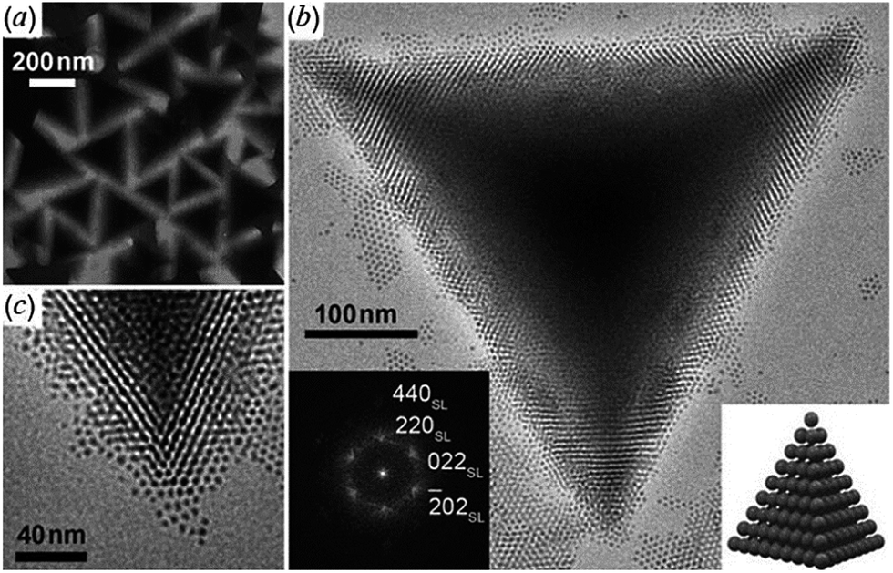 | ||
| Fig. 3 Ag2S tetrahedral superlattice colloidal crystals:114 (a) TEM image at low magnification; (b) a typical HRTEM image of an individual tetrahedron at high magnification; the left inset is the diffraction pattern calculated using fast Fourier transform (FFT) of HRTEM images and the right inset is a scheme of the tetrahedral superlattice colloidal crystal; (c) magnified TEM image of a vertex of the tetrahedron. Reproduced from ref. 114 with permission from Wiley. | ||
A sacrificial core of S nanoparticles is used to synthesize Ag2S hollow nanospheres via a wet chemical method at room temperature.115 S nanoparticles as cores were synthesized from Na2S2O3 in the presence of cetyltrimethyl ammonium bromide aqueous solution. After completion of the formation of cores, the AgNO3 solution was added. Then, the produced particles were washed by a water–ethanol mixture and treated with CS2 for the complete conversion of AgBr to Ag2S, as well as to remove the cores to form Ag2S hollow nanospheres (Fig. 4).
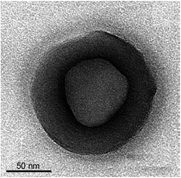 | ||
| Fig. 4 TEM image of a hollow Ag2S particle synthesized from a reaction mixture of silver nitrate and thiosulfate. Reprinted from ref. 115 with permission from Elsevier. | ||
Worm-like Ag2S nanofibers with lengths up to several micrometers and diameters of 25–50 nm have been prepared in reverse microemulsions in the presence of CH3C(S)NH2 as a S source and EDTA as a chelating ligand.116
In study,117 rice-shaped Ag2S nanoparticles were produced by the reaction between Ag(NH3)2+ and Na2S in the presence of polyvinylpyrrolidone (C6H9NO)n (PVP) through a hydrothermal method.
Large, rice-shaped Ag2S particles have been synthesized by hydrochemical bath deposition from aqueous reaction mixture of silver nitrate (AgNO3), Na2S, and Na3Cit.118 Reaction mixture was heated in closed vessel at a temperature of 373 K under the pressure ∼2 × 10⁵ Pa within 2 h.
2.3 Synthesis of Ag2S nanowires
The one-dimensional (1D) nature of Ag2S nanowires endows their unique electrical, optoelectronic, and mechanical properties. Single-crystalline Ag2S nanowires can be expected to have superior properties owing to their anisotropic geometry, and carrier and photon confinement in two dimensions. Conventional nanowire synthesis often requires high temperature and/or various templates.According to,119,120 there are two different routes for the synthesis of 1D nanomaterials, namely, “hard” and “soft” approaches. The first approach includes template-directed synthesis and the vapor–liquid–solid and vapor–solid techniques, which usually require high temperature and pressure. In comparison, the soft approaches, such as hydrothermal/solvothermal processes, the solution–liquid–solid mechanism, and capping agents/surfactant-assisted synthesis, provide a convenient and low-temperature pathway for the fabrication of 1D nanomaterials.
Recently, Ag2S nanowires have been synthesized through the gas–solid reaction route,121 anodic aluminum oxide template method,122 microwave irradiation-assisted method,123 and hydrothermal method with amine ligand.120
Wen et al.121 reported on the successful synthesis of Ag2S nanowires by a simple and mild gas–solid reaction method on Ag substrates. For the nanowire synthesis, the cleaned Ag foil was subjected to preoxidation and sulfidizing by an exposition in an atmosphere of an O2/H2S mixture from room temperature to 313 K in a water bath. The resulting Ag2S nanowires contained one-phase monoclinic acanthite α-Ag2S and had diameter of 40–150 nm and lengths up to 100 μm.
In other syntheses,120 AgNO3 was dissolved in warm octadecylamine solvent, forming silver ammines that were rapidly converted to Ag2S nuclei upon the addition of S powder. After stirring, the system was maintained at 393 K for further growth and crystallization. This process resulted in the generation of ultralong Ag2S nanowires with diameters in the range of 10–30 nm and lengths up to hundreds of micrometers. Authors120 could only obtain uniform nanowires at a temperature neither lower nor higher than 393 K. Synthesized Ag2S nanowires are very sensitive to oxygen and there is a quasi-linear ratio between the current and the logarithm of oxygen pressure. These excellent performances indicate that Ag2S nanowires are promising candidates for photoswitches and room-temperature oxygen sensors.
In work,124 Ag2S nanowires were prepared in anhydrous ethanol through a simple and sacrificial templating solvothermal route. The experimental results124 demonstrated that the reaction temperature, Ag+ concentration, reaction time and solvent played crucial parts in the formation of the Ag2S nanowires. In a typical procedure, a mixture of S powder and Cd(CH3COO)2 were dissolved consecutively in ethylenediamine. The resulting mixture was heated in the autoclave at 473 K for 2 h. Then, as-prepared CdS nanowires and AgNO3 were dissolved in anhydrous ethanol. The resulting mixture was heated in the autoclave at 473 K for 12 h. The addition of excess Ag+ leads to the complete transformation of CdS nanowires to the Ag2S nanowires.
Later,125 a cation-exchange process was used for fabrication of Ag2S nanowires. Authors125 reported a sequential two-step cation exchange process which transformed single-crystal nanowires to twinning nanowires. Specifically, CdS nanowires were used as a template to form CdS–Cu2S core shell nanowires and subsequently twinning Cu2S nanowires through cation exchange. Then, twinning Cu2S nanowires were transformed to Cu2S–Ag2S superlattice nanowires with tunable segment lengths via further cation exchange of Cu+ by Ag+. Fig. 5 shows the schematic synthetic sequence to form Cu2S–Ag2S superlattice nanowires from CdS nanowires. Thus, authors125 have demonstrated that twins created in the cation exchange process of nanowires can be utilized to generate heterostructures in the chain cation exchange steps.
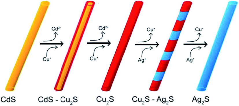 | ||
| Fig. 5 Chain cation exchange process for the formation of a Cu2S–Ag2S superlattice NWs. Reprinted from ref. 125 with permission from ACS. | ||
2.4 Preparing Ag2S nanoparticles and quantum dots
Ag2S quantum dots are treated as an ideal optical probe with fluorescence emission from UV to NIR region because these quantum dots have lower toxicity compared with chalcogenide quantum dots of such heavy metals as Pb, Ca, and Hg.126,127 The synthesis of quantum dots, which can be used as optical probes for in vitro and in vivo molecular imaging, has made great progress.128 The first synthesis of Ag2S quantum dots with emission in the NIR-II region was demonstrated by Du and co-authors.127 In a typical reaction, Ag–DDTC was mixed with oleic acid (CH3(CH2)7CH![[double bond, length as m-dash]](https://www.rsc.org/images/entities/char_e001.gif) CH(CH2)7COOH), 1-octadecane (CH3(CH2)16CH3) and octadecylamine (CH3(CH2)17NH2).
CH(CH2)7COOH), 1-octadecane (CH3(CH2)16CH3) and octadecylamine (CH3(CH2)17NH2).
In study,129 highly monodisperse and water-soluble clusters representing Ag2S quantum dots, covered by ribonuclease-A, were synthesized in aqueous medium via a biomimetic route (i.e., by a method that mimics biochemical processes).
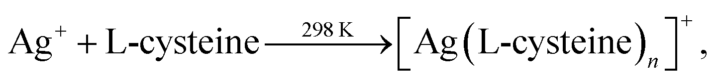
Siva et al.130 noted that the biomolecules assisted the formation of inorganic nanostructures, facilitated electrostatic stabilization, and improved the optical properties of nanoparticles. In study,130 aqueous solutions of AgNO3 and aurochloric acid (HAuCl4) and also a solution of L-cysteine in a mixture of water, ethylene glycol, and ethanol were used for synthesis of L-cysteine-capped Ag2S and Ag3AuS2 nanocrystals. Ag2S nanocrystals were prepared using Ag nuclei as a core. Siva et al.130 proposed the following scheme of formation of Ag2S particles:
 | (2a) |
 | (2b) |
 | (2c) |
There are many other methods for synthesis of nanostructured Ag2S. In study,131 Ag2S nanoparticles were prepared by pyrolysis using AgNO3 and S powder as precursors, and oleylamine C18H35NH2 as a solvent. Oleylamine acts as both a reducing agent and stabilizer during the synthesis. Ag2S nanoparticles of uniform size were prepared by controlling the ratio amounts of AgNO3![[thin space (1/6-em)]](https://www.rsc.org/images/entities/char_2009.gif) :S and ripening time.
:S and ripening time.
Shakouri-Arani and Salavati-Niasari132 produced Ag2S nanoparticles by a solvothermal process via reaction of AgNO3 and a new sulfuring agent from the class of thio Schiff-base (2-(benzylidene amino)benzenethiol C13H11NS) in the presence of various solvents.
Nanostructured Ag2S was obtained in the absence of a surfactant or presence of an anionic surfactant such as sodium dodecyl sulfate (C12H25SO4Na; SDS) or such cationic surfactants as CTAB and polyethylene glycol (PEG) 20000C2nH4n+2On+1 (HO–(C2H4O)n–H). Surfactants were dissolved in solvents such as H2O and 1-butanol C4H9OH.
Experimental results132 indicate that the reaction temperature, presence of surfactant, and type of solvent affect the size of Ag2S nanoparticles. Fig. 6 illustrates the influence of various conditions of synthesis on the formation of Ag2S nanoparticles.
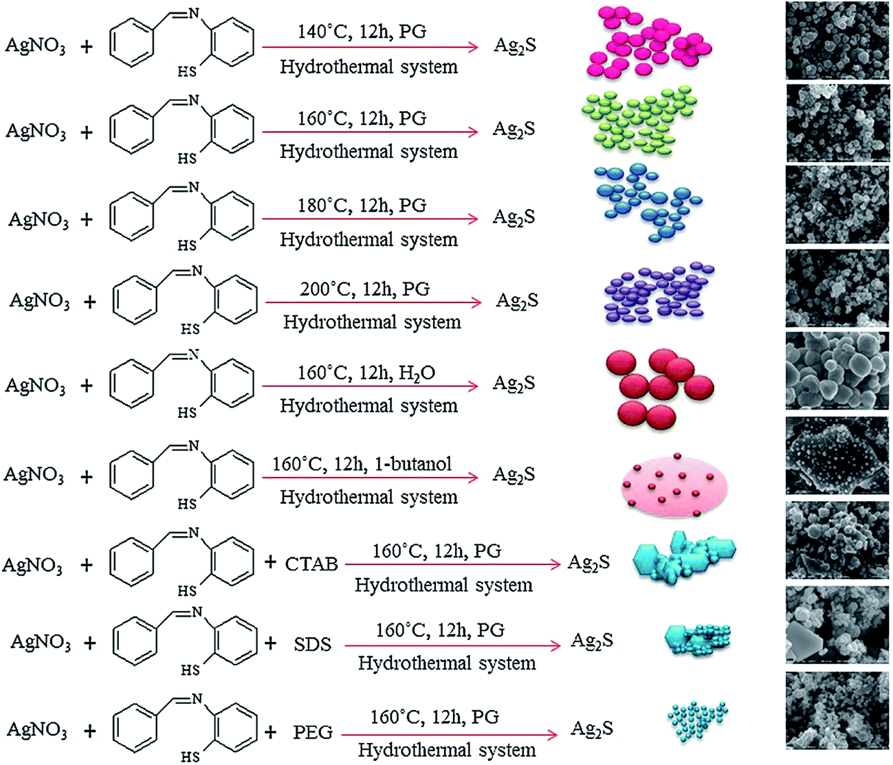 | ||
| Fig. 6 Formation of Ag2S nanoparticles at various conditions (schematic) (PG is propylene glycol (C3H8O2), CTAB is cetyltrimethyl ammonium bromide (C19H42BrN), SDS is sodium dodecyl sulfate (C12H25SO4Na) and PEG is polyethylene glycol 20000 C2nH4n+2On+1). Reprinted from ref. 132 with permission from Elsevier. | ||
An improved hydrothermal/solvothermal method has been developed by Wang et al.133 to prepare nanostructured Ag2S. Using a liquid–solid–solution (LSS) system consisting of an ethanol–linoleic acid liquid phase, solid metal linoleate, and a water–ethanol solution under hydrothermal conditions, monodisperse Ag2S nanocrystals of size 7.3 nm were successfully synthesized.
Biocompatible Ag2S quantum dots were prepared through thermal decomposition of a single-source precursor, Ag–DDTC with CH3(CH2)11SH as a covalent ligand and solvent.134 The reaction mixture was heated to 483 K at a heating rate of 15 K min−1 and kept for 1 h under a N2 atmosphere. As a result, hydrophobic Ag2S quantum dots with an average diameter from 5.4 to 10.0 nm coated with CH3(CH2)11SH as the surface ligand were obtained.
Stable and highly luminescent near-IR emitting Ag2S colloidal quantum dots were prepared by a simple aqueous method using 2-mercaptopropionic acid (C3H6O2S; 2-MPA) as a coating.135 Nanoparticle size can be tuned between 2.3 and 3.1 nm with an emission maximum between 780 and 950 nm.
A similar one-step method was reported by Jiang et al.56 using 3-mercaptopropionic acid (3-MPA) and EG rather than 2-MPA. In this case, the quantum dot surface was terminated with carboxyl groups. The PL emission wavelength of Ag2S quantum dots was broadly tunable, from 510 to 1221 nm, by varying the growth time. Li et al.57 demonstrated that Ag2S quantum dots can be used as NIR luminescent probes for in vivo monitoring of lymphatic and vascular networks with deep penetration. They reported that Ag2S quantum dots can provide spatial resolution of 40 μm during in vivo photoluminescence (PL) imaging, and this allowed them to monitor angiogenesis.
2.5 Hydrochemical deposition of different forms of nanostructured Ag2S
Chemical deposition from aqueous solutions (also termed “chemical condensation method”, and one-pot synthesis in aqueous solutions) and hydrochemical bath deposition are the most popular methods used for the synthesis of nanocrystalline sulfide powders.Hydrochemical bath deposition is a well-known method which allows preparation of colloidal solutions of Ag2S nanoparticles and quantum dots, nanocrystalline and coarse-crystalline Ag2S powders, isolated Ag2S nanoparticles, and different heteronanostructures with Ag2S.
Usually, nanostructured Ag2S synthesizes by hydrochemical deposition from aqueous solutions of AgNO3 and Na2S. Solutions of Na3Cit or the disodium salt of EDTA (Trilon B) are used as complexing agents. Coarse-crystalline Ag2S powder is prepared by hydrothermal synthesis from an aqueous reaction mixture of AgNO3, Na2S and Na3Cit with subsequent heating of a matrix solution with the precipitated powder in a closed vessel at elevated temperature and pressure.
Hydrochemical deposition of Ag2S nanopowders using of Trilon B, and also hydrothermal synthesis of Ag2S powder, are described in study.67
Ag2S deposition in the presence of Trilon B occurs according to the following reaction scheme:
 | (3) |
Trilon B was added with constant stirring to AgNO3 solution, and the prepared solution was then mixed with Na2S solution. During mixing of the solutions, a sulfide formation reaction occurred instantaneously. All nanoparticles were deposited during 2 days. The average size D of Ag2S nanoparticles in the deposited Ag2S nanopowders was 58 ± 8 nm.
Disadvantages of the chemical deposition of Ag2S from aqueous AgNO3, Na2S, and Trilon B solutions are the large size of prepared Ag2S nanoparticles and the presence of a considerable amount of metallic Ag impurity.
Hydrochemical bath deposition using Na3Cit is a well-known, simple and reliable universal “green” method which allows preparation of non-toxic colloidal solutions of Ag2S nanoparticles, isolated Ag2S nanoparticles and quantum dots with protective shells, Ag2S/Ag heteronanostructures, nanocrystalline and coarse-crystalline powders of Ag2S.76,136–139 A weak aqueous solution of AgNO3, which is widely applied in pharmacology and medicine and possesses antibacterial action, is usually used as a source of Ag+ for Ag2S synthesis. Conditions of hydrochemical bath deposition for preparing different forms of nanostructured Ag2S, and the previously unknown possibilities of this method are generalized in study.136
Hydrochemical deposition of nanostructured Ag2S with using Na3Cit is an example of green chemistry because of the design of chemical products and processes that reduce or eliminate the use and generation of hazardous substances.140 Indeed, hydrochemical bath deposition allows one to obtain valuable products from harmless substances using environmentally friendly methods.
In study,136 different forms of nanostructured Ag2S was synthesized by hydrochemical bath deposition from aqueous solutions of AgNO3 and Na2S used as sources of Ag+ and S2−. Na3Cit was used as a complexing agent and electrostatic stabilizer.
The solubility product (Ksp) of Ag2S is very small (according to,141 at 298 K, Ksp = 6.3 × 10−50), and Ag2S is formed from an aqueous solution of AgNO3 and Na2S in a simple reaction
| 2AgNO3 + Na2S = Ag2S↓ + 2NaNO3, | (4) |
A generalized scheme of synthesis of different types of nanostructured Ag2S and Ag2S/Ag heteronanostructures is shown in Fig. 7.
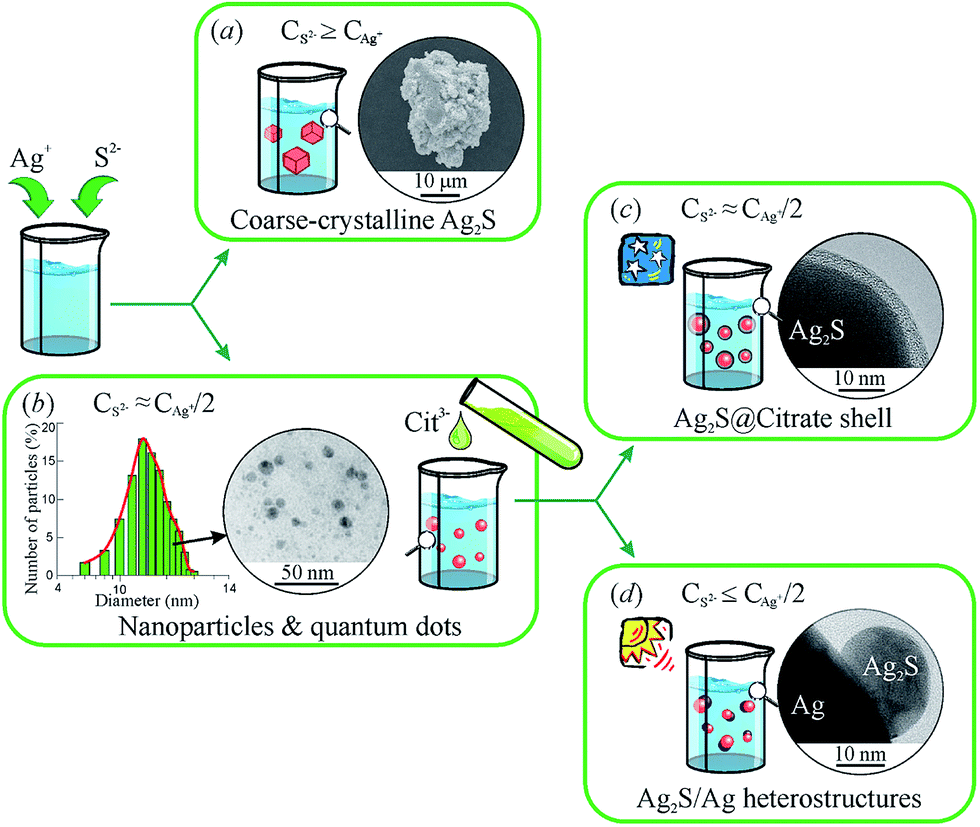 | ||
| Fig. 7 Generalized scheme of the synthesis of various types of nanostructured Ag2S and Ag2S/Ag heteronanostructures: (a) coarse-crystalline Ag2S; (b) Ag2S quantum dots; (c) Ag2S@C core–shell nanoparticle with carbon-containing citrate shell; (d) Ag2S/Ag heteronanostructures. Reproduced from ref. 136 with permission from Wiley. | ||
Coarse-crystalline Ag2S powders are deposited almost instantly from an aqueous solution of AgNO3 and Na2S with a large excess concentration of S2− (CS2− ≥ CAg+) both without and with addition of Na3Cit as a complexing agent at room temperature in the dark (Fig. 7a). Synthesis with excess Na2S and without addition of Na3Cit led to the deposition of Ag2S powder of particle size ∼1000 nm. When Na3Cit was added to reaction mixtures having excess Na2S, the average size of Ag2S particles decreased to ∼200 nm.
If the concentration of S2− is sufficient or differs slightly from the concentration required for the chemical bonding, all Ag+ (i.e. CS2− ≈ CAg+/2 + δ), then addition of Na3Cit to the solution promotes the formation of Ag2S nanoparticles and quantum dots (Fig. 7b). Deposition of Ag2S takes place in neutral medium at pH ≈ 7 by the following reaction scheme
 | (5) |
Na3Cit has a triple role in aqueous solutions of AgNO3 and Na2S.
First, it is a complexing and stabilizing agent during deposition of Ag2S nanoparticles, which occurs both in the light and dark (Fig. 7b). Second, during deposition in the dark, Na3Cit is adsorbed on Ag2S nanoparticles, impeding their agglomeration. In this case, an increased duration of deposition and use of reaction mixtures with an enhanced concentration of Na3Cit leads to the formation of a protective citrate shell on the surface of Ag2S nanoparticles (Fig. 7c). Third, during deposition in the light in aqueous solutions with lowered content of S2−, Na3Cit can reduce Ag+ to metallic silver.142
During deposition in the light, Na3Cit, as a reducing agent, takes part in a photochemical reaction
 | (6) |
In principle, citric acid (harmless standardized food additive E330) can be used as a complexing agent for Ag+, but its application in Ag2S synthesis displaces the equilibrium into the acidic region, which is not desirable.
Nanosized Ag2S powders were prepared from aqueous solutions of AgNO3 and Na2S containing Na3Cit. The concentration of AgNO3 was 50 mmol l−1. The concentration of Na2S in the initial reaction mixtures was slightly over half of the AgNO3 concentration, i.e., CNa2S = (CAgNO3/2) + δ with δ = 0.5 mmol l−1.136 The average particle size (D) in the examined Ag2S nanopowders was about 46 ± 7 nm.
The technology for the production of Ag2S nanopowders with preset nanoparticle size from 20 to 500 nm by hydrochemical deposition has been patented.143
Stable colloidal solutions of Ag2S quantum dots were prepared from the reaction mixtures with AgNO3 concentrations (CAgNO3) from 0.3125 to 2.5 mmol l−1. The Na2S concentration (CNa2S) in the reaction mixtures was slightly over half of the AgNO3 concentration (i.e., CNa2S = (CAgNO3/2) + δ, where δ = 0.01 mmol l−1).136
According to the dynamic light scattering (DLS) data, the size of Ag2S quantum dots in colloidal solutions was ≤20 nm. The DLS zeta-potential measurements of colloidal solutions confirmed that these solutions remained stable for >100 days. The particle size distributions for the colloidal solutions with different size of Ag2S quantum dots and the appearance of these colloidal solutions are shown in Fig. 8a and b.
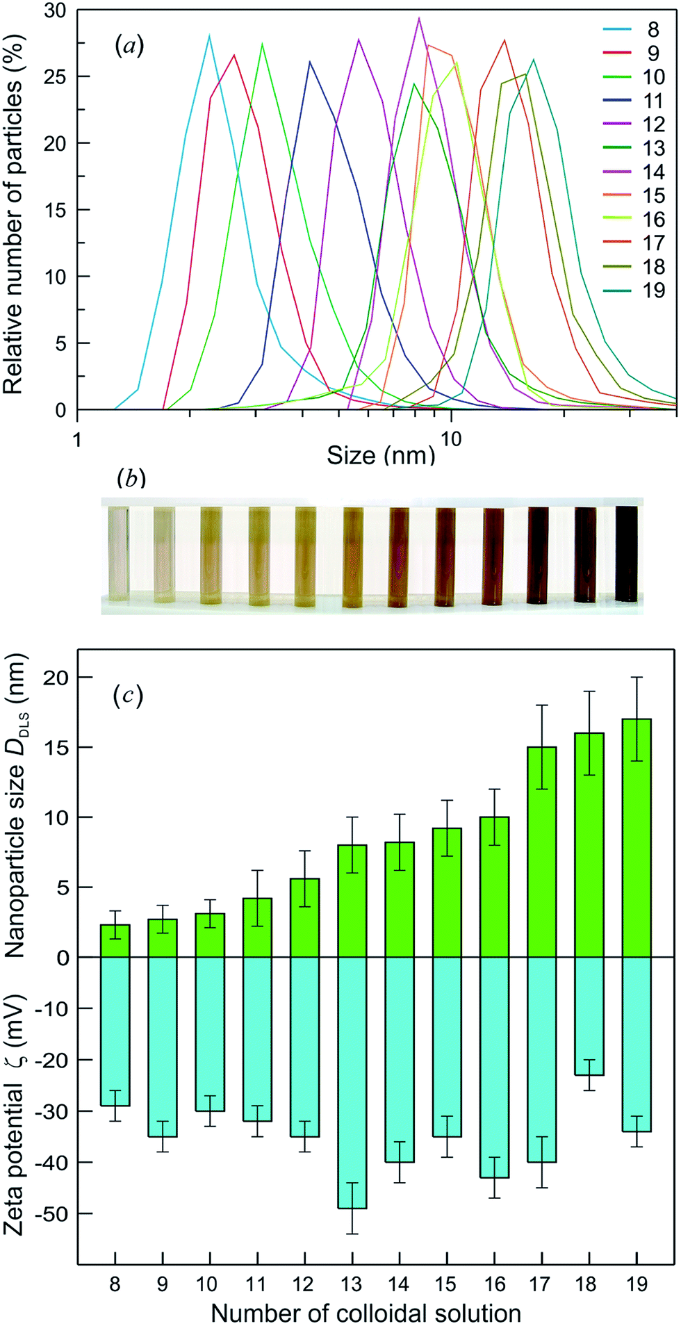 | ||
| Fig. 8 (a) The particle size distributions measured by DLS for colloidal solutions with different average sizes of Ag2S QDs from 2.3 to 17.0 nm, (b) the appearance of these colloidal solutions, and (c) the average size DDLS and zeta potential ζ of Ag2S QDs in colloidal solutions measured 100 days after synthesis. | ||
The zeta potential (ζ) of quantum dots in a solution is an indicator of the system stability. The DLS measurements revealed that 3 days after synthesis, the ζ was −45 to −28 mV, and the quantum dot size was 2–13 nm. The ζ and size of Ag2S quantum dots measured 100 days after synthesis of colloidal solutions remained almost unchanged.136 The comparison of the ζ with the average size (DDLS) of quantum dots for synthesized colloidal solutions 100 days after synthesis is displayed in Fig. 8c. The DDLS of quantum dots was 2 to 17 nm, the value of ζ varied from −49 to −29 mV, and the average ζ was −35 ± 10 mV. It can be seen that, the smaller is the absolute value of ζ, the larger is the size of Ag2S quantum dots.
Fig. 9 presents the size-dependent PL emission spectra of Ag2S colloidal solutions in which the fluorescence of Ag2S quantum dots is tunable from ∼1176 to ∼960 nm by decreasing the nanoparticle DDLS from 15.0 to 2.3 nm. According to,56 the PL peak for Ag2S quantum dots with a size about 1.5 nm was observed at ∼640 nm (see Fig. 9). The PL emission peaks shifted from ∼960 to ∼1170 nm with the size of Ag2S quantum dots increasing from ∼2.3 to 4.2 nm and remained constant at 1166–1176 nm with an increase of the quantum dot size from ∼4.2 to >15 nm. The continuous blue shift of the PL emission of Ag2S quantum dots from ∼1176 to ∼640 nm can be attributed to the strengthened quantum confinement effect and increase in band gap Eg which resulted from the decreasing size of Ag2S quantum dots. This hypothesis is in agreement with experimental data144 on the size-dependent band gap of Ag2S nanopowders. An almost constant position of the PL emission peaks at ∼1166 to 1176 nm for the Ag2S quantum dots with a boundary value of ≥4.2 nm is evidence for transition from the strong quantum confinement regime to a weak quantum confinement regime. According to this hypothesis, the estimated Ag2S exciton radius (Rexc) is less than half of boundary size of 4.2 nm (i.e., ≤2.1 nm).
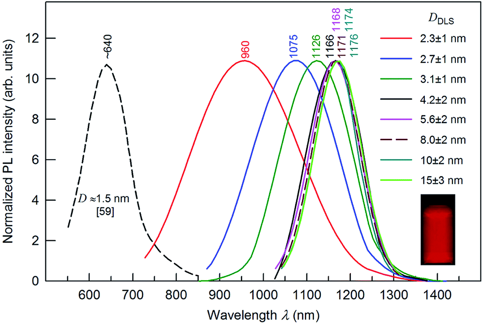 | ||
| Fig. 9 The size-dependent PL emission spectra of Ag2S colloidal solutions with quantum dot size DDLS from 2.3 to 15.0 nm under an excitation of 658 nm. For comparison, the dashed line shows the position of the PL emission peak for Ag2S quantum dots of size ∼1.5 nm.56 The wavelengths corresponding to the maxima of the PL peaks are indicated. The inset presents a fluorescence image of Ag2S colloidal solution of quantum dot size ∼8 nm. | ||
The Rexc for Ag2S, which is calculated by formula (1), is about 1.4 ± 0.1 nm, and the exciton diameter is about 3 nm. According to an analogous estimation,145 the Ag2S exciton diameter ranges from 3.0 to 4.4 nm. A strong blue shift for a quantum dot of size 1.5 nm agrees with data145 on the Ag2S exciton diameter. An estimated exciton diameter ∼3 nm for Ag2S is in satisfactory agreement with the experimental result (4.2 nm),136 which follows from the size-dependent PL emission spectra (see Fig. 9).
The technology for preparing aqueous colloidal solutions of stable Ag2S quantum dots has been patented.146
Ag2S@C nanoparticles with a carbon-containing citrate shell were found in colloidal solutions prepared from an aqueous solutions of AgNO3 and Na2S at concentrations of 5.0 and 2.5 mmol l−1 or 50 and 25 mmol l−1, respectively; the Na3Cit concentration varied from 5 to 100 mmol l−1.68,136,147 Synthesis was carried out at room temperature in the dark.
The X-ray diffraction (XRD) patterns of Ag2S nanopowders deposited from a reaction mixture of AgNO3, Na2S and Na3Cit with concentrations of 5.0, 2.5 and 5.0 mmol l−1, respectively, are shown in Fig. 10A. These nanopowders can be distinguished by their dwell time in the solution (from 20 to 1200 min). The quantitative analysis of the XRD patterns and comparison with data148 have shown that the observed set of diffraction reflections corresponds to nonstoichiometric monoclinic (space group P21/c) acanthite ∼Ag1.93S. The amorphous carbon-containing shell is not visible on the XRD patterns.
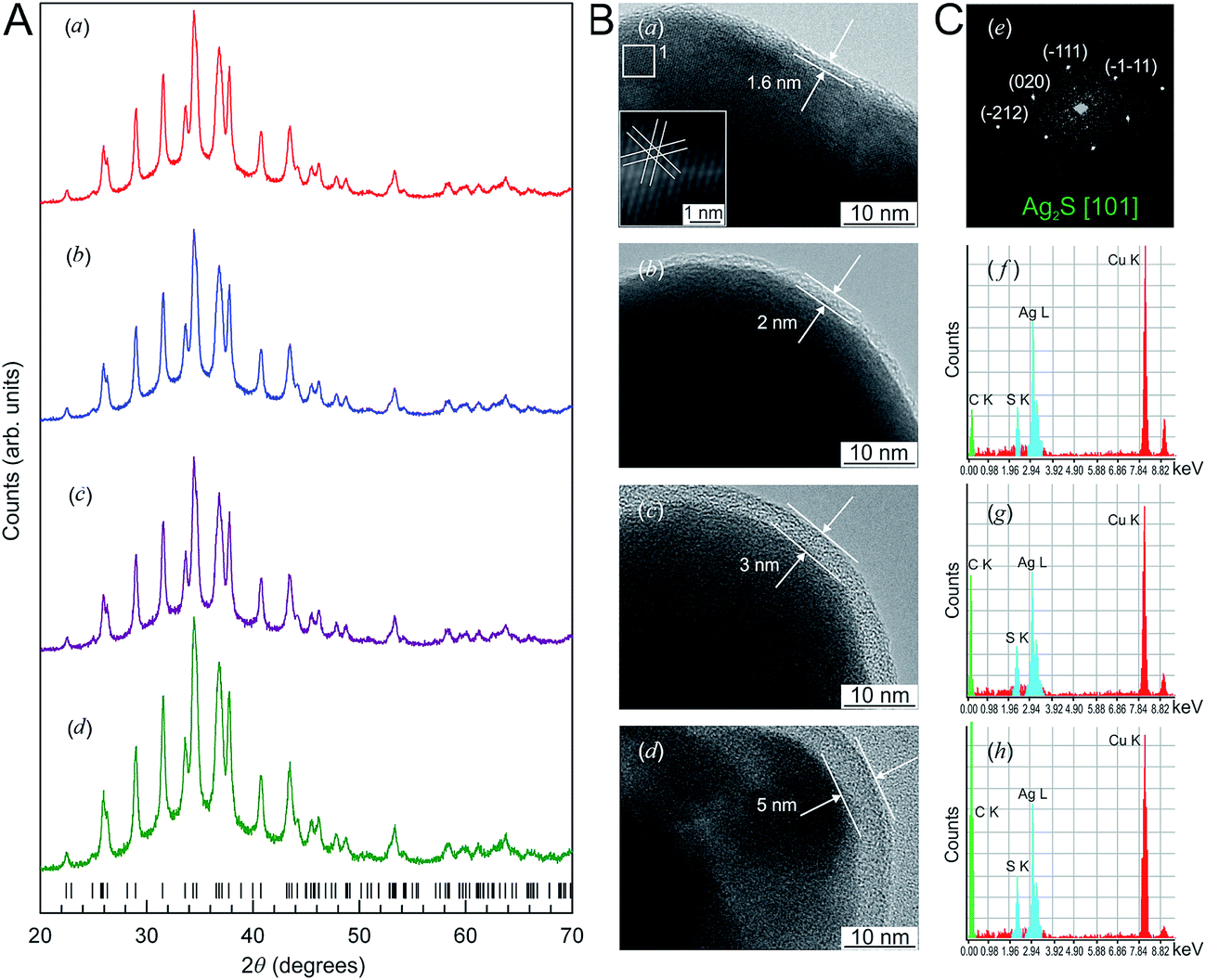 | ||
| Fig. 10 (A) The XRD patterns of monoclinic (space group P21/c) Ag2S nanoparticles and (B) HRTEM images of silver sulfide nanoparticles and the growth of the carbon-containing citrate shell thickness as a function of the nanoparticle dwell time in the solution: (a) 20 min, (b) 40 min, (c) 420 min, (d) 1200 min. Vertical marks on XRD patterns indicate the positions of diffraction reflections of the nonstoichiometric monoclinic α-Ag1.93S phase. (C) (e) Selected area of electron diffraction (SAED obtained from the area 1 of HRTEM nanoparticle (a); (f), (g), and (h) cumulative elemental EDX patterns of nanoparticles (b), (c), and (d), respectively). Reproduced from ref. 136 with permission from Wiley. | ||
The Ag2S nanoparticles extracted from the colloidal solutions have an amorphous shell (Fig. 10B). Other things being equal, the thickness of the shell grows when the nanoparticle dwell time in the colloidal solution containing C6H5O73− (Fig. 10B(a)–(d)) increases, and when the concentration of Na3Cit in the solution increases. A filtered image of area 1 isolated by a white square is shown in Fig. 10B(a). The determination of the interplanar distances of cores confirmed a monoclinic structure of the colloidal Ag2S nanoparticles. Fig. 10C(e) shows as an example of the XRD pattern of the core of the nanoparticle presented in Fig. 10B(a). The observed set of spots (−1−11), (−111), (020), and (−212) corresponds to the [101] plane of the reciprocal lattice of the monoclinic (space group P21/c) α-Ag2S phase with an acanthite structure.
According to the energy-dispersive X-ray spectroscopy (EDX) results, the content of Ag and S in the colloidal core–shell nanoparticles corresponds to Ag1.95–1.98S (Fig. 10C(f)–(h)). The content of carbon is proportional to the intensity of the C Kα line and increases with growth of the shell thickness (Fig. 10C(f)–(h)). Hence, the shell of sulfide nanoparticles contains carbon and is a citrate shell.
Indeed, the three carboxylate groups of Na3Cit have strong affinity for Ag+, which favors the attachment of citrate groups on the surface of the Ag2S nanoparticles and prevents them from aggregating into large particles. In other words, C6H5O73− are adsorbed on the surface of nanoparticles and form a citrate carbon-containing shell that prevents the growth and agglomeration of the nanoparticles.
In the solutions with Na3Cit, the C6H5O73− are adsorbed on the surface of Ag2S nanoparticles and first form an uneven, discontinuous shell. As the Ag2S nanoparticle dwell time in the solution increases, the discontinuities are gradually filled with citrate complexes, and a continuous carbon-containing shell is formed. Gradual adsorption of the citrate complexes by the formed coating promotes smoothing of the shell surface and the growth of the shell thickness.68,136 A continuous shell is formed when CS2− = CAg+/2 and CAg+/4 ≤ CCit3− ≤ CAg+.
The presence of a protective citrate shell is important for the PL of Ag2S nanoparticles. A decrease in nanoparticle size should be accompanied by a blue shift of the PL peak. However, the observed shift may be less than expected because of the formation of surface trap states in the band gap and electron–phonon coupling. To induce a blue shift, one should suppress the formation of surface trap states in the band gap of Ag2S nanoparticles. If the core size is constant, a growth of the protective carbon-containing citrate shell thickness leads to weak intensity enhancement of the PL peaks and a small shift of peaks into the region of lower wavelength (Fig. 11). The position of PL peaks does not depend on the size of an Ag2S core of ≥12 nm.
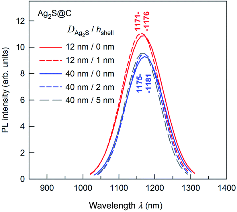 | ||
| Fig. 11 Effect of citrate shell thickness on the PL emission spectra of Ag2S@C core–shell nanoparticles. The wavelengths corresponding to the maxima of the PL peaks are indicated. The wavelength of excitation is 658 nm. | ||
According to,68,136,147 hydrochemical bath deposition allows preparation of Ag2S@C core–shell nanoparticles with pre-assigned sizes of the Ag2S core from 10 and 50 nm and pre-assigned carbon-containing citrate shell thickness from 1.5 to 10 nm.
The process of manufacture of Ag2S@C core–shell nanoparticles with a protective citrate carbon-containing shell by hydrochemical deposition has been patented.149
Comparison of advantages and disadvantages of the main methods for synthesis of different forms of nanostructured Ag2S is presented in summary Table 1.
| Method | Main reagentsa | Forms of nanostructured Ag2S | Advantages | Disadvantages | Ref. |
|---|---|---|---|---|---|
| a PVP – polyvinylpyrrolidone (C6H9NO)n. | |||||
| Hydro-thermal method | AgNO3, CS2, Na2S, NH4OH, (NH2)2CS, C19H42BrN, N2S2O3, Ag[S2P(OR)2] (R = CnH2n+1), CH3(CH2)11SH, PVP | Leaf-like nanosheets, faceted and cubic nanocrystals, hollow nanohexagons, tetrahedral and rice-shaped nanoparticles | Large scale of products | Complicated process, elaborate equipment, non-uniform size distribution, toxic reagents | 108, 110, 111, 113, 114 and 117 |
| Solvo-thermal method | AgNO3, CS2, NH4OH, C2H5OH, PVP | Flake or star-shape nanocrystallite | Low cost reagents | Elaborate equipment, large and non-uniform size, toxic reagents | 107 |
| Solvo-thermal method | AgNO3, C13H11NS, C19H42BrN, C4H9OH | Spherical nanoparticles | Good re-producibility | Elaborate equipment, non-uniform size | 132 |
| Solvo-thermal method | C18H31AgO2, C18H32O2, C2H5OH | Monodisperse nanocrystals | Small size, uniform size distribution | Elaborate equipment | 133 |
| Hydro-chemical deposition | AgNO3, NH4OH, Na2S2O3, (NH2)2CS | Rod-like nanocrystals, nanowires, worm-like nanoparticles, nano-polyhedrons | Easy operation, high yield, good re-producibility | Non-uniform size distribution | 106 and 109 |
| Template method | AgNO3, C4H6O2, (NH4)2S2O6(O2), n-heptane, Na2S2O3, C19H42BrN, CS2 | Microsphere with surface flower-like structure, hollow nanospheres | Controllable size and morphology | Complicated sequential process | 112 and 115 |
| Thermal decomposition (hot-injection process) | C7H5AgOS, C24H51P, (C2H5)2NCSSAg, silver xanthate | Cube-shaped and spherical nanocrystals | Controllable size and morphology, simplicity, safety | Elaborate equipment, sequential process | 39, 102–104 |
| Pyrolysis | AgNO3, S, C18H35NH2 | Nanoparticles | Uniform size | Low yield | 131 |
| Thermal decomposition | (C2H5)2NCS2Ag, CH3(CH2)11SH | Quantum dots | Controllable small size, narrow size distribution | Complicated sequential process | 134 |
| Hydro-thermal method | AgNO3, Na2S, C3H6O2S, CH3COOH, NaOH | Quantum dots | Controllable small size, narrow size distribution | Sequential process | 135 |
| Gas–solid reaction method on Ag substrate | Ag foil, H2S/O2 gas mixture | Nanowires | High aspect ratio, mono-crystallinity | Elaborate equipment, complicated process | 121 |
| Solvo-thermal method | AgNO3, CH3(CH2)17NH2 | Ultralong nanowires | High aspect ratio, mono-crystallinity | Elaborate equipment | 120 |
| Template solvo-thermal method with cation exchange | S, Cd(CH3COO)2, CuCl, AgNO3, anhydrous C2H5OH, (CH2OH)2, NH2CH2CH2NH2 | Nanowires | Controllable phase composition | Elaborate equipment, complicated sequential process | 124 and 125 |
| Hydro-chemical deposition | AgNO3, Na2S, Na3Cit or Trilon B | Nanoparticles, quantum dots | Large scale of products, controllable size, safety, simplicity, non-toxic reagents | Possible presence of metallic Ag impurity in Ag2S | 67, 68, 136 and 144 |
From a comparison of different methods for the synthesis of nanostructured Ag2S, it follows that the most universal method is hydrochemical deposition. This method allows synthesis of colloidal solutions of Ag2S nanoparticles, isolated Ag2S nanoparticles and quantum dots with protective shells, Ag2S/Ag heteronanostructures, nanocrystalline and coarse-crystalline powders of Ag2S. All the forms of nanostructured Ag2S with controllable size can be prepared from the same chemical reagents by varying only their concentrations in solution and the conditions of synthesis. The important advantage of hydrochemical deposition in comparison with other methods is the reproducibility of obtained results.
Hydrothermal and solvothermal synthetic methods are most promising for the preparation of Ag2S in the form of sufficiently large objects with different morphologies (e.g., leaf-like nanosheets, flake or star-shaped crystallites, faceted crystals, tetrahedral and hexagonal particles, hollow particles, etc.). Such objects can have the size from hundreds of nanometers to tens of micrometers.
The preferred method for preparation of Ag2S nanowires with a high aspect ratio (length/diameter) is template synthesis using silver foil or an aluminum oxide template.
3. Crystal structure of Ag2S phases
Ag2S has three basic polymorphic modifications: monoclinic α-Ag2S acanthite, cubic β-Ag2S argentite, and high-temperature cubic γ-Ag2S sulfide. Structures of the different phases of Ag2S were defined originally in studies150–152 and specified later in works.153–155 In works,150–153 the structure of different Ag2S phases was determined on samples of natural minerals such as acanthite and also pseudomorphic acanthite that preserved the cubic morphology of argentite. In works,154,155 an artificial crystal or a powder of Ag2S were used for structure determination. In all cases, these were coarse-grained samples with grain (particle) size of 5–10 μm or larger.Crystal structures of these phases are fairly complex. Hence, in most experimental works devoted to synthesis and properties of Ag2S, description of the crystal structure of the synthesized sulfide is lacking57,156,157 or it is made by comparing experimental XRD or TEM results46,49,56,57,70,73,100,117,158–160 with old XRD data.150 So, in studies,46,49,159–161 without performing full-profile structure refinement, it was suggested that Ag2S synthesized in the form of a film, nanocrystalline powder or nanoparticles has a crystal structure of natural acanthite, whereas in work75 it was assumed that synthesized Ag2S film had the structure of argentite. However, the crystal structure of synthetic Ag2S may have considerable differences that affect the properties of Ag2S. For example, with regard to the XRD patterns of Ag2S nanoparticles, authors159 found a set of spots corresponding to the monoclinic α-Ag2S phase with an acanthite structure, as well as several spots that could not be identified in a monoclinic acanthite-type structure. According to,159 the atomic ratio of Ag to S was estimated to be 1.7 and even 1.1 for nanoparticles with a size of ∼10 and ∼6 nm, respectively. In other words, the examined nanoparticles had the nonstoichiometric chemical composition Ag1.7S and even Ag1.1S.
Careful determination of crystal structures of coarse-crystalline and nanocrystalline acanthite α-Ag2S and argentite β-Ag2S has been performed recently in studies.118,148,162–166
3.1 Artificial coarse-crystalline α-Ag2S
According to,150,153 the structure of acanthite α-Ag2S can be interpreted as a result of distortion of the β-Ag2S argentite structure. Indeed, the unit cells of α-Ag2S acanthite proposed in studies150,153 have axes that can be represented as a combination of axes abcc, bbcc and cbcc of the unit cell of bcc argentite.Recently,118,163 the crystal structure of α-Ag2S acanthite was refined for the first time on synthesized artificial samples of coarse-crystalline powder of Ag2S with the use of full-profile analyses of XRD data. The average particle size D of coarse-crystalline Ag2S powder was estimated from the value of specific surface area Ssp = 1.6 ± 0.1 m2 g−1 and was ∼515 nm.
According to EDX results, the content of Ag and S in the synthesized coarse-crystalline Ag2S powder was 86.8 ± 0.4 and 12.9 ± 0.1 wt%, which corresponds to stoichiometric Ag2S.
The refinement of the crystal structure of synthesized Ag2S provided the following results: synthesized Ag2S had a crystal structure of α-Ag2S acanthite type; monoclinic (space group P21/c) unit cell parameters were a = 0.42264(2) nm, b = 0.69282(3) nm, c = 0.95317(3) nm and β = 125.554(2)°; the site occupancy factor of all crystallographic positions by Ag and S atoms was 1.0; the Rietveld reliability factor RI (RB) was 0.0247. These unit cell parameters were in good agreement with the data.153
Thus, artificial coarse-grained Ag2S is stoichiometric. The arrangement of Ag and S atoms in the unit cell of artificial monoclinic (space group P21/c) Ag2S with an α-Ag2S acanthite type structure is displayed in Fig. 12.
 | ||
| Fig. 12 Monoclinic (space group P21/c) unit cell of Ag2S with an acanthite structure (only the atoms entering into the unit cell and the nearest bonds between them, Ag1–S and Ag2–S, of length 0.2511 and 0.2548 nm, respectively, are shown). Reprinted from ref. 118 with permission from Elsevier. | ||
3.2 Crystal structure and nonstoichiometry of nanostructured α-Ag2S
Determination of the influence of nanoparticle size on their nonstoichiometry is a fundamental scientific problem.A nanostructured Ag2S has been studied extensively in the past two decades. However, until lately, there were no experimental works on the determination of the crystal structure of nanocrystalline Ag2S.
Determination of the structure of nanocrystalline Ag2S has been done in study.148
The nanocrystalline powder of Ag2S was synthesized by chemical deposition from aqueous solution of AgNO3 and Na2S containing Na3Cit as a complexing and stabilizing agent.
The XRD pattern of synthesized Ag2S nanopowder is shown in Fig. 13. According to the BET data, the particle size of the nanopowder was 44 ± 5 nm.
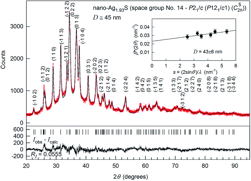 | ||
Fig. 13 The experimental ( ) and calculated ( ) and calculated ( ) XRD patterns of Ag1.93S nanopowder deposited from a reaction mixture of AgNO3, Na2S and Na3Cit having concentrations 0.05, 0.025, and 0.025 mol l−1, respectively. The difference between the experimental and calculated XRD patterns (Iobs − Icalc) is shown in the lower part of the figure. The inset presents the estimate of the average CSRs size from the broadening of non-overlapping diffraction reflections. The XRD pattern is recorded in CuKα1 radiation. Reproduced from ref. 148 with permission from the PCCP Owner Societies. ) XRD patterns of Ag1.93S nanopowder deposited from a reaction mixture of AgNO3, Na2S and Na3Cit having concentrations 0.05, 0.025, and 0.025 mol l−1, respectively. The difference between the experimental and calculated XRD patterns (Iobs − Icalc) is shown in the lower part of the figure. The inset presents the estimate of the average CSRs size from the broadening of non-overlapping diffraction reflections. The XRD pattern is recorded in CuKα1 radiation. Reproduced from ref. 148 with permission from the PCCP Owner Societies. | ||
Preliminary analysis revealed that the synthesized nanocrystalline powder had a monoclinic (space group P21/c) α-Ag2S acanthite-type structure. The XRD reflections of the nanopowder were broadened and, therefore, the reflections located close to each other overlapped. The average size D of coherent scattering region (CSR) estimated from broadening of non-overlapping diffraction reflections (−102), (110), (−113), (−104), (031) and (014) was 43 ± 6 nm.
The coordinates of Ag and S atoms and unit cell parameters for Ag2S nanopowder (Table 2) are close to those for coarse-crystalline Ag2S. However, the occupancy of crystallographic positions 4(e) by Ag1 and Ag2 atoms was ∼0.97 and ∼0.96, respectively (Table 2). Hence, Ag2S nanoparticles of size less than ∼50 nm are nonstoichiometric, have a composition of ∼Ag1.93S and contain vacant sites in the metal sublattice.
| Atom | Position and multiplicity | Atomic coordinates | Occupancy | B iso × 10−4 (pm2) | ||
|---|---|---|---|---|---|---|
| x/a | y/b | z/c | ||||
| Ag1 | 4(e) | 0.0715 | 0.0151(0) | 0.3093(9) | 0.97 | 10.05(5) |
| Ag2 | 4(e) | 0.7264 | 0.3240(9) | 0.4375(0) | 0.96 | 7.44(6) |
| S | 4(e) | 0.4920 | 0.2339(8) | 0.1321(1) | 1.00 | 1.960 |
3.3 Acanthite α-Ag2S–argentite β-Ag2S phase transformation
For the first time, complex in situ high-temperature XRD and SEM study of the α-Ag2S (acanthite) to β-Ag2S (argentite) phase transformation in nanocrystalline and coarse-crystalline powders of Ag2S has been carried out in works.162,165,166 Until lately, few data on acanthite–argentite phase transformation were obtained only on bulk coarse-crystalline Ag2S samples.The low-temperature monoclinic phase α-Ag2S (acanthite) exists at temperatures below ∼450 K. Argentite β-Ag2S has a bcc sublattice of S atoms and exists in the temperature interval 452–859 K.
When argentite β-Ag2S is cooled below 450 K under equilibrium conditions, a polymorphous phase transformation takes place that gives rise to monoclinic acanthite α-Ag2S. This transformation is accompanied by distortion of the bcc sublattice of S atoms to the monoclinic sublattice. The Ag atoms statistically distributed in positions of the bcc structure of argentite are concentrated in the positions of the monoclinic structure of acanthite, and occupy them with probability close to 1.
To precisely determine the phase transformation temperature, Ag2S powders were studied via differential thermal analysis-differential thermal gravimetry (DTA-DTG) upon heating and cooling. During heating, the DTA curves had one endothermic peak at about 449–450 K, which corresponded to the α-Ag2S (acanthite)–β-Ag2S (argentite) phase transformation. In cooling from 500 K to room temperature, the DTA dependencies exhibited an exothermal peak related to the argentite-to-acanthite phase transformation towards a lower temperature range by ∼20 K. The presence of the temperature hysteresis (Ttrans) means this was a first-order reversible acanthite–argentite transformation. The enthalpy of the phase transformation (ΔHtrans) was ∼3.7–3.9 kJ mol−1, which is very close to that determined in works167–170 (ΔHtrans = 4.0 ± 0.5 kJ mol−1).
The XRD patterns for coarse-crystalline Ag2S powder collected at 300, 433, 453 and 503 K, and the XRD patterns for nanocrystalline Ag2S powder at 300, 398 and 463 K are shown in Fig. 14. The XRD patterns recorded at T < 450 K (Fig. 14a and c) contained the diffraction reflections of monoclinic (space group P21/c) α-Ag2S acanthite. The average particle size D in the nanopowder estimated from broadening of diffraction reflections was ∼60 nm. According to the DTA data, the transformation of acanthite α-Ag2S into argentite β-Ag2S takes place at ∼449–450 K. Indeed, the XRD patterns recorded at T ≥ 453 K contained diffraction reflections of cubic (space group Im![[3 with combining macron]](https://www.rsc.org/images/entities/char_0033_0304.gif) m) β-Ag2S argentite. The refinement of the XRD pattern (Fig. 14b) showed that coarse-crystalline Ag2S at 503 K contained one phase with a cubic (space group no. 229 – Imm (I4/m2/m) (O9h)) structure of β-Ag2S argentite (Table 3). According to high-temperature XRD data,162,166 the unit cell of β-Ag2S argentite includes two Ag2S formula units. Two S atoms occupy crystallographic positions 2(a) and form a bcc sublattice. Four Ag atoms in β-Ag2S argentite are statistically distributed in 54 positions 6(b) and 48(j) with the occupation probabilities ∼0.0978 and ∼0.0711, respectively (Table 3).
m) β-Ag2S argentite. The refinement of the XRD pattern (Fig. 14b) showed that coarse-crystalline Ag2S at 503 K contained one phase with a cubic (space group no. 229 – Imm (I4/m2/m) (O9h)) structure of β-Ag2S argentite (Table 3). According to high-temperature XRD data,162,166 the unit cell of β-Ag2S argentite includes two Ag2S formula units. Two S atoms occupy crystallographic positions 2(a) and form a bcc sublattice. Four Ag atoms in β-Ag2S argentite are statistically distributed in 54 positions 6(b) and 48(j) with the occupation probabilities ∼0.0978 and ∼0.0711, respectively (Table 3).
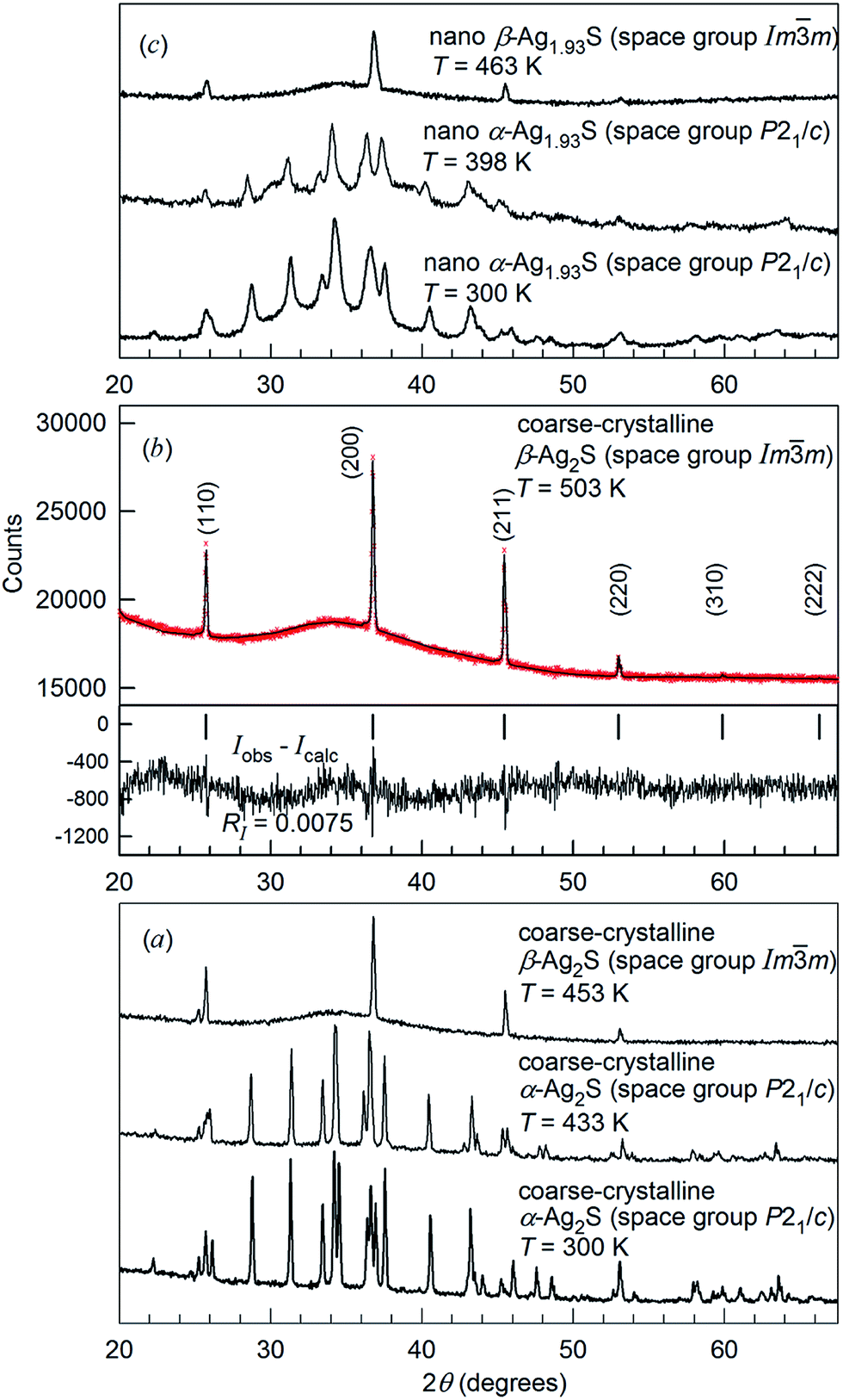 | ||
Fig. 14 Evolution of XRD patterns of silver sulfide at heating.162,165,166 (a) XRD pattern of coarse-crystalline silver sulfide with a monoclinic (space group P21/c) α-Ag2S acanthite-type structure at 300 and 433 K, and with a cubic (space group Imm) β-Ag2S argentite-type structure at 453 K. (b) Experimental ( ) and calculated ( ) and calculated ( ) XRD patterns of coarse-crystalline silver sulfide with cubic (space group Imm) β-Ag2S argentite-type structure at 503 K and the difference (Iobs − Icalc) between the experimental and calculated XRD patterns; the ticks correspond to reflections of cubic argentite β-Ag2S. (c) XRD patterns of nanocrystalline Ag1.93S with a monoclinic (space group P21/c) acanthite-type structure at 300 and 398 K, and with a cubic (space group Imm) β-Ag2S argentite-type structure at 463 K, respectively. Reproduced from ref. 162 and 166 with permission from the PCCP Owner Societies. ) XRD patterns of coarse-crystalline silver sulfide with cubic (space group Imm) β-Ag2S argentite-type structure at 503 K and the difference (Iobs − Icalc) between the experimental and calculated XRD patterns; the ticks correspond to reflections of cubic argentite β-Ag2S. (c) XRD patterns of nanocrystalline Ag1.93S with a monoclinic (space group P21/c) acanthite-type structure at 300 and 398 K, and with a cubic (space group Imm) β-Ag2S argentite-type structure at 463 K, respectively. Reproduced from ref. 162 and 166 with permission from the PCCP Owner Societies. | ||
m (I4/m2/m) (O9h)) coarse-crystalline silver sulfide β-Ag2S (β-Ag2.01S) with an argentite-type structure at 503 K:162,166,166Z = 2, a = b = c = 0.4874(1) nm
| Atom | Position and multiplicity | Atomic coordinates | Occupancy | B iso × 10−4 (pm2) | ||
|---|---|---|---|---|---|---|
| x | y | z | ||||
| Ag1 | 6(b) | 0 | 0.5 | 0.5 | 0.0978(7) | 0.50 |
| Ag2 | 48(j) | 0 | 0.3306(5) | 0.4122(7) | 0.0711(0) | 0.50 |
| S | 2(a) | 0 | 0 | 0 | 1.00(0) | 0.50 |
A structure with such small occupancies can be stable only if the mobility of Ag atoms/ions is very high. The amount of Ag+ in argentite β-Ag2S is much smaller than the number of sites of the cation sublattice. Therefore, significant positional disorder in an arrangement of Ag+ and a gigantic (>92%) concentration of vacant sites facilitate the “jumping” of cations and provide the superionic conductivity of the β-Ag2S phase.
The unit cell of cubic (space group Imm) β-Ag2S argentite is shown in Fig. 15. Detailed crystallographic information on β-Ag2S argentite presented as “Crystal structure data” in the CIF-file attached to article.162 This CIF number 1062400, which was placed on the Cambridge Crystallographic Data Centre (CCDC) website, can be found at the following electronic address.171
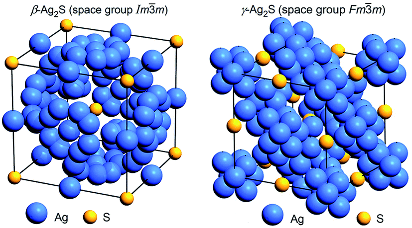 | ||
| Fig. 15 The arrangement of Ag and S atoms in the unit cells of cubic (space group Imm) β-Ag2S argentite162 and cubic (space group Fmm) γ-Ag2S.155 Positions of silver sublattices on which Ag atoms are statistically distributed are shown. Reproduced from ref. 162 with permission from the PCCP Owner Societies. | ||
Thus, heating of monoclinic α-Ag2S acanthite up to ∼449–450 K leads to a polymorphic phase transition with the formation of bcc β-Ag2S argentite.
SEM images of the acanthite-to-argentite transformation occurring in nanocrystalline and coarse-crystalline Ag2S powders are shown in Fig. 16.
 | ||
| Fig. 16 The transformation of acanthite α-Ag2S into argentite β-Ag2S. Upper row: (a and b) the initial nanopowder and (c) its cumulative elemental EDX pattern. Second row: (d–f) the argentite particles are growing on the electron beam-heated surface area. The white dotted lines show the surface areas of Ag2S powders heated by the electron beam. Reproduced from ref. 162 with permission from the PCCP Owner Societies. | ||
In the upper row (Fig. 16a–c) the initial nanopowder with a surface area (for which the elemental chemical composition was determined by EDX) as well as the cumulative elemental EDX pattern of the initial powder are shown. According to the EDX data (Fig. 16c), the content of Ag and S in the Ag2S nanopowder determined from the integral intensities AgL and SK lines were 86.8 ± 0.4 and 13.1 ± 0.1 wt%. This corresponds to a sulfide which is close to the stoichiometric composition of Ag2S but with small deficiency of silver. The second row (Fig. 16d–f) show a SEM image of the electron beam-heated surface area, upon which argentite particles are growing, and of the same area (side view) with grown argentite crystals.
Short pyramidal nuclei of argentite crystallites (whose base was about 50–80 nm in thickness) appeared on the surface of Ag2S powder particles ∼30 s after the start of heating. As a result of heating, the nuclei grew quickly, taking the shape of whiskers, and in ∼5 min covered the entire surface of the acanthite particle.
The sequence of formation and growth of argentite nanoparticles can be conventionally divided into four stages. First, as a result of electron-beam irradiation of acanthite, the particles are heated. Second, the phase transformation leads to the formation of argentite, so the appearance and growth of argentite nuclei take place on the surface of acanthite particles. The third stage is connected with the growth of argentite particles as a result of further heating and the argentite nuclei interacting with the low-temperature phase of acanthite acting as a donor. The growth of argentite particles ends at the fourth stage when no low-temperature acanthite remains in the surface layer.
The formation of argentite was also confirmed by HRTEM data. Fig. 17 demonstrates the HRTEM and TEM images of Ag2S nanopowder before and after radiation heating.162 In Fig. 17a, the interplanar distance is 0.309 nm and clearly visible, which coincides with the distance d(110) between atomic planes (110) of Ag2S with a monoclinic (space group P21/c) α-Ag2S acanthite structure. Upon radiation heating of the nanopowder, the HRTEM image exhibits an interplanar distance of 0.245 nm (Fig. 17b). This corresponds to the distance between the atomic planes (200) of cubic (space group Imm) Ag2S with a β-Ag2S argentite structure. The insets in Fig. 17 correspond to the TEM images of these nanopowders of Ag2S before and after heating.
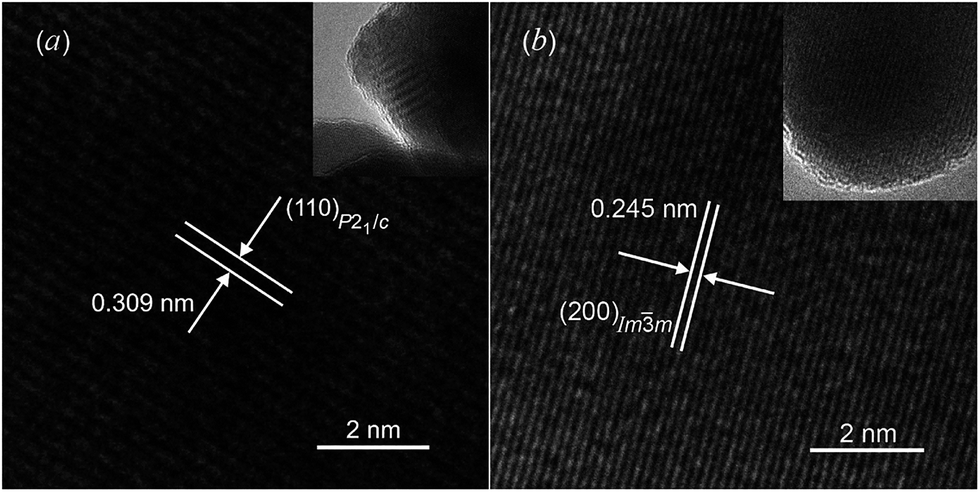 | ||
| Fig. 17 HRTEM images of silver sulfide nanoparticles: (a) the interplanar distance (0.309 nm) observed before heating corresponds to monoclinic silver sulfide with an α-Ag2S acanthite-type structure; (b) the interplanar distance (0.245 nm) observed after heating corresponds to a cubic silver sulfide with β-Ag2S argentite-type structure. The insets show the TEM images of nanoparticles at lower magnification. Reproduced from ref. 162 with permission from the PCCP Owner Societies. | ||
3.4 Crystal structure of the γ-Ag2S phase and distributions of Ag atoms in cubic Ag2S
At temperatures above 860 K, Ag2S contains a cubic (space group Fmm (F4/m2/m) (O5h)) γ-Ag2S phase. The unit cell of the γ-Ag2S phase includes four formula units of Ag2S (z = 4). The first structural model of high-temperature cubic γ-Ag2S was proposed in study.172 According to,172 four S atoms occupy crystallographic positions 4(a) and form a fcc sublattice, and eight Ag atoms are statistically distributed in 8(c) and 32(f) positions. Blanton et al.,155 using high-temperature XRD data, refined the model172 by distributing Ag atoms on positions 48(i) also (Table 4). According to,155 at 923 K, eight Ag atoms are statistically distributed in 88 positions 8(c), 32(f) and 48(i) with the occupation probabilities ∼0.088, ∼0.15, and ∼0.027, respectively. Model155 suggests some Ag deficiency in the γ-phase corresponding to nonstoichiometric Ag1.7S. Fig. 15 shows the crystal structure of γ-Ag2S proposed in study.155
m (F4/m2/m) (O5h)) γ-Ag2S silver sulfide at 923 K:155Z = 4, a = b = c = 0.62831(8) nm
| Atom | Position and multiplicity | Atomic coordinates | Occupancy | ||
|---|---|---|---|---|---|
| x | y | z | |||
| Ag1 | 8(c) | 0.25 | 0.25 | 0.25 | 0.088(7) |
| Ag2 | 32(f) | 0.303(4) | 0.303(4) | 0.303(4) | 0.15(1) |
| Ag3 | 48(i) | 0.5 | 0.381(4) | 0.381(4) | 0.027(3) |
| S | 4(a) | 0 | 0 | 0 | 1 |
Using the temperature dependences of the crystal lattice parameters of monoclinic acanthite α-Ag2S, cubic argentite β-Ag2S, and cubic phase γ-Ag2S, it is possible to estimate the interatomic distances in these phases at comparable temperatures close to the α-Ag2S–β-Ag2S and β-Ag2S–γ-Ag2S transformation temperatures. The least distance between the Ag1 and Ag1 atoms in the crystal lattice of monoclinic α-Ag2S acanthite at 433 K is 0.3351 nm, and the least distance between the Ag1 and Ag2 atoms is in the interval from 0.3085 to 0.3200 nm.166,173 The covalent diameter of the Ag atom is ∼0.292 nm. With that in mind, it is clear that Ag atoms in monoclinic acanthite are at rather large distances from each other and, therefore, occupy their crystallographic sites with a probability ∼1. According to,166,173 in the crystal lattice of cubic β-Ag2S argentite at 443 K, the least possible distance between the Ag1 and Ag1 atoms is 0.2428 nm, between the Ag1 and Ag2 atoms is from 0.0927 to 0.2971 nm, and between the Ag2 and Ag2 atoms is from 0.0988 to 0.2998 nm. Thus, in cubic argentite, the possible distances between Ag atoms are too small for the 6(b) and 48(j) positions to be occupied by Ag atoms with a probability of 1. Indeed, the occupancies of the 6(b) and 48(j) positions by Ag atoms in β-Ag2S (in other words, the probabilities of finding Ag atoms in the 6(b) and 48(j) sites) are very small and equal to ∼0.0978 and ∼0.0711, respectively. In the cubic γ-Ag2S phase, the possible distances between Ag atoms are too small for the 8(c), 32(f) and 48(i) positions to be occupied by Ag atoms with a probability of 1. Therefore, the probabilities of filling of the 8(c), 32(f) and 48(i) sites by Ag atoms are <0.1. Physically, this means that Ag atoms in the lattices of cubic β-Ag2S and γ-Ag2S phases are in constant motion over all possible crystallographic positions. It is this constant motion of Ag atoms that provides the stability of crystal lattices of cubic β-Ag2S and γ-Ag2S phases, and their superionic conductivity as distinct from the semiconducting α-Ag2S acanthite.
4. Effect of small particle size on the thermal expansion and heat capacity of Ag2S
For the application of nanocrystalline Ag2S in infrared equipment, solar-energy converters and resistive switches, it is necessary to have information about the variation in the thermal expansion coefficient of different Ag2S phases versus the temperature, and about the effect of particle size on such lattice properties of Ag2S as heat capacity and thermal expansion.According to,169 the linear thermal expansion coefficient αac of acanthite is ∼20 × 10−6 K−1. According to,174 in the temperature range 293–450 K, the αac of bulk acanthite is 16.8 × 10⁻⁶ K−1, and the linear thermal expansion coefficient αarg of bulk argentite is 45.8 × 10⁻⁶ K−1 from ∼460 to 570 K.
A systematic in situ study of the thermal expansion of coarse-crystalline and nanocrystalline powders of Ag2S in the region of existence of monoclinic α-Ag2S acanthite and cubic β-Ag2S argentite has been done for the first time in works166,173via a high-temperature XRD method. Recently, direct dilatometric measurements of the thermal expansion of coarse-crystalline and nanocrystalline Ag2S at 290 to 970 K in the region of existence of monoclinic acanthite α-Ag2S, argentite β-Ag2S, and γ-Ag2S phases, as well as the heat capacity of nanocrystalline Ag2S in the temperature interval from 300 to 930 K, have been carried out in study.175
The average particle size in coarse- and nanocrystalline Ag2S powders was ∼430 and ∼66 nm.
The effect of temperature on the evolution of XRD patterns of nanocrystalline Ag2S is shown in Fig. 14. The XRD patterns of Ag2S recorded at <450 K contain the diffraction reflections of monoclinic (space group P21/c) acanthite α-Ag2S, and the XRD patterns recorded at >450 K contain the diffraction reflections of cubic (space group Imm) argentite β-Ag2S. Thus, a polymorphous phase transformation of monoclinic acanthite α-Ag2S into bcc argentite β-Ag2S takes place at ∼448–453 K.
According to data from high-temperature XRD studies,166,173 the isotropic (averaged in all crystallographic directions) linear thermal expansion coefficient αac-nano of nanocrystalline acanthite in the temperature range 300–400 K is
| αac-nano(T) = 13.4 × 10⁻⁶ + 2.7 × 10⁻⁸T ± 2 × 10⁻⁶ [K−1]. | (7) |
The αac-nano of nanocrystalline acanthite is ∼25% larger than the analogous coefficient αac of coarse-crystalline acanthite. The difference in the coefficients αac-nano and αac is due to the small particle size in nanocrystalline acanthite. Earlier, a similar difference in the linear thermal expansion coefficients of nanocrystalline film and coarse-grained sample was observed for PbS.4,176,177
According to,166,173 the dependence of αarg on the annealing temperature T in the range 443–623 K can be represented as
| αarg(T) = 84.5 × 10⁻⁶ − 6.9 × 10⁻⁸T ± 3 × 10⁻⁶ [K−1]. | (8) |
The temperature dependences of αaver(T) for coarse- and nanocrystalline Ag2S measured by dilatometry are demonstrated in Fig. 18. The largest coefficient αaver(T) in the examined temperature range 293–970 K belonged to nanocrystalline Ag2S produced from a powder with an average particle size of ∼66 nm. The average linear thermal expansion coefficients αaver of coarse-crystalline and nanocrystalline acanthite α-Ag2S and argentite β-Ag2S measured in works166,173 by high-temperature XRD are shown in Fig. 18 for comparison. The results of dilatometric and high-temperature XRD measurements of αaver agree with each other satisfactorily.
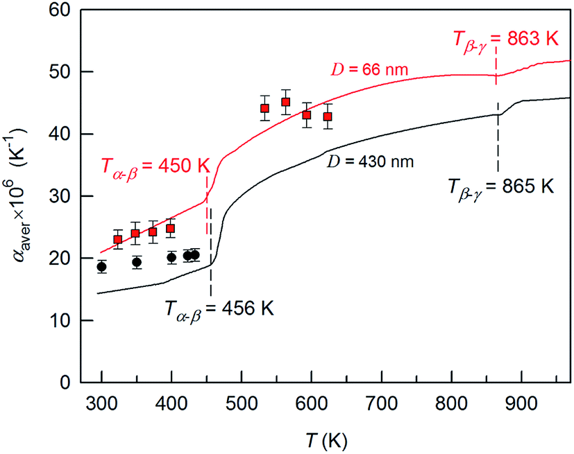 | ||
Fig. 18 The average thermal expansion coefficients αaver of coarse- and nanocrystalline silver sulfide measured by dilatometry in the temperature range 293–970 K. The thermal expansion coefficient αaver of coarse-crystalline ( ) and nanocrystalline ( ) and nanocrystalline ( ) silver sulfides measured in works166,173 by the high-temperature XRD method are shown for comparison. The discontinuity regions of the coefficient α(T) are shown by a dotted line. Reproduced from ref. 175 with permission of Springer. ) silver sulfides measured in works166,173 by the high-temperature XRD method are shown for comparison. The discontinuity regions of the coefficient α(T) are shown by a dotted line. Reproduced from ref. 175 with permission of Springer. | ||
The heat capacity of Ag2S nanopowder changes monotonically with rising temperature, except for the transition regions (Fig. 19). In the temperature range 300–450 K, the heat capacity increases and then, near the transition temperature Tα–β, it experiences a discontinuity. In the region of existence of the β-Ag2S phase, in the temperature interval from ∼470 to ∼840 K, the heat capacity first decreases slightly to ∼670 K and then grows slightly to the transition temperature Tβ–γ, where it discontinues. As the temperature increases further to ∼890 K, a small reduction of the heat capacity is observed and, at T > 890 K, the heat capacity increases slightly. According to the heat capacity measurements, the transition temperatures Tα–β and Tβ–γ were 451 and 858 K, respectively.
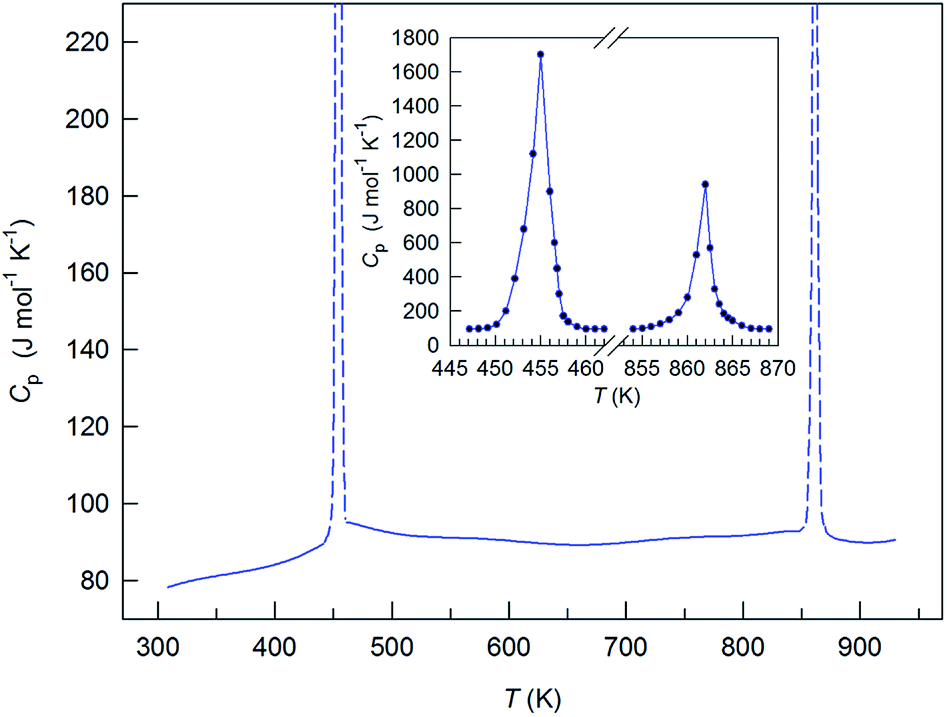 | ||
| Fig. 19 Heat capacity of silver sulfide nanopowder. The inset shows the spasmodic change of Cp for Ag2S nanopowder in the regions of α-Ag2S–β-Ag2S and β-Ag2S–γ-Ag2S transformations. Reproduced from ref. 175 with permission of Springer. | ||
The peaks of the heat capacity Cp of Ag2S nanopowder in the α-Ag2S–β-Ag2S and β-Ag2S–γ-Ag2S transformation regions were symmetric rather than λ-shaped (Fig. 19, inset). A symmetric shape of the observed peaks is more characteristic of first-order phase transitions. The heat capacity peaks were very narrow (the width of peak base was about 8 K), which is also typical for first-order phase transitions.
The enthalpy of the phase transformations α-Ag2S–β-Ag2S and β-Ag2S–γ-Ag2S was estimated to be ΔHα–β = 4.2 ± 0.4 and ΔHβ–γ = 1.2 ± 0.3 kJ mol−1, respectively. According to data,167,168,170 the enthalpy ΔHα–β is 3.98, 3.93, and 4.06 kJ mol−1, respectively. According to,162,165,166 the enthalpy ΔHα–β is 3.7–3.9 kJ mol−1. As reported in,168,170 the enthalpy ΔHβ–γ of the transformation of argentite β-Ag2S into the γ-Ag2S phase was ∼0.50 and ∼0.78 kJ mol−1, respectively. Within the measurement error, the obtained values of enthalpies ΔHα–β and ΔHβ–γ were close to the literature data.
For comparison, Fig. 20 presents experimental data on the heat capacity Cp of nanocrystalline Ag2S175 and the most reliable experimental data from the literature on the Cp of coarse-grained Ag2S170 obtained with the use of adiabatic-shell calorimetry. In the whole temperature region, the heat capacity of nanocrystalline Ag2S measured in study175 was 1–4% larger than the heat capacity of coarse-crystalline sulfide.170 The measured heat capacity Cp peaks of Ag2S nanopowder was slightly broadened in temperature as compared with those for bulk Ag2S obtained in study.170
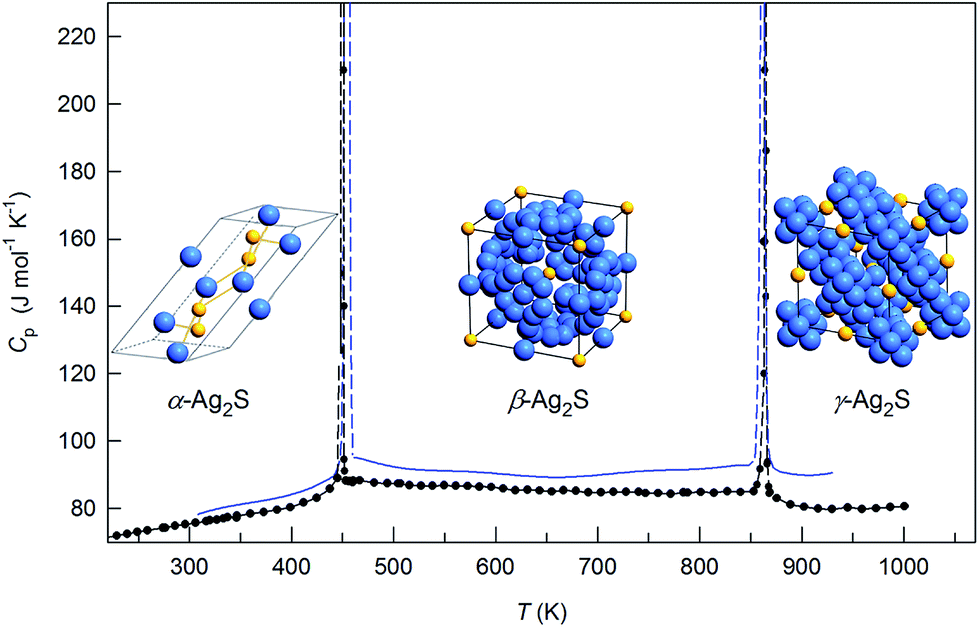 | ||
| Fig. 20 Heat capacity of silver sulfide nanopowder. For comparison, the heat capacity (●) of coarse-grained Ag2S170 is shown. The unit cells of α-Ag2S acanthite, β-Ag2S argentite and γ-Ag2S phase are shown in the temperature regions of existence of these phases. Reproduced from ref. 175 with permission of Springer. | ||
The main reason of variation of the lattice properties of nanocrystals in comparison with bulk substances is variation of the shape and boundaries of the phonon spectrum, i.e. change of the frequency distribution function of atomic vibrations.176
According to,178,179 waves can occur in nanoparticles whose length does not exceed the doubled maximum size of the particle D, i.e., λ ≤ 2D. Hence, on the side of low-frequency vibrations, the phonon spectrum is limited by a certain minimal frequency  , where ct is the velocity of propagation of transverse elastic vibrations (i.e., transverse velocity of sound). In bulk crystals, there is no limitation like this. Besides, the phonon spectrum is limited on the side of high frequencies.
Studies,176,177 took into consideration the restrictions of the phonon spectrum of the small particles and used the approach180 for the upper boundary ωmax of the phonon spectrum of small particles. They showed that the molar heat capacity of a model nanocrystalline substance with particles of a cubic shape with edges in length D can be presented as a function not only of the temperature T, but also of the size D of the small particle:
 | (9) |
The linear thermal expansion coefficient α(T) is related to heat capacity CV by the known relationship
 | (10) |
With allowance for eqn (9) and (10), the thermal expansion coefficient of nanocrystalline substance can be presented as
 | (11) |
Thus, the heat capacity and the thermal expansion coefficient of a nanocrystalline substance include an additional positive contribution as compared with the same properties of a coarse-grained (bulk) substance. Exactly this result was observed for the heat capacity and the thermal expansion coefficient of nanocrystalline and coarse-grained (bulk) Ag2S. The appearance of a positive contribution is due to the restriction of the phonon spectrum on the side of low and high frequencies.
According to,166 the reduction of the particle size in Ag2S is accompanied by enhancement of the anharmonicity of atomic vibrations. Anharmonicity results in enhanced phonon–phonon scattering, which reduces the thermal conductivity κ and increases the ZT of nanostructured Ag2S. This confirms the possibility of application of nanostructured Ag2S as a thermoelectric material that it was noted in study.58
5. Heteronanostructures based on Ag2S
Semiconductor–metal hybrid heteronanostructures may exhibit not only a combination of properties of the separate components but also further enhanced property tunability. It is supposed that, owing to synergetic effects, new improved properties will arise from the interactions between the metal and semiconductor.Among semiconductor–metal nanocomposites, the heteronanostructures based on Ag2S have attracted special attention and are very useful for manifold applications. Ag2S-based heteronanostructures can be used in infrared detectors, in resistance-switches and nonvolatile memory devices, and for bioimaging as biomarkers.2,5,16,43,48–50,181–183 According to,184,185 Ag2S-based heteronanostructures exhibit an excellent bactericidal effect against many types of bacteria. In recent years, Ag2S-based semiconductor–metal heterostructures have emerged as one of the leading materials for photocatalytic conversion of sunlight energy.186–188
Synthesis of Ag2S/M (M = Ag, Au, Pt, Pd, Os) heteronanostructures was studied in detail by Yang, Ying and co-authors.16,40,189,190 They developed a general scheme for transferring the transition metal ions from water to an organic medium using an ethanol-mediated route, which was extended to preparation of a variety of semiconductor/noble-metal heteronanostructures.
A room-temperature method was developed to first derive aqueous-dispersible Ag2S nanocrystals. Typically, C18H17K2O8PS2 salt was added to aqueous AgNO3 solution. The mixture was stirred for 1 h to form Ag-complexes, with subsequent prompt addition of aqueous Na2S solution, which resulted in Ag2S hydrosol being produced.40 Then, Ag2S nanocrystals were used as seeds for the formation of nanocomposites with different metals. By using 7 nm Ag2S nanocrystals, Na3Cit, and various noble-metal precursors at 378 K (for gold) and 383 K (for other noble metals), a set of Ag2S/M heteronanostructures were obtained, such as Ag2S/Au and Ag2S/Ag (Fig. 21), Ag2S/Pt, Ag2S/Os, and Ag2S/Pd. In the presence of Ag2S seeds, the metals nucleated preferentially on the existing Ag2S seeds rather than homogeneously.
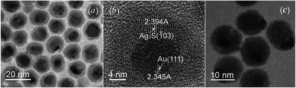 | ||
| Fig. 21 (a) TEM and (b) HRTEM images of Ag2S/Au heteronanostructures,188 and (c) TEM image of Ag2S/Ag heteronanostructures.16 | ||
Cation-exchange reactions can also be used to prepare heteronanostructures through the partial transformation of ionic nanocrystals.2
The chemical transformation of nanocrystalline solids has emerged as a very promising strategy for inorganic nanostructure synthesis. Among various chemical transformations, the cation-exchange reaction is especially interesting because it can alter the composition of the existing ionic nanocrystal by replacing the cations within the crystal lattice with a different metal ion.
The cation exchange at the nanoscale can transfer one material into another while retaining its morphology. If the exchange only takes place partially in the nanostructure, alloy or core–shell structures are formed. However, by carefully controlling the reaction, heterostructures may also be obtained. Alivisatos and co-authors191 gave an example of partial change of CdS nanorods into Ag2S to form CdS–Ag2S superlattices. CdS nanorods in toluene were added to a solution containing toluene, AgNO3 and methanol at very low temperature and then warmed to room temperature slowly to allow the replacement reaction. The lattice mismatch strains induced the spontaneous formation of periodic structures. The product showed an array of Ag2S quantum dots separated by confining regions of CdS. Such an array has potential applications as nanometer-scale optoelectronic devices.
Ag2S/ZnS heteronanostructures having a matchstick shape with Ag2S quantum dots as the heads and ZnS quantum rods as the stems were synthesized in study.192 These hybrid quantum rods were synthesized by a one-pot thermal decomposition method, and their size could be tuned by changing the ratio between the Ag–DDTC and zinc diethyldithiocarbamate (Zn[S2CN(C2H5)2]2 or Zn(DDTC)2) precursors. The diameter of the Ag2S head in the Ag2S/ZnS heterostructures was around 8.5 nm and the stem size was ∼7.8 × 35 nm when a 1:2 Ag(DDTC):Zn(DDTC)2 molar ratio was used in the synthesis. With an increased molar ratio of 2:1, the diameter of the Ag2S head in the heteronanostructures was about 4.5 nm and the stem size was ∼4 × 48 nm (Fig. 22). The Ag2S/ZnS heteronanostructures exhibited appealing PL in UV/blue and NIR regions. Later, Shen et al.43 modified the synthetic approach to demonstrate one-pot fabrication of Mn-doped Ag2S/ZnS quantum rods with multicolor PL in three wavelength regions (blue, orange, and NIR).
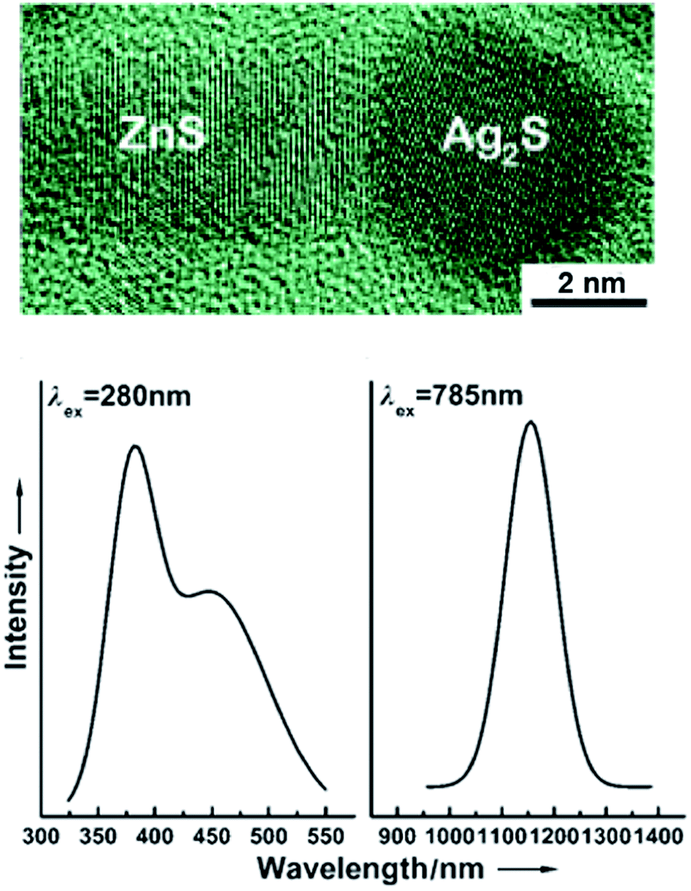 | ||
| Fig. 22 HRTEM image of an Ag2S/ZnS heteronanostructure and its UV/blue and NIR photo-luminescence at 280 and 785 nm, excitation, respectively. Reproduced from ref. 192 with permission from Wiley. | ||
A convenient room-temperature method for preparation of a new type of Ag2S/Ag heterodimers was devised in study.55 At first, monodisperse CdS colloidal nanospheres were synthesized through a modified polyol process (i.e., synthesis of a metal-containing compound in PEG). The CdS nanospheres were used as solid precursors for subsequent chemical transformation to Ag2S nanospheres via cation exchange and as a template for deposition of metallic silver. As a result, each Ag2S nanosphere was grown with a triangular prism of a Ag crystal, leading to formation of a novel type of asymmetric semiconductor/metal photosensitive heterodimers. According to,55 these Ag2S/Ag semiconductor/metal heterodimers exhibited remarkable bactericidal activity under visible-light illumination and may find future applications, including bacterial deactivation, bioimaging and sensing, as well as heterogeneous catalysis under ambient conditions.
According to study,193 mono-dispersed Ag2S@Ag hybrid nanocomposites exhibit superior adsorption performance for the removal of such organic contaminants as methyl blue and methyl orange from wastewater. Mono-dispersed Ag2S@Ag nanoparticles have been synthesized using laser ablation of bulk Ag targets in activated aqueous solution containing C2H5NS and hexadecyl trimethyl ammonium bromide.
Comparison of the advantages and disadvantages of the main methods for synthesis of Ag2S/Ag heteronanostructures is presented in Table 5.
| Method | Main reagentsa | Advantages | Disadvantages | Ref. |
|---|---|---|---|---|
| a PVP – polyvinylpyrrolidone (C6H9NO)n. | ||||
| Hydrothermal cation exchange | AgNO3, Na2S, Na3Cit, C18H17K2O8PS2 | Controllable size | Complicated process | 40, 189 and 190 |
| Cation exchange | Cd(NO3)2, AgNO3, Na3Cit, (NH2)2CS, C2H5OH, C3H6O, PVP | Controllable size | Complicated sequential process | 55 |
| Laser ablation | Ag, C2H5NS, C16H33N(CH3)3Br | Controllable size | Complicated operation, high cost | 193 |
| Hydrochemical deposition | AgNO3, Na2S, Na3Cit | Controllable size, non-toxic reagents, safety | Low yield | 195 and 200 |
Nonvolatile memory unit represents one of the most important components in state-of-the-art microelectronic/nanoelectronic devices and has been subject of intensive investigations in the past decades.16,48–50,181,194 Among different concepts memories, resistive switching memories, whose operation is primarily based on ion migrations that can result in reversible formation and breakage of a conductive filament in the sandwiched metal–insulator–metal structure, are particularly intriguing because they have a low production cost, offer reduced power consumption, and a switching rate as fast as semiconductor devices currently used and, in principle, can be made arbitrarily small. The Pt/Ag2S/Ag is an interesting structure exhibiting well-defined resistive switching behavior.181 For example, Aono and co-authors181,195 demonstrated basic logic gate operations and fabricated a 1 kbit nonvolatile memory chip based on a Pt/Ag2S/Ag heteronanostructure. Recently, they further clarified the rate-limiting processes determining the switching time in a Pt/Ag2S/Ag system, thus providing a deeper understanding toward the switching mechanism.196 Despite much recent progress, for future applications, an extended array of Ag2S/Ag resistive switches with smaller feature size as well as compatibility with conventional Si-based technology would be more favorable, but has not been realized.
The semiconductor/metal Ag2S/Ag heteronanostructures are interesting for the production of resistive switches and nonvolatile memory devices.
The electrical properties of Ag2S/Ag heteronanostructure of the heteronanowire type have been studied in work.48 An anodic aluminum oxide (AAO) template-assisted electrochemical strategy was used for synthesizing a Ag2S/Ag heteronanowire array. The porous AAO membrane was deposited partially with Ag nanowires, and then Ag2S nanowires were grown by electrochemical sulfurization. Liang et al.48 assumed that the main reason for the resistance-switching phenomenon in this Ag2S/Ag heteronanostructure was the creation and dissolution of a filament-like Ag conducting bridge.
Recently, authors of study194 reported the fabrication of an extended array of Ag2S/Ag nanodots with a density of 60 Gbit in−2, which was accomplished by sputtering Ag onto a Si substrate using an ultrathin porous AAO membrane as a shadow mask, followed by room-temperature sulfurization (Fig. 23). This resulted in the formation of a high density of Ag2S/Ag bilayer nanodots with a feature size of 45 nm.
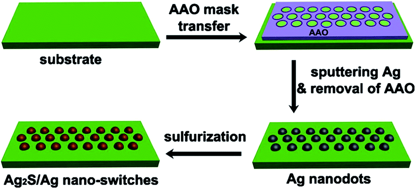 | ||
| Fig. 23 Schematic illustration of the fabrication of Ag2S/Ag nanodot resistive switch arrays (AAO is anodic aluminum oxide).194 | ||
The resistance switching behavior of an Ag/Ag2S/W nanoscale heterostructure of sandwich type was studied by Xu et al.49 To synthesize Ag2S, an Ag wire of diameter of 0.5 mm heated with S powder to 470 K for 30 min. The sulfidized Ag wire was scratched by an Ag wire so that some small pieces of Ag2S were transferred to the Ag wire. For observation, the Ag wire with the Ag2S tip-end was mounted on a high-resolution transmission electron microscope opposite the sharp tungsten W tip. Xu et al.49 directly observed the formation and breakage of a conducting pathway in a superionic solid electrolyte resistance nanoswitch with complete reproduction of its performance (Fig. 24). They found that the transition of semiconducting acanthite α-Ag2S into conducting argentite β-Ag2S took place at room temperature and only within a conductive pathway. The argentite not only formed part of the conducting channel but also provided the pathway for the migration of Ag+. In fact, the Ag+ could migrate only in the argentite phase and not in the acanthite α-Ag2S phase.
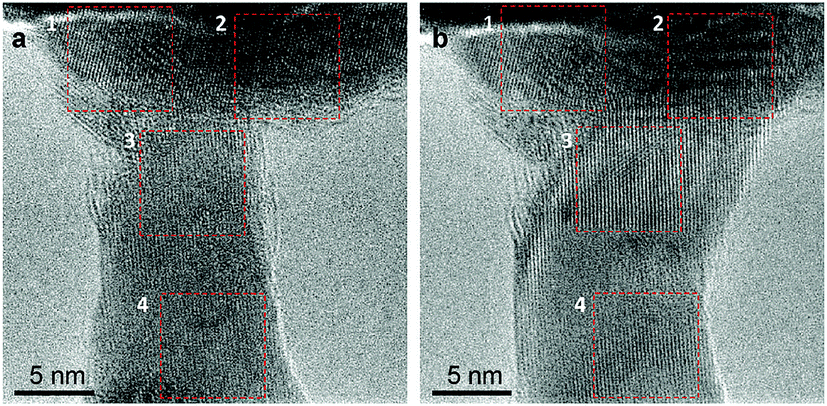 | ||
| Fig. 24 (a) Off- and (b) on-states of a narrow and thin Ag2S/Ag device regions. The Ag electrode is located on the top part of the image, and the W electrode is in the bottom part. When the device is switched from the off- to on-states, an area 1 has almost no change, the argentite appears in area 2, the argentite and Ag appear in area 3, and no changes are seen in area 4. Reproduced from ref. 49 with permission from ACS. | ||
In study,197 a wet chemical process was used for fabrication of Ag2S flat thin films on Ag electrodes utilized for an atomic Ag2S/Ag switch. A counter electrode made of Ag with a gap of ∼1 μm was fabricated using conventional UV-lithography on a Si substrate. The substrate with Ag was dipped into an aqueous solution of Na2S for sulfurization. As a result, Ag2S was formed on the Ag surface.
In study,50 the resistive switches Ag2S/Ag nanoclusters for memory cells were formed by sulfurization of melting-dispersed thin continuous Ag films. Ag nanocluster arrays were formed by thermal annealing of 10 nm-thick Ag films at 500 K during 40 min immediately after vacuum thermal evaporation. Low-temperature sulfurization in a H2S atmosphere in an airtight chamber was used to obtain Ag2S particles.
Gubicza et al.198 demonstrated stable resistive switchings in metallic Ag–Ag2S–Ag heteronanojunctions created by an scanning tunneling microscope (STM). An 80 nm-thick Ag layer was deposited onto a Si substrate followed by a 5 min sulfurization in a H2S atmosphere at 333 K. As a result, a 30 nm-thick stoichiometric Ag2S cap layer on the planar Ag electrode was obtained. Nanometer-scale junctions were created between the Ag2S surface and a mechanically sharpened Ag wire of 0.35 mm in diameter in STM geometry. According to,198 fast and highly integrable memory cells are the merits of lithographically designed Ag–Ag2S–Ag heteronanostructures.
The synthesis of multifunctional nanocomposite systems is of great interest. In particular, heteronanostructures such as Ag2S/Ag consisting of a semiconductor and a noble metal are very useful for various applications. This type of heterostructures that contain Ag and Ag2S nanowires or an Ag film with Ag2S/Ag nanoclusters are considered for the production of biosensors,183 resistive switches, and nonvolatile memory devices.48–50,194,197,199 The action of the resistive switch is based on the phase transformation between nonconducting α-Ag2S acanthite and superionic β-Ag2S argentite.
Hydrochemical deposition has been applied for the first time to the synthesis of Ag2S/Ag heteronanostructures in studies.136,200–203 Ag2S/Ag heteronanostructures have been synthesized by chemical deposition from aqueous solutions of AgNO3, Na2S, and Na3Cit with a reduced concentration of Na2S (CNa2S < CAgNO3/2). Synthesis was carried out under illumination of solutions by a light-emitting diode with a 450 nm wavelength and an irradiation intensity of 15 mW cm−2. Two processes take place simultaneously in such mixtures: formation of Ag2S and appearance of Ag nanoparticles as a result of photochemical reduction reaction (6) of Ag2+ by C6H5O73−. At certain synthesis conditions, Ag and Ag2S nanoparticles are united in Ag2S/Ag nanocomposites.
The scheme of deposition of Ag2S/Ag heteronanostructures from aqueous solutions of AgNO3, Na2S and Na3Cit, TEM and HRTEM images of Ag2S, Ag and Ag2S/Ag particles and their diffraction patterns, as well as EDX analysis of Ag2S, Ag particles and Ag2S/Ag heteronanostructures are shown in Fig. 25.
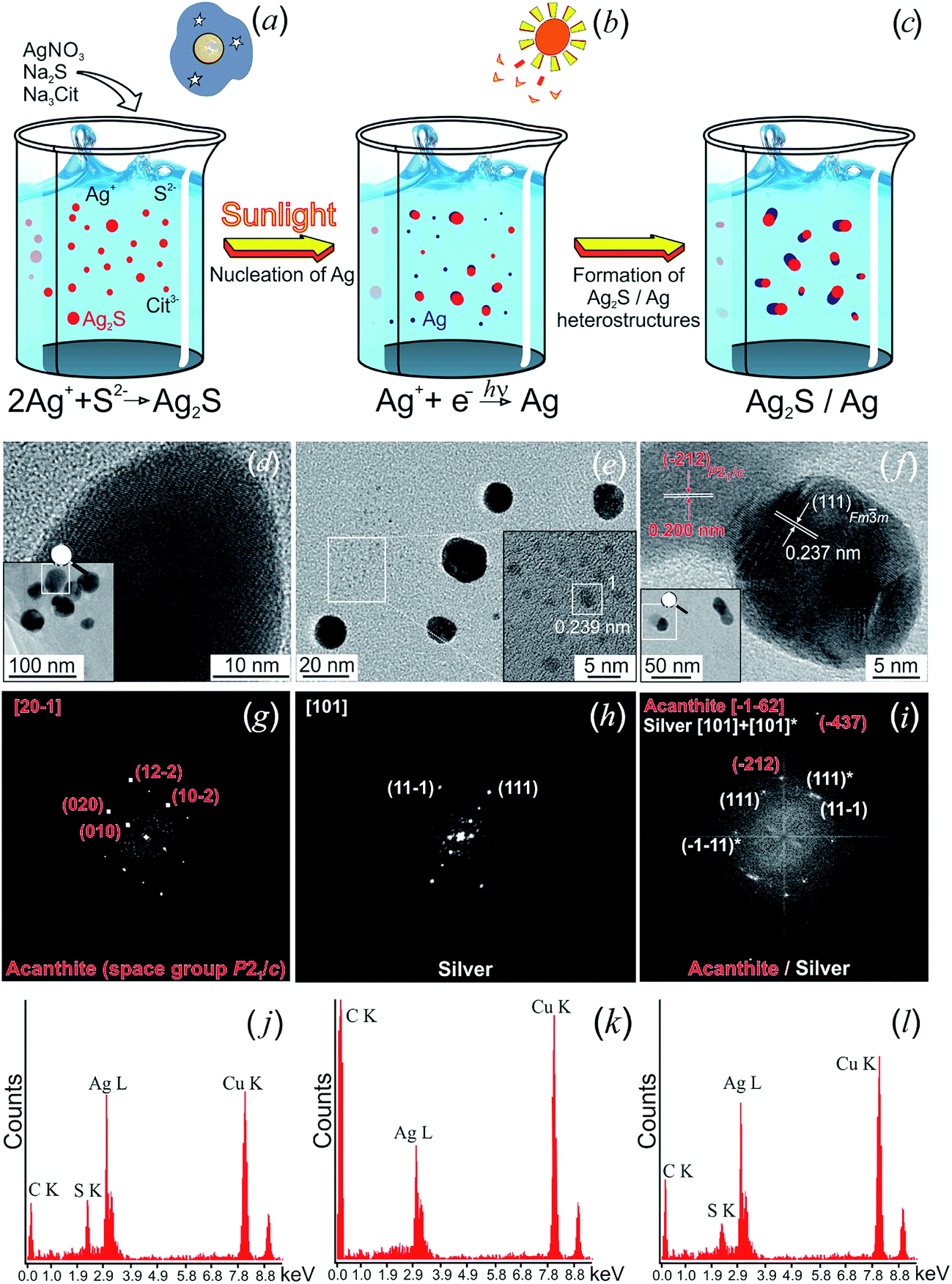 | ||
| Fig. 25 Hydrochemical bath deposition of Ag2S/Ag heteronanostructures. (First row) scheme of deposition. (Second row) TEM and HRTEM images of (d) Ag2S nanoparticles, (e) Ag nanoparticles, and (f) Ag2S/Ag heteronanostructures. (Third row) FFT patterns (g), (h), and (i) obtained from the (d), (e), and (f) HRTEM images, respectively. (Fourth row) EDX analysis of (j) Ag2S nanoparticle, (k) Ag nanoparticle, and (l) Ag2S/Ag heteronanostructure. Reproduced from ref. 200 with permission of Springer. | ||
Synthesis was carried out in a particular sequence. Briefly, a complexing agent was added to AgNO3 in the dark. Then, a solution of Na2S was poured into the prepared solution (Fig. 25a). As a result, deposition of Ag2S powder occurred. Then, the solution was irradiated with monochromatic light at wavelength 450 nm. In accordance with the photochemical reaction (6) C6H5O73− reduced the Ag+ to Ag nanoparticles in aqueous solutions (Fig. 25b). The reduction of Ag at the surface of Ag2S nanoparticles leads to the formation of Ag2S/Ag heteronanostructures (Fig. 25c).
The HRTEM images of deposited Ag2S, Ag and Ag2S/Ag particles are shown in Fig. 25d–f, respectively. In studies,136,200,201,203 the diffraction patterns (selected area of electron diffraction (SAED)) (Fig. 25g–i) of these particles were obtained by fast Fourier transformation (FFT) of their HRTEM images.
The observed set (Fig. 25g) of diffraction reflections and interplanar distances of Ag2S nanoparticles corresponded to monoclinic (space group P21/c) nanocrystalline acanthite α-Ag1.93S.148 The Ag nanoparticle (Fig. 25e) had a cubic (space group Fmm) structure with microtwinning in the direction of the [111] planes (Fig. 25h). Diffraction patterns (Fig. 25i) obtained by FFT of HRTEM images (Fig. 25f) of Ag2S/Ag heteronanostructures revealed reflections of monoclinic Ag2S and twinned reflections of cubic Ag.
According to the EDX results (Fig. 25j–l), the content of Ag and S in Ag2S nanoparticles was ∼86.3 ± 0.4 and ∼12.9 ± 0.1 wt% and corresponded to ∼Ag1.95–1.98S. Ag nanoparticles contained Ag only, and Ag2S/Ag heteronanostructure contained about 87.8 and 11.5 wt% of Ag and S, respectively.
The XRD pattern and HRTEM images of Ag2S/Ag heteronanostructures are shown in Fig. 26. Areas (1) and (3) correspond to Ag and Ag2S nanoparticles, respectively. The Ag nanoparticle clearly exhibited microtwinning in the direction of the [01−1] planes. Area (2) corresponded to that part of heteronanostructure where the Ag2S and Ag nanoparticles are in direct contact. Indeed, a set of spots (Fig. 26b) contains diffraction reflections of both phases: Ag2S and Ag. The interplanar distances for area (3) and the set of eight spots (Fig. 26c) corresponded to monoclinic (space group P21/c) α-Ag2S acanthite.
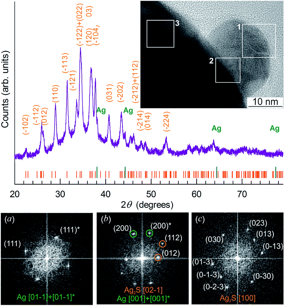 | ||
| Fig. 26 The XRD pattern and HRTEM image of Ag2S/Ag heteronanostructures. The long and short ticks on XRD patterns correspond to reflections of cubic metallic Ag and monoclinic Ag2S, respectively. The areas (1) and (3) isolated by a white square correspond to Ag and Ag2S, respectively. Area (2) corresponds to the region where the Ag2S and Ag nanoparticles are in direct contact. (a), (b), and (c) Selected areas of electron diffraction obtained by FFT of areas (1), (2), and (3) of heteronanostructure. Twinned reflections of silver are marked by *. Reproduced from ref. 200 with permission of Springer. | ||
The Ag2S/Ag heteronanostructures combine ionic and electronic conductors and can be used to create biosensors, resistive switches and nonvolatile memory devices.
Let us turn to a discussion of Ag2S/Ag heteronanostructures prepared by the hydrochemical deposition method.
A typical Ag2S/Ag heteronanostructure contained in the colloidal solution prepared from aqueous solutions of AgNO3, Na2S and Na3Cit is shown in Fig. 27 as an example. As can be seen, the Ag2S and Ag nanoparticles are in immediate contact. The Ag nanoparticle clearly exhibits microtwinning in the direction of the [111] planes. According to the EDX data, the nanoparticle contains only Ag. The interplanar distances observed for Ag2S nanoparticles correspond to monoclinic acanthite. The zone axis of the Ag2S nanoparticle matrix is [101]P21/c.
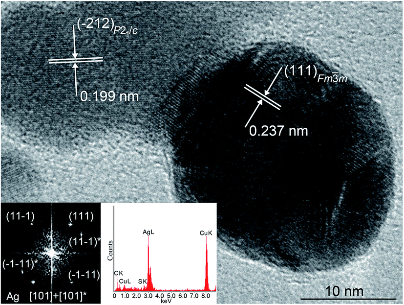 | ||
| Fig. 27 HRTEM image of Ag2S/Ag heteronanostructures. Monoclinic (space group P21/c) Ag2S nanoparticle with an α-Ag2S acanthite structure (upper left corner) is in direct contact with a cubic (space group Fmm) Ag nanoparticle. The electron diffraction pattern obtained by FFT of the HRTEM image of an Ag nanoparticle, and cumulative elemental EDX pattern of this Ag nanoparticle, are shown (lower left corner). Twinned reflections of silver are marked by *, zone axes are [101] + [101]*. Reproduced from ref. 136 with permission from Wiley. | ||
The resistive switches of Ag2S/Ag types consist of a superionic conductor located between two metal electrodes. In the case of Ag2S/Ag heterostructures, one of the electrodes is Ag, and the second electrode can be Pt, Au, Cu, or W. The conductivity of Ag was 6.3 × 10⁵ ohm−1 cm−1, that of the β-Ag2S argentite and α-Ag2S acanthite phases were about 1.6 × 10³ and only 2.5 × 10⁻³ ohm−1 cm−1 at room temperature,35 respectively. Thus, the conductivity of acanthite was 6 orders of magnitude lower than that for the argentite phase. It is, thus, reasonable to conclude that the conducting channel in Ag2S/Ag heterostructures can be made of a mixture of Ag and β-Ag2S argentite.
In studies,136,200–203 Ag2S/Ag heteronanostructures formed by Ag2S and Ag nanoparticles were produced by a simple method of hydrochemical bath deposition. Deposition of Ag2S/Ag heterostructures on a substrate coated with a thin conducting metallic layer will make it possible to form a structure that can work as a resistive switch. The action of the switch is based on the phase transformation of nonconducting α-Ag2S acanthite into β-Ag2S argentite exhibiting superionic conduction. The transition into a high-conduction state is due to abrupt disordering of the cationic sublattice. Authors of studies204,205 have shown that a high-conduction state of a crystal can be achieved by external electric field-induced “melting” of the cationic sublattice taking place without heating of the crystal. Such transformation occurring as a result of applied external electric field was confirmed with respect to nanocrystalline Ag2S in studies.49,50,194,199 The effect of an external electric field induced abrupt disordering, allowing the realization of the superionic state of Ag2S at room temperature. This opens up the possibilities for the practical use of materials based on Ag2S.
Authors of works200–203 studied preliminarily the switching processes in Ag2S/Ag heteronanostructures. For this purpose, a metallic Pt microcontact was supplied to Ag2S/Ag heteronanostructure and bias voltage was impressed so that the Ag electrode was charged positively. When positive bias voltage increased to 500 mV, the conduction of the heteronanostructure grew and the nanodevice transformed into the conducting state (i.e., the on-state). The bias back to negative values decreased the conduction and the nanodevice transformed into the off-state.
Fig. 28 displays a region of an Ag2S/Ag heteronanostructure where change of crystal structure at the transition from the off-state (Fig. 28a) to the on-state (Fig. 28b) can be observed. Using FFT of HRTEM images, authors of studies200,202,203 obtained the selected areas of electron diffraction (SAEDs) (Fig. 28c and d).
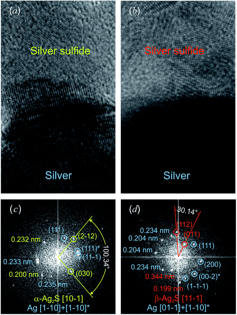 | ||
| Fig. 28 HRTEM images of the region of transition between Ag and Ag2S for the (a) off-state and (b) on-state of Ag2S/Ag heteronanostructures. The on-state arises as a result of applied external positive bias voltage to this Ag2S/Ag heteronanostructure. The Pt electrode is located on the top part of the image, and the Ag electrode is in the bottom part. Electron diffraction patterns (c) and (d) are obtained by FFT of HRTEM images (a) and (b), respectively. Reproduced from ref. 200 with permission of Springer. | ||
The electron diffraction pattern of an Ag2S/Ag heteronanostructure in the off-state is shown in Fig. 28c. This SAED contains (111), (11−1) spots and twinning reflection (111)* corresponding to cubic (space group Fmm) Ag, as well as (2−12) and (030) spots corresponding to monoclinic (space group P21/c) α-Ag2S acanthite. The observed angle of 100.3° between (2−12) and (030) spots of monoclinic acanthite coincided within the measurement error with the theoretical value 100.7°. Experimental angles between diffraction spots of cubic Ag coincided with the theoretical values.
Then, a positive bias was applied to the Ag2S/Ag heteronanostructure to turn it on. HRTEM images of an Ag2S/Ag heteronanostructure in the on-state and its selected electron diffraction patterns are presented in Fig. 28b and d, respectively. The electron diffraction pattern (Fig. 28d) contains two sets of spots corresponding to cubic (space group Fmm) Ag, and cubic (space group Imm) β-Ag2S argentite. The observed angle of 30.1° between the (011) and (112) spots of cubic β-Ag2S argentite coincides with the theoretical value of 30°.
Thus, the applied bias leads to the appearance of conducting β-Ag2S argentite instead of nonconducting α-Ag2S acanthite and the formation of conductive channel from argentite β-Ag2S and Ag.
The current–voltage I(V) characteristics of the resistive switches based on Ag2S/Ag heteronanostructures produced by different methods are presented in studies.48–50,194,199 As a rule, the bias voltage is from ±150 to ±500 mV. According to,49 the minimum energy barrier for an Ag cation jumping from one atomic site to the other is about 130 meV.
An I(V) characteristic of the resistive switch based on an Ag2S/Ag heteronanostructure produced by hydrochemical deposition in studies200,202,203 is shown in Fig. 29a. The schematic operation of this switch is shown in Fig. 29.
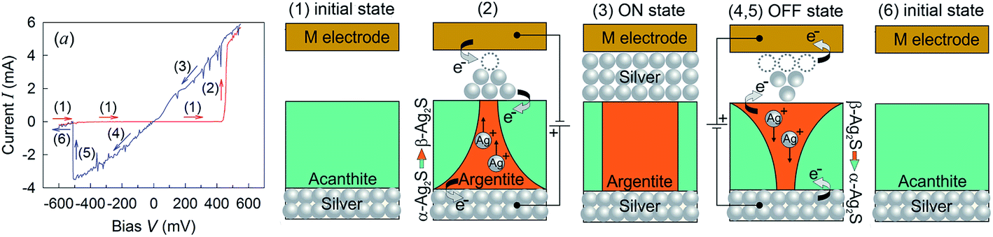 | ||
| Fig. 29 Generalized scheme of the operation of an Ag2S/Ag heteronanostructure-based switch: (a) typical current–voltage characteristic of the switching; (1) initial nonconducting state; (2) the appearance of a conductive channel upon the application of an external electric field that induces the transformation of acanthite α-Ag2S into argentite β-Ag2S; (3) work on-state with a continuous conductive channel formed from argentite β-Ag2S and Ag; (4, 5) off-state and breakdown of the conductive channel upon the application of negative bias and the transformation of argentite into initially acanthite; (6) initial nonconducting state after disappearance of the conductive channel and turning-off of the switch. M is the metal electrode. The numbers from 1 to 6 for different states of switching correspond to the order of the events on (a) current–voltage characteristics. Reprinted from ref. 202 with permission from Elsevier. | ||
The initial Ag2S phase was a nonconducting acanthite α-Ag2S (Fig. 29(1)). When a positive bias was applied, Ag+ started to move towards the negatively charged cathode M and were reduced to Ag during their transport. Simultaneously, the α-Ag2S phase transformed into superionic β-Ag2S argentite (Fig. 29(2)), and a continuous conductive channel was formed (Fig. 29(3)). The continuous conductive channel that was formed from argentite β-Ag2S and Ag was retained when the external field is turned off. This phenomenon can be considered to be a memory effect (Fig. 29(3)). If a negative (reverse) bias is applied to the switch, the Ag nanocrystals start dissolving in argentite, the Ag+ move to the anode, argentite transforms into the initial acanthite again, the conductive channel breaks down, and an off-state is realized (Fig. 29(4 and 5)). Because of the formation of nonconducting acanthite, the conductive channel disappears, the switch transforms into the initial state and is turned off (Fig. 29(6)). If positive bias is applied once again, the destroyed conductive channel is restored due to the appearance of argentite and the formation of Ag.
According to,49,50,202,203 the bias voltage which is sufficient to turn on and turn off the switch is from ±0.2 to ±10.0 V depending on the metal M used as the second electrode.
The UV-vis optical absorption spectra of colloidal solutions containing Ag2S/Ag composite nanoparticles200 contain a broad intensive absorption band in the region of ∼360 to 450 nm, which corresponds to Ag nanoparticles and is due to surface plasmon resonance (SPR).55,100,206,207 Also, the weakly diffused absorption peak observed at ∼312–320 nm corresponds to Ag2S nanoparticles.
Ag2S/Ag nanocomposites can be applied as promising biosensing probes. Ag nanoparticles can be used as biosensors owing to their unique SPR, which depends on the size and shape of particles.183,208,209 However, Ag nanoparticles are easily oxidized, which is why they should be protected. The combination of Ag nanoparticles and chemically stable Ag2S allows one to increase the stability of Ag nanoparticles and to use Ag2S/Ag nanocomposites and Ag@Ag2S core–shell structures for biosensing applications in the future.
According to,186,210 Ag2S/Ag heteronanostructures possess considerable antibacterial activity and can be used in biology and medicine. This agrees with data54,55,144 on the antibacterial activity of Ag2S colloidal solutions and nanopowders.
6. Conclusions and outlook
This review presented the major advances in the controlled synthesis of nanostructured Ag2S in the form of nanopowders, stable colloidal solutions, quantum dots, isolated nanoparticles with a protective shell, and heteronanostructures. Also, the main results on the study of crystal structure, nonstoichiometry and properties of nanostructured Ag2S were detailed.An increasing variety of semiconductor nanostructured Ag2S with various sizes and shapes can now be prepared. Along with the development of synthetic methods, the applications of nanostructured Ag2S have become wider.
Investigations over recent years have shown that nanostructured materials based on Ag2S are more effective than their bulk counterparts due to the following advantages: higher specific surface areas and more active sites for catalysis; longer cycle life; enhanced band gap of the semiconductor Ag2S phase; higher electric conductivity of high-temperature Ag2S phases; shorter path lengths for the transport of charge carriers (electrons and holes). Experimental studies of the quantum confinement effect of Ag2S quantum dots have shown that the exciton diameter of Ag2S is about 4 nm.
Synthesized forms of nanostructured Ag2S have several possible applications. First, stable Ag2S colloidal solutions and Ag2S quantum dots are suitable for biological and medical application as biomarkers because these solutions are non-toxic and do not contain hazardous substances. Ag2S quantum dots exhibit bright photoluminescence and excellent photostability. Therefore, Ag2S quantum dots of size less than 3–4 nm could be used for NIR applications in the biomedical field as luminophores or biomarkers. The creation of a protective shell on Ag2S quantum dots helps to prevent the agglomeration and growth of quantum dots and to retain their optical properties.
Nanocrystalline Ag2S powders can be used for production of electronic devices such as photovoltaic cells, photoconductors, and infrared detectors.
Ag2S/Ag heteronanostructures unite ionic and electronic conductors. A high-conducting state of such heteronanostructures can be induced by an external electric field without heating of this composite owing to phase transformation of nonconducting acanthite into argentite and the exhibition of superionic conduction. Ag2S/Ag heteronanostructures are intended for application in fast-acting resistive switches and nonvolatile memory devices. Also, Ag2S/Ag nanocomposites can be applied as promising biosensing probes and photocatalysts. Composite heteronanostructures based on Ag2S not only combine the properties of the individual nanocrystals, but also lead to new collective properties due to synergetic effects. Recent studies have shown that the synergetic effect can considerably enhance the properties of composite nanomaterials based on nanostructured Ag2S.
All the forms of nanostructured Ag2S possess significant potential antibacterial activity, and can be used as effective agents against asepsis and for disinfection.
Thus, recent advances have shown that nanostructured Ag2S possesses great possibilities for potential application in different areas, from optoelectronics to biomedicine, because of its unique physical and chemical properties and “nanosized” effects.
The exploration and development of new synthetic methods and techniques to prepare nanostructured Ag2S with better performance, and understanding of its structure-related properties, is an ongoing task for researchers.
Although the last decade has witnessed great progress in the synthesis of nanostructured Ag2S and its application, challenges still exist. The discussion below illustrates some of the challenges that scientists and technologists are facing in the synthesis and application of nanostructured Ag2S.
Stable colloidal solutions contain the finest Ag2S nanoparticles of size about 2–16 nm but the concentration of such nanoparticles is 0.01–0.02 mg mL−1 and rather small. That is why an important problem in the synthesis of different forms of nanostructured Ag2S remains the preparation of more concentrated colloidal solutions that retain their long-term stability and small size of nanoparticles.
Obtaining a narrow size distribution of synthesized Ag2S nanoparticles (i.e., the synthesis of uniform-sized nanoparticles) is another important challenge. Indeed, the synthesis of monodisperse Ag2S nanoparticles (with size variation <5%) is of key importance because the properties of the nanoparticles depend strongly on their sizes and uniformity.
One of the major challenges of using Ag2S quantum dots in electronics is the creation of large arrays of the quantum dots homogeneous in size and shape. The synthesized quantum dots are located on the substrate surface in a random way. For application in electronics, the prepared arrays of Ag2S quantum dots should be well ordered, preferably by self-organization, and should be compatible with optical devices and detectors. Another important problem facing Ag2S quantum dot arrays is improvement of the electric conductivity reduced by the organic ligands used in colloidal synthesis. Achieving the necessary performances of Ag2S quantum dot assemblies is an attainable aim in the next years.
Acknowledgements
This study was supported by the Russian Science Foundation (14-23-00025) via the Institute of Solid State Chemistry (Ural Branch) of the Russian Academy of Sciences.References
- Z. Zhuang, Q. Peng and Y. Li, Chem. Soc. Rev., 2011, 40, 5492–5513 RSC.
- M.-R. Gao, Y.-F. Xu, J. Jiang and S.-H. Yu, Chem. Soc. Rev., 2013, 42, 2986–3017 RSC.
- N. V. Hullavarad, S. S. Hullavarad and P. C. Karulkar, J. Nanosci. Nanotechnol., 2008, 8, 3272–3299 CrossRef CAS PubMed.
- S. I. Sadovnikov, A. I. Gusev and A. A. Rempel, Russ. Chem. Rev., 2016, 85, 731–758 CrossRef CAS.
- G. Xu, S. Zeng, B. Zhang, M. T. Swihart, K.-T. Yong and P. N. Prasad, Chem. Rev., 2016, 116, 12234–12327 CrossRef CAS PubMed.
- Semiconductor Nanostructures, ed. D. Bimberg, Springer, Berlin, Heidelberg, 2008, p. 357 Search PubMed.
- Nanostructured Materials for Advanced Technological Applications, ed. J. P. Reithmaier, P. Petkov, W. Kulisch and C. Popov, Springer, Netherlands, 2009, p. 547 Search PubMed.
- L. Kharghanian and A. Moghimi, Asian J. Chem., 2013, 25, 5904–5906 CAS.
- Nanostructured Semiconductors: From Basic Research to Applications, ed. P. Granitzer and K. Rumpf, CRC Press, New York, 2014, p. 700 Search PubMed.
- Metal Chalcogenide Nanostructures for Renewable Energy Applications, ed. A. Qurashi, Wiley, New York, 2015, p. 320 Search PubMed.
- A. P. Alivisatos, Science, 1996, 271, 933–937 CAS.
- N. N. Ledentsov, V. M. Ustinov, V. A. Shchukin, P. S. Kop’ev, Z. I. Alferov and D. Bimberg, Semiconductors, 1998, 32, 343–365 CrossRef.
- Z. I. Alferov, Rev. Mod. Phys., 2001, 73, 767–782 CrossRef CAS.
- C. Cui, X. Li, J. Liu, Y. Hou, Y. Zhao and G. Zhong, Nanoscale Res. Lett., 2015, 10, 431 CrossRef PubMed.
- D. S. Wang, C. H. Hao, W. Zheng, Q. Peng, T. H. Wang, Z. M. Liao, D. P. Yu and Y. D. Li, Adv. Mater., 2008, 20, 2628–2632 CrossRef CAS.
- J. Yang, E. H. Sargent, S. O. Kelley and J. Y. Ying, Nat. Mater., 2009, 8, 683–689 CrossRef CAS PubMed.
- Z. H. Sun, Z. Yang, J. H. Zhou, M. H. Yeung, W. H. Ni, H. K. Wu and J. F. Wang, Angew. Chem., Int. Ed., 2009, 48, 2881–2885 CrossRef CAS PubMed.
- A. M. Smith, M. C. Mancini and S. Nie, Nat. Nanotechnol., 2009, 4, 710–711 CrossRef CAS PubMed.
- P. Jiang, Z.-Q. Tian, C.-N. Zhu, Z.-L. Zhang and D.-W. Pang, Chem. Mater., 2012, 24, 3–5 CrossRef CAS.
- X. Wang, H. Huang, B. Liang, Z. Liu, D. Chen and G. Shen, Crit. Rev. Solid State Mater. Sci., 2013, 38, 57–90 CrossRef CAS.
- X. Shi, S. Zheng, W. Gao, W. Wei, M. Chem, F. Deng, X. Liu and Q. Xiao, J. Nanopart. Res., 2014, 16, 2741 CrossRef.
- S. Ummartyotin and Y. Infahsaeng, Renewable Sustainable Energy Rev., 2015, 55, 17–24 CrossRef.
- N. Kaur, S. Kaur, J. Singh and M. Rawat, J. Bioelectron. Nanotechnol., 2016, 1, 1–5 Search PubMed.
- S. Goel, F. Chen and W. Cai, Small, 2014, 10, 631–645 CrossRef CAS PubMed.
- J. Duan, H. Zhang, Q. Tang, B. He and L. Yu, J. Mater. Chem. A, 2015, 3, 17497–17510 CAS.
- R. C. Sharma and Y. A. Chang, Bull. Alloy Phase Diagrams, 1986, 7, 263–269 CrossRef CAS.
- H. Reye and H. Schmalzried, Z. Phys. Chem., 1981, 128, 93–100 CrossRef CAS.
- C. Wagner, J. Chem. Phys., 1953, 21, 1819–1827 CrossRef CAS.
- H. Rau, J. Phys. Chem. Solids, 1974, 35, 1553–1559 CrossRef CAS.
- G. Bonnecaze, A. Lichanot and S. Gromb, J. Phys. Chem. Solids, 1978, 39, 299–310 CrossRef CAS.
- G. Bonnecaze, A. Lichanot and S. Gromb, J. Phys. Chem. Solids, 1978, 39, 813–821 CrossRef CAS.
- A. V. Ditman and I. N. Kulikova, Zh. Fizich. Khimii, 1979, 53, 260–261 CAS , in Russian.
- K. Mitteilung, Z. Phys. Chem., 1980, 119, 251–255 CrossRef.
- M. K. van Doorselaer, J. Photogr. Sci., 1987, 35, 42–52 CrossRef CAS.
- P. Junod, Helv. Phys. Acta, 1959, 32, 567–600 CAS.
- P. Junod, H. Hediger, B. Kilchör and J. Wullschleger, Philos. Mag., 1977, 36, 941–958 CrossRef CAS.
- S. H. Ehrlich, J. Imaging Sci. Technol., 1993, 37, 73–91 CAS.
- S. Chang, Q. Li, X. Xiao, K. Y. Wong and T. Chen, Energy Environ. Sci., 2012, 5, 9444–9448 CAS.
- W. P. Lim, Z. Zhang, H. Y. Low and W. S. Chin, Angew. Chem., Int. Ed., 2004, 43, 5685–5689 CrossRef CAS PubMed.
- J. Yang and J. Y. Ying, Angew. Chem., Int. Ed., 2011, 50, 4637–4643 CrossRef CAS PubMed.
- G. X. Zhu and Z. Xu, J. Am. Chem. Soc., 2011, 133, 148–157 CrossRef CAS PubMed.
- A. I. Kryukov, A. L. Stroyuk, N. N. Zin’chuk, A. V. Korzhak and S. Y. Kuchmii, J. Mol. Catal. A: Chem., 2004, 221, 209–221 CrossRef CAS.
- S. Shen, Y. Zhang, Y. Liu, L. Peng, X. Chen and Q. Wang, Chem. Mater., 2012, 24, 2407–2413 CrossRef CAS.
- T. B. Nasrallah, H. Dlala, M. Amlouk, S. Belgacem and J. C. Bernede, Synth. Met., 2005, 151, 225–230 CrossRef.
- T.-Y. Hsu, H. Buhay and N. P. Murarka, in Millimeter Optics, ed. G. A. Tanton, SPIE Proc., 1980, vol. 259, pp. 38–45 Search PubMed.
- D. Karashanova, D. Nihtianova, K. Starbova and N. Starbov, Solid State Ionics, 2004, 171, 269–275 CrossRef CAS.
- L. Liu, S. Hu, Y.-P. Dou, T. Liu, J. Lin and Y. Wang, Beilstein J. Nanotechnol., 2015, 6, 1781–1787 CrossRef CAS PubMed.
- C. H. Liang, K. Terabe, T. Hasegawa and M. Aono, Nanotechnology, 2007, 18, 485202 CrossRef.
- Z. Xu, Y. Bando, W. Wang, X. Bai and D. Golberg, ACS Nano, 2010, 4, 2515–2522 CrossRef CAS PubMed.
- A. N. Belov, O. V. Pyatilova and M. I. Vorobiev, Adv. Nanopart., 2014, 3, 1–4 CrossRef.
- M. M. El-Nahass, A. A. M. Farag, E. M. Ibrahim and S. Abd-El-Rahman, Vacuum, 2004, 72, 453–460 CrossRef CAS.
- U. M. Jadhav, S. N. Patel and R. S. Patil, Res. J. Chem. Sci., 2013, 3, 69–74 CAS.
- P. Leidinger, R. Popescu, D. Gerthsen and C. Feldmann, Chem. Mater., 2013, 25, 4173–4180 CrossRef CAS.
- M. L. Pang, J. Y. Hu and H. C. Zeng, J. Am. Chem. Soc., 2010, 132, 10771–10785 CrossRef CAS PubMed.
- S. Xiong, B. Xi, K. Zhang, Y. Chen, J. Jiang, J. Hu and H. C. Zeng, Sci. Rep., 2013, 3, 2177 CrossRef PubMed.
- P. Jiang, C.-N. Zhu, Z.-L. Zhang, Z.-Q. Tian and D.-W. Pang, Biomaterials, 2012, 33, 5130–5135 CrossRef CAS PubMed.
- C. Li, Y. Zhang, M. Wang, Y. Zhang, G. Chen, L. Li, D. Wu and Q. Wang, Biomaterials, 2014, 35, 393–400 CrossRef CAS PubMed.
- C. Xiao, J. Xu, K. Li, J. Feng, J. Yang and Y. Xie, J. Am. Chem. Soc., 2012, 134, 4287–4293 CrossRef CAS PubMed.
- X. Zhang and L.-D. Zhao, J. Materiomics, 2015, 1, 92–105 CrossRef.
- M. Adelifard and R. Torkamani, J. Mater. Sci.: Mater. Electron., 2015, 26, 7554–7563 CrossRef CAS.
- Y. Zhao, C. Rinzler and A. Allanore, ECS J. Solid State Sci. Technol., 2017, 6, 3010–3016 CrossRef.
- S. Kashida, N. Watanabe, T. Hasegawa, H. Iida, M. Mori and S. Savrasov, Solid State Ionics, 2003, 158, 167–175 CrossRef CAS.
- L. Zhu, Z. Meng, G. Trisha and W.-C. Oh, Chin. J. Catal., 2012, 33, 254–2604 CrossRef CAS.
- A. Pourahmad, Superlattice Microst., 2012, 52, 276–287 CrossRef CAS.
- J. Jang, K. Cho, S. H. Lee and S. Kim, Mater. Lett., 2008, 62, 1438–1440 CrossRef CAS.
- L. Han, Y. Lv, A. M. Asiri, A. O. Al-Youbi, B. Tu and D. Y. Zhao, J. Mater. Chem., 2012, 22, 7274–7279 RSC.
- S. I. Sadovnikov and A. A. Rempel, Neorg. Mater., 2015, 51, 829–837 ( Inorg. Mater. , 2015 , 51 , 759–766 ) Search PubMed , in Russian.
- S. I. Sadovnikov, A. I. Gusev, E. Yu. Gerasimov and A. A. Rempel, Chem. Phys. Lett., 2015, 642, 17–21 CrossRef CAS.
- R. Chen, N. T. Nuhfer, L. Moussa, H. R. Morris and P. M. Whitmore, Nanotechnology, 2008, 19, 455604 CrossRef PubMed.
- W. Zhang, L. Zhang, Z. Hui, X. Zhang and Y. Qian, Solid State Ionics, 2000, 130, 111–114 CrossRef CAS.
- X. F. Qian, J. Yin, J. C. Huang, Y. F. Yang, X. X. Guo and Z. K. Zhu, Mater. Chem. Phys., 2001, 68, 95–97 CrossRef CAS.
- X. F. Qian, J. Yin, S. Feng, S. H. Liu and Z. K. Zhu, J. Mater. Chem., 2001, 11, 2504–2506 RSC.
- C. Xu, Z. Zhang and Q. Ye, Mater. Lett., 2004, 58, 1671–1676 CrossRef CAS.
- X. Lu, L. Li, W. Zhang and C. Wang, Nanotechnology, 2005, 16, 2233–2237 CrossRef CAS PubMed.
- V. B. Prabhune, N. S. Shinde and V. J. Fulari, Appl. Surf. Sci., 2008, 255, 1819–1823 CrossRef CAS.
- H. Meherzi-Maghraoui, M. Dachraoui, S. Belgacem, K. D. Buhre, R. Kunst, P. Cowache and D. Lincot, Thin Solid Films, 1996, 288, 217–223 CrossRef CAS.
- H. Li, J. X. Li, G. D. Li, D. P. Liu and J. S. Chen, Chem.–Eur. J., 2007, 13, 8754–8761 CrossRef PubMed.
- S. S. Dhumure and C. D. Lokhande, Mater. Chem. Phys., 1991, 28, 141–144 CrossRef CAS.
- L.-M. Lyu and M. H. Huang, Chem.–Asian J., 2013, 8, 1847–1853 CrossRef CAS PubMed.
- M. Lismont, C. A. Paez and L. Dreesen, J. Colloid Interface Sci., 2015, 447, 40–49 CrossRef CAS PubMed.
- Z. Li, L. Jia, Y. Li, T. He and X.-M. Li, Appl. Surf. Sci., 2015, 345, 122–126 CrossRef CAS.
- X. Peng, M. C. Schlamp, A. V. Kadavanich and A. P. Alivisatos, J. Am. Chem. Soc., 1997, 119, 7019–7029 CrossRef CAS.
- F. Pinaud, D. King, H. P. Moore and S. Weiss, J. Am. Chem. Soc., 2004, 126, 6115–6123 CrossRef CAS PubMed.
- G. Hota, S. Jain and K. C. Khilara, Colloids Surf., A, 2004, 232, 119–127 CrossRef CAS.
- D. O. Demchenko, R. D. Robinson, B. Sadtler, C. K. Erdonmez, A. P. Alivisatos and L.-W. Wang, ACS Nano, 2008, 2, 627–636 CrossRef CAS PubMed.
- A. Emamdoust, S. F. Shayesteh and M. Marandi, Pramana, 2013, 80, 713–721 CrossRef CAS.
- D. Gerion, F. Pinaud, S. C. Williams, W. J. Parak, D. Zanchet, S. Weiss and A. P. Alivisatos, J. Phys. Chem. B, 2001, 105, 8861–8871 CrossRef CAS.
- X. Gao, Y. Cui, R. M. Levenson, L. W. K. Chung and S. Nie, Nat. Biotechnol., 2004, 22, 969–976 CrossRef CAS PubMed.
- N. Tipcompor, S. Thongtem and T. Thongtem, J. Nanomater. (Hindawi), 2013, 2013, 970489 Search PubMed.
- J. Xiang, H. Cao, Q. Wu, S. Zhang, X. Zhang and A. A. R. Watt, J. Phys. Chem. C, 2008, 112, 3580–3584 CAS.
- Y. Yu, K. Zhang and S. Sun, Appl. Surf. Sci., 2012, 258, 7181–7187 CrossRef CAS.
- D. Deng, J. Xia, J. Cao, L. Qu, J. Tian, Z. Qian, Y. Gu and Z. Gu, J. Colloid Interface Sci., 2012, 367, 234–240 CrossRef CAS PubMed.
- M. S. Sadjadi and A. Khalilzadegan, Journal of Non-Oxide Glasses, 2015, 7, 55–63 Search PubMed.
- J. Zeng, Y. Zheng, M. Rycenga, J. Tao, Z. Y. Li, Q. Zhang, Y. Zhu and Y. Xia, J. Am. Chem. Soc., 2010, 132, 8552–8853 CrossRef CAS PubMed.
- L. Gutierrez, C. Aubry, M. Cornejo and J.-P. Croue, Langmuir, 2015, 31, 8865–8872 CrossRef CAS PubMed.
- S. d'Souza, P. Mashazi, J. Britton and T. Nyokong, Polyhedron, 2015, 99, 112–121 CrossRef.
- D. Philip, Spectrochim. Acta, Part A, 2010, 75, 1078–1081 CrossRef PubMed.
- R. Mendoza-Reséndez, A. Gómez-Treviño, E. D. Barriga-Castro, N. O. Núñez and C. Luna, RSC Adv., 2014, 4, 1650–1658 RSC.
- D. Ayodhya and G. Veerabhadram, J. Photochem. Photobiol., B, 2016, 157, 57–69 CrossRef PubMed.
- H.-Y. Yang, Y.-W. Zhao, Z.-Y. Zhang, H.-M. Xiong and S.-N. Yu, Nanotechnology, 2013, 24, 055706 CrossRef PubMed.
- A. C. C. Esteves and T. Trindade, Curr. Opin. Solid State Mater. Sci., 2002, 6, 347–353 CrossRef CAS.
- Q. Tang, S. M. Yoon, H. J. Yang, Y. Lee, H. J. Song, H. R. Byon and H. C. Choi, Langmuir, 2006, 22, 2802–2805 CrossRef CAS PubMed.
- T. X. Wang, H. Xiao and Y. C. Zhang, Mater. Lett., 2008, 62, 3736–3738 CrossRef CAS.
- C. L. Zhang, S. M. Zhang, L. G. Yu and Z. J. Zhang, Mater. Lett., 2012, 85, 77–80 CrossRef CAS.
- C. Burda, X. B. Chen, R. Narayanan and E. I. Sayed, Chem. Rev., 2005, 105, 1025–1102 CrossRef CAS PubMed.
- Y. Zhao, D. W. Zhang and W. F. Shi, Mater. Lett., 2007, 61, 3232–3234 CrossRef CAS.
- C. G. Xu, Z. C. Zhang and Q. Ye, Mater. Lett., 2004, 58, 1671–1676 CrossRef CAS.
- M. H. Chen and L. Gao, Mater. Lett., 2006, 60, 1059–1062 CrossRef CAS.
- H. J. Zhai and H. S. Wang, Mater. Res. Bull., 2008, 43, 2354–2360 CrossRef CAS.
- X. B. Wang, W. M. Liu, J. C. Hao, X. G. Fu and B. S. Xu, Chem. Lett., 2005, 34, 1664–1665 CrossRef CAS.
- L. H. Dong, Y. Chu and Y. Liu, J. Colloid Interface Sci., 2008, 317, 485–492 CrossRef CAS PubMed.
- Y. Fang, C. Bai and Y. Zhang, Chem. Commun., 2004, 804–805 RSC.
- Y. Z. Sun and B. B. Zhou, Mater. Lett., 2010, 64, 1347–1349 CrossRef CAS.
- Z. Zhuang, Q. Peng, X. Wang and Y. Li, Angew. Chem., Int. Ed., 2007, 46, 8174–8177 CrossRef CAS PubMed.
- R. G. Chaudhuri and S. Paria, J. Colloid Interface Sci., 2012, 369, 117–122 CrossRef PubMed.
- M. Y. Liu, Z. L. Xu, B. N. Li and C. M. Lin, Mater. Lett., 2011, 65, 555–558 CrossRef CAS.
- L. Y. Lv and H. Wang, Mater. Lett., 2014, 121, 105–108 CrossRef CAS.
- S. I. Sadovnikov, A. I. Gusev and A. A. Rempel, Superlattice Microst., 2015, 83, 35–47 CrossRef CAS.
- M. H. Huang, Y. Wu, H. Feick, N. Tran, E. Weber and P. Yang, Adv.Mater., 2001, 13, 113–117 CrossRef CAS.
- D. Wang, C. Hao, W. Zheng, Q. Peng, T. Wang, Z. Liao, D. Yus and Y. Li, Adv. Mater., 2008, 20, 2628–2632 CrossRef CAS.
- X. Wen, S. Wang, Y. Xie, X.-Y. Li and S. Yang, J. Phys. Chem. B, 2005, 109, 10100–10106 CrossRef CAS PubMed.
- C. H. Liang, K. Terabe, T. Hasegawa, R. Negishi, T. Tamura and M. Aono, Small, 2005, 1, 971–975 CrossRef CAS PubMed.
- S. C. Yan, H. T. Wang, Y. P. Zhang, S. C. Li and Z. D. Xiao, J. Non-Cryst. Solids, 2008, 354, 5559–5562 CrossRef CAS.
- S. Yan, K. Shen, X. Xu, Y. Shi, J. Wu and Z. Xiao, Synth. Met., 2011, 161, 1646–1650 CrossRef CAS.
- C.-S. Tan, C.-H. Hsiao, S.-C. Wang, P.-H. Liu, M.-Y. Lu, M. H. Huang, H. Ouyang and L.-J. Chen, ACS Nano, 2014, 8, 9422–9426 CrossRef CAS PubMed.
- M. Yarema, S. Pichler, M. Sytnyk, R. Seyrkammer, R. T. Lechner, G. Fritz-Popovski, D. Jarzab, K. Szendrei, R. Resel, O. Korovyanko, M. A. Loi, O. Paris, G. Hesser and W. Heiss, ACS Nano, 2011, 5, 3758–3765 CrossRef CAS PubMed.
- Y. Du, B. Xu, T. Fu, M. Cai, F. Li, Y. Zhang and Q. Wang, J. Am. Chem. Soc., 2010, 132, 1470–1471 CrossRef CAS PubMed.
- W. Cai, D. W. Shin, K. Chen, O. Gheysens, Q. Cao, S. X. Wang, S. S. Gambhir and X. Chen, Nano Lett., 2006, 6, 669–676 CrossRef CAS PubMed.
- J. Chen, T. Zhang, L. L. Feng, M. Zhang, X. Zhang, H. Su and D. Cui, Mater. Lett., 2013, 96, 224–227 CrossRef CAS.
- C. Siva, C. N. Iswarya, P. Baraneedharan and M. Sivakumar, Mater. Lett., 2014, 134, 56–59 CrossRef CAS.
- X. M. Hou, X. L. Zhang, W. Yang and Y. Liu, Mater. Res. Bull., 2012, 47, 2579–2583 CrossRef CAS.
- M. Shakouri-Arani and M. Salavati-Niasari, Spectrochim. Acta, Part A, 2014, 133, 463–471 CrossRef CAS PubMed.
- X. Wang, J. Zhuang, Q. Peng and Y. D. Li, Nature, 2005, 437, 121–124 CrossRef CAS PubMed.
- Y. Zhang, G. Hong, Y. Zhang, G. Chen, F. Li, H. Dai and Q. Wang, ACS Nano, 2012, 6, 3695–3702 CrossRef CAS PubMed.
- I. Hocaoglu, M. N. Çizmeciyan, R. Erdem, C. Ozen, A. Kurt, A. Sennaroglu and H. Y. Acar, J. Mater. Chem., 2012, 22, 14574–14681 RSC.
- S. I. Sadovnikov and A. I. Gusev, Eur. J. Inorg. Chem., 2016, 2016, 4944–4957 CrossRef CAS.
- C. S. Sunandana, Introduction to Solid State Ionics: Phenomenology and Applications, CRC Press, Baton Rouge, 2015, p. 529 Search PubMed.
- J. Yang and H. Liu, Metal-Based Composite Nanomaterials, Springer, Berlin, Heidelberg, 2015, p. 259 Search PubMed.
- T. V. Vinogradova, I. A. Glukhova, L. N. Maskaeva and V. F. Markov, Eur. Rev. Chem. Res., 2016, 10, 122–129 Search PubMed.
- P. Anastas and N. Eghbali, Chem. Soc. Rev., 2010, 39, 301–312 RSC.
- P. Patnaik, Dean's Analytical Chemistry Handbook, McGraw-Hill, New York, 2nd edn, 2004, Table 4.2, p. 1280 Search PubMed.
- P. C. Lee and D. Meisel, J. Phys. Chem., 1982, 86, 3391–3395 CrossRef CAS.
- S. I. Sadovnikov and A. A. Rempel, Patent No. 2572421 of Russian Federation, 2016, pp. 1–4.
- S. I. Sadovnikov, Y. V. Kuznetsova and A. A. Rempel, Nano-Structures & Nano-Objects, 2016, 7, 81–91 CAS.
- Y. Zhang, Y. Liu, C. Li, X. Chen and Q. Wang, J. Phys. Chem. C, 2014, 118, 4918–4923 CAS.
- S. I. Sadovnikov, Y. V. Kuznetsova, A. I. Gusev and A. A. Rempel, Patent No. 2600761 of Russian Federation, 2016, pp. 1–11.
- S. I. Sadovnikov, A. I. Gusev, E. Y. Gerasimov and A. A. Rempel, Neorg. Mater., 2016, 52, 487–492 ( Inorg. Mater. , 2016 , 52 , 441–446 ) CrossRef , in Russian.
- S. I. Sadovnikov, A. I. Gusev and A. A. Rempel, Phys. Chem. Chem. Phys., 2015, 17, 12466–12471 RSC.
- S. I. Sadovnikov, A. I. Gusev and A. A. Rempel, Patent No. 2603666 of Russian Federation, 2016, pp. 1–13.
- A. J. Frueh, Z. Kristallogr., 1958, 110, 136–144 CrossRef CAS.
- L. S. Ramsdell, Am. Mineral., 1943, 28, 401–425 CAS.
- P. Rahlfs, Z. Phys. Chem. B, 1936, 31, 157–194 Search PubMed.
- R. Sadanaga and S. Sueno, Mineral. J., 1967, 5, 124–148 CrossRef CAS.
- R. J. Cava, F. Reidinger and B. J. Wuensch, J. Solid State Chem., 1980, 31, 69–80 CrossRef CAS.
- T. Blanton, S. Misture, N. Dontula and S. Zdzieszynski, Powder Diffr., 2011, 26, 110–118 Search PubMed.
- C. Wang, X. Zhang, X. Qian, W. Wang and Y. Qian, Mater. Res. Bull., 1998, 33, 1083–1086 CrossRef CAS.
- V. Krylova and L. Samuolaitiene, Mater. Sci., 2013, 19, 10–14 CrossRef.
- L. Grocholl, J. Wang and E. G. Gillan, Mater. Res. Bull., 2003, 38, 213–220 CrossRef CAS.
- B. Kim, C.-S. Park, M. Murayama and M. F. Hochella, Environ. Sci. Technol., 2010, 44, 7509–7514 CrossRef CAS PubMed.
- G. A. Martínez-Castañón, M. G. Sánchez-Loredo, H. J. Dorantes, J. R. Martínez-Mendoza, G. Ortega-Zarzosa and F. Ruiz, Mater. Lett., 2005, 59, 529–534 CrossRef.
- L. V. Trandafilović, V. Djoković, N. Bibić, M. K. Georges and T. Radhakrishnan, Mater. Lett., 2010, 64, 1123–1126 CrossRef.
- S. I. Sadovnikov, A. I. Gusev and A. A. Rempel, Phys. Chem. Chem. Phys., 2015, 17, 20495–20501 RSC.
- S. I. Sadovnikov, A. I. Gusev and A. A. Rempel, Rev. Adv. Mater. Sci., 2015, 41, 7–19 Search PubMed.
- S. I. Sadovnikov, A. I. Gusev and A. A. Rempel, Dokl. Akad. Nauk, 2015, 464, 568–573 ( Dokl. Phys. Chem. , 2015 , 464 , 238–243 ) CrossRef , in Russian.
- S. I. Sadovnikov, A. V. Chukin, A. A. Rempel and A. I. Gusev, Fiz. Tverd. Tela, 2016, 58, 32–38 ( Phys. Solid State , 2016 , 58 , 30–36 ) Search PubMed , in Russian.
- S. I. Sadovnikov, A. I. Gusev, A. V. Chukin and A. A. Rempel, Phys. Chem. Chem. Phys., 2016, 18, 4617–4626 RSC.
- C. M. Perrott and N. H. Fletcher, J. Chem. Phys., 1969, 50, 2344–2350 CrossRef CAS.
- W. T. Thompson and S. N. Flengas, Can. J. Chem., 1971, 49, 1550–1563 CrossRef CAS.
- H. Okazaki and A. Takano, Z. Naturforsch., 1985, 40, 986–988 Search PubMed.
- F. Grønvold and E. F. Westrum, J. Chem. Thermodyn., 1986, 18, 381–401 CrossRef.
- https://summary.ccdc.cam.ac.uk/structure-summary?ccdc=1062400 .
- A. J. Frueh, Am. Mineral., 1961, 46, 654–660 CAS.
- A. I. Gusev, S. I. Sadovnikov, A. V. Chukin and A. A. Rempel, Fiz. Tverd. Tela, 2016, 58, 246–251 ( Phys. Solid State , 2016 , 58 , 251–257 ) Search PubMed , in Russian.
- K. Honma and K. Iida, J. Phys. Soc. Jpn., 1987, 56, 828–1836 CrossRef.
- S. I. Sadovnikov and A. I. Gusev, Phys. Solid State, 2017, 59, 1863–1870 Search PubMed.
- S. I. Sadovnikov and A. I. Gusev, J. Alloys Compd., 2014, 610, 196–202 CrossRef CAS.
- S. I. Sadovnikov and A. I. Gusev, Fiz. Tverd. Tela, 2014, 56, 2274–2278 ( Phys. Solid State , 2014 , 56 , 2353–2358 ) Search PubMed , in Russian.
- A. I. Gusev and A. A. Rempel, Nanocrystalline Materials, Cambridge Intern, Science Publ., Cambridge, 2004, p. 351 Search PubMed.
- Y. I. Petrov, Physics of Small Particles, Nauka, Moscow, 1982, p. 360, in Russian Search PubMed.
- E. W. Montrol, J. Chem. Phys., 1950, 18, 183–185 CrossRef.
- K. Terabe, T. Hasegawa, T. Nakayama and M. Aono, Nature, 2005, 433, 47–50 CrossRef CAS PubMed.
- B. G. Kumar, B. Srinivas, M. D. Prasad and K. Muralidharan, J. Nanopart. Res., 2015, 17, 325 CrossRef.
- B. Liu and Z. Ma, Small, 2011, 7, 1587–1592 CrossRef CAS PubMed.
- C. Marambio-Jones and E. M. V. Hoek, J. Nanopart. Res., 2010, 12, 1531–1551 CrossRef CAS.
- X. Ma, Y. Zhao, X. Jiang, W. Liu, S. Liu and Z. Tang, ChemPhysChem, 2012, 13, 2531–2535 CrossRef CAS PubMed.
- R. Costi, A. E. Saunders and U. Banin, Angew. Chem., Int. Ed., 2010, 49, 4878–4897 CrossRef CAS PubMed.
- N. Mishra, J. Lian, S. Chakrabortty, M. Lin and Y. Chan, Chem. Mater., 2012, 24, 2040–2046 CrossRef CAS.
- S. K. Dutta, S. K. Mehetor and N. Pradhan, J. Phys. Chem. Lett., 2015, 6, 936–944 CrossRef CAS PubMed.
- J. Yang and J. Y. Ying, Chem. Commun., 2009, 3187–3189 RSC.
- J. Yang, J. Y. Lee and J. Y. Ying, Chem. Soc. Rev., 2011, 40, 1672–1696 RSC.
- R. D. Robinson, B. Sadtler, D. O. Demchenko, C. K. Erdonmez, L. W. Wang and A. P. Alivisatos, Science, 2007, 317, 355–358 CrossRef CAS PubMed.
- S. Shen, Y. Zhang, L. Peng, Y. Du and Q. Wang, Angew. Chem., Int. Ed., 2011, 50, 7115–7118 CrossRef CAS PubMed.
- H. Zhang, M. Chen, D. M. Wang, L. Xu and X. D. Liu, Opt. Mater. Express, 2016, 6, 2573–2583 CrossRef.
- D. Wang, L. Liu, Y. Kim, Z. Huang, D. Pantel, D. Hesse and M. Alexe, Appl. Phys. Lett., 2011, 98, 243109 CrossRef.
- S. Kaeriyama, T. Sakamoto, H. Sunamura, M. Mizuno, H. Kawaura, T. Hasegawa, K. Terabe, T. Nakayama and M. Aono, IEEE J. Solid-State Circuits, 2005, 40, 168–186 CrossRef.
- A. Nayak, T. Tamura, T. Tsuruoka, K. Terabe, S. Hosaka, T. Hasegawa and M. Aono, J. Phys. Chem. Lett., 2010, 1, 604–608 CrossRef CAS.
- H. Tanaka, T. Akai, D. Tanaka and T. Ogawa, e-J. Surf. Sci. Nanotechnol., 2014, 12, 185–188 CrossRef.
- A. Gubicza, D. Z. Manrique, L. Pósa, C. J. Lambert, G. Mihály, M. Csontos and A. Halbritter, Sci. Rep., 2016, 6, 30775 CrossRef CAS PubMed.
- M. Morales-Masis, S. J. Molen, W. T. Fu, M. B. Hesselberth and J. M. Ruitenbeek, Nanotechnology, 2009, 20, 095710 CrossRef CAS PubMed.
- S. I. Sadovnikov and A. I. Gusev, J. Nanopart. Res., 2016, 18, 277 CrossRef.
- A. I. Gusev and S. I. Sadovnikov, Fiz. Tekh. Poluprovodn., 2016, 50, 694–699 ( Semiconductors , 2016 , 50 , 682–687 ) Search PubMed , in Russian.
- A. I. Gusev and S. I. Sadovnikov, Mater. Lett., 2017, 188, 351–354 CrossRef CAS.
- S. I. Sadovnikov and A. I. Gusev, Biointerface Res. Appl. Chem., 2016, 6, 1797–1804 Search PubMed.
- Y. I. Kharkats, Fiz. Tverd. Tela, 1981, 23, 2190–2192 CAS , in Russian.
- Y. Y. Gurevich and Y. I. Kharkats, Usp. Fiz. Nauk, 1982, 136, 693–728 ( Phys.-Usp. , 1982 , 25 , 257–276 ) CrossRef CAS , in Russian.
- A. Henglein, Ber. Bunsenges. Phys. Chem., 1997, 101, 1562–1572 CrossRef CAS.
- Y. A. Krutyakov, A. A. Kudrinskiy, A. Y. Olenin and G. V. Lisichkin, Usp. Khim., 2008, 77, 242–269 ( Russ. Chem. Rev. , 2008 , 77 , 233–257 ) Search PubMed , in Russian.
- M. Hu, J. Y. Chen, Z. Y. Li, L. Au, G. V. Hartland, X. D. Li, M. Marquez and Y. N. Xia, Chem. Soc. Rev., 2006, 35, 1084–1094 RSC.
- S. P. Song, Q. Yu, Y. He, Q. Huang, C. H. Fan and H. Y. Chen, Chem. Soc. Rev., 2010, 39, 4234–4243 RSC.
- J. Yang and H. Liu, Metal-Based Composite Nanomaterials, Springer, Cham, Heidelberg, Dordrecht, London, 2015, ch. 4, pp. 93–114 Search PubMed.
| This journal is © The Royal Society of Chemistry 2017 |