 Open Access Article
Nanocellulose-based foams and aerogels: processing, properties, and applications
Nathalie
Lavoine
 and
Lennart
Bergström
 *
*
Department of Materials and Environmental Chemistry, Stockholm University, Svante Arrhenius väg 16C, SE-106 91 Stockholm, Sweden. E-mail: lennart.bergstrom@mmk.su.se
First published on 30th May 2017
Abstract
Nanocellulose is a renewable and biocompatible nanomaterial with a high strength low density and tunable surface chemistry. This review summarizes the main processing routes and significant properties of nanocellulose-based foams and aerogels. Challenges, such as how to produce long-term stable wet foams or how to avoid structural collapse of the material during solvent removal using e.g. supercritical drying, are discussed. Recent advances in the use of ice templating to generate iso- or anisotropic foams with tunable mechanical and thermal properties are highlighted. We illustrate how the porous architecture and properties of nanocellulose-based foams and aerogels can be tailored for applications in e.g. thermal insulation and energy storage.
1. Introduction
Cellulose is a homopolysaccharide consisting of a linear chain of linked anhydroglucose units (AGU).1 The three hydroxyl groups on each AGU enable the cellulose chains to assemble with each other, determining e.g. the formation of fibrillar and semicrystalline species.2 Individual cellulose molecules are brought together into larger units, called elementary fibrils or microfibrils, which have a diameter of 3–4 nm and a length estimated to be over 1–2 μm. Each microfibril is composed of nano-sized and highly crystalline rod like fragments, referred to as cellulose nanocrystals (CNC).3 The microfibrils are packed into larger units, referred to as macrofibrils, with diameters ranging from 15 to 60 nm, which are in turn assembled into the familiar cellulose fibre (diameters 20–50 μm; lengths 1–4 mm). Cellulose nanofibrils (CNF) is a term commonly used to denote both the microfibrils and the macrofibrils.4Nanocellulose in the form of CNC and CNF has been the focus of a significant research interest during the last two decades. Nanocellulose is an abundant and renewable nanomaterial that combines a low density, high strength and flexibility with chemical inertness and possibility to modify the surface chemistry.5 The first stable colloidal suspension of CNC was produced in 1950, by Rånby and Ribi via acid hydrolysis of wood and cotton cellulose.6 Sulphuric acid is commonly used for producing sulphonated CNC,7 although CNC with other surface groups have been produced by hydrolyses with hydrochloric,8,9 phosphoric,10 hydrobromic,11 and phosphotungstic12 acids. The geometrical dimensions of CNC vary with the cellulosic source (cotton, ramie, tunicate, bacterial cellulose, softwood pulp, microcrystalline cellulose, etc.); but typically, the width is a few nanometres and lengths range from tenth nanometres to several micrometres. More information can be found in recent reviews.1,13
The production of CNF often requires chemical (carboxymethylation,14 carboxylation,15 quaternization,16etc.) or enzymatic17 pretreatments to be carried out prior to mechanical treatment. The CNF dimensions depend on the processing conditions and possible post-treatments such as chemical modification or fractionation.18 CNF have typically a diameter of 3–50 nm and a length of a few micrometres.
While early work on nanocellulose-based materials primarily focused on reinforced nanocomposites,19–22 a broad range of applications are today being investigated, including e.g. food-packaging,23,24 coatings,25 biomedical,26,27 and printed electronics28 devices. Reviews on the production methods of nanocelluloses,18 their rheology,29 barrier properties,4 chemical modifications2,30 or self-assembly3 are available for the interested readers.
The research interest in nanocellulose-based foams and aerogels is recent but rapidly growing. The combination of an ultralow density, tunable porous architecture and outstanding mechanical properties makes them of interest for a wide range of applications including e.g. biomedical scaffolds, thermal insulation and devices for storage and generation of energy.
This review aims to describe and discuss the processing, properties, and applications of nanocellulose-based foams and aerogels and highlights challenges that need to be overcome to enable the production of foams and aerogels with tailored properties for novel applications.
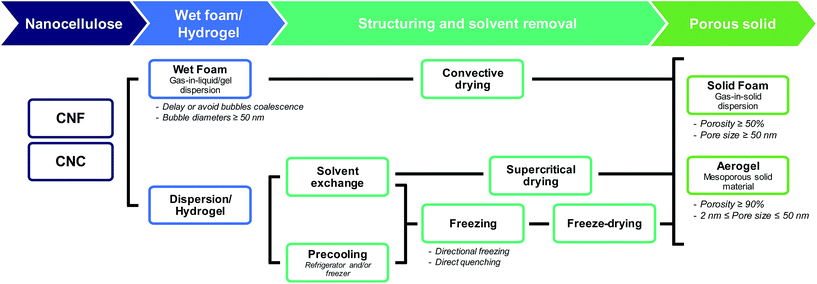
The terms “foam” and “aerogel” are commonly used interchangeably to describe nanocellulose-based porous materials. Previous reports have defined a (nanocellulose-based) aerogel as “a highly porous solid of ultra-low density and with nanometric pore sizes formed by replacement of liquid in a gel with gas”.31 Foams are usually more broadly defined, commonly referred to as “solid porous materials with micrometric pore sizes”.32 Throughout this review, when referring to nanocellulose-based foams or aerogels, we will then use the following definitions (Fig. 1):
– A nanocellulose(-based) foam is a multi-phase porous material with a porosity larger than 50% in which gas (e.g. air) is dispersed in a liquid, solid or hydrogel. The diameter of the bubbles (or the pore size) is usually larger than 50 nm.
– A nanocellulose(-based) aerogel is a mesoporous solid material (i.e. pore size in the range 2–50 nm) of high porosity (>90%).
2. Processing: from nanocellulose-based dispersions to porous solids
Processing of nanocellulose-based foams and aerogels involves two main steps (Fig. 1): (i) preparation of a gel or wet foam from a dispersion, and (ii) removal of the solvent by evaporation (oven drying), freeze drying, and supercritical drying preceded by solvent exchange. Fig. 1 also shows that foams can be structured directly from the dispersion by e.g. freezing of the solvents.2.1. Preparation and stability of nanocellulose-based wet foams/gels
Gas bubbles can be introduced into a nanocellulose-based aqueous dispersion by either vigorous stirring or shaking (the so called Bartsch method), by pouring (the Ross-Miles method)33 or sparging, i.e. by bubbling air into the dispersion (the Bikerman method).34 Gas bubbles can also be created by desorption or decomposition of added compounds, so called foaming agents.35Coalescence, partitioning and creaming of the inherently unstable gas bubbles need to be avoided or delayed to yield wet foams that are stable over a sufficient time. Foams drain, coarsen, and finally collapse when the films between the bubbles rupture.36 More details on foam stability mechanisms can be found in reviews of e.g. Lam et al.,37 Hunter et al.,38 Kaptay,39,40 and Fameau et al.41
Surfactants are frequently used to stabilize wet foams.36 Adsorption of surfactants to the air–water interface reduces the interfacial surface tension, can induce a disjoining pressure and improve the rigidity of the interfacial film. Most surfactant-stabilized foams, however, show a limited stability due to bubble disproportionation and coalescence caused by surfactant desorption.42 Adsorption of particles to the air–water interface to form the so called Pickering foams has been shown to result in wet foams with a very high stability (Fig. 2).43Eqn (1) describes the energy required to remove adsorbed spherical particles from an interface38 (here, air/water interface):
ΔG = πR2γAW(1 ± cos![[thin space (1/6-em)]](https://www.rsc.org/images/entities/char_2009.gif) θ)2 θ)2 | (1) |
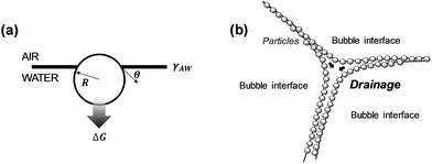 | ||
| Fig. 2 Particle-stabilized foams: (a) particle at an air/water interface, (b) particle-stabilized foam lamella (adapted from Hunter et al.38). | ||
Thinning of the foam lamella by drainage and evaporation increases the probability of film rupture and bubble coalescence. The particle size, contact angle, and surface coverage have a strong influence on the foam stability.44 Smaller particles delay or eliminate coalescence more efficiently that larger and/or flocculated particles.37
Anisotropic particles with a high aspect ratio, such as nanocellulose, are expected to stabilize wet foams more efficiently than spherical particles, because of the higher surface coverage and the entangled particle network formed around the gas bubbles.45
Wet nanocellulose-based foams that displayed long-term stability have been obtained by vigorous stirring of an aqueous dispersion of TEMPO-oxidized CNF and a non-ionic surfactant (Fig. 3a).42 The stability of the CNF/surfactant foams after heating was improved by reinforcing the CNF network by slow release of calcium ions.42
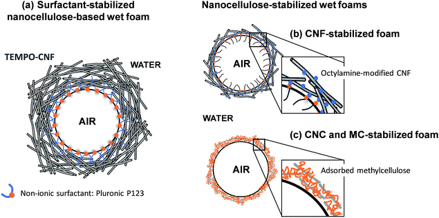 | ||
| Fig. 3 Wet nanocellulose-based foams stabilized by (a) a non-ionic surfactant,42 (b) partially hydrophobic CNF44 and (c) methylcellulose and CNC.46 | ||
Cervin et al.44,45 succeeded in forming stable CNF wet foams after adsorbing either octylamine or decylamine (two amine-functionalized surfactants) onto the CNF surface (Fig. 3b). The partially hydrophobic CNF adsorbed onto the air–water interface and promoted the formation of a thick entangled CNF layer onto the gas bubble surface. Cervin et al.45 showed that foams with higher stability were obtained when only 1/3 of the total charges of the CNF was screened by octylamine, compared to foams where 3 times more octylamine was added, corresponding to a 1-to-1 charge ratio. This suggests that the electrostatic component of the disjoining pressure also plays a role in the foam stability; indeed, increasing the salt concentration decreased the wet foam stability.45 Hence, while increasing the hydrophobicity of the nanocellulose particles promotes accumulation of CNF at the air/water interface, it is also essential to maintain a sufficient charge density on the surface of the modified particles to prevent flocculation and induce a repulsive disjoining pressure.37
A recent report described a straightforward procedure to produce aqueous wet foams based on unmodified CNC and methylcellulose (MC) (Fig. 3c).46 It was suggested that MC accumulated at the air/water interface and that adsorption of CNC to MC stabilized the interface and inhibited MC desorption. The MC/CNC-foams displayed a good long-term stability, also at elevated temperatures.46
Porous materials have also been prepared from Pickering water-in oil emulsions by polymerization47 or crosslinking of the continuous phase. Removal of the aqueous phase by e.g. freeze-drying48 resulted in dry foams where the porosity and pore size distribution were a replica of the initial emulsion droplets.
Finally, nanocellulose (hydro)gels can simply be prepared by physical entanglement e.g. by increasing the solid content of the aqueous nanocellulose dispersions,31 or by reducing the colloidal stability by e.g. changing the pH.49
2.2. Preparation of solid foams and aerogels
The main challenge in the production of nanocellulose-based porous solids is to maintain the porous structure during solvent removal. Evaporation of water from a porous material produces capillary pressure-induced stresses50 that can deform the pores and result in warping and collapse or cracking.Different drying techniques have been developed to avoid deformation or collapse of the porous network during solvent removal (Table 1). Nanocellulose-based porous solids have so far been produced using two main solvent-removal processes: (i) supercritical drying and (ii) ice sublimation; the latter being often combined with ice templating (IT).
| Feedstock | Processing | Porous solids | Ref | ||||
|---|---|---|---|---|---|---|---|
| Nanocellulosea | Matrix/fillers | Post-modification | Pre-stepc | Freezing | Dryingc | ||
| a Carboxymethy-CNF, Enzy-CNF, CHO-CNF, TEMPO-CNF, and Holo-CNF refer to carboxymethylated, enzymatic-pre-treated, aldehyde-modified, TEMPO-oxidized, and holocellulose CNF, respectively. BNC refers to bacterial nanocellulose. b GA = gluconic acid; PEI = polyethylenimine; PAH = poly(allylamine hydrochloride); PAA = polyacrylic acid; CNT = carbon nanotubes; GO = graphene oxide; BA = boric acid; PE resin = polyamide epichlorohydrin resin; MTMOS = methyltrimethoxysilane; TEOS = tetraethylorthosilicate; TMCS = trimethylchlorosilane; MMT = montmorillonite clay; VTMS = vinyltrimethoxysilane. c SE = solvent exchange (usually from water to either tert-butanol or ethanol); FD = freeze-drying; DQ = direct quenching. | |||||||
| Carboxymethy-/TEMPO-CNF | Octyl-/decylamine | — | Mechanical stirring | — | Oven | Foam | 44, 45 and 61 |
| TEMPO-CNF | Surfactant, CaCO3, GAb | 42 | |||||
| CNC | Methylcellulose | (Oil bath) | 46 | ||||
| Neat/modified CNC | — | Stirring; freezer; SE | Supercritical drying | Aerogel | 53 and 65 | ||
| BNC | SE | 54 and 69 | |||||
| Enzy-CNF | Stearoyl grafting | 70 | |||||
| TEMPO-CNF | — | 49 and 63 | |||||
| TEMPO-CNF | — | —/SE | DQ liquid N2 | FD | Foam | 49 | |
| CNF | — | DQ liquid N2/ethanol | 71 | ||||
| Enz-/Holo-CNF | Starch | Fridge/freezer | Freezer | 72 | |||
| Xyloglucan | DQ liquid N2 | 31, 73 and 74 | |||||
| Enz-/TEMPO-CNF | — | DQ in various liquid solvents (e.g. acetone) | 32 | ||||
| TEMPO-CNF | Stirring at −18°C | DQ liquid butyl acetate | |||||
| TEMPO-/CHO-CNF | Octylamine | — | DQ liquid N2 | 61 | |||
| TEMPO-CNF | PEIb | 75 | |||||
| CNC | — | DQ liquid N2/ethanol | |||||
| CNC | Polyvinyl alcohol | Freezer/DQ liquid N2 | 76 | ||||
| BNC | Zinc oxide | SE | FD | 77 | |||
| Enz-CNF | Starch | Fridge | Freezer | 78 and 79 | |||
| Enz-CNF | Starch | — | Fridge | Dry ice CO2 plate | FD | Foam | 78 and 79 |
| Freeze-casting | |||||||
| TEMPO-CNF/CNC | GOb, Sepiolite, BAb | — | 60 and 80 | ||||
| TEMPO-CNF | GOb or lignin/hemicellulose or VTMSb | — | — | FD | 81 | ||
| CNF | — | Fluorosilanes/TiO2 | — | FD | FD | Foam | 82–84 |
| PE resinb | — | Freezer/liquid N2 Spray | FD + oven | 85 and 86 | |||
| Soy protein | Fridge | Freezer | FD | 87 | |||
| CNTb | — | DQ liquid N2/propane | FD | 88 | |||
| — | Palmitoyl | SE | FD | 89 and 90 | |||
| MTMOSb | DQ liquid N2 | 91 | |||||
| PEIb | 92 | ||||||
| Resin | TEOS + TMCSb/n-hexane | — | DQ liquid N2 | FD + oven | 93 | ||
| CHO-CNF | Collagen | — | Freezer | FD | 94 | ||
| Enzy-/TEMPO-CNF | SE | DQ liquid N2 | 66 and 95–97 | ||||
| Enzy-CNF | MMTb | Fridge | 79 | ||||
| TEMPO-CNF | Hydroxyapatite | –/SE | 98 | ||||
| TEMPO-CNF | AgNO3 | DQ ethanol | 99 | ||||
| — | Freezer/FD/DQ liquid N2 | 62, 68, 100 and 101 | |||||
| Nanozeolites | — | Freezer | 102 | ||||
| GO nanosheets, CNTb | Heating | Dry ice/acetone | 103 | ||||
| — | Pyrrole, AgNO3, Fe(NO3)3 | DQ liquid N2 + freezer | 104 | ||||
| Carboxymethy-CNF | Silanes | DQ liquid N2 | 64 and 105 | ||||
| BTCA, NaPO2H2 | PEI/PAH-PAA/CNTb | FD + oven | 106 and 107 | ||||
| BNC | TMCSb | SE | DQ liquid N2 | 108 | |||
The supercritical fluid, e.g. carbon dioxide, is often immiscible with the original solvent, e.g. water. This requires that water is exchanged with an intermediate solvent, e.g. ethanol, prior to final exchange with carbon dioxide (Table 1). The pressure and decompression rate also need to be optimized for the specific system. An optimal pressure of 150 bar has, for example, been suggested for the preparation of porous alginate beads of uniform size,52 whereas a pressure of 100 bar is commonly used for the production of nanocellulose-based aerogels.53,54 In the case of alginate beads, a pressure of 100 bar was not high enough to form beads of regular size and smooth surface texture, suggesting that the pressure was too close to the critical point of the water/ethanol mixture.54
Rapid decompression can, according to Sanz-Moral et al.,55 induce deformation of the aerogels due to too rapid expansion of the carbon dioxide. Nanocellulose aerogels are usually produced using slow depressurization rates. Heath et al.53 applied a depressurization rate of 5 bar min−1 for 20 minutes to produce CNC aerogels, while Sakai et al.49 supercritically dried TEMPO-CNF aerogels using a depressurization time of 60 minutes. However, supercritical drying is not extensively used (Table 1), mainly because of the high cost of the equipment and complexity of the process.
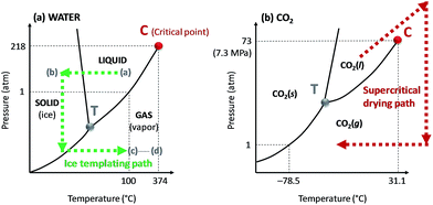 | ||
| Fig. 4 Phase diagrams of (a) water and (b) carbon dioxide (CO2). The critical and triple points are represented on the diagram by the letter C and T, respectively. The phase evolution of water and CO2 during ice sublimation and supercritical drying processes, respectively, are shown by the dashed arrows. The (a) to (d) steps on the water phase diagram corresponds to the ice templating principles detailed in Fig. 5. | ||
Here, we will distinguish between homogeneous freezing which consists in rapid freezing of a gel, from unidirectional ice templating where the orientation and (slow) growth of the ice crystals are controlled, resulting in a structured frozen dispersion (Fig. 5). The frozen solvent is removed by sublimation irrespective of how the dispersion has been frozen. Ice sublimation is commonly carried out using a freeze-dryer or a vacuum oven (Table 1), at low temperature (−55 °C) and pressure (≤0.02 mbar).
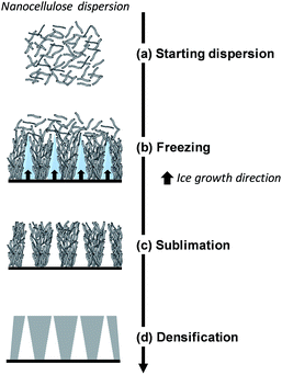 | ||
| Fig. 5 Schematic diagram of directional ice-templating of nanocellulose dispersion (adapted from Deville56). | ||
Homogeneous freezing. The freezing step usually investigated in homogeneous freezing consists in either dipping the aqueous nanocellulose-based suspension/gel in a liquid nitrogen bath or placing it in a freezer (Table 1). Rapid freezing results in an unaffected intrinsic gel structure of the wet dispersion, while slower freezing can result in segregation of the dispersed phase from the growing ice crystals. Fast freezing of aqueous CNF dispersions in liquid ethanol (−114 °C) resulted in small ice crystals and a final pore size of 1–60 nm, while slower cooling in liquid benzonitrile (−13 °C) led to larger pores after ice sublimation.32
Directional ice templating. Subjecting the freezing dispersion to a directional thermal gradient results in directional ice templating (Fig. 5).57 While homogeneous freezing leads to isotropic foams, often referred to as cellular foams with a 3D cell structure (Fig. 6a and c), unidirectional IT produces honeycomb structures, where 2D pores/cells are aligned parallel to the freezing direction (Fig. 6b and d).60 One advantage of unidirectional IT is the repeatability of the process: for similar operating conditions (cooling rate and temperature) and nanocellulose-based gel, a same porous structure can be achieved. Such a templating method, however, may require specific equipment, and a simpler technique should therefore be considered for larger scale material.58 Apart from controlling the freezing conditions, the anisotropic growth of ice crystals can be affected by an electromagnetic field,57 which may also influence the redistribution and orientation of e.g. CNC or magnetic fillers.
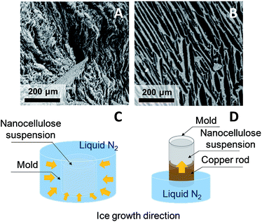 | ||
| Fig. 6 SEM images of horizontal cross-section of CNF (A) and CNC (B) foams obtained by homogeneous freezing (C) and unidirectional ice templating (D), respectively (adapted from Munier et al.60 Reproduced with the permission of ACS Publications). | ||
3. Properties of nanocellulose-based solid foams and aerogels
3.1. Density and porosity
Ultralight and highly porous nanocellulose-based solid foams and aerogels display densities ranging from 1 to 200 kg m−3,61,62 and the corresponding porosity can be higher than 99%. The bulk density of nanocellulose-based foams and aerogels depends on the initial solid concentration (Fig. 7), the possible expansion of the dispersion during the formation of the foam or structured gel, and shrinkage during solvent removal.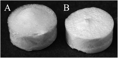 | ||
| Fig. 7 Foams obtained by homogeneous freezing and freeze-drying of (A) 0.7 and (B) 1.1 wt% carboxymethylated-pre-treated CNF dispersions (reproduced with the permission of the Royal Society of Chemistry64). | ||
The volumetric shrinkage during solvent-exchange and/or solvent removal can also be altered by the particle concentration and interactions of the nanocellulose suspension.63–65 When comparing TEMPO-CNF with Enz-CNF, Martoïa et al.32 observed that the foam shrinkage drastically increased below a critical CNF concentration, c*, below which the entangled CNF networks lost their mechanical integrity. The c* value for the highly charged TEMPO-CNF was much lower (0.2 wt%) than that of the weakly charged Enz-CNF (1 wt%). The formation of a percolative network is thus important to maintain the structure of the wet foam/gel during solvent removal and reduce the shrinkage. Crosslinking between nanocellulose may, similarly, reduce the foam/aerogel shrinkage during solvent removal.65
The density of particle-stabilized foams was found to depend on the octylamine/CNF ratio.44 Adding more octylamine resulted in a reduction of the density of the dried foams.
Solvent exchange at low temperature (−20 °C) followed by supercritical CO2 drying can preserve the porous structure of the wet foam or gel but even under these conditions, some shrinkage (between 10 and 15%) of nanocellulose-based aerogels is often observed.49
Drying of wet nanocellulose-based foams is commonly performed in an oven at 60 °C with a perforated aluminum cover over the wet foams to maintain a high humidity level.42,44 Reduced convection and high moisture content promote a uniform moisture removal and minimize the drying stress within the foam, preventing it from collapsing and shrinking. Using forced drying, Cervin et al.44 observed indeed a drastic collapse of the foam, while drying at 20 °C and 50% of relative humidity preserved the foam structure and density.
3.2. Specific surface area
High specific surface area (SSA) is desirable for foams used as e.g. insulators, electrodes, catalyst supports, and adsorbents.66A straightforward way to increase the SSA of nanocellulose foams and aerogels is to avoid pore closure, e.g. by the replacement of water by tert-butanol (TBA).66,67 Ishida et al.67 reported that the SSA of tunicate CNC foams prepared by TBA solvent exchange (130 m2 g−1) was significantly higher than that of foams prepared by freeze-drying (25 m2 g−1). Similarly, aerogels with a very high SSA (maximum of 284 m2 g−1) based on Enz-CNF and TEMPO-CNF were obtained after successive water to TBA exchanges.66 Nemoto et al.68 highlighted that the good dispersibility of nanocellulose in the solvent mixture is important to produce foams/aerogels with large SSA. By optimizing the amount of added TBA in the aqueous TEMPO-CNF dispersion, they produced TEMPO-CNF foams with SSA > 310 m2 g−1 by homogeneous freezing.68
The largest SSA value reported so far for nanocellulose-based foams/aerogels is in the range 500–600 m2 g−1 and was obtained by supercritical CO2 drying of 0.2–2 wt% TEMPO-CNF gels.63 The SSA of these aerogels did not vary with the density (ranging from 0.001 to 0.003 g cm−3), suggesting that the nanofibers did not aggregate or form dense bundles as the concentration increased.63 Sakai et al.49 confirmed that supercritical CO2 drying of TEMPO-CNF resulted in much higher SSA (=300–350 m2 g−1) than TEMPO-CNF foams produced by homogeneous freezing using water (SSA = 20 m2 g−1) or TBA (SSA = 160 m2 g−1) as solvent.
3.3. Pore size and morphology
The pore size and morphology of nanocellulose-based foams and aerogels have a strong influence on e.g. the mechanical and thermal properties. The porous architecture is strongly influenced by the processing route, but also by the particle size and shape, and interactions.Nanocellulose-based aerogels with small (<50 nm) and open pores are commonly obtained using supercritical drying.49 Ice templating of nanocellulose-based gels/dispersions templates the porous materials with open pores of diameter ≥ 50 nm, where pores are a replica of the solvent crystals.57 A rapid cooling rate can however lead to a more homogeneous fibrillar structure with smaller pores (between 1 and 60 nm) and a less pronounced sheet-like structure (Fig. 8).32 The nanocellulose gel concentration affects in particular the anisotropy ratio and size of the cells.78 A decrease in pore size and a more regular microstructure is commonly observed with an increasing particle concentration.71,81 Pores of elongated and circular cross-section were observed for CNC and CNF foams produced by unidirectional IT, respectively, which suggests that the ability of CNF to entangle and form a gel can restrict the growth of lamellar ice crystals.60 Reducing the colloidal stability of carboxylated CNF and CNC aqueous dispersions by addition of NaCl or reducing the pH resulted in a significant reduction in the degree of alignment of the nanocellulose particles in the walls of foams obtained by unidirectional IT.60
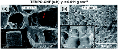 | ||
| Fig. 8 Influence of the freezing temperature on the foam morphology and pore structure obtained by homogeneous freezing (adapted from Martoïa et al.32 Reproduced with the permission of Elsevier). | ||
Use of fillers or any other polymeric matrix may also influence the final architecture of the porous solid.102 The addition of starch, for example, reduced the pore size of nanocellulose/starch composite foams by approximately 65%.78
3.4. Mechanical properties
The compressive deformation of cellular solids occurs in three main stages (Fig. 9): (i) a linear elastic behaviour caused by the cell wall bending and defined by an apparent Young's modulus, E, up to an initial apparent yield stress, σ;32 (ii) a plateau region, which marks the plastic deformation due to the collapse of the cells (or elastic buckling); and (iii) a densification regime, where the opposing cell walls approach each other and eventually touch. At a certain critical strain, the material shows considerable stiffening due to densification of the porous structure. Differences in mechanical properties between nanocellulose-based 2D honeycombs and 3D foams were assessed by Prakobna et al.73 2D honeycombs showed superior mechanical properties when tested in the longitudinal direction, as all the material was arranged along the freezing direction (see X3 direction on Fig. 9). With more isotropic cell shape, 3D foams exhibited lower longitudinal but higher transverse Young's modulus values than those of longitudinal and transverse-tested honeycombs, respectively.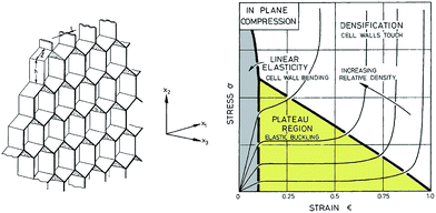 | ||
| Fig. 9 (Left) A honeycomb with hexagonal cells and plane directions. (Right) A schematic diagram for honeycomb of increasing relative density loaded in compression in the X3 direction, showing the three stages of compressive deformation (adapted from Gibson and Ashby109). | ||
The compressive behaviour of nanocellulose-based foams and aerogels is commonly described by eqn (2):74,109
 | (2) |
Honeycomb and open-cell foam models predict n = 1 and n = 2, respectively,79,109 but many materials exhibit much higher exponents.32,63 The scaling exponent of TEMPO-CNF foams (n = 2.29) obtained by direct quenching at −68 °C suggests that TEMPO-CNF foams have a microstructure and deformation mechanism similar to open-cell foams (Fig. 10).32 In contrast, the scaling exponent of Enz-CNF foams (n = 3.11) proved to be in good agreement with previous studies on cellulose or silica aerogels (3 < n < 4).110,111
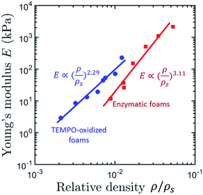 | ||
| Fig. 10 Apparent compression modulus, E, as a function of the relative density, ρ/ρs of TEMPO- and Enz-CNF foams obtained by homogeneous freezing (quenching temperature of −68 °C) (adapted from Martoïa et al.32 Reproduced with the permission of Elsevier). | ||
The work to failure or energy absorption of nanocellulose-based foams has also been assessed for packaging application. Although few studies reported this property, the work to failure is usually found to increase with increasing relative density of the material.74,109
3.5. Thermal, electrical, and acoustic properties
Foams and aerogels have low thermal conductivity, low dielectric loss and the ability to absorb sound. The acoustic properties of nanocellulose-based foams and aerogels have been assessed for CNF and CNC foams obtained by homogeneous freezing.62 At low frequencies (<1000 Hz), the sound absorption ability was poor, whereas at 4000 Hz, mechanically-treated CNF and TEMPO-CNF foams reached absorption ratios of 57 and 54%, respectively. The measured sound-absorption ratios of the 3D foams were larger than wood-based panels such as particleboard and plywood.109Neat nanocellulose foams/aerogels display a very low electrical conductivity and are suitable for devices that must transmit microwaves such as radomes, which are sandwich structures with a foam core that should display a low dielectric loss.104 Using nanocellulose in energy storage devices or thermoelectric materials, however, requires that the electrical conductivity is enhanced. Conductive materials such as polypyrrole104 or carbon nanotubes have been added to increase the electrical conductivity of the nanocellulose-based hybrids and composites.106
The thermal properties of nanocellulose-based foams and aerogels have been the focus of recent studies.49,63,80,102 The thermal conductivity of a foam or an aerogel in air can be approximated by the sum of four contributions: (i) conduction through the solid; (ii) conduction through the gas; (iii) convection within the cells; and (iv) radiation through the cell walls and across the cell voids.63,109
The conduction through the gas is usually dominating while convection is assumed to be negligible for closed foams with cell sizes below 10 mm.109 The gaseous contribution can be significantly reduced by narrowing the pore size to less than the mean free path of gas molecules in air (ca. 70–75 nm).63
The contribution of the solid phase usually scales with the bulk density of the aerogel. Kobayashi et al.63 showed that TEMPO-CNF foams (produced by supercritical CO2 drying) exhibited a decrease in thermal conductivity from 0.04 to ≈0.018 W m−1 K−1, as the density decreased from 37 to ≈17 mg cm−3, respectively. Enhancing the interfacial thermal resistance of the material, or Kapitza resistance, can contribute to reduce the thermal conductivity of a composite material.
The radiative contribution to heat transfer at room temperature is usually considered to be small. However, it is generally found to increase with increasing cell size and to decrease with increasing relative density.109 The radiative part of the thermal conduction can be reduced by including materials that strongly absorb infrared radiation such as carbonaceous materials. The addition of 10% graphene oxide in TEMPO-CNF/sepiolite/graphene oxide foams, for example, increased the mass attenuation coefficient in the mid-infrared range by 26%.80
The heat transfer properties of TEMPO-CNF foams and aerogels obtained by three different processes was recently reported and discussed.49 Aerogels of high specific surface area and small pore size (around 30 nm) exhibited increasing thermal conductivities with increasing density. Surprisingly, the thermal conductivity of CNF foams with pore sizes ranging from few micrometres to 100 micrometres range decreased with increasing density of the foams. Reasons for such a thermal behaviour are still not completely established but the authors suggested that reduction of the pore size may not be the only way to reduce the thermal conductivity of cellular solids; creating microscale spaces with distinct partitions seems to be a more efficient approach.49
Wicklein et al.80 showed that anisotropic nanocomposite foams of nanocellulose with sepiolite and graphene oxide produced by directional ice templating displayed a very low radial thermal conductivity (0.015 mW m−1 K−1) in the direction perpendicular to the ice growth.
4. Applications
Nanocellulose-based porous materials have been investigated as absorbent materials,65,68,95,112,127 templates for inorganic113,114 or carbon porous materials,115–117 gas membranes/filters,68,75 and packaging materials.79,118 This section reviews recent attempts to apply nanocellulose-based foams and aerogels as scaffolds in biomedical applications, for use in electrical devices and energy storage systems, and as thermal insulation and fire retardant materials.4.1. Scaffolds for biomedical and pharmaceutical applications
3D cell culture scaffolds usually consist of a highly interconnected porous network that favours cellular infiltration and allows proper exchange of nutrients and metabolic waste throughout the cell culture scaffold.86 To this end, bacterial nanocellulose has proven to be a promising candidate, mainly due to the durability of the bio-generated network.26 Nanocellulose-based foams and aerogels have been shown to support growth and proliferation of cells.94,97 Using 3D TEMPO-CNF aerogel scaffolds for cell cultures resulted in less than 5% of cell death after 72 h of cell growth.97 An even lower cell death was observed when low charge density TEMPO-CNF (1.56 mmol g−1 against 2.04 mmol g−1) was used to form the scaffolds. This suggests that modified nanocellulose can be considered as a biocompatible and non-toxic material.26 Similarly, CNF aerogel microspheres facilitated 3T3 NIH cell attachment, penetration, differentiation, and proliferation within 2 weeks only.86 Foams made from aldehyde-modified CNF crosslinked to collagen (2 to 7 wt%) with a good stability at different pH-values supported indeed better the growth and proliferation of cells compared with non-crosslinked foams.94 Functionalized nanocellulose-based porous materials can also serve as antibacterial materials after addition of silver104 or zinc oxide nanoparticles.77Nanocellulose foams and aerogels have also been used for controlled drug delivery. The drug release profile can be tuned by varying the porous structure of the nanocellulose foam scaffolds and by controlling the drug/cellulose interactions.119,120 For instance, adsorption of sodium salicylate (NaSA) on polyethylenimine-grafted CNF (PEI-CNF) foams enhanced the drug loading capacity by more than 20 times compared with that of neat CNF foams.92 The PEI-CNF foams also exhibited pH- and temperature responsive properties: a much faster release was achieved at neutral pH and high temperature (50 °C against 20 °C).92
4.2. Electrical devices and nanocellulose-based energy storage systems
The low density, high strength and flexibility of nanocellulose foams and aerogels are of interest in electrical devices and energy storage systems but usually require that the electrical conductivity is substantially increased. Functionalization of highly porous CNF foams with 4–7 wt% of doped polyaniline (PANI) resulted in electrical conductivity values ranging from 7 × 10⁻³ to 4 × 10⁻² S cm−1.121 The functionalization did not result in adverse effects on the structure and porosity of the entangled nanofiber network that provided a continuous percolative template for the conductive polymers. Similarly, using a dip-coating method, Zhou et al.104 synthesized CNF/polypyrrole/silver nanoparticles hybrid foams. The electrical conductivity was lower than expected (0.5 × 10⁻² S cm−1) suggesting that the silver nanoparticles were unable to form a continuous network. Compressing the functionalized foams between 30% to 70% resulted in a significant increase of the electrical conductivity from 2 × 10⁻² to 15 × 10−2 S cm−1. The pore structure can also have a significant influence on the electrical conductivity; Wang et al.88 showed that the electrical conductivity of CNF/carbon nanotube (CNT) foams produced by slow freezing (in liquid nitrogen) exhibited a higher electrical conductivity than foams obtained after rapid freezing in liquid propane (Fig. 11). The higher conductivity of the slowly frozen foams was related to the anisotropic, sheet-like pore architecture that resulted in a percolative CNF/CNT network.88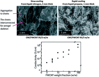 | ||
| Fig. 11 Influence of cooling temperature on the electrical conductivity of CNF/FWCNT (few walled carbon nanotubes) foams produced by homogeneous freezing. The conductivity of foams frozen either in liquid nitrogen or in liquid propane are represented by the full black and hollow dots, respectively (adapted from Wang et al.88 Reproduced with the permission of Wiley Online Library). | ||
The Layer by Layer (LbL) assembly technique has also been used to produce conductive nanocellulose-based foams and aerogels. LbL assembly of functional polymers and nanoparticles was used to assemble a succession of thin films (from 5 to 10 bilayers of cationic and anionic polymers) on negatively charged carboxymethylated CNF aerogels.106 LbL coatings of poly(3,4-ethylenedioxythiophene):poly(styrene sulfonate) (PEDOT:PSS) and single-wall carbon nanotubes (SWCNT) to the CNF aerogels resulted in an electrical conductivity of 1.4 × 10⁻⁵ S cm−1 (for 10 bilayers) and 1.2 × 10⁻³ S cm−1 (for 5 bilayers), respectively. The SWCNT/CNF aerogels were also used as electrodes in an aqueous supercapacitor, resulting in a device with a capacitance estimated to 419 F g−1; a much higher value than previously reported for SWCNT coated paper substrates (200 F g−1)122 or SWCNT LbL freestanding films (159 F g−1).123
The LbL approach has also been used to assemble a 3D energy-storage device inside of a CNF aerogel.107 Anionically charged CNF aerogels were produced by homogeneous freezing and crosslinked using butanetetracarboxylic acid (BTCA) and sodium hypophosphite (NaPO2H2) to form wet-resilient aerogels.
LbL was used to deposit the first electrode on the CNF aerogels using a total of five bilayers of [COOH-functionalized CNT/polyethylenimine (PEI)] (see Fig. 12, left picture).106 The separator was made of a 30-bilayer film of PEI/polyacrylic acid (PAA) (Fig. 12, middle picture).
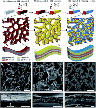 | ||
| Fig. 12 (a) Energy-storage device assembly in a CNF aerogel by LbL technique and (b and c) SEM cross sections of the respective first PEI/CNT electrode (left), the PEI/CNT electrode with separator (middle), and the full device (right). Scale bars (b) 50 μm and (c) 2 μm (reproduced with the permission of Macmillan Publishers Limited107). | ||
The second electrode was then deposited, using five bilayers of PEI and COOH-functionalized SWCNT (Fig. 12, right picture).
The device displayed the typical square-shaped voltammograms for supercapacitors resulting from double-layer charging of a carbon surface, and a capacitance of 25 F g−1 over 400 cycles, comparable to traditional carbon-based supercapacitors.107 LbL coated CNF aerogels have also been used as scaffolds for batteries, using PEI/CNT layers as anode, the PEI/PAA layer as separator and a copper hexacyanoferrate as cathode.
Yang et al.124 incorporated capacitive nanoparticles, either polypyrrole nanofibers, or polypyrrole-coated carbon nanotubes or spherical manganese dioxide nanoparticles to dispersions of aldehyde- and hydrazide modified CNC, which formed covalent hydrazone cross-links immediately upon contact.124 Rapid freezing followed by freeze drying of these hybrid networks resulted in aerogels with a high porosity (∼99%) that displayed excellent capacitance retention (between 40 and 45%) at high charge–discharge rates (up to 1000 mV s−1) as well as good cycle stability. Only minor changes in capacitive performance were noticed during in situ compression, highlighting, once again, the excellent mechanical properties provided by the nanocellulose scaffold.
4.3. Thermally insulating and fire retardant materials
Cellulose has a low solid thermal conductivity that makes cellulose-based materials useful for thermal insulation. Traditional cellulose-based insulation materials display thermal conductivities in the range of 40–50 mW m−1 K−1, which is somewhat higher than modern polymer or mineral wool based insulating materials.93,125Recent works have shown that nanocellulose foams and aerogels can display thermal conductivity below 25 mW m−1 K−1 (=air conductivity), which classifies them as superinsulating materials.49,63,80,126,127
Attempts have been made to reduce the thermal conductivity by combining nanocelluloses with other nanosized or nanoporous particles.80,102,126,127
Wicklein et al.80 combined nanocelluloses with graphene oxide and sepiolite and produced anisotropic composite foams by ice templating. The foams displayed a very low thermal conductivity in the direction transverse to the tubular macropores. The reduction of the thermal conductivity from 18 to 15 mW m−1 K−1 compared to neat CNF foams was related to an enhanced interfacial thermal resistance in the pore walls of the composite foams.
It was suggested that the nanocellulose-based foams could replace standard commercial EPS foams (λ = 35 mW m−1 K−1) with a 50% reduction in thickness needed to reach passive house standard (Fig. 13a).
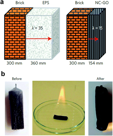 | ||
| Fig. 13 Thermal insulation and fire retardancy of nanocellulose-based composite foam containing sepiolite (SEP), graphene oxide (GO) and boric acid: (a) comparison of the insulation thickness of expanded polystyrene (EPS) and composite foam (CNF–SEP–GO) needed to reach passive house standard (b) burning test of the nanocomposite foams soaked in ethanol resulted in a carbonized residue (reproduced with the permission of Macmillan Publisher Limited80). | ||
The nanocomposite foams also showed excellent fire retardancy (Fig. 13b). The addition of inorganic fillers such as clays or graphene is a well-known approach to enhance the fire retardant properties of organic and inorganic composites.128 The Limiting Oxygen Index (LOI) was as high as 34, which is significantly better than commercial flame-retardant containing polymer-based foams, which display LOI in the range 22–25.
Conclusions and outlook
Nanocellulose possesses a combination of properties suitable for the production of ultralight, strong and flexible foams and aerogels for a rapidly growing range of applications. Several processing routes have been developed that enable production of nanocellulose-based foams and aerogels with a tunable porosity and pore architecture. Studies on the properties and structure of the wet foams are sparse and a fundamental understanding of the stability of the foams is still lacking. Studies on how the stability and dynamics of the air–liquid interface is influenced by nanocellulose could provide important insight into how the wet foams stability can be enhanced.Challenges related to uncontrolled structural changes during solvent removal are currently limiting the scale up and there is a need for novel solvent-removal processes and a better understanding on how to minimize the structural changes during drying. Simplified solvent exchange and supercritical drying processes could be of potential interest. Time-resolved tomographic studies during drying coupled with information on the drying front movement and local drying stresses could also be used to provide a deeper understanding and perhaps also guidelines on how to minimize the stresses during drying of nanocellulose-based foams and aerogels.
The compressive behaviour of nanocellulose-based foams is relatively well studied and is well explained by cellular solids models. Studies on the electrical and thermal properties, on the other hand, are rare and the structure–property relationships are not well established.
Promising advanced materials have been achieved by combining nanocellulose with other nanosized components. Selection of the foam/aerogel wall composition is of pivotal importance for imparting novel functionalities to the material such as electrical conductivity or fire retardancy.
We expect that the research on nanocellulose-based foams and aerogels will continue to grow and look forward to the development of novel process routes and lightweight materials with outstanding properties for target applications.
Acknowledgements
The authors acknowledge the Stiftelsen för strategisk forskning (RMA11-0065), Energimyndigheten (P40121-1), Svenska forskningsrådet Formas (2015-1032), and the Wallenberg Wood Science Centre (WWSC) for financial support.References
- Y. Habibi, L. A. Lucia and O. J. Rojas, Chem. Rev., 2010, 110, 3479–3500 CrossRef CAS PubMed.
- Y. Habibi, Chem. Soc. Rev., 2014, 43, 1519–1542 RSC.
- J. P. F. Lagerwall, C. Schutz, M. Salajkova, J. Noh, J. Hyun Park, G. Scalia and L. Bergstrom, NPG Asia Mater., 2014, 6, e80 CrossRef CAS.
- N. Lavoine, I. Desloges, A. Dufresne and J. Bras, Carbohydr. Polym., 2012, 90, 735–764 CrossRef CAS PubMed.
- T. Abitbol, A. Rivkin, Y. Cao, Y. Nevo, E. Abraham, T. Ben-Shalom, S. Lapidot and O. Shoseyov, Curr. Opin. Biotechnol., 2016, 39, 76–88 CrossRef CAS PubMed.
- B. G. Rånby and E. Ribi, Experientia, 1950, 6, 12–14 CrossRef.
- S. Beck-Candanedo, M. Roman and D. G. Gray, Biomacromolecules, 2005, 6, 1048–1054 CrossRef CAS PubMed.
- H. Yu, Z. Qin, B. Liang, N. Liu, Z. Zhou and L. Chen, J. Mater. Chem. A, 2013, 1, 3938–3944 CAS.
- E. Kontturi, A. Meriluoto, P. A. Penttilä, N. Baccile, J.-M. Malho, A. Potthast, T. Rosenau, J. Ruokolainen, R. Serimaa, J. Laine and H. Sixta, Angew. Chem., Int. Ed., 2016, 55, 14455–14458 CrossRef CAS PubMed.
- S. Camarero Espinosa, T. Kuhnt, E. J. Foster and C. Weder, Biomacromolecules, 2013, 14, 1223–1230 CrossRef CAS PubMed.
- H. Sadeghifar, I. Filpponen, S. P. Clarke, D. F. Brougham and D. S. Argyropoulos, J. Mater. Sci., 2011, 46, 7344–7355 CrossRef CAS.
- Y. Liu, H. Wang, G. Yu, Q. Yu, B. Li and X. Mu, Carbohydr. Polym., 2014, 110, 415–422 CrossRef CAS PubMed.
- A. Dufresne, Nanocellulose: From Nature to High Performance Tailored Materials, De Gruyter, France, 2012 Search PubMed.
- I. Siró, D. Plackett, M. Hedenqvist, M. Ankerfors and T. Lindström, J. Appl. Polym. Sci., 2011, 119, 2652–2660 CrossRef.
- A. Isogai, T. Saito and H. Fukuzumi, Nanoscale, 2011, 3, 71–85 RSC.
- A. Pei, N. Butchosa, L. A. Berglund and Q. Zhou, Soft Matter, 2013, 9, 2047–2055 RSC.
- M. Henriksson, G. Henriksson, L. A. Berglund and T. Lindström, Eur. Polym. J., 2007, 43, 3434–3441 CrossRef CAS.
- O. Nechyporchuk, M. N. Belgacem and J. Bras, Ind. Crops Prod., 2016, 17, 2311–2320 CAS.
- A. Dufresne, Can. J. Chem., 2008, 86, 484–494 CrossRef CAS.
- D. Klemm, F. Kramer, S. Moritz, T. Lindström, M. Ankerfors, D. Gray and A. Dorris, Angew. Chem., Int. Ed., 2011, 50, 5438–5466 CrossRef CAS PubMed.
- I. Siró and D. Plackett, Cellulose, 2010, 17, 459–494 CrossRef.
- G. Siqueira, J. Bras and A. Dufresne, Polymers, 2010, 2, 728–765 CrossRef CAS.
- F. Li, E. Mascheroni and L. Piergiovanni, Packag. Technol. Sci., 2015, 28, 475–508 CrossRef CAS.
- A. Serpa, J. Velásquez-Cock, P. Gañán, C. Castro, L. Vélez and R. Zuluaga, Food Hydrocolloids, 2016, 57, 178–186 CrossRef.
- F. W. Brodin, Ø. W. Gregersen and K. Syverud, Nord. Pulp Pap. Res. J., 2014, 29, 156–166 CAS.
- M. Jorfi and E. J. Foster, J. Appl. Polym. Sci., 2015, 132, 41719–41738 CrossRef.
- P. Gatenholm and D. Klemm, MRS Bull., 2010, 35, 208–213 CrossRef CAS.
- F. Hoeng, A. Denneulin and J. Bras, Nanoscale, 2016, 8, 13131–13154 RSC.
- O. Nechyporchuk, M. N. Belgacem and F. Pignon, Biomacromolecules, 2016, 73, 2311–2320 CrossRef PubMed.
- K. Missoum, M. N. Belgacem and J. Bras, Materials, 2013, 6, 1745–1766 CrossRef CAS.
- H. Sehaqui, M. Salajková, Q. Zhou and L. A. Berglund, Soft Matter, 2010, 6, 1824–1832 RSC.
- F. Martoïa, T. Cochereau, P. J. J. Dumont, L. Orgéas, M. Terrien and M. N. Belgacem, Mater. Des., 2016, 104, 376–391 CrossRef.
- G. D. Miles and J. Ross, J. Phys. Chem., 1944, 48, 280–290 CrossRef CAS.
- J. J. Bikerman, Trans. Faraday Soc., 1938, 34, 634–638 RSC.
- O. Faruk, A. K. Bledzki and L. M. Matuana, Macromol. Mater. Eng., 2007, 292, 113–127 CrossRef CAS.
- A. Saint-Jalmes, Soft Matter, 2006, 2, 836–849 RSC.
- S. Lam, K. P. Velikov and O. D. Velev, Curr. Opin. Colloid Interface Sci., 2014, 19, 490–500 CrossRef CAS.
- T. N. Hunter, R. J. Pugh, G. V. Franks and G. J. Jameson, Adv. Colloid Interface Sci., 2008, 137, 57–81 CrossRef CAS PubMed.
- G. Kaptay, Colloids Surf., A, 2003, 230, 67–80 CrossRef CAS.
- G. Kaptay, Colloids Surf., A, 2006, 282, 387–401 CrossRef.
- A.-L. Fameau and A. Salonen, C. R. Phys., 2014, 15, 748–760 CrossRef CAS.
- K. S. Gordeyeva, A. B. Fall, S. Hall, B. Wicklein and L. Bergström, J. Colloid Interface Sci., 2016, 472, 44–51 CrossRef CAS PubMed.
- B. P. Binks, Curr. Opin. Colloid Interface Sci., 2002, 7, 21–41 CrossRef CAS.
- N. T. Cervin, L. Andersson, J. B. S. Ng, P. Olin, L. Bergström and L. Wågberg, Biomacromolecules, 2013, 14, 503–511 CrossRef CAS PubMed.
- N. T. Cervin, E. Johansson, J. W. Benjamins and L. Wågberg, Biomacromolecules, 2015, 16, 822–831 CrossRef CAS PubMed.
- Z. Hu, R. Xu, E. D. Cranston and R. H. Pelton, Biomacromolecules, 2016, 17, 4095–4099 CrossRef CAS PubMed.
- K.-Y. Lee, J. J. Blaker, R. Murakami, J. Y. Y. Heng and A. Bismarck, Langmuir, 2014, 30, 452–460 CrossRef CAS PubMed.
- S. Tasset, B. Cathala, H. Bizot and I. Capron, RSC Adv., 2014, 4, 893–898 RSC.
- K. Sakai, Y. Kobayashi, T. Saito and A. Isogai, Sci. Rep., 2016, 6, 20434–20441 CrossRef PubMed.
- G. W. Scherer, J. Non-Cryst. Solids, 1986, 87, 199–225 CrossRef CAS.
- A. C. Pierre and G. M. Pajonk, Chem. Rev., 2002, 102, 4243–4266 CrossRef CAS PubMed.
- G. Della Porta, P. Del Gaudio, F. De Cicco, R. P. Aquino and E. Reverchon, Ind. Eng. Chem. Res., 2013, 52, 12003–12009 CrossRef CAS.
- L. Heath and W. Thielemans, Green Chem., 2010, 12, 1448–1453 RSC.
- F. Liebner, E. Haimer, M. Wendland, M.-A. A. Neouze, K. Schlufter, P. Miethe, T. Heinze, A. Potthast and T. Rosenau, Macromol. Biosci., 2010, 10, 349–352 CrossRef CAS PubMed.
- L. M. Sanz-Moral, M. Rueda, R. Mato and Á. Martín, J. Supercrit. Fluids, 2014, 92, 24–30 CrossRef CAS.
- S. Deville, Materials, 2010, 3, 1913–1927 CrossRef CAS.
- S. Deville, J. Mater. Res., 2013, 28, 2202–2219 CrossRef CAS.
- W. L. Li, K. Lu and J. Y. Walz, Int. Mater. Rev., 2013, 57, 37–60 CrossRef.
- M. V. G. Zimmermann, C. Borsoi, A. Lavoratti, M. Zanini, A. J. Zattera and R. M. C. Santana, J. Reinf. Plast. Compos., 2016, 35, 682–697 CrossRef CAS.
- P. Munier, K. Gordeyeva, L. Bergström and A. B. Fall, Biomacromolecules, 2016, 17, 1875–1881 CrossRef CAS PubMed.
- N. Tchang Cervin, E. Johansson, P. A. Larsson and L. Wagberg, ACS Appl. Mater. Interfaces, 2016, 8, 11682–11689 Search PubMed.
- W. Chen, Q. Li, Y. Wang, X. Yi, J. Zeng, H. Yu, Y. Liu and J. Li, ChemSusChem, 2014, 7, 154–161 CrossRef CAS PubMed.
- Y. Kobayashi, T. Saito and A. Isogai, Angew. Chem., Int. Ed. Engl., 2014, 53, 10394–10397 CrossRef CAS PubMed.
- C. Aulin, J. Netrval, L. Wågberg and T. Lindström, Soft Matter, 2010, 6, 3298–3305 RSC.
- X. Yang and E. D. Cranston, Chem. Mater., 2014, 26, 6016–6025 CrossRef CAS.
- H. Sehaqui, Q. Zhou and L. A. Berglund, Compos. Sci. Technol., 2011, 71, 1593–1599 CrossRef CAS.
- O. Ishida, D.-Y. Kim, S. Kuga, Y. Nishiyama and R. M. Brown, Cellulose, 2004, 11, 475–480 CrossRef CAS.
- J. Nemoto, T. Saito and A. Isogai, ACS Appl. Mater. Interfaces, 2015, 7, 19809–19815 CAS.
- N. Pircher, S. Veigel, N. Aigner, J. M. M. Nedelec, T. Rosenau and F. Liebner, Carbohydr. Polym., 2014, 111, 505–513 CrossRef CAS PubMed.
- M. Granström, M. K. née Pääkkö, H. Jin, E. Kolehmainen, I. Kilpeläinen and O. Ikkala, Polym. Chem., 2011, 2, 1789–1796 RSC.
- J. Lee and Y. Deng, Soft Matter, 2011, 7, 6034–6040 RSC.
- A. J. Svagan, M. A. S. A. Samir and L. A. Berglund, Adv. Mater., 2008, 20, 1263–1269 CrossRef CAS.
- K. Prakobna, F. Berthold, L. Medina and L. A. Berglund, Composites, Part A, 2016, 88, 116–122 CrossRef CAS.
- Z. M. Ali and L. J. Gibson, Soft Matter, 2013, 9, 1580–1588 RSC.
- H. Sehaqui, M. E. Gálvez, V. Becatinni, Y. Cheng Ng, A. Steinfeld, T. Zimmermann and P. Tingaut, Environ. Sci. Technol., 2015, 49, 3167–3174 CrossRef CAS PubMed.
- R. Dash, Y. Li and A. J. Ragauskas, Carbohydr. Polym., 2012, 88, 789–792 CrossRef CAS.
- P. Wang, J. Zhao, R. Xuan, Y. Wang, C. Zou, Z. Zhang, Y. Wan and Y. Xu, Dalton Trans., 2014, 43, 6762–6768 RSC.
- A. J. Svagan, P. Jensen, S. V. Dvinskikh, I. Furó and L. A. Berglund, J. Mater. Chem., 2010, 20, 6646–6654 RSC.
- A. E. Donius, A. Liu, L. A. Berglund and U. G. K. K. Wegst, J. Mech. Behav. Biomed. Mater., 2014, 37, 88–99 CrossRef CAS PubMed.
- B. Wicklein, A. Kocjan, G. Salazar-Alvarez, F. Carosio, G. Camino, M. Antonietti and L. Bergström, Nat. Nanotechnol., 2015, 10, 277–283 CrossRef CAS PubMed.
- Z.-Z. Pan, H. Nishihara, S. Iwamura, T. Sekiguchi, A. Sato, A. Isogai, F. Kang, T. Kyotani and Q.-H. Yang, ACS Nano, 2016, 10, 10689–10697 CrossRef CAS PubMed.
- H. Jin, M. Kettunen, A. Laiho, H. Pynnönen, J. Paltakari, A. Marmur, O. Ikkala and R. H. A. Ras, Langmuir, 2011, 27, 1930–1934 CrossRef CAS PubMed.
- J. T. Korhonen, M. Kettunen, R. H. A. Ras and O. Ikkala, ACS Appl. Mater. Interfaces, 2011, 3, 1813–1816 CAS.
- M. Kettunen, R. J. Silvennoinen, N. Houbenov, A. Nykänen, J. Ruokolainen, J. Sainio, V. Pore, M. Kemell, M. Ankerfors, T. Lindström, M. Ritala, R. H. A. Ras and O. Ikkala, Adv. Funct. Mater., 2011, 21, 510–517 CrossRef CAS.
- W. Zhang, Y. Zhang, C. Lu and Y. Deng, J. Mater. Chem., 2012, 22, 11642–11650 RSC.
- H. Cai, S. Sharma, W. Liu, W. Mu, W. Liu, X. Zhang and Y. Deng, Biomacromolecules, 2014, 15, 2540–2547 CrossRef CAS PubMed.
- J. C. Arboleda, M. Hughes, L. A. Lucia, J. Laine, K. Ekman and O. J. Rojas, Cellulose, 2013, 20, 2417–2426 CrossRef CAS.
- M. Wang, I. V. Anoshkin, A. G. Nasibulin, J. T. Korhonen, J. Seitsonen, J. Pere, E. I. Kauppinen, R. H. A. Ras and O. Ikkala, Adv. Mater., 2013, 25, 2428–2432 CrossRef CAS PubMed.
- M. Fumagalli, F. Sanchez, S. M. Boisseau and L. Heux, Soft Matter, 2013, 9, 11309–11317 RSC.
- M. Fumagalli, F. Sanchez, S. Molina-Boisseau and L. Heux, Cellulose, 2015, 22, 1451–1457 CrossRef CAS.
- Z. Zhang, G. Sèbe, D. Rentsch, T. Zimmermann and P. Tingaut, Chem. Mater., 2014, 26, 2659–2668 CrossRef CAS.
- J. Zhao, C. Lu, X. He, X. Zhang, W. Zhang and X. Zhang, ACS Appl. Mater. Interfaces, 2015, 7, 2607–2615 CAS.
- J. Fu, S. Wang, C. He, Z. Lu, J. Huang and Z. Chen, Carbohydr. Polym., 2016, 147, 89–96 CrossRef CAS PubMed.
- T. Lu, Q. Li, W. Chen and H. Yu, Compos. Sci. Technol., 2014, 94, 132–138 CrossRef CAS.
- F. Jiang and Y.-L. Hsieh, J. Mater. Chem. A, 2014, 2, 350–359 CAS.
- T. Saito, T. Uematsu, S. Kimura, T. Enomae and A. Isogai, Soft Matter, 2011, 7, 8804–8809 RSC.
- J. Liu, F. Cheng, H. Grénman, S. Spoljaric, J. Seppälä, J. E. Eriksson, S. Willför and C. Xu, Carbohydr. Polym., 2016, 148, 259–271 CrossRef CAS PubMed.
- T. C. F. Silva, Y. Habibi, J. L. Colodette, T. Elder and L. A. Lucia, Cellulose, 2012, 19, 1945–1956 CrossRef CAS.
- H. Dong, J. F. Snyder, D. T. Tran and J. L. Leadore, Carbohydr. Polym., 2013, 95, 760–767 CrossRef CAS PubMed.
- J. Lin, L. Yu, F. Tian, N. Zhao, X. Li, F. Bian and J. Wang, Carbohydr. Polym., 2014, 109, 35–43 CrossRef CAS PubMed.
- F. Jiang and Y.-L. Hsieh, J. Mater. Chem. A, 2014, 2, 6337–6342 CAS.
- D. Bendahou, A. Bendahou, B. Seantier, Y. Grohens and H. Kaddami, Ind. Crops Prod., 2015, 65, 374–382 CrossRef CAS.
- Q. Zheng, Z. Cai, Z. Ma and S. Gong, ACS Appl. Mater. Interfaces, 2015, 7, 3263–3271 CAS.
- S. Zhou, M. Wang, X. Chen and F. Xu, ACS Sustainable Chem. Eng., 2015, 3, 3346–3354 CrossRef CAS.
- N. T. Cervin, C. Aulin, P. T. Larsson and L. Wågberg, Cellulose, 2012, 19, 401–410 CrossRef CAS.
- M. Hamedi, E. Karabulut, A. Marais, A. Herland and G. Nyström, Angew. Chem., Int. Ed., 2013, 52, 12038–12042 CrossRef CAS PubMed.
- G. Nyström, A. Marais, E. Karabulut, L. Wågberg, Y. Cui and M. M. Hamedi, Nat. Commun., 2015, 6, 7259 CrossRef PubMed.
- H. Sai, R. Fu, L. Xing, J. Xiang, Z. Li, F. Li and T. Zhang, ACS Appl. Mater. Interfaces, 2015, 7, 7373–7381 CAS.
- L. J. Gibson and M. F. Ashby, Cellular solids: structure and properties, Cambridge University Press, 1999 Search PubMed.
- T. Woignier, J. Reynes, A. Hafidi Alaoui, I. Beurroies and J. Phalippou, J. Non-Cryst. Solids, 1998, 241, 45–52 CrossRef CAS.
- R. Sescousse, R. Gavillon and T. Budtova, Carbohydr. Polym., 2011, 83, 1766–1774 CrossRef CAS.
- H. Liu, B. Geng, Y. Chen and H. Wang, ACS Sustainable Chem. Eng., 2016, 5, 49–66 CrossRef.
- J. T. Korhonen, P. Hiekkataipale, J. Malm, M. Karppinen, O. Ikkala and R. H. A. Ras, ACS Nano, 2011, 5, 1967–1974 CrossRef CAS PubMed.
- T. Hees, F. Zhong, T. Rudolph, A. Walther and R. Mülhaupt, Adv. Funct. Mater., 2017, 27, 1605586–1605594 CrossRef.
- B. Wang, X. Li, B. Luo, J. Yang, X. Wang, Q. Song, S. Chen and L. Zhi, Small, 2013, 9, 2399–2404 CrossRef CAS PubMed.
- Y. Meng, T. M. Young, P. Liu, C. I. Contescu, B. Huang and S. Wang, Cellulose, 2015, 22, 435–447 CrossRef CAS.
- J. Štefelová, V. Slovák, G. Siqueira, R. T. Olsson, P. Tingaut, T. Zimmermann and H. Sehaqui, ACS Sustainable Chem. Eng., 2017, 5, 2679–2692 CrossRef.
- M. Ago, A. Ferrer Carrera and O. J. Rojas, ACS Sustainable Chem. Eng., 2016, 4, 5546–5552 CrossRef CAS.
- H. Valo, S. Arola, P. Laaksonen, M. Torkkeli, L. Peltonen, M. B. Linder, R. Serimaa, S. Kuga, J. Hirvonen and T. Laaksonen, Eur. J. Pharm. Sci., 2013, 50, 69–77 CrossRef CAS PubMed.
- A. J. Svagan, J. W. Benjamins, Z. Al-Ansari, D. B. Shalom, A. Müllertz, L. Wågberg and K. Löbmann, J. Controlled Release, 2016, 244, 74–82 CrossRef CAS PubMed.
- M. Pääkkö, J. Vapaavuori, R. Silvennoinen, H. Kosonen, M. Ankerfors, T. Lindström, L. Berglund and O. Ikkala, Soft Matter, 2008, 4, 2492–2499 RSC.
- L. Hu, J. W. Choi, Y. Yang, S. Jeong, F. La Mantia, L.-F. Cui and Y. Cui, Proc. Natl. Acad. Sci. U. S. A., 2009, 106, 21490–21494 CrossRef CAS PubMed.
- S. W. Lee, B.-S. Kim, S. Chen, Y. Shao-Horn and P. T. Hammond, J. Am. Chem. Soc., 2009, 131, 671–679 CrossRef CAS PubMed.
- X. Yang, K. Shi, I. Zhitomirsky and E. D. Cranston, Adv. Mater., 2015, 27, 6104–6109 CrossRef CAS PubMed.
- J. Kuhn, H. P. Ebert, M. C. Arduini-Schuster, D. Büttner and J. Fricke, Int. J. Heat Mass Transfer, 1992, 35, 1795–1801 CrossRef CAS.
- B. Seantier, D. Bendahou, A. Bendahou, Y. Grohens and H. Kaddami, Carbohydr. Polym., 2016, 138, 335–348 CrossRef CAS PubMed.
- C. Jiménez-Saelices, B. Seantier, B. Cathala and Y. Grohens, Carbohydr. Polym., 2017, 157, 105–113 CrossRef PubMed.
- T. Kashiwagi, F. Du, J. F. Douglas, K. I. Winey, R. H. Harris and J. R. Shields, Nat. Mater., 2005, 4, 928–933 CrossRef CAS PubMed.
| This journal is © The Royal Society of Chemistry 2017 |


