A molecular dynamics investigation on the cross-linking and physical properties of epoxy-based materials†
Lik-ho Tama and
Denvid Lau*ab
aDepartment of Architecture and Civil Engineering, City University of Hong Kong, Hong Kong, China
bDepartment of Civil and Environmental Engineering, Massachusetts Institute of Technology, Cambridge, MA 02139, USA. E-mail: denvid@mit.edu
First published on 21st July 2014
Abstract
Epoxy-based materials are extensively used in industry due to their excellent mechanical and thermal stability. As the epoxy products are getting smaller and smaller nowadays, there are difficulties arising from the material processing and measurement, which need to be carefully considered in the design stage. SU-8 photoresist, which is commonly used in micro-electro-mechanical systems (MEMS), is chosen as a representative of epoxy-based materials in this study. Here, we propose an effective dynamic cross-linking algorithm, which can be used to construct the SU-8 epoxy network with cross-linking degree higher than 80%. Using an equilibration process incorporating successive pressure controls, the density of the cross-linked structure can be accurately obtained. By performing the dynamic deformations in the molecular dynamics simulations, elastic properties of the equilibrated SU-8 photoresist can be determined, which are in good agreement with the experimental measurements. The good predictions of the physical properties demonstrate a strong mechanical stability of the SU-8 structure at the nano-scale. The dynamic cross-linking algorithm described in the present study can be applied in other polymeric material investigations involving the cross-linked network model through homopolymerization.
Introduction
Epoxy-based materials possess a three-dimensional covalent network formed by a cross-linking process among epoxy monomers, which is normally initiated by heat, chemical reaction or irradiation. The highly cross-linked epoxy network exhibits enhanced physical properties, such as strong structural stability including high thermal and chemical resistance. In practice, these materials are frequently used in various engineering applications across a large range of length scales, including micro-electro-mechanical systems (MEMS), civil infrastructures and aerospace industry.1–3 Particularly, SU-8 has become a favorable epoxy-based photoresist for the fabrication of high-aspect ratio and three-dimensional MEMS.4 Compared with other commonly used photoresists such as poly(methyl methacrylate) (PMMA),5 SU-8 has a higher Young's modulus after the polymerization process,6–9 which is important for achieving a better mechanical stability of the final products. However, the focus of these earlier studies is mainly on SU-8 measurements at the micro-scale. As the dimensions of SU-8 applications shrink to sub-micro or even nano-scale, investigations are required to probe the SU-8 mechanical properties at these tiny length scales. However, the difficulties in material processing for conventional tensile tests become major limitations to obtain the nano-mechanical properties of the epoxy-based materials, such as SU-8 photoresist.Molecular dynamics (MD) simulations have been demonstrated as a powerful tool to study the molecular structure and mechanical properties of cross-linked networks.10–22 The early MD studies in the polymer investigations involving the construction of atomistic polymeric systems have been reported since 1990s.10,11 Several static cross-linking approaches have been developed for the formation of cross-linked networks.11,12 In their proposed approaches, the reactive atoms whose distance are closer than a defined reaction radius are firstly identified, and then the identified reactive atoms are cross-linked by forming new bonds simultaneously (in a single step). As the cross-linking process is performed at only one step, some potential reactive atoms are not cross-linked, which results in a low cross-linking degree. Alternatively, the identification of reactive atoms and the creation of new bonds can be carried out in a successive manner,13,18 in which the reaction radius can increase steadily during the cross-linking process, leading to a higher cross-linking degree compared to the previous static methods. However, the generated cross-linked structure using such approach may not be fully equilibrated after every polymerization reaction. In other words, this approach limits the system to relax adequately and it is expected that a high geometric instability can be resulted due to the newly created bonds. By incorporating energy minimization and molecular equilibration after each cross-linking reaction, a dynamic cross-linking approach14 has been proposed to reduce the geometric instability arose during the cross-linked network formation. But as this approach only performs one bond formation between the closest reactive atoms pair per iteration, a heavy computational demand in large scale systems is expected. Besides, the reported Young's modulus of the epoxy network using a dynamic cross-linking approach with Dreiding forcefield is a magnitude larger than the experimental measurement.23 By combining the successive cross-linking concept13 and the multistep relaxation procedures,14 the cross-linking reaction can be simulated in a step wise manner.16 During the cross-linking network formation, the bond energy of the newly created bonds can be determined based on the value of bond length (distance between the cross-linked atoms), which changes constantly during the relaxation process. The calculation of bond length can be performed in every equilibration step to determine the force constant, which is time consuming and computational demanding. Whereas these MD studies have made significant progress in the molecular modeling and properties measurement of epoxy-based materials, several key obstacles are still present including the low cross-linking degree11,12 and less accuracy in the properties predictions.14,16 Our cross-linking algorithm developed in this paper has a similarity in the spirit to the dynamic concept,13,14,16 but with a significant improvement in terms of the time efficiency and the accuracy, as well as a high extensibility to other cross-linked networks. Specifically, a combined equilibration process is adopted after each cross-linking reaction, which relaxes the newly created bonds to an equilibrium state with less simulation time frames. In addition, the force constant in the bond stretching interaction does not change during the equilibration process, which provides a flexible control over the bond stretching interaction in a simpler way.
The objective of this paper is to develop a cross-linking algorithm which is capable of constructing a highly cross-linked network and predicting the physical properties in close agreement with experimental measurements. In this paper, the atomistic modeling of SU-8 epoxy network is first introduced from the perspective of the chosen forcefields, followed by the main focus of this paper, which is the cross-linking algorithm. Our algorithm is used to construct a highly cross-linked network of the SU-8 epoxy photoresist, which is relaxed under successive external pressure controls to reach an equilibrium state. Eventually, various elastic properties of the epoxy network are then determined by MD simulations. This study represents an initial step for developing a more sophisticated and realistic epoxy model at nano-scale, in which some nano-scale features like defect and inclusion can be incorporated.
Simulation details
Forcefields
The detailed atomistic interactions in the SU-8 molecular structure are described by a forcefield, which determines the potential energy of all the atoms based on their positions and internal coordinates, including bond lengths, bond angles, torsion angles and improper out-of-plane angles. Two constituents are involved in a forcefield, including the functional forms in the energy expression and their parameters. In general, the energy expression comprises a set of bonded and non-bonded interactions, as well as cross-coupling terms between the internal coordinates in some forcefields. As the accuracy of MD simulations highly depends on the selected forcefield,14,15 the investigations of SU-8 photoresist are carried out using three different forcefields independently in order to obtain a comprehensive picture, which include consistent valence forcefield (CVFF),24,25 Dreiding forcefield26 and polymer consistent forcefield (PCFF).27 These three forcefields are chosen as they are well reported to be applicable to the simulations of epoxy-based materials.12,16,17,19,20,22 The detailed introduction of the three forcefields is described in the ESI.†Partial charges assignment of atoms varies among these three forcefields. In the simulations using CVFF and PCFF, partial charges are estimated by using a bond increment method.27,28 The bond increment δij is described as the partial charge contributed from atom j to atom i. This method assigns δij with equal magnitude and opposite sign to each pair of bonded atoms i and j. For atom i, the charge is calculated by the summation of δij as given in eqn (1).
 | (1) |
Atomistic modeling of SU-8 photoresist is performed in Materials Studio software from Accelrys.30 After constructing the cross-linked SU-8 epoxy network with a clear definition of the model structure and the interaction between atoms, MD simulations are performed in the open source code LAMMPS.31 The msi2lmp tool in LAMMPS is used to generate the input data containing the structural information and the forcefield parameters. Periodic boundary conditions are applied to all three directions for studying the SU-8 physical properties.
Cross-linking process
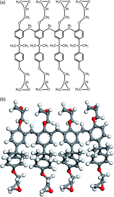
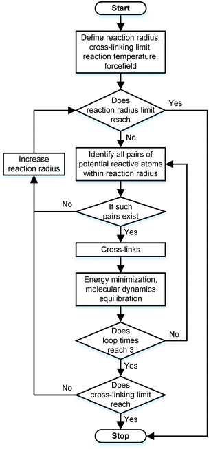
During the experimental polymerization process, the SU-8 cross-linking process is stimulated by the UV radiation, which does not require any external liquid curing agents. The cross-linked SU-8 photoresist is polymerized of SU-8 monomers with a three-dimensional periodic boundary condition. The SU-8 monomer comprises four components of diglycidyl ether of bisphenol A (DGEBA) and the chemical structure of which is shown in Fig. 1a. With eight epoxide groups in each monomer, SU-8 possesses the highest epoxide functionality among the commercially available photoresists. The high epoxide functionality enables SU-8 photoresist to grow into a highly cross-linked epoxy network with a high structural stability, which is recommended for MEMS applications. The molecular model of SU-8 monomer is shown in Fig. 1b.Before the cross-linking process, a total of forty SU-8 monomers (7960 atoms) are packed into a 3D periodic simulation cell with a density of 1.07 g cm−3, which is the typical value for SU-8 photoresist.32 The initial uncross-linked structure of SU-8 model is constructed at the temperature of 300 K by using the Amorphous Cell module,30 which uses a Monte Carlo packing algorithm according to the rotational isomeric states model.33 The amorphous SU-8 structure is equilibrated for 10 ps in the isothermal and isochoric ensemble (NVT) at 300 K, followed by another 10 ps equilibration in the isothermal and isobaric ensemble (NPT) at 300 K and 1 atm. A 0.5 ps energy minimization is carried out before and after the equilibration run, which minimizes the energy of SU-8 structure considerably. The corresponding integration time step is 1 fs. During the entire equilibration process, constant temperature and constant pressure are controlled by the Nose–Hoover thermostat and the Andersen barostat, respectively. As the cross-linking reactions of SU-8 photoresist are usually carried out at an elevated temperature, same equilibration process is used to equilibrate the structure at the elevated temperature before performing the cross-linking reactions. A temperature of 368 K (95 °C) is chosen, which is commonly used for the fabrication process of SU-8 sample. After the above equilibration processes, the SU-8 model is polymerized by using a cross-linking algorithm which allows the SU-8 to achieve a high cross-linking degree and to get rid of the possible geometric distortions. Fig. 2 shows the flowchart describing the modeling procedure.
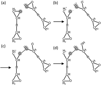
Before each cross-linking reaction, the distance between the available reactive atoms has been calculated, and the potential reactive atoms located inside the current reaction radius are recognized as shown in Fig. 3a. The reaction radius during the cross-linking process is set to be 3 Å initially with an increment of 0.5 Å. The maximum reaction radius is set to be 10 Å in this study, as the cross-linking process with a reaction radius over 10 Å usually results in a long equilibration process for alleviating the geometric distortions in the model. After the determination of reactive atoms, the epoxide groups comprising those recognized reactive atoms are open, as shown in Fig. 3b. The recognized reactive atoms are then connected to form cross-links (Fig. 3c). After the bond creation (cross-links being formed), the unreacted atoms at the open epoxide groups are saturated with hydrogen atoms (Fig. 3d). It is noticed that the combination of distance and energy criteria would require a lot of computational power in the iteration process. In addition, the computation using distance criteria is more straightforward and also requires less computational power, as shown from the various forcefield definitions. From this perspective, we decide to use the distance-based cross-linking approach, which is also well adopted by the various researchers.11,14,16 After each cross-linking reaction, the structural information is updated by introducing new bonds, angles, torsional angles, and improper angles into the cross-linked structure.
In order to relax the SU-8 structure after each cross-linking reaction, a combined equilibration process consisting of four steps is employed: (1) a 0.5 ps geometry optimization; (2) a 5 ps NVT ensemble equilibration; (3) a 5 ps NPT ensemble equilibration; (4) a 0.5 ps geometry optimization. During such equilibration process, the lengths of the newly created bonds are relaxed to the equilibrium value, which can alleviate the geometric distortions in the newly cross-linked structure. Within each reaction radius, the cross-linking reaction is performed at most three times or it stops if no reactive atoms are identified. The cross-linking process of SU-8 model is finished when the maximum reaction radius (10 Å) is achieved or all available potential reactive atoms are reacted.
Once the cross-linking process is finished, a short equilibration process is used to cool down the cross-linked structure until the room temperature (300 K) is reached. During the cooling process, the SU-8 model is first equilibrated in an NVT ensemble for 10 ps, and then in an NPT ensemble for another 10 ps. The equilibration process is performed at temperature of 368 K, 334 K and 300 K, respectively (i.e. a graduate change of temperature from elevated temperature to room temperature). Three SU-8 epoxy networks are built by performing the cross-linking process under the chosen forcefields separately.
Additional equilibration process
Though the cross-linked structure is equilibrated during the cross-linking process, the relatively short time frames used in the above equilibration processes are not sufficient for the epoxy network to reach the true equilibrium state. In order to achieve a fully relaxed molecular structure, the cross-linked SU-8 model is further equilibrated under some special conditions. Several groups have developed equilibration schemes with a control of temperature and pressure that can speed up the equilibration process and relief the residual stress inside the polymeric networks.34–36 Here, the equilibration scheme36 is used for equilibrating the cross-linked SU-8 epoxy network, which contains molecular dynamics simulations at high pressures to accelerate the compression of the cross-linked structure by overcoming the large energy barriers effectively. The details of the equilibration scheme are shown in Table 1, which consists of seven equilibration cycles under both NVT and NPT ensembles at 300 K. During the equilibration process, the density of the SU-8 model is adjusted through the pressure control. The pressure applied at the NPT simulation is gradually increased from atmospheric pressure to 50![[thin space (1/6-em)]](https://www.rsc.org/images/entities/char_2009.gif) 000 atm in the first three equilibration cycles (as indicated in Table 1) with a longer time frame (50–150 ps each) that allows an adequate relaxation inside the structure. The SU-8 epoxy network is compressed efficiently with a large pressure applied on the cross-linked structure. Then, the pressure is steadily reduced to 1 atm in the last four cycles (as indicated in Table 1) in a shorter time frame (5–15 ps each) in order to control the large pressure jumps. Along with the decrease of applied pressure, the cross-linked structure is decompressed accordingly. These compression and decompression steps only add a short period of time to the equilibration process, but they greatly improve the accuracy of the achieved densities.35,36 Finally, a 5 ns molecular relaxation under a constant temperature of 300 K and a constant pressure of 1 atm is carried out such that a fully equilibrated state can be achieved. By examining the root-mean-square displacement (RMSD) of the atoms, which keeps at a constant level before the 5 ns NPT equilibration run is completed, it implies that the equilibrated state has been obtained. After the equilibration process indicated in Table 1, the SU-8 epoxy network is further relaxed for 200 ps with a constant volume and temperature in the case of bulk modulus calculation, which is carried out under NVT ensemble as stated in the next section.
000 atm in the first three equilibration cycles (as indicated in Table 1) with a longer time frame (50–150 ps each) that allows an adequate relaxation inside the structure. The SU-8 epoxy network is compressed efficiently with a large pressure applied on the cross-linked structure. Then, the pressure is steadily reduced to 1 atm in the last four cycles (as indicated in Table 1) in a shorter time frame (5–15 ps each) in order to control the large pressure jumps. Along with the decrease of applied pressure, the cross-linked structure is decompressed accordingly. These compression and decompression steps only add a short period of time to the equilibration process, but they greatly improve the accuracy of the achieved densities.35,36 Finally, a 5 ns molecular relaxation under a constant temperature of 300 K and a constant pressure of 1 atm is carried out such that a fully equilibrated state can be achieved. By examining the root-mean-square displacement (RMSD) of the atoms, which keeps at a constant level before the 5 ns NPT equilibration run is completed, it implies that the equilibrated state has been obtained. After the equilibration process indicated in Table 1, the SU-8 epoxy network is further relaxed for 200 ps with a constant volume and temperature in the case of bulk modulus calculation, which is carried out under NVT ensemble as stated in the next section.
| Cycle | Ensemble | Temperature (K) | Pressure (atm) | Time frame (ps) |
|---|---|---|---|---|
| 1 | NVT | 300 | — | 100 |
| NPT | 300 | 1000 | 50 | |
| 2 | NVT | 300 | — | 150 |
| NPT | 300 | 30![[thin space (1/6-em)]](https://www.rsc.org/images/entities/char_2009.gif) 000 000 |
50 | |
| 3 | NVT | 300 | — | 150 |
| NPT | 300 | 50![[thin space (1/6-em)]](https://www.rsc.org/images/entities/char_2009.gif) 000 000 |
50 | |
| 4 | NVT | 300 | — | 150 |
| NPT | 300 | 25![[thin space (1/6-em)]](https://www.rsc.org/images/entities/char_2009.gif) 000 000 |
5 | |
| 5 | NVT | 300 | — | 15 |
| NPT | 300 | 5000 | 5 | |
| 6 | NVT | 300 | — | 15 |
| NPT | 300 | 500 | 5 | |
| 7 | NVT | 300 | — | 15 |
| NPT | 300 | 1 | 5000 |
Elastic modulus calculation
After the equilibration process, the Young's modulus (E) and bulk modulus (K) of the equilibrated SU-8 model are calculated by the uniaxial tensile deformations and the volumetric deformations, respectively. The shear modulus (G) and Poisson's ratio (ν) are computed by applying the linear elasticity theory.37 Due to the time scale limitation of MD simulations, the strain rates used in the dynamic deformations17,19,22 are much higher than that used in experiments. Previous MD studies report that the calculated Young's modulus in polymeric materials is not sensitive towards the change of strain rate, while the yield stress increases with the strain rate.19,22 In this study, it is expected that the elastic properties of SU-8 epoxy network are not influenced by the high strain rate. In the tensile deformation, the simulation cell along the loading direction X is elongated continuously with a strain rate of 1 × 10⁸ s−1, which is in a range typical for MD simulations, and the atmospheric pressure is maintained in the two transverse directions. The deformation is carried out at 300 K. At each deformation step, the SU-8 is deformed by 0.1% in strain followed by a 10 ps equilibration process before next deformation step. For all deformation processes, the SU-8 epoxy network is deformed by 3% in total. The virial stress tensors are monitored during the entire deformation process, and they are calculated using the eqn (2), where a and b denote values X, Y, Z to represent the six components of the symmetric tensor.
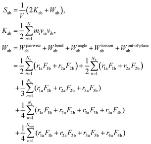 | (2) |
After the deformation, E of the SU-8 structure (i.e. the initial slope of the stress–strain curve) is determined, which is calculated by performing a regression analysis at the relatively linear portion of the stress–strain curve and is illustrated in eqn (3).
 | (3) |
Bulk modulus describes the material response under a uniform pressure. Here, it is determined by a volumetric deformation, in which equal axial strains in all three orthogonal directions are applied simultaneously. The calculation of bulk modulus is carried out at a constant temperature of 300 K. The dynamic deformations are applied in terms of dilatation by keeping the strain rate as 1 × 10⁸ s−1. The overall dilation of the SU-8 epoxy network is determined by ε = εXX + εYY + εZZ, where εXX, εYY and εZZ are the infinitesimal strain tensor components with respect to the coordinate directions X, Y and Z, respectively. The overall stress of the SU-8 epoxy network is calculated by σ = 1/3 (σXX + σYY + σZZ), where σXX, σYY and σZZ are the volume-averaged virial stress tensor components calculated by using eqn (2). K is then calculated as the initial slope of the curve representing the overall stress σ against the volumetric deformation ε as shown in eqn (4).
 | (4) |
G and ν are computed based on the calculated E and K by applying the linear elasticity theory.37 Assuming that the material is homogeneous and isotropic, with any two elastic constants available from direct measurements is considered to be sufficient for a full characterization of the mechanical properties. Particularly, the shear modulus G is given in eqn (5),
 | (5) |
 | (6) |
Results and discussions
The physical properties of SU-8 epoxy photoresist obtained from the MD simulations are compared with experimental data in Table 2.| CVFF | Dreiding | PCFF | Expt. | |
|---|---|---|---|---|
| Cross-linking degree (%) | 81.9 | 88.1 | 82.5 | ≥80 (ref. 38 and 39) |
| ρ (g cm−3) | 1.044 ± 0.002 | 1.050 ± 0.001 | 1.053 ± 0.002 | 1.07 ∼ 1.20 (ref. 32) |
| E (GPa) | 4.425 ± 0.230 | 4.422 ± 0.122 | 2.672 ± 0.160 | 2.70–4.02 (ref. 6−9) |
| K (GPa) | 4.350 ± 0.176 | 3.718 ± 0.149 | 2.876 ± 0.103 | 3.20 (ref. 7) |
| G (GPa) | 1.663 ± 0.106 | 1.698 ± 0.064 | 0.993 ± 0.070 | 1.20 (ref. 7) |
| ν | 0.330 ± 0.016 | 0.302 ± 0.013 | 0.345 ± 0.015 | 0.33 (ref. 7) |
Structural properties
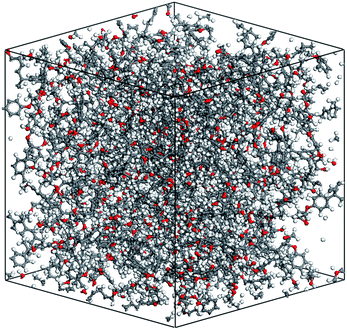
The cross-linking degree achieved after the polymerization process is an important parameter for evaluating the applicability of the cross-linking algorithm. It is defined as the ratio of the cross-linked reactive atoms divided by all the potential reactive atoms before the cross-linking process. One representative model of the highly cross-linked SU-8 epoxy network is shown in Fig. 4.The SU-8 atomistic model is obtained by carrying out the cross-linking algorithm without termination. The resulted cross-linking degree of the SU-8 epoxy network created by different forcefields is shown in Fig. 5. Initially, there are abundant reactive atoms available for the cross-linking reaction, which is indicated by a strong dependence between the cross-linking degree and the reaction radius. As the reaction goes on with an increasing reaction radius, less reactive atoms are available for the cross-linking reaction and thus, the curve becomes steady when the reaction radius is over 6 Å. The final cross-linking degree of all the constructed atomistic models is higher than 80%. Specifically, the SU-8 epoxy network constructed under Dreiding forcefield shows the maximum cross-linking degree of 88.1%, followed by 82.5% (PCFF) and 81.9% (CVFF). The influence of equilibration timespan on the maximum reaction radius and cross-linking degree is investigated by alternating the equilibration scheme before the cross-linking reaction. The final cross-linked structure from the CVFF simulation is chosen as an illustration. The cross-linked structure undergoes a 10 ns equilibration (5 ns NVT + 5 ns NPT) before the cross-linking process at a larger reaction radius. Another set of cross-linking process is performed using the original equilibration scheme (5 ps NVT + 5 ps NPT). The maximum reaction radius is found to be 11 Å for both cases, and the final cross-linking degree of the model after 10 ns equilibration is 85%, while the original model is 84%. Considering the large computational consumption and a limited improvement in terms of the cross-linking degree, current reaction radius range and equilibration process can be considered reasonable. Overall, the cross-linking algorithm used in this study is capable of constructing a highly cross-linked network close to those synthesized polymers through various experimental approaches.38,39
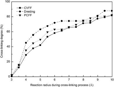 | ||
| Fig. 5 Cross-linking degree of SU-8 photoresist as a function of reaction radius under three forcefields. | ||
Density is another material parameter for evaluation. In the last 5 ns equilibration run under NPT ensemble as indicated in Table 1, the SU-8 epoxy network is equilibrated to reach the local minimal potential energy. The three orthogonal directions of the simulation cell are adjusted independently corresponding to the atmospheric pressure. The density of cross-linked SU-8 structure is sampled every 10 ps during this 5 ns equilibration process. In order to minimize the statistical error, only the recorded density from the final 2 ns equilibration run is accounted for the density calculation. The averaged density of the SU-8 epoxy network is shown in Table 2, with respect to the chosen forcefields. In comparison to the available value in the range of 1.07–1.20 g cm−3,32 underestimations of the density are observed from the three equilibrated SU-8 epoxy networks. The computed SU-8 ρ using the chosen forcefields are 1.044 ± 0.002 g cm−3 (CVFF), 1.050 ± 0.001 g cm−3 (Dreiding) and 1.053 ± 0.002 g cm−3 (PCFF). Compared with the available ρ range, the small discrepancies of the SU-8 epoxy networks demonstrate that the equilibration process as shown in Table 1 is effective to improve the accuracy of the densities achieved. The variations in ρ between the three SU-8 epoxy networks are less than 1%, which indicates that the potential function of the chosen forcefields are able to provide good mathematical approximations for calculating the potential energy of cross-linked SU-8 structure, which tends to equilibrate itself into a relaxed and equilibrium configuration. In view of the good agreement of ρ with experiments, the generated models of cross-linked SU-8 photoresist are regarded as reasonable structures close to those found in the real systems, which are used as bases in the following discussion.
Elastic properties
The stress–strain curves of cross-linked SU-8 epoxy network under the uniaxial tensile deformation are shown in Fig. 6. The stress along the loading direction shows a linear elastic response of SU-8 epoxy network during the whole deformation process. Young's modulus E is determined by performing a regression analysis on the stress–strain data from the 3% deformation. The computed E of SU-8 epoxy network under the chosen forcefields is reported in Table 2 with a comparison to the experimental data. The E obtained under CVFF and Dreiding forcefield are 4.425 ± 0.230 GPa and 4.422 ± 0.122 GPa, respectively, while a smaller value is yielded by PCFF of 2.672 ± 0.160 GPa. In view of the experimental tensile test results ranging from 2.70–4.02 GPa,6–9 the simulated E of the three SU-8 epoxy networks provide excellent agreements. Four other strain rates are examined in the tensile deformations under the chosen forcefields independently, including 1 × 10⁷ s−1, 5 × 10⁷ s−1, 5 × 10⁸ s−1 and 1 × 10⁹ s−1. The simulation results confirm that the Young's modulus is not sensitive towards the change of strain rate, which is consistent with the existing works from other similar epoxy systems.19,22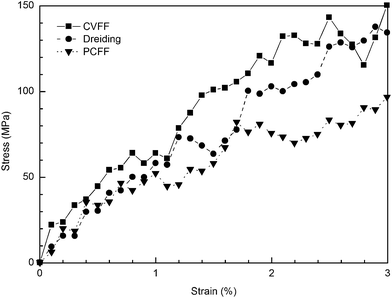 | ||
| Fig. 6 Stress–strain curves obtained at tensile deformation of cross-linked SU-8 photoresist under three forcefields. | ||
The K obtained for the SU-8 epoxy network under the chosen forcefields are 4.350 ± 0.176 GPa (CVFF), 3.718 ± 0.149 GPa (Dreiding) and 2.876 ± 0.103 GPa (PCFF), respectively. Using the reported E and G from experimental measurement,7 K is computed of 3.2 GPa by using the linear elasticity theory,37 and is the closet point of comparison for our data. Close agreements are observed between the reference data and the three predictions.
G and ν computed by applying the linear elasticity theory are compared with the experimental measurements at 300 K, as shown in Table 2. The G of the SU-8 epoxy network under CVFF and Dreiding are greater than the reported data (1.20 GPa), with values of 1.663 ± 0.106 GPa and 1.698 ± 0.064 GPa, respectively, while a smaller value of 0.993 ± 0.070 GPa is observed in the case of PCFF. Nevertheless, the order of magnitude is the same between these values.
In the meantime, a good agreement is found between the computed ν (0.330 ± 0.016) under CVFF and the experimental value (0.33), while the values for other two forcefields are 0.302 ± 0.013 (Dreiding) and 0.345 ± 0.015 (PCFF), which are also in reasonable accord.
Conclusions
In this study, MD investigations on the cross-linking and physical properties of SU-8 epoxy photoresist are performed under three chosen forcefields (i.e. CVFF, Dreiding and PCFF). Using an effective dynamic cross-linking algorithm, three SU-8 epoxy networks are constructed with cross-linking degrees higher than 80%. After equilibration process incorporating high pressure control, the densities of the cross-linked structure are adjusted to levels corresponding to the existing value. Elastic properties of the equilibrated SU-8 photoresists are measured by means of computational dynamic deformations. The calculated mechanical properties of the constructed SU-8 epoxy network are in accord with the various experimental observables, including Young's modulus, bulk modulus, shear modulus and Poisson's ratio.Our dynamic cross-linking algorithm is believed to be applicable to general cross-linked epoxy-based materials which under homopolymerization. The physical properties obtained in this study demonstrate the high Young's modulus of SU-8 photoresist, which is favorable in engineering applications from nano- to micro-scale. It is envisioned that our work will be beneficial to the design, synthesis and applications of epoxy-based materials, especially the predictions of structural stability and long term material performance.
Acknowledgements
The authors are grateful to the support from Croucher Foundation through the Start-up Allowance for Croucher Scholars with the Grant no. 9500012, and the support from the Research Grants Council (RGC) in Hong Kong through the Early Career Scheme (ECS) with the Grant no. 139113.References
- E. H. Conradie and D. F. Moore, J. Micromech. Microeng., 2002, 12, 368 CrossRef CAS.
- R. D. Adams, J. Comyn and W. C. Wake, Structural adhesive joints in engineering, Springer, 1997 Search PubMed.
- C. E. Browning and J. M. Whitney, in Fillers and Reinforcements for Plastics, American Chemical Society, 1974, vol. 134, pp. 137–148 Search PubMed.
- A. d. Campo and C. Greiner, J. Micromech. Microeng., 2007, 17, R81 CrossRef.
- C. Ishiyama and Y. Higo, J. Polym. Sci., Part B: Polym. Phys., 2002, 40, 460–465 CrossRef CAS.
- H. Lorenz, M. Despont, N. Fahrni, N. LaBianca, P. Renaud and P. Vettiger, J. Micromech. Microeng., 1997, 7, 121 CrossRef CAS.
- R. Feng and R. J. Farris, J. Mater. Sci., 2002, 37, 4793–4799 CrossRef CAS.
- R. Feng and R. J. Farris, J. Micromech. Microeng., 2003, 13, 80 CrossRef CAS.
- J. Hammacher, A. Fuelle, J. Flaemig, J. Saupe, B. Loechel and J. Grimm, Microsyst. Technol., 2008, 14, 1515–1523 CrossRef CAS PubMed.
- I. Hamerton, C. R. Heald and B. J. Howlin, J. Mater. Chem., 1996, 6, 311–314 RSC.
- D. C. Doherty, B. N. Holmes, P. Leung and R. B. Ross, Comput. Theor. Polym. Sci., 1998, 8, 169–178 CrossRef CAS.
- I. Yarovsky and E. Evans, Polymer, 2002, 43, 963–969 CrossRef CAS.
- D. R. Heine, G. S. Grest, C. D. Lorenz, M. Tsige and M. J. Stevens, Macromolecules, 2004, 37, 3857–3864 CrossRef CAS.
- C. Wu and W. Xu, Polymer, 2006, 47, 6004–6009 CrossRef CAS PubMed.
- J. L. Tack and D. M. Ford, J. Mol. Graphics Modell., 2008, 26, 1269–1275 CrossRef CAS PubMed.
- V. Varshney, S. S. Patnaik, A. K. Roy and B. L. Farmer, Macromolecules, 2008, 41, 6837–6842 CrossRef CAS.
- C. Li and A. Strachan, Polymer, 2010, 51, 6058–6070 CrossRef CAS PubMed.
- A. Bandyopadhyay, P. K. Valavala, T. C. Clancy, K. E. Wise and G. M. Odegard, Polymer, 2011, 52, 2445–2452 CrossRef CAS PubMed.
- C. Li and A. Strachan, Polymer, 2011, 52, 2920–2928 CrossRef CAS PubMed.
- N. Nouri and S. Ziaei-Rad, Macromolecules, 2011, 44, 5481–5489 CrossRef CAS.
- N. B. Shenogina, M. Tsige, S. S. Patnaik and S. M. Mukhopadhyay, Macromolecules, 2012, 45, 5307–5315 CrossRef CAS.
- S. Yang and J. Qu, Polymer, 2012, 53, 4806–4817 CrossRef CAS PubMed.
- O. Sindt, J. Perez and J. F. Gerard, Polymer, 1996, 37, 2989–2997 CrossRef CAS.
- P. Dauber-Osguthorpe, V. A. Roberts, D. J. Osguthorpe, J. Wolff, M. Genest and A. T. Hagler, Proteins: Struct., Funct., Bioinf., 1988, 4, 31–47 CrossRef CAS PubMed.
- J. R. Maple, U. Dinur and A. T. Hagler, Proc. Natl. Acad. Sci. U. S. A., 1988, 85, 5350–5354 CrossRef CAS.
- S. L. Mayo, B. D. Olafson and W. A. Goddard, J. Phys. Chem., 1990, 94, 8897–8909 CrossRef CAS.
- H. Sun, Macromolecules, 1995, 28, 701–712 CrossRef CAS.
- T. Oie, G. M. Maggiora, R. E. Christoffersen and D. J. Duchamp, Int. J. Quantum Chem., 1981, 20, 1–47 CrossRef.
- A. K. Rappe and W. A. Goddard III, J. Phys. Chem., 1991, 95, 3358–3363 CrossRef CAS.
- Accelrys Software Inc.: Materials Studio.
- S. Plimpton, J. Comput. Phys., 1995, 117, 1–19 CrossRef CAS.
- MicroChem.
- D. N. Theodorou and U. W. Suter, Macromolecules, 1985, 18, 1467–1478 CrossRef CAS.
- D. Hofmann, L. Fritz, J. Ulbrich, C. Schepers and M. Böhning, Macromol. Theory Simul., 2000, 9, 293–327 CrossRef CAS.
- G. S. Larsen, P. Lin, K. E. Hart and C. M. Colina, Macromolecules, 2011, 44, 6944–6951 CrossRef CAS.
- L. J. Abbott, K. E. Hart and C. M. Colina, Theor. Chem. Acc., 2013, 132, 1–19 CrossRef CAS.
- L. D. Landau, E. Lifshitz, J. Sykes, W. Reid and E. H. Dill, Phys. Today, 2009, 13, 44–46 CrossRef PubMed.
- C. Hirschl, M. Biebl–Rydlo, M. DeBiasio, W. Mühleisen, L. Neumaier, W. Scherf, G. Oreski, G. Eder, B. Chernev and W. Schwab, Sol. Energy Mater. Sol. Cells, 2013, 116, 203–218 CrossRef CAS PubMed.
- B. S. Chernev, C. Hirschl and G. C. Eder, Appl. Spectrosc., 2013, 67, 1296–1301 CrossRef CAS PubMed.
Footnote |
| † Electronic supplementary information (ESI) available. See DOI: 10.1039/c4ra04298k |
| This journal is © The Royal Society of Chemistry 2014 |

