 Open Access Article
Electrochemical-catalytic NH3 synthesis from H2O and N2 using an electrochemical cell with a Ru catalyst, Pd–Ag membrane cathode, and NaOH–KOH molten salt electrolyte at 250 °C†
Raisei
Sagara
,
Rika
Hayashi
,
Aika
Hirata
,
Shintaroh
Nagaishi
and
Jun
Kubota
 *
*
Department of Chemical Engineering, Fukuoka University, 8-19-1, Nanakuma, Jonan-ku, Fukuoka 814-0180, Japan. E-mail: jkubota@fukuoka-u.ac.jp
First published on 20th May 2024
Abstract
Using sustainable energy-based electricity to synthesize NH3 from H2O and N2 to release O2 not only contributes to making chemical fertilizer production carbon neutral, but also holds promise for the use of NH3 as a fuel. NH3 synthesis from water and nitrogen was conducted at around 250 °C and below 1.0 MPa by combining a molten salt electrolyte of NaOH–KOH, a Pd alloy hydrogen-permeable membrane cathode, a Ni anode, and a Ru-based catalyst on the cathode backside. The rate and current efficiency for NH3 formation were obtained as 11 nmol s−1 cm−2 (38 μmol h−1 cm−2) and 25%, respectively, at 30 mA cm−2, 1.0 MPa, and 250 °C. It was confirmed that the remaining percentage from the 100% current efficiency for NH3 production was attributed to the current efficiency for H2 production. The cell voltage was as low as 1.47 V at 30 mA cm−2 and increased to 1.95 V at 100 mA cm−2. The potential of this electrochemical system is discussed.
Introduction
Ammonia (NH3) not only supports human food production as a synthetic fertilizer itself or as its raw materials, but also holds promise as a carbon-free fuel when obtained from renewable energy sources.1–3 At present, the most reliable methods for obtaining large amounts of renewable energy involve using photovoltaics, solar thermal, wind power, etc.4 However, in advanced countries, surplus electricity from these sources is already being generated, leading to situations where it is shut down.5,6 It is important to convert this electricity into chemical energy carriers and store it for use at times and places when humans need it.7,8 Therefore, a huge number of research studies have been conducted on electrochemical reduction of nitrogen to produce NH39–13 and electrochemical reduction of CO2 to produce hydrocarbons.14,15However, while the electrochemical reduction of CO2 to CO is approaching practical efficiency,14 the production of NH3via electrochemical reduction of N216 and the production of hydrocarbons or alcohols via electrochemical reduction of CO215 are not considered to have reached practical levels due to low current efficiency and significant overpotentials. The most promising electrochemical method for obtaining ammonia is the lithium-mediated method, but the use of metallic lithium is expected to require a very large overpotential.16,17
It is possible to produce NH3 from electricity by utilizing water electrolysis for hydrogen production and the conventional Haber–Bosch process.18 This approach has been attempted since the early stages of NH3 synthesis.18 However, large-scale chemical plants like the Haber–Bosch process face challenges in operating under fluctuating conditions, making it difficult to integrate with highly variable sources of energy, such as solar and wind power. As a result, complex and expensive systems including hydrogen storage become necessary. If NH3 could be directly obtained from water and nitrogen within a single electrochemical device, not only would the thermodynamic energy requirements be reduced, but also the system could be operated solely with easy start–stop controls, eliminating the need for hydrogen storage.
Our group has been addressing the synthesis of NH3 from H2O and N2 using phosphate-based electrolytes, a composite of CsH2PO4 and SiP2O7, suitable for operation at temperatures between 200 and 250 °C.19,20 In this temperature range, phosphate electrolytes are effective for synthesizing various molecules.21–25 The distinguishing feature of our technology lies not in electrochemically reducing nitrogen, but in catalytically activating nitrogen, which is then hydrogenated by hydrogen obtained from water electrolysis.21 Our goal is not to discover a new chemical phenomenon of direct electrochemical reduction of nitrogen as fundamental research, but to find out how to produce ammonia efficiently and easily from water and nitrogen using electricity. To achieve this, it is necessary to form a catalytic layer with two distinct functionalities: one portion exposed to the gas phase without being immersed in the electrolyte, and another portion that performs proton reduction in contact with the electrolyte. For this purpose, we devised an electrolysis cell with a Pd–Ag alloy hydrogen-permeable membrane interfacing with the electrolyte as the cathode, while a Ru-based catalyst for NH3 synthesis is placed on the backside of the Pd–Ag membrane.19,20 The hydrogen-permeable membrane prevents the electrolyte from permeating into the Ru-based catalyst for NH3 synthesis, avoiding the absorption of the generated NH3 into the electrolyte and contamination of introduced steam into NH3. Therefore, even unstable catalysts prone to dissolution when in contact with high-temperature electrolytes can be used reliably. Furthermore, mechanical support by the Pd–Ag alloy hydrogen-permeable membrane facilitates operation under pressure, up to 1.0 MPa. Even if spanning a two-step reaction pathway involving hydrogen formation and nitrogen hydrogenation, the production of NH3 and oxygen from water and nitrogen within a single-temperature electrochemical device maintains thermodynamic favorability similar to the electrochemical reduction of nitrogen.19,20 In other words, the exothermic heat generated by the hydrogenation of N2 to form NH3 can be utilized for the endothermic process of water electrolysis. Furthermore, it offers practical advantages such as eliminating the need for hydrogen storage and simplifying device start–stop procedures. However, it has been noted that in systems operating at over 60 mA cm−2 with this CsH2PO4/SiP2O7 electrolyte, the overpotential gradually increases, leading to degradation of the anode.20
Phosphate electrolytes have been studied with the expectation of being a practical electrolyte, given the commercialization of phosphoric acid fuel cells (PAFCs) operating at around 200 °C.26,27 However, large-scale water electrolysis predominantly utilizes alkaline water electrolysis (AWE) at temperatures below 100 °C.28,29 There is hope for the application of this electrolyte in NH3 synthesis by raising the temperature range to between 200 and 250 °C.30–32 NaOH and KOH form eutectic salts with a melting point of around 160 °C, which allows them to be used as molten salt electrolytes at temperatures above 200 °C.33–36 With sufficient humidification, steam can undergo dissolution in the molten salt resembling a concentrated alkaline solution.33–36 Phosphate electrolytes are in a semi-solid state at the operating temperatures, and while the usefulness of solid electrolytes is evident in fuel cells because the gas-phase network and three-phase interfaces for rapidly diffusing gaseous reactants to the electrode layer are crucial, their advantages seem not to be significant in water electrolysis. This is because the products are gaseous and are evolved as bubbles even in liquid electrolytes, and the superiority of solid electrolytes is not significant. Therefore, there is potential for liquid electrolytes such as molten salts as well. Unlike acidic ion exchange membranes used in proton exchange membrane electrolysis, alkaline electrolytes like NaOH–KOH allow for the use of non-noble metals such as Ni as electrode catalysts, which is another advantage.28,29 In this study, we investigated NH3 synthesis using a Pd–Ag hydrogen-permeable membrane cell with an electrolyte consisting of NaOH–KOH. There were past attempts at NH3 synthesis using hydroxide molten salts, but none have reliably achieved nitrogen reduction.37,38 Separating the functions of water electrolysis and nitrogen activation/hydrogenation, it is demonstrated that hydroxide melts can be applied to NH3 synthesis in this work. The characteristics and practicality of NH3 synthesis from water and nitrogen using alkaline electrolytes were discussed.
Experimental
The sectional drawing of a hydrogen-permeable membrane electrochemical cell for NH3 synthesis with an NaOH–KOH molten salt electrolyte is illustrated in Fig. 1. The main components of the electrochemical cell included a catalyst powder of Ru/Cs+/C weighing 0.20 g, a Pd–Ag membrane (3![[thin space (1/6-em)]](https://www.rsc.org/images/entities/char_2009.gif) :
:![[thin space (1/6-em)]](https://www.rsc.org/images/entities/char_2009.gif) 1 atomic ratio) with a thickness of 100 μm, an NaOH–KOH aqueous solution with a 1
1 atomic ratio) with a thickness of 100 μm, an NaOH–KOH aqueous solution with a 1![[thin space (1/6-em)]](https://www.rsc.org/images/entities/char_2009.gif) :
:![[thin space (1/6-em)]](https://www.rsc.org/images/entities/char_2009.gif) 1 molar ratio, and Ni foam with a diameter of 10 mm and a thickness of 1 mm on a Ni disk with a diameter of 10 mm and a thickness of 5 mm. The major differences from previous phosphate electrolyte electrochemical cells are that the material of the anode vessel has been changed from Ti to polytetrafluoroethylene (PTFE), and the material of the anode has been changed from Pt to Ni metal. The gap between the end faces of the cathode and anode was set to 3 mm. After assembling the anode and cathode vessels of the electrochemical cell, 5.0 mL of NaOH–KOH solution was introduced into the cell using a syringe with a narrow tube connected to the gas tube. The NaOH–KOH solution was a mixture of 0.20 mol of NaOH, 0.20 mol of KOH, and 20 mL of H2O.
1 molar ratio, and Ni foam with a diameter of 10 mm and a thickness of 1 mm on a Ni disk with a diameter of 10 mm and a thickness of 5 mm. The major differences from previous phosphate electrolyte electrochemical cells are that the material of the anode vessel has been changed from Ti to polytetrafluoroethylene (PTFE), and the material of the anode has been changed from Pt to Ni metal. The gap between the end faces of the cathode and anode was set to 3 mm. After assembling the anode and cathode vessels of the electrochemical cell, 5.0 mL of NaOH–KOH solution was introduced into the cell using a syringe with a narrow tube connected to the gas tube. The NaOH–KOH solution was a mixture of 0.20 mol of NaOH, 0.20 mol of KOH, and 20 mL of H2O.
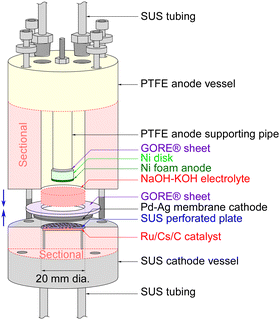 | ||
| Fig. 1 Sectional drawing of the hydrogen-permeable membrane electrochemical cell for NH3 synthesis with an NaOH–KOH molten salt electrolyte. | ||
The cathode of the Pd–Ag membrane had a contacting area of 3.1 cm2 to the electrolyte, and the anode of the Ni foam disk had a geometric area of 0.79 cm2. In this paper, the current density was defined relative to the cathode area, taking into account the uncertainty in the practical area of the Ni foam anode at the electrolyte interface. Due to length restrictions in the communication, the synthesis details of Ru/Cs+/C have been provided in our previous paper and the ESI,† for this article. Additionally, methods for detecting generated NH3 or H2, cell heating techniques, gas supply methods, and ways to increase cell pressure can be referenced in our previous papers or the ESI† of this paper. It should be noted that the flow rate of N2 was optimized for maximizing NH3 production, resulting in an H2/N2 ratio of 0.070 against current density.19,20
Results and discussion
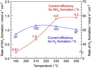
The rates of NH3 and H2 formation for NH3 synthesis from H2O and N2 with varying temperature are plotted in Fig. 2. The current efficiencies for the respective rates are also provided in Fig. 2. The current efficiencies for the formation of NH3 and H2, CENH3 and CEH2, respectively, were defined as follows. | (1) |
 | (2) |
![[thin space (1/6-em)]](https://www.rsc.org/images/entities/char_2009.gif) 485 C mol−1 and current density in A cm−2. The product of the ratio of the thermoneutral potential of 1.32 V to the actual cell voltage and the current efficiency is the energy conversion efficiency, which is a critically important factor in energy conversion technologies.
485 C mol−1 and current density in A cm−2. The product of the ratio of the thermoneutral potential of 1.32 V to the actual cell voltage and the current efficiency is the energy conversion efficiency, which is a critically important factor in energy conversion technologies.
The current efficiency for NH3 synthesis was obtained as 4.0–4.2% at 230–250 °C. This efficiency was similar to our previous papers. The theoretical limit of current efficiency for NH3 formation at 250 °C under this N2 flow condition was derived as 6.4% from the thermodynamical equilibrium among NH3, H2, and N2.19,20 The attainment of equilibrium was estimated to be 65% at 250 °C. The fact that there is little difference in the rate of NH3 formation between 230 °C and 250 °C suggests that at 250 °C, the catalytic reaction is not limiting the rate, and the rate of NH3 formation is constrained by the equilibrium. The decrease in NH3 formation rate below 210 °C is attributed to insufficient catalytic reaction rates. The current efficiency for H2 formation exceeded 100%, and when the sum of the current efficiencies of ammonia production and hydrogen production was calculated, it was approximately 100%.
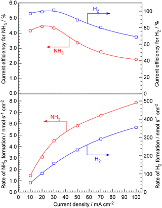
The advantage of NaOH–KOH electrolyte is its ability to maintain stability and conduct long-term experiments at a relatively high current density of 100 mA cm−2. In our conventional system using phosphate electrolytes, when the current density exceeds 50 mA cm−2, the cell voltage starts to rise within a few hours, leading to deterioration. The rates of NH3 and H2 formation for NH3 synthesis from H2O and N2, along with their current efficiencies, are depicted in Fig. 3 as a function of current density up to 100 mA cm−2. Exceeding a current density of 100 mA cm−2 was not possible due to limitations in the capacity of the power supply. The rates of NH3 and H2 formation increased monotonically with increasing current density. Looking at the current efficiency, between 10 and 30 mA cm−2, both the current efficiency for NH3 formation and for H2 formation remain almost constant. However, when the current density is increased beyond 50 mA cm−2, it becomes evident that both the current efficiency for NH3 formation and for H2 formation decrease.
The decrease in current efficiency for NH3 formation at high current densities can be understood as insufficient catalytic activity. In such cases, the current efficiency for H2 formation must increase by the amount that the current efficiency for NH3 formation decreases. The most likely cause of both the current efficiency for NH3 and H2 formation decreasing, resulting in a decrease in overall current efficiency, is the O2 generated at the anode either being reduced at the cathode by passing through the electrolyte or the hydrogen reduced at the cathode being unable to be absorbed by the Pd–Ag membrane and instead released as H2 molecules in the electrolyte, subsequently oxidizing at the anode. The issue of such cross-leakage becoming problematic under high current densities was already recognized in our previous studies using phosphate electrolytes,20 and it became pronounced even with NaOH–KOH electrolytes. Particularly in liquid electrolytes such as molten salts, cross-leakage poses a serious problem, as the evolved gases might pass through the electrolyte as bubbles or absorbed gases between the anode and cathode. Therefore, it seems necessary to explore measures such as optimizing the electrode spacing and installing separators with semi-permeable membranes.
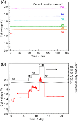
Next, the results of time-dependent changes in cell voltage during NH3 synthesis at constant current are shown in Fig. 4A for various current densities. At 10 mA cm−2, the cell voltage was about 1.28 V, which was between the equilibrium potential (1.16 V at 250 °C) and thermoneutral potential (1.32 V at 250 °C). With increasing current densities, cell voltage was increased to 1.96 V at 100 mA cm−2. At any current density, the cell voltage remained nearly constant over a period of 3 h, exhibiting remarkable stability. Fig. 4B shows the cell voltage changes in an operation for 3 weeks. While minor fluctuations in cell voltage were observed, there were no noticeable voltage increases indicative of degradation. The catalyst is inherently non-degrading, so consistent NH3 production was observed at any given point as long as water electrolysis continued at the stated current density. This was a highly favourable outcome compared to cells using phosphate electrolytes, as demonstrated in our previous papers, where an increase in cell voltage was observed within several hours at current densities exceeding 50 mA cm−2.
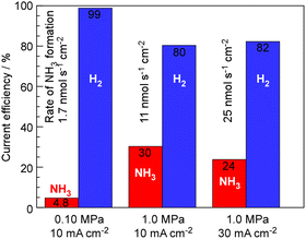
The synthesis of NH3 by this system is strongly limited by chemical equilibrium, and theoretically, at a pressure of 0.10 MPa, temperature of 250 °C, and the present ratio between N2 and current density, only up to 6.4% current efficiency of NH3 can be expected. To relax the constraints of equilibrium, lowering the temperature while increasing the pressure is an option; however, as shown in Fig. 2, reducing the temperature shifts the limitation from equilibrium to kinetic, resulting in a decrease in the rate of NH3 formation. Therefore, the results of investigating the rate of NH3 formation when increasing the total pressure are shown in Fig. 5. At 1.0 MPa and 250 °C, the theoretical limit is estimated to be 36%.19,20 As shown in Fig. 5, while the current efficiency for NH3 formation was 4.76%, at 0.10 MPa, 10 mA cm−2 and 250 °C, it was increased to 30% with elevating the pressure to 1.0 MPa. For 30 mA cm−2 current density at 1.0 MPa and 250 °C, the current efficiency for NH3 formation decreased to 25% because of insufficient catalytic activity.
The results of this study show that, unsurprisingly, the current efficiency of NH3 production was very similar to the values obtained in our previous research, as the catalyst layer used was the same.19,20 However, the significant advantage lies in the stable operation at higher current densities and the absence of observations such as electrode degradation. An important point not to overlook is that concentrated alkaline electrolytes, being strong alkalis, do not absorb NH3. In previous electrochemical cells using phosphate-based electrolytes, the use of a Pd–Ag membrane was imperative as it prevented the absorption of NH3 by the protonic electrolyte and the subsequent neutralization of the electrolyte.19,20 If the electrolyte does not absorb NH3, it might be possible to use hydrophobic filters instead of Pd–Ag membranes, as in the synthesis of methane from CO2 and water using acidic phosphate electrolytes in this electrochemical system.22 Alkaline water electrolysis conducted in aqueous solutions below 100 °C is considered crucial for hydrogen production in a hydrogen energy society. By increasing the operating temperature to around 250 °C, it is conceivable to synthesize NH3 and produce various other fuel substances and useful materials.
Conclusions
With KOH–NaOH eutectic molten salt electrolytes, an electrochemical-catalytic cell for NH3 synthesis from nitrogen and water was studied at 250 °C and 1.0 MPa. The current efficiency for NH3 formation was achieved to 30%, and the residue was used for H2 formation. The cell voltage was extremely stable up to 100 mA cm−2, and no corrosion of the electrodes or components was observed, suggesting that this study shows significant potential for obtaining ammonia from water and nitrogen using electricity.Author contributions
Sagara primarily contributed to the investigation, which included experimental work, analysis of the obtained data, and paper writing. Hayashi, Hirata, and Nagaishi were primarily involved in practical experimental works and data analysis. Kubota played multifaceted roles including supervision in this study.Conflicts of interest
There are no conflicts to declare.Acknowledgements
This article is based on results obtained from a project, JPNP14004, “Highly-efficient NH3 electrochemical synthesis technology from renewable energy electricity (FY2022-2023)”, commissioned by the New Energy and Industrial Technology Development Organization (NEDO), Japan.References
- CO2 free ammonia as an energy carrier: Japan's insights, ed. K. Aika and H. Kobayashi, Springer Nature, Singapore, 2023 Search PubMed.
- International Energy Agency, Ammonia Technology Roadmap, 2021 Search PubMed.
- International Renewable Energy Agency, Innovation Outlook: Renewable Ammonia, 2022, ISBN: 978-92-9260-423-3 Search PubMed.
- International Energy Agency, Renewables, 2023, Analysis and forecast to 2028, 2023.
- California ISO, Wind and solar curtailment totals by month, https://www.caiso.com/informed/Pages/ManagingOversupply.aspx.
- D. Kim, Z. Wang, J. Brugger, D. Blum, M. Wetter, T. Hong and M. A. Piette, Appl. Energy, 2022, 321, 119343 CrossRef.
- R. Daiyan, I. MacGill and R. Amal, ACS Energy Lett., 2020, 5, 3843–3847 CrossRef CAS.
- J. Gong, N. J. English, D. Pant, G. R. Patzke, S. Protti and T. Zhang, ACS Sustainable Chem. Eng., 2021, 9, 7179–7181 CrossRef CAS.
- C. R. Santhosh and R. Sankannavar, Appl. Energy, 2023, 352, 121960 CrossRef CAS.
- B. Wang, T. Li, F. Gong, M. H. D. Othman and R. Xiao, Fuel Process. Technol., 2022, 235, 107380 CrossRef CAS.
- G. Qing, R. Ghazfar, S. T. Jackowski, F. Habibzadeh, M. M. Ashtiani, C.-P. Chen, M. R. Smith III and T. W. Hamann, Chem. Rev., 2020, 120, 5437–5516 CrossRef CAS PubMed.
- A. J. Martín, T. Shinagawa and J. Pérez-Ramírez, Chem, 2019, 5, 263–283 Search PubMed.
- I. A. Amar, R. Lan, C. T. G. Petit and S. Tao, J. Solid State Electrochem., 2011, 15, 1845–1860 CrossRef CAS.
- S. Garg, M. Li, A. Z. Weber, L. Ge, L. Li, V. Rudolph, G. Wang and T. E. Rufford, J. Mater. Chem. A, 2020, 8, 1511–1544 RSC.
- M. Gattrell, N. Gupta and A. Co, J. Electroanal. Chem., 2006, 594, 1–19 CrossRef CAS.
- S. Z. Andersen, V. Čolić, S. Yang, J. A. Schwalbe, A. C. Nielander, J. M. McEnaney, K. Enemark-Rasmussen, J. G. Baker, A. R. Singh, B. A. Rohr, M. J. Statt, S. J. Blair, S. Mezzavilla, J. Kibsgaard, P. C. K. Vesborg, M. Cargnello, S. F. Bent, T. F. Jaramillo, I. E. L. Stephens, J. K. Nørskov and I. Chorkendorff, Nature, 2019, 570, 504–508 CrossRef CAS PubMed.
- M. I. Ahmed, A. Assafiri, D. B. Hibbert and C. Zhao, Small, 2023, 2305616 CrossRef CAS PubMed.
- A. Valera-Medina, F. Amer-Hatem, A. K. Azad, I. C. Delouse, M. de Joannon, R. X. Fernandes, P. Glarborg, H. Hashemi, X. He, S. Mashruk, J. McGowan, C. Mounaim-Rouselle, A. Ortiz-Prado, A. Ortiz-Valera, I. Rossetti, B. Shu, M. Yehia, H. Xiao and M. Costa, Energy Fuels, 2021, 35, 6964–7029 CrossRef CAS.
- K. Imamura and J. Kubota, Sustainable Energy Fuels, 2019, 3, 1406–1417 RSC.
- S. Nagaishi, R. Hayashi, A. Hirata, R. Sagara and J. Kubota, Sustainable Energy Fuels, 2024, 8, 914–926 RSC.
- E. Christensen, R. W. Berg, R. Krüger and N. J. Bjerrum, J. Electrochem. Soc., 2023, 170, 014502 CrossRef CAS.
- J. Kubota, T. Okumura and R. Hayashi, Sustainable Energy Fuels, 2022, 6, 1362–1372 RSC.
- N. Fujiwara, S. Tada and R. Kikuchi, iScience, 2022, 25, 105381 CrossRef CAS PubMed.
- Y. Yuan, S. Tada and R. Kikuchi, Sustainable Energy Fuels, 2022, 6, 458–465 RSC.
- G. Qing, R. Kikuchi, S. Kishira, A. Takagaki, T. Sugawara and S. T. Oyama, J. Electrochem. Soc., 2016, 163, E282–E287 CrossRef CAS.
- T. F. Fuller and K. G. Gallagher, in Phosphoric acid fuel cells, Materials for Fuel Cells, ed. M. Gasik, Elsevier B.V., 2008, ch. 6 Search PubMed.
- P. M. Parker, The 2023 Report on Phosphoric Acid Fuel Cells: World Market Segmentation by City, ICON Group International, Inc., 2022 Search PubMed.
- S. Kumar and H. Lim, Energy Rep., 2022, 8, 13793–13813 CrossRef.
- K. Zeng and D. Zhang, Prog. Energy Comb. Sci., 2010, 36, 307–326 CrossRef CAS.
- K. Kawaguchi, K. Goto, A. Konno and T. Nohira, J. Electrochem. Soc., 2023, 170, 084507 CrossRef.
- F. P. Lohmann-Richters, S. Renz, W. Lehnert, M. Müller and M. Carmo, J. Electrochem. Soc., 2021, 168, 114501 CrossRef CAS.
- S. D. Ebbesen, S. H. Jensen, A. Hauch and M. B. Mogensen, Chem. Rev., 2014, 114, 10697–10734 CrossRef CAS PubMed.
- E. Al-Muslih, P. J. Iredale and J. K. Maund, J. Chem. Eng. Data, 1983, 28, 245–246 CrossRef CAS.
- Solubility Data Series, Gases in Molten Salts, ed. J. W. Lorimer, International Union of Pure and Applied Chemistry (IUPAC), Pergamon Press, 1989, vol. 45/46 Search PubMed.
- H. W. Otto and R. P. Seward, J. Chem. Eng. Data, 1964, 9, 507–508 CrossRef CAS.
- J. Yang, H. Muroyama, T. Matsui and K. Eguchi, J. Power Sources, 2014, 245, 277–282 CrossRef CAS.
- S. Licht, B. C. Cui, B. H. Wang, F. F. Li, J. Lau and S. Z. Liu, Science, 2014, 345, 637–640 CrossRef CAS PubMed.
- G. Chehade and I. Dincer, Int. J. Energy Res., 2020, 44, 7183–7197 CrossRef CAS.
Footnote |
| † Electronic supplementary information (ESI) available. See DOI: https://doi.org/10.1039/d4ya00218k |
| This journal is © The Royal Society of Chemistry 2024 |

