Cascading responses of stimuli-responsive materials
Yuya
Oaki
 *a and
Syuji
Fujii
 *b
*b
aDepartment of Applied Chemistry, Faculty of Science and Technology, Keio University, 3-14-1 Hiyoshi, Kohoku-ku, Yokohama 223-8522, Japan. E-mail: oakiyuya@applc.keio.ac.jp
bDepartment of Applied Chemistry, Faculty of Engineering, Osaka Institute of Technology, 5-16-1 Omiya, Asahi-ku, Osaka 535-8585, Japan. E-mail: syuji.fujii@oit.ac.jp
First published on 19th July 2024
Abstract
Responsiveness to stimuli is important in daily life: natural biological activity is governed by continuous stimulus responsiveness. The design of stimuli-responsive materials is required for the development of advanced sensing systems. Although fully controlled stimuli-responsive systems have been constructed in nature, artificial systems remain a challenge. Conventional stimuli-responsive materials show direct responsiveness to an applied stimulus (Stimulus 1), with structural changes in their molecules and organized states. This feature article focuses on cascading responses as a new concept for integrating stimuli-responsive material design. In cascading responses, an original stimulus (Stimulus 1) is converted into other stimuli (Stimulus 2, 3, …, N) through successive conversions. Stimulus N provides the eventual output response. Integration of multiple stimuli-responsive materials is required to achieve cascading responses. Although cascade, domino, and tandem chemical reactions have been reported at the molecular level, they are not used for materials with higher organized structures. In this article, we introduce functional carriers and sensors based on cascading responses as model cases. The concept of cascading responses enables the achievement of transscale responsivity and sensitivity, which are not directly induced by the original stimulus or its responsive material, for the development of advanced dynamic functional materials.
1. Introduction
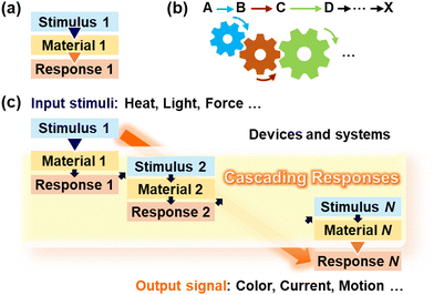
Stimuli-responsive materials have been studied in the fields of chemistry and materials science.1–15 The design of their molecules and self-assemblies aid in the development of various applications, including carriers, sensors, and actuators. Generally, molecules, materials, and devices are designed to achieve responsiveness to a specific targeted stimulus, such as a chemical or physical stress. Microscopic structural changes in molecules and materials in response to stimuli induce macroscopic responsiveness, such as changes in visible color, fluorescent color, conductivity, and shape. In this process, an input stimulus (Stimulus 1) directly induces an output response (Response 1) (Fig. 1a). Although such single-type stimulus responsiveness contributes to the development of new materials and devices, the responsivity of the applied stimuli, such as the type, intensity range, and length scale, is still limited. In the present article, we focus on cascading responses, which are distinguishable from conventional single responses (Fig. 1c). Stimulus 1 is detected using Material 1 in the form of Response 1. Subsequently, Response 1 serves as Stimulus 2 leading to Response 2 in Material 2. In principle, this cascading process follows infinitely. Finally, we can extract response N (N ≥ 2) as the output signal after the cascading processes. To establish this concept, this feature article summarizes our recent work on such stimuli-responsive systems and devices based on the cascading responses. Cascading responses enable the induction of responses to stimuli of various types, ranges, and scales.Living organisms exhibit responsiveness to various stimuli at multiple time and length scales. Cascading responses are commonly found in in vivo reactions, such as metabolic pathways. Inspired by nature, “cascade, domino, and tandem” reactions have been studied in chemistry and biology.16–22 These molecular-level reactions are illustrated by the engagement of gears (Fig. 1b): the initial reaction (or stimulus) triggers multiple subsequent reactions. The terms cascade, domino, and tandem are generally used in almost the same meaning. However, such concepts are commonly used in reactions at the molecular level but are not fully applied to stimuli-responsive materials, systems, and devices with the higher organized structures at the macroscopic scale. In materials chemistry and science, such concepts are significant for designing the functions. Here, we propose cascading responses for designing materials and devices that are responsive to external stimuli such as heat, light, and force. For example, a stimulus-responsive material (Material 1) exhibits chemical stress (Response 1) in response to the originally applied mechanical stress (Stimulus 1). If another stimulus-responsive material (Material 2) with responsiveness to chemical stress (Stimulus 2 = Response 1) is integrated into the same system (or device), Response 2 is successfully observed as an output signal that is not directly induced by Stimulus 1. This process enables the detection of an external stimuli that cannot be detected using conventional sensing materials. In other words, the detectable types and ranges of external stimuli are expanded by cascading responses through the integration of stimuli-responsive materials into a system. Stimuli-responsive materials exhibit various conversion capabilities, such as light to heat, force to color, and pH to structural change. For example, a stimulus-responsive material with light-to-heat conversion is combined with another stimulus-responsive material with heat-to-color conversion in the composite. The generated heat as the initial response is automatically converted to the color by the cascading response. The responsivity including the type, range, and scale can be tuned by the design of molecules and materials. Appropriate combinations of multiple stimuli-responsive materials integrated in the composites and devices enables cascading responses.
This article summarizes our recent works on the application of the cascading-response concept to materials systems (Fig. 2). Section 2 summarizes the cascading responses of soft active materials used as functional carriers (Fig. 2a). Based on the concept of cascading responses, functional carriers as integrated systems of stimuli-responsive materials are designed to achieve a variety of motions for delivery and release triggered by external stimuli. Section 3 presents the cascading responses of soft layered materials as sensors (Fig. 2b). Cascading responses induce color changes in the layered conjugated polymers in response to light and mechanical stresses that are not directly detected. The integration of stimulus responsive materials has great potential for the design of cascading responses to develop advanced functional materials.
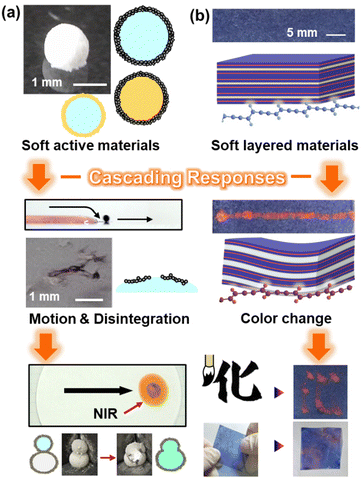 | ||
| Fig. 2 Cascading responses in this article. (a) Soft active material as a functional carrier (Section 2). Reproduced from ref. 23–25 with permission. Copyright 2017, 2009, 2022 American Chemical Society. (b) Soft layered material as a sensor (Section 3). Reproduced from ref. 26 with permission from the Royal Society of Chemistry. Reprinted with permission from ref. 27. Copyright 2023 American Chemical Society. | ||
2. Delivery and release of materials based on cascading responses
Soft active matter has attracted much interest for its applications in soft robotics, microfluidics, micromachines, and substance delivery.28 The induction and timing are significant factors for the motion of small objects, such as microparticles and droplets, as well as their direction and velocity control. In connection with the research on motion control, the controlled release of functional materials from small objects contributes to maintaining and improving the pharmacological benefits and minimizing the adverse effects in the fields of biomaterials, cosmetics, and agrochemicals.29 Section 2 introduces our challenges for controlling the motion of small objects (material delivery) and releasing substances from the object (material release) in a controlled manner with external stimuli based on cascading responses. Specifically, this feature article focuses on liquid marbles (LMs), which are millimeter-sized liquid droplets covered by hydrophobic solid particles in the gaseous phase,30–37 as carriers.38The cascading responses presented in this section are multiscale systems, and all spatial scales are intricately coupled, which determine the motion and stability of the LMs. At the molecular/nanometer scale, the interface chemistry determines hydrophilic–hydrophobic balance of the particulate LM stabilizer, which affects the wetting phenomena of the particulate LM stabilizers at a gas–liquid interface, and the intermolecular interaction impacts the phases of the particulate materials (solid or liquid). The adsorption/desorption of the particles to/from the gas–liquid interface and the melting of the particles are significant events at the submicrometer and micrometer scales. At and above the micrometer scale, changes in the chemistry and physics of the liquid and gas phases affect the properties of the liquid–gas interfaces and the LM stabilizers, resulting in motion of LMs and release of materials from LMs via their disintegration.
2.1. Material delivery based on cascading responses
The stimulus-driven motion of small objects is a fascinating topic in chemistry.28,39–42 Specific instances of material delivery using LMs based on cascading responses are described below. The key material in this system is hydrophobic solid particles, consisting of conjugated polymers,43,44 which can transduce near-infrared (NIR) light to heat. The LM stabilizers with hydrophobic surfaces can stabilize more stable LMs via adsorption at gas–liquid interface, compared with those with hydrophilic surfaces. (Hydrophilic particles tend to disperse into liquid phase, rather than to adsorb at gas–liquid interfaces.) The delivery of materials using LMs can be more easily realized using the stable LMs. The LMs covered by these hydrophobic conjugated particles exhibit photothermal properties and can move on a planar air–water interface with the irradiation of NIR light.45–52 The motion of the LMs realizes the delivery of the inner liquid of the LMs and particulate stabilizers. The mechanism of motion is explained as follows (Fig. 3): irradiation of NIR light (Stimulus 1) on the LM floating on a planar air–water interface (Material 1), targeting a three-phase air–water–LM contact line, and heat generation at the irradiated area in a site-selective manner (Response 1 = Stimulus 2). The heat generated on the LM is transferred to the planar air–water bulk interface, forming a surface temperature gradient around the LM (Response 2 = Stimulus 3). This temperature gradient creates a surface tension gradient on the bulk air–water interface, leading to the generation of a Marangoni flow (Response 3 = Stimulus 4) that propels the LM motion (Response 4). The LM slides on the air–water interface in the same direction as that of the NIR light irradiation (negative phototaxis). Notably, inexhaustible sunlight can also function as an environmentally friendly light source that promotes LM motion,45 facilitating the development of an ecologically sustainable delivery system. The range of accessible light sources should be increased if it is possible to adjust the wavelength at which light-to-heat transduction occurs through the design of the chemical structure of the materials which form particles, Intelligent delivery technologies will advance and allow for even more accurate motion control.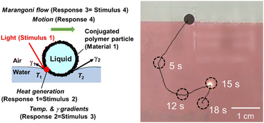 | ||
| Fig. 3 Motions of a liquid marble (LM) on a planar air–water interface driven by site-selective near infrared (NIR)-laser light irradiation. Reproduced from ref. 52 with permission. Copyright 2022 American Chemical Society. | ||
Using light-transmitting particles to cover the upper surfaces of the LM, a delivery system has been realized in which the LM moves both in the direction same and opposite to the light irradiation (negative and positive phototaxis) (Fig. 4).53
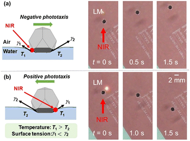 | ||
| Fig. 4 Negative (a) and positive (b) phototaxis of an LM on a planar air–water interface driven by site-selective NIR laser light irradiation. The LM is coated by one polymer plate with photothermal property and three polymer plates with highly transparent property at the bottom and the upper parts of the LM, respectively. Reproduced from ref. 53 with permission. Copyright 2021 American Chemical Society. | ||
Newton's equation of motion can be utilized to describe the motion of the LM at the air–water interface (eqn (1)).23
| m(d2x/dt2) = Δγw − ςv | (1) |
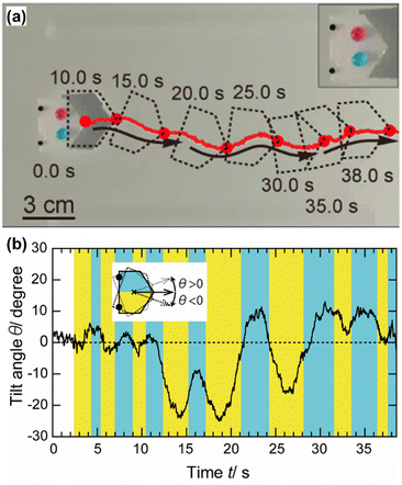 | ||
| Fig. 5 (a) Motions of a plastic boat driven by focused sunlight irradiation. Inset is a magnified image of the boat carrying two dyed water droplets on it. Non-linear motions can be realized using two LMs docked to the boat. (b) The relationship between the tilt angle of the boat and the time during the motions. Reproduced from ref. 45 with permission from Wiley. | ||
Notably, the LMs show amphibious motions.23 The LMs placed on the planar water film can move down the meniscus at the rim of the water film in a sliding manner to be transferred onto the solid substrate (Fig. 6). The motion from air–water interface (fluidic field) to air–solid interface (elastic field) could be realized by both light-induced Marangoni flow and air blow. The LM can move on a solid substrate in a rolling manner because of its near-spherical shape. Here the potential energy at the air–water interface is converted to kinetic energy for motion on the solid substrates. Interestingly, the LM on the solid substrate can return to the air–water interface of the water film with the aid of an airflow. The motion from air–solid interface to air–water interface could not be realized by light irradiation. This is because the Marangoni flow could not be generated on elastic air–solid interface.
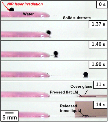 | ||
| Fig. 6 Transfer of an LM from the air–water interface (fluid field) to the air–solid interface (elastic field). The LM driven by NIR laser-induced Marangoni propulsion escaped the water meniscus and is transferred to the air–solid interface. Application of mechanical stress to the LM using a cover glass leads to disintegration of LM, followed by release of the inner liquid. Reproduced from ref. 23 with permission. Copyright 2017 American Chemical Society. | ||
The particulate stabilizers of LMs for material delivery are not limited to PPy. Other conjugated polymers, such as polyaniline,46 poly(3,4-ethylenedioxythiophene),47 poly(ethylpyrrole),49,52 poly(alkylaniline),50,51 and poly(3-hexylthiophene),48 can also be used. The performance and longevity of LMs in motion and material delivery task should depend on the photothermal property, size/shape and hydrophilicity–hydrophobicity balance of the LM stabilizer. One can choose LM stabilizer depending on the purpose and conditions. Non-aqueous liquids can also be applied as the internal liquids, including glycerol, tetrabromoethane and diiodomethane.51 The internal liquids are another important parameter which determines performance of LM motions. The LMs containing liquids with lower specific heat and thermal conductivity showed longer path length per one light irradiation shot and longer decay time. This is because heat generated at LM stabilizer adsorbed at droplet surface could be efficiently transferred to the water surface around the LM, rather than consumed to increase the temperature of internal liquid. The density of internal liquid also plays a role in motion of LMs. Gravity works strongly on the LM containing the inner liquid with higher density, resulting in pushing the LM placed on the water surface downward and bending the water surface largely. This caused increases of the contact area between the LM and the water surface. Thereby, the heat generated at LM stabilizer adsorbed on the LM surface could be transferred to the water surface more efficiently, which can generate a stronger Marangoni convection.51 The concept of the cascading response-based material delivery can be applied to the solid particle-stabilized emulsions56 and bubbles57,58 coated by conjugated polymer shells and conjugated polymer-coated solid objects.59 In these systems, oil, gaseous and solid materials encapsulated by the particle shell may be delivered.
To enhance the motion control accuracy, the smaller size of light irradiation area might be preferable: the laser with smaller light irradiation area should realize irradiation in more precise site-selective manner, thereby resulting in well-controlled motion directions. Accurate laser positioning on the small objects including LMs, emulsions and bubbles is somewhat difficult in a manual manner, which should cause fluctuation of direction and velocity of their motions. To address this point, development of robotic systems that can automate the light-induced motions based on image analysis is one of promising ways. Development of systems that can control the motions of small objects by multiple external stimuli (e.g. magnetic and electric fields and light) can be another direction to which the research will proceed. This system should be realized using organic–inorganic composite particles that possess the properties of both organic and inorganic components as a particulate stabilizer.
The challenge in scaling up the light-induced material delivery system is a significant barrier against their practical application for the moment. To address this challenge, several points should be considered. (1) Fabrication of large LMs/emulsions/bubbles with high stability against mechanical stress and light irradiation on both solid and liquid surfaces. (2) Development of particulate stabilizer with high light-to-heat transducing ability. (3) Development of light source with high output power.
2.2. Material release based on cascading responses
The release of the inner liquid of the LMs is induced by cascading responses. LMs that can disintegrate and release the inner liquid in response to on-demand external stimuli have been developed utilizing solid particles whose surfaces are stimulated externally to shift from hydrophobic to hydrophilic, as stabilizers.32 The material release is realized based on the mechanism shown below (Fig. 7). Once the stimulus (Stimulus 1), such as pH and temperature, is applied to the LM (Material 1), the particulate stabilizer adsorbed at the air–water interface becomes highly hydrophilic (Response 1 = Stimulus 2), leading to their desorption from the droplet surfaces (Response 2 = Stimulus 3). The desorption of particles from the interfaces results in the disintegration of the LM, followed by the release of the inner liquid materials (Response 3).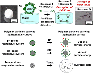 | ||
| Fig. 7 Stimulus-induced disintegration of an LM placed at a planar air–water interface. The LMs are stable in the long term on the planar air–water interface under conditions where the particle surfaces are hydrophobic enough for the particles to adsorb at air–water interface. Conversely, the application of stimulus induces LM disintegration and spontaneous dispersal of the particles into aqueous media because of hydrophilization of particle surface. Reproduced from ref. 24 with permission. Copyright 2009, American Chemical Society. | ||
LMs stabilized with solid particles carrying basic groups can be disrupted by the addition of acids. Specifically, polystyrene (PS) particles carrying a poly[2-(diethylamino)ethyl methacrylate] (PDEA) steric stabilizer (PDEA-PS particles) can serve as a pH-responsive LM stabilizer.24,60 PDEA has a pKa value of approximately 7 and exists in a hydrophobic and water-insoluble state under basic pH conditions. In contrast, PDEA is hydrophilic and water-soluble owing to protonation and exhibits positive charges under acidic pH conditions. These PDEA-PS particles exhibit pH-responsive behavior in the LM system, where the LMs disintegrate rapidly (20 s) after exposure to acid, followed by the release of their inner liquids, while remaining stable against exposure to base (>1 h). Upon protonation at molecular scale, the PDEA-PS particles exhibit a high degree of hydrophilicity, resulting in a decrease in the energy required for the particles to detach from the air–water interface at submicrometer and micrometer scales. This process causes the particles to desorb from the droplet surface and renders the LMs to disintegrate quickly above micrometer scale. The stability time should be varied depending on various parameters including humidity, temperature and volume of internal liquid of the LMs. High humidity should increase the stability time, because the evaporation of internal water could be suppressed. Low temperature should increase the stability time, because the surface tension of water increases, which leads to less wetting of water to the LM stabilizer. Small volume of internal liquid should increase the stability time on planar air–water interface, because the gravity effect decreases. A recent report demonstrated that LMs stabilized with silica particles carrying poly[2-(diisopropylamino)ethyl methacrylate] (PDPA) hairs disintegrate upon exposure to HCl gas due to hydrophilization of PDPA hairs via protonation.61 Similarly, the LM stabilized with pH-responsive poly(2-vinylpyrridine) particles62 and hydrophobically surface-modified chitosan particles63 are disrupted by addition of acid via particle-to-microgel/polyelectrolyte solution transition on protonation.
Base-induced disintegration systems are realized by expanding the concept of acid-induced disintegration. The use of acid group-carrying particles as LM stabilizers allows for the attainment of LMs with complementary characteristics that are destabilized by the addition of bases. Silica particles carrying poly[6-(acrylamido)hexanoic acid] (PAaH) hairs (PAaH–silica particles) on their surfaces work as pH-responsive LM stabilizers.64 On the planar air–water interface of bulk water with neutral or acidic pH, the LM stabilized with PAaH–silica particles can maintain long-term stability. Once the pH of the bulk water increases with the addition of an aqueous alkaline solution, the LM immediately disintegrates and the inner liquid is released. The addition of a basic aqueous solution renders the PAaH hairs on the silica particle surfaces deprotonated and hydrophilic, leading to the desorption of the silica particles from the air–water interface, followed by disintegration. LMs that can be disrupted by the addition of bases have also been prepared using succinic anhydride-esterified poly(2-hydroxypropyl methacrylate)65 and poly(styrene-co-acrylic acid-co-2,2,3,4,4,4-hexafluorobutyl methacrylate).66
As a temperature triggered system, we developed poly(N-isopropylacrylamide) (PNIPAAm) particle-stabilized LMs.67 PNIPAAm are temperature-responsive polymers, exhibiting lower critical solution temperature (LCST) in aqueous solutions. Below the LCST (approximately 32 °C), water molecules and pendant amide groups of PNIPAAm form hydrogen bonds, making PNIPAAm hydrophilic and water-soluble. In contrast, PNIPAAm precipitates in the aqueous phase above the LCST because of the destruction of hydrogen bonds. This temperature-dependent behavior suggests that PNIPAAm exhibits hydrophilic and hydrophobic characteristics below and above the LCST, respectively. The LMs are fabricated at room temperature using an aqueous salt solution (Na2SO4) as the inner liquid and PNIPAAm particles as the stabilizers. Here, the salt was added to decrease the LCST of PNIPAAm, which is hydrophobic at room temperature. The LMs are stable for more than 24 h at room temperature on the planar air–water interface of the bulk water containing salt. Once the temperature of the bulk aqueous solution decreases, the LMs disintegrate because of an increase in the wettability of the PNIPAAm particles. The concept of cascading response-based material release can also be applied to solid particle-stabilized emulsion droplet68–71 and bubble57,58,72–79 systems.
The disintegration of the LMs can also be realized by the application of external stimuli, inducing a phase change of the LM stabilizer from solid to liquid. In this system, phase-change materials (PCMs), which show a solid-to-liquid phase transition upon increasing the temperature,80 are used as a base material for the LM stabilizer. Natural fatty acids (FAs) are the most widely studied PCMs. The melting points of the FAs depend on their alkyl chain length at molecular scale and vary in the range of 20–80 °C.81 Our group developed LMs that can be disrupted by light irradiation utilizing the FA core/PPy shell composite particles (FA/PPy particles) as an LM stabilizer (Fig. 8).25,82 The disintegration and release of the inner liquid of the LMs can be realized in a cascade manner. By hybridizing PPy as a photothermal converter (Material 1) and the FAs as a PCM (Material 2), NIR light (Stimulus 1) can be converted to heat (Response 1 = Stimulus 2) because of the photothermal properties of PPy, leading to a solid-to-liquid phase change of the FA core (Response 2 = Stimulus 3) at the submicrometer and micrometer scales. The contact of the inner liquid with the supporting substrate via penetration through the liquefied thin FAs film resulted in the disintegration of the LMs at and above micrometer scale, followed by release of the inner liquid (Response 3).
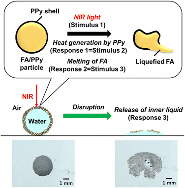 | ||
| Fig. 8 Disintegration of LM stabilized with fatty acids (FAs) particles coated by PPy overlayer induced by NIR laser light irradiation. Reproduced from ref. 25 with permission. Copyright 2022, American Chemical Society. | ||
There is a close correlation between the melting point of the FAs and the light irradiation time required for LM disruption (disintegration time). Light power is another that can control the disintegration time. The tuning of these parameters makes it possible to control the disintegration time between instantaneous and approximately 10 s; the disintegration time decreases with the decreasing melting point of the FA component and increasing light power. Note that the LMs could be stable without any detectable shrinkage and disintegration for >10 min at 25 °C under no light irradiation. Notably, natural sunlight can lead to the LMs becoming disrupted.
The disintegration of LMs induced by external stimuli serves as a visual cue for the environmental changes surrounding the LMs. The liquid materials released from the LMs can be used as environmental monitoring indicators, which could potentially lead to the development of sensing technologies (Fig. 9). Furthermore, the disintegration of the LMs leads to the development of a microreactor. The coalescence of two LMs in contact with each other by NIR light irradiation can trigger a chemical reaction (Fig. 10). The NIR light irradiation of the contact area of the LMs leads to the melting of the FA component of the FA/PPy particles via heat generation due to the PPy shell and weakens the particle shell protection. Once the inner liquids of the LMs are in contact with each other (Response 3 = Stimulus 4), the coalescence of the LMs immediately starts chemical reaction by mixing the two inner liquids (Response 4).
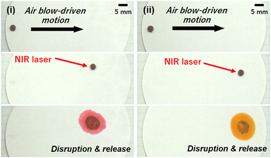 | ||
| Fig. 9 Motions of LM stabilized with FA particles covered by PPy overlayer on the filter paper by air blowing. Disintegration of the LM induced by the NIR-laser light irradiation, followed by release of inner liquid (aqueous solution of methyl orange) on (i) filter paper containing citric acid and (ii) pristine filter paper. Reproduced from ref. 25 with permission. Copyright 2022, American Chemical Society. | ||
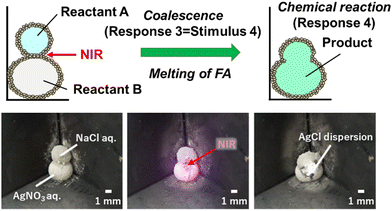 | ||
| Fig. 10 NIR laser light-induced coalescence of two LMs containing NaCl and AgNO3 aqueous solutions, respectively. Precipitation reaction of AgCl is induced by mixing two inner liquids. The LMs are stabilized with FA particles coated by PPy overlayer. Reproduced from ref. 25 with permission. Copyright 2022, American Chemical Society. | ||
3. Sensors based on cascading responses
Section 3 shows the sensing devices that combine multiple stimuli-responsive materials based on the concept of cascading responses. Our group has focused on the stimuli-responsive color-change properties of polydiacetylene (PDA) to develop sensing materials and devices. In general, PDA exhibits color-change properties in response to applied stresses (Fig. 11).83–96 External stimuli induce torsion of the PDA main chain leading to color changes through molecular motion (Fig. 11a). The responsivity to stimuli is controlled by the design and synthesis of diacetylene (DA) monomers in previous works.97,98 Our group controlled the responsivity by the intercalation of cationic guests in the layered structure of DA, such as 10,12-pentacosadiynoic acid (PCDA) (Fig. 11b).99–107 As the structural flexibility is tuned by the type of intercalated guest, the color-changing behavior is controlled by changes in the flexibility (mobility) of the layered structure. However, the responsiveness to chemical, thermal, and frictional stresses has mainly been studied; color changes in the PDA derivatives were not observed under other stresses such as light and compression stresses. Sufficient motion at the molecular level is not induced by other stresses at the macroscopic scale. Therefore, the color change of PDA is observed to only be caused by stresses of the specific types and within ranges. Our group applied the concept of cascading responses to expand the types and ranges of detectable stresses. Section 3 presents a new photo- and mechano-responsiveness using a layered PDA. The PDA-based sensing devices can visualize and quantify the applied stresses. In these sensing systems, the red-color intensity is used as a metric for the quantification. An increment of red color intensity (Δx = x − x0) is estimated from the photographs taken under the same conditions, where x is the observed red-color intensity and x0 is the original x before the application of the stress. The standard curve about the relationship between the applied stress and Δx is prepared using more than three samples to ensure the reproducibility.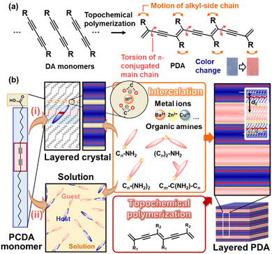 | ||
| Fig. 11 Schematic illustration of the layered PDA. (a) DA monomer, its topochemical polymerization, and molecular motions with the application of external stimuli. Reprinted from ref. 92 with permission from the Royal Society of Chemistry. (b) Intercalation route (i) and self-organization route (ii) for preparation of the layered composites based on PDA with topochemical polymerization. Reprinted from ref. 102 with permission from Elsevier and Wiley-VCH, respectively. | ||
3.1. Photoresponsive sensors based on cascading response
The layered PDA derived from PCDA, an amphiphilic monomer, does not respond to light stimulus. In previous studies, the designed DA monomer containing photo-functional moieties, such as the azobenzene moiety, showed responsiveness.108–110 These approaches provide light responsiveness to PDA at the molecular level. Our group achieved responsiveness to near-infrared (NIR) and microwaves based on the cascading response (Fig. 12 and 13).111,112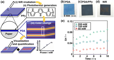 | ||
| Fig. 12 Visualization and quantitative detection of NIR using PPy/PDA-coated paper device. (a) Structure of the device consisting of layered PDA with PPy coating and its NIR visualization mechanisms with the irradiation (i), photothermal generation (ii), and color change (iii). (b)–(d) Photographs of PDA-coated paper (b), after the PPy coating (c), and after writing the characters with irradiation using a NIR laser pointer (808 nm) (d). (e) Time-dependent changes of the Δx value with irradiation of 50 mW (red circle), 100 mW (blue square), and 200 mW (green triangle) NIR light. Reproduced from ref. 111 with permission from the Royal Society of Chemistry. | ||
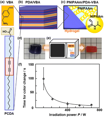 | ||
| Fig. 13 Synthesis, structure, and application of PNIPAAm/PDA-VBA thermo-responsive color-change gel. (a) Layered composite of PCDA and VBA. (b) Grafting and polymerization of NIPAAm to the interlayer VBA in the PCDA–VBA. (c) Polymerization of PNIPAAm and topochemical polymerization of PCDA. (d) and (e) PNIPAAm/PCDA–VBA gel and its after the color change (e). (f) Relationship between the P and tf. Reproduced with permission from ref. 112. Copyright 2020 American Chemical Society. | ||
A thin layer of conjugated polymer is coated on the layered PDA (Fig. 12a–c).111 As mentioned in Section 2, conjugated macromolecules, such as conductive polymers and graphitic carbons, have photothermal conversion properties. For example, PPy generates heat upon irradiation with NIR light.43,44 If PPy (Material 1) is combined with layered PDA (Material 2), the NIR light (Stimulus 1) can be converted into thermal stress (Response 1 = Stimulus 2). The layered PDA exhibits the color change (Response 2) upon heating. In our previous work, a PPy thin-layer coating was achieved by supplying monomers from the vapor phase.113,114 The layered PDA is coated on a filter paper (Fig. 12b). The original blue color of PDA changes to blue-black after PPy coating (Fig. 12c). When NIR light (λ = 808 nm) is irradiated to the PPy/PDA paper, the color change to red is observed with increasing irradiation time (Fig. 12d). When the power of the irradiated NIR light increased, a higher temperature is achieved by irradiation. Layered PDA with intercalated zinc ion (Zn2+) is used to control the responsivity in the higher temperature range. PDA–Zn2+ shows responsiveness to irradiation power (Fig. 12e). In this manner, the visualization and quantification of NIR are achieved using PPy/PDA or PPy/PDA–Zn2+ based on the cascading response.
Another example of a light-responsive color change is the imaging and measurement of invisible microwaves (Fig. 13).112 Layered PDA is used as a cross linker of PNIPAAm as a typical thermoresponsive hydrogel (Fig. 13a–c). Layered PCDA intercalated with 4-vinylbenzylamine (VBA) acts as a crosslinker for the hydrogel. When PDA is dispersed in PNIPAAm with a typical organic crosslinker, N,N′-methylenebisacrylamide (MBAAm), the PNIPAAm/PDA/MBAAm hydrogel is easily broken upon stretching. In contrast, the PNIPAAm hydrogel crosslinked with PDA-VBA is durable during stretching (Fig. 13d). If the thermoresponsive hydrogel (Material 1) is combined with layered PDA (Material 2), microwave irradiation can induce heat generation and volume changes (Response 1 = Stimulus 2). Color change (Response 2) is achieved by thermal and mechanical stresses. The PNIPAAm/PDA-VBA hydrogel exhibits gradual color change with increasing temperature. As the changes in the red-color intensity and sample volume are correlated, the color changes are coupled with the temperature-responsive volume shrinkage of the PNIPAAm gel. The motion of the PNIPAAm chains initiate that of the layered PDA, leading to a color change. The PNIPAAm/PDA-VBA hydrogel exhibits a color change upon microwave irradiation (Fig. 13e). The red-color intensity increases with increasing irradiation time and microwave power (Fig. 13f). Visualization and quantification of microwave are achieved using the PNIPAAm/PDA-VBA hydrogel. In this manner, based on cascading responses, the layered PDA can exhibit color changes in response to stresses that are not directly detected by the layered PDA through the conversion of the original stimuli.
3.2. Mechanoresponsive sensors based on cascading responses
Classical force sensors have been prepared using strain gauges and piezoelectric materials. In recent decades, mechanoresponsive materials based on chromophores have been studied in the fields of chemistry and materials science.115–131 In these studies, microscopic molecules and materials were designed to achieve responsiveness to macroscopic mechanical stresses, such as shear, compression, and tensile stresses. The fluorescent and visible colors change with the changes in the assembled states of the chromophores. If the flexibility of macromolecules containing chromophores is enhanced by molecular design, mechanical stresses can induce color changes through molecular motion. Another typical strategy is to embed chromophores in stretchable polymer matrices, such as polyurethane (PU) (Fig. 14). The latter can be regarded as a cascading response. Macroscopic force (Stimulus 1) is transferred via the matrix polymer (Material 2) to molecular motion (Response 1 = Stimulus 2). The coupled motion of the chromophore (Material 2) eventually induces a color change (Response 2). Our group also designed and synthesized this type of mechanoresponsive material based on layered PDA (Fig. 14).27 The layered PDA is dispersed in a PU matrix (Fig. 14a). A block copolymer, namely poly(ethylene glycol) (PEG)-block-polyethyleneimine (PEI) (PEG–PEI), is used as the interlayer guest linking the interlayer space and outerlayer PU matrix. The PEI segment is intercalated into the layered PDA, and the PEG segment is entangled with the soft segment of PU. When macroscopic mechanical stresses, such as tensile, compression, and frictional stresses, are applied to PU, the motion of the layered PDA is induced via PEG–PEI entangled with PU. Therefore, a blue-to-red color change is observed under the applied tensile, compression, and frictional stresses (Fig. 14b). Moreover, the accumulated stresses are visualized and quantified by Δx using PU/PDA-(PEG–PEI) (Fig. 14c). Therefore, the distribution of the accumulated stresses is visualized by Δx.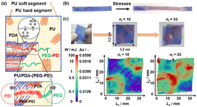 | ||
| Fig. 14 Layered PDA with the intercalation of PEG–PEI embedded in PU matrix. (a) Schematic illustration of PU/PDA-(PEG–PEI) (upper) and its magnified image of the intercalated PEG–PEI with the interlayer interaction with the layered PDA (red) and outerlayer interaction with PU (green). (b) Photographs of the film before and after stretching. (c) Photographs (upper) and 2D mapping image (lower) of the PU/PDA-(PEG–PEI) film with stretching in the diagonal line at nt = 10 and 35. Reproduced with permission from ref. 27. Copyright 2023 American Chemical Society. | ||
In our previous works, friction forces are visualized and quantified using layered PDA coated on a paper substrate.102,132,133 The responsivity, which is the detection range of the strength, is controlled by the intercalated guests. For example, improved sensitivity, i.e. the detection of a weaker friction force, can be achieved by the intercalation of PEI. The macromolecular guest enhances the flexibility of the layered structure compared to low-molecular-weight guests. As the low-molecular-weight guests are self-assembled in the interlayer space, the structural flexibility is lowered by the densely packed layered structure with the higher crystallinity. In contrast, the polymeric guests are loosely accommodated in the interlayer space. The mobile polymer guests provide the more flexible layered structure. The layered PDA and PDA–PEI visualize and quantify the friction forces in the ranges of 7.6–23 and 0.2–6.4 N as observed in the writing and toothbrushing motions, respectively (Fig. 15a).132,133 However, the detection of the weaker friction forces is not achieved using the layered PDA. Moreover, other stresses, such as tensile and compressive stresses, in any strength range cannot be detected using PDA alone. This implies that the molecular motion of the layered structure that leads to color changes is not induced by weaker friction or other stresses. If a more dynamic movable structure is designed to achieve high sensitivity, the torsion of the PDA main chain yielding the color change can be caused by thermal stresses under ambient conditions. Therefore, specific designs of materials and devices are required to achieve high sensitivity. In particular, responsivity to weak compression stresses has not been reported, except in one 2022 report (Fig. 15b).134
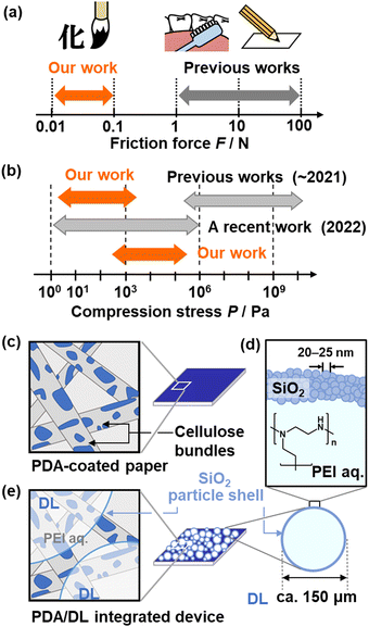 | ||
| Fig. 15 Cascading responses for mechanoresponsiveness. (a) and (b) Detection range of friction forces (a) and compression stresses (b) in the previous and our works. (c) PDA-coated paper. (d) DL consisting of PEI aq. and SiO2 nanoparticles as the core and shell, respectively. (e) DL/PDA integrated device. Reprinted from ref. 135 with permission from Wiley-VCH. | ||
The cascading response is introduced by combining dry liquid (DL) as a stimuli-responsive capsule material and layered PDA (Fig. 15c–e). A DL, a liquid droplet stabilized by solid particles, is a promising liquid material for storage and carriers.136,137 In our study, the interior liquid is an aqueous solution containing PEI. The shell part comprises silica nanoparticles with a surface modification by polydimethylsiloxane (PDMS) (Fig. 15d). As the fragile droplet shows mechanoresponsiveness, a scheme of cascading responses can be designed by combining it with layered PDA (Fig. 15e).26,135,138,139 When mechanical stresses (Stimuli 1) are applied to the DL (Material 1), the disruption induces the outflow of the interior liquid as a chemical stress (Response 1 = Stimuli 2). The PEI in the interior liquid is intercalated into layered PDA (Material 2). Torsion of the conjugated main chain induces a color change (Response 2). The DL is disrupted by multiple weak mechanical stresses, such as compression and friction. Therefore, the cascading response enables responsiveness to the type and strength of mechanical stresses that are not directly detected by the layered PDA. In particular, responsiveness to compressive stresses has not been reported for PDA in previous works. The device is prepared by just dispersion of DL on the layered PDA coated on a paper substrate (Fig. 15e).135 The weak friction and compression stresses are visualized and quantified by the device integrating PDA and DL (Fig. 16 and 17).26,138 The weaker friction stresses in the range of 0.006–0.08 N are also detected by DL/PDA (Fig. 16a–c). This range is weaker than that of the tooth-brushing motion (Fig. 15a). The device visualizes the pressure distribution in calligraphic writing (Fig. 16d–f). The pressure distribution is clearly different for the expert experience, and beginner.
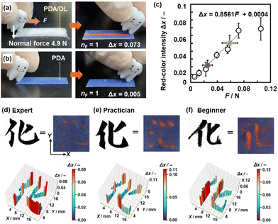 | ||
| Fig. 16 PDA/DL device in response to weak friction force. (a) and (b) Photographs of PDA/DL (h) and PDA (i) before (left) and after (right) the application of weak friction force. (j) Photographs and their Δx with the application of weak friction forces. (c) Relationship between F and Δx as the standard curve (open circles) and estimation of simulated unknown F (green and purple circles). (d)–(f) Photographs (upper) and force distribution mapping (lower) of the handwritten character on a paper using ink (left) and on the PDA/DL device without ink (right) by the expert (d), practician (e), and beginner (f). Reproduced from ref. 26 with permission from the Royal Society of Chemistry. | ||
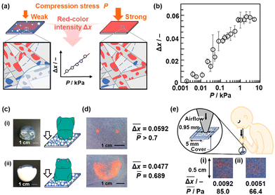 | ||
Fig. 17 PDA/DL paper device for compression-stress imaging. (a) PDA/DL-integrated device on a paper exhibiting the color changes depending on the strength of the applied compression stresses. (b) Relationship between P and Δx. (c) Two different settings (the setups (i) and (ii)) to apply the different compression stresses. (d) Photographs of the PDA/DL paper after the application of the compression stress by the setups (i) and (ii) and their measured  and estimated and estimated ![[P with combining macron]](https://www.rsc.org/images/entities/i_char_0050_0304.gif) values. (e) Color-change properties and values. (e) Color-change properties and  values with the application of compression stresses originating from strong (i) and weak (ii) expiratory pressure. Reproduced from ref. 135 with permission from Wiley-VCH. values with the application of compression stresses originating from strong (i) and weak (ii) expiratory pressure. Reproduced from ref. 135 with permission from Wiley-VCH. | ||
The PDA/DL paper-based device shows color changes in response to the compression stresses (P/kPa) in the range of 3.9 Pa–4.9 kPa that have not been achieved in the earlier works (Fig. 17).135 The applied P is colorimetrically measured by Δx using the relationship in the standard curve (Fig. 17a and b). Moreover, the applied P is visualized by the red-color intensity (Fig. 17c and d). A weak compression stress originating from expiration is imaged and colorimetrically measured using this device (Fig. 17e). Moreover, the spatial distribution of the compressive stresses is visualized by coating the layered PDA inside the melamine sponge (Fig. 18). After the dispersion of DL on the top face, the compression stress is applied to the sponge containing the layered PDA (Fig. 18a–c).138 The compression stress in the range of 3.50–675 kPa is detected using the sponge device. This range is higher than that of paper-based devices owing to the elasticity of the sponge. A cascading response is achieved in the sponge device. The cross-section of the device shows a red color distribution depending on the locally applied compression stress. In other words, the compression-stress distribution is visualized by color. For example, compression stress is applied to the sponge device using the plastic ornament of a giant panda with its feet in different contact states (Fig. 18d). The different stress distributions are visualized and quantified by the red-color distribution on the cross section (Fig. 18e and f). The DL/PDA device is used to visualize the distribution of the compression stresses originating from the circular stapler for anastomosis of the intestinal tract, which is a surgical device (Fig. 18g–k).
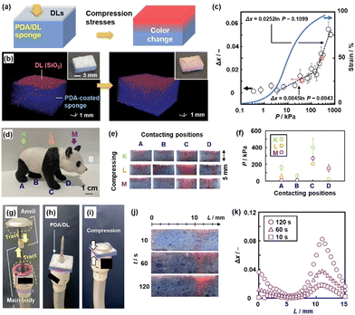 | ||
| Fig. 18 PDA/DL sponge device for compression-stress imaging. (a) and (b) Schematic illustrations (a) and X-ray computerized tomography stereoscopic images and photographs (inset) (b) of the PDA/DL sponge device before (left) and after (right) the application of compression stress. (c) Relationship between P and Δx (black circles, left axis) with the colorimetric estimation of unknown compression stresses (red triangles) and stress–strain curve of the sponge device (blue, right axis). (d) Photograph of a plastic ornament of giant panda. (e) and (f) Photographs of the sponge devices (e) and colorimetrically estimated P (f) on the parts A–D with the compression in the direction K–M in the panel (d). (j) Cross-sectional photographs with the compression for t = 10 and 120 s. (k) Relationship between L and average Δx representing the stress distribution of the purple type for t = 10, 60, and 120 s. Reproduced from ref. 138 with permission from Wiley-VCH. | ||
The cascading response using the sponge enables spatiotemporal imaging of the compression stress (Fig. 19).139 The red-color intensity increases with increasing application time of the compression stresses (Fig. 19b and c). This means that the applied impact, i.e. the product of force (F/N) and time (t/s), can be visualized and quantified using the device. When the nickel ion (Ni2+) is intercalated in the interlayer space of the layered PDA, the elapsed time after the application of the compression stress (τ/min) is visualized using the same device (Fig. 19d and e). Intercalation of PEI flowing out of the disrupted DL is delayed in the presence of Ni2+ in the interlayer space. The delayed color change enables the imaging of τ.
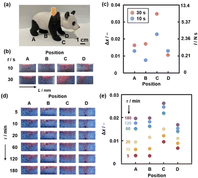 | ||
| Fig. 19 PDA/DL sponge device for spatiotemporal compression-stress imaging. (a) A plastic ornament of giant panda with four feet A–D contacting on the ground in the different states. (b) Cross-sectional photographs of the sponge devices set under the feet A–D for t = 10 and 30 s. (c) Relationship between the positions, Δx (left axis) and estimated maximum possible I (right axis). (d) Cross-sectional photographs of the PDA-Ni2+/DL sponge devices after the elapsed time (τ =) 5–180 min of the compression stress. (e) Relationship between the positions A–D and Δx. Reprinted from ref. 139 with permission from Wiley-VCH. | ||
In our previous works, we have mainly used a commercial DA monomer, PCDA, to develop sensing materials. Based on the insights, the newly designed DA molecules expand the potentials of development of advanced sensing materials. The more versatile combinations of stimuli-responsive materials can be designed for further development of cascading responses. In the applications, visualization of invisible forces is an important challenge in various fields, such as robotics, medicine, arts, and sports. Advanced PDA-based sensors contribute to visualization and quantification of forces with various types, ranges, and scales.
4. Summary and outlook
This article presents cascading responses as a concept for designing new dynamic functional systems based on the integration of stimuli-responsive materials. In cascading responses, an input Stimulus 1 is converted into output response N through repetitive responses in a system. The combination of stimuli-responsive materials (Materials 1, 2, …, N) facilitates the conversion and/or enhancement of the stimuli (Stimulus 1, 2, …, N) to induce response N. Therefore, a cascading response enables the responsiveness of different types and ranges that are not detectable using solely a single stimulus-responsive material. Section 2 introduces the stimuli-responsive functional carriers for the delivery and release materials using LM engineering. Various triggers can be integrated into carriers to induce cascading responses. Section 3 describes the tunable stimuli-responsive color-changing materials based on layered conjugated polymers for light and force sensing. The integration of the other stimuli-responsive materials enables the detection of external stimuli that cannot not be detected using only the layered PDA. In this manner, cascading responses expand the potential of stimulus responsiveness, including the types and ranges. The cascading responses systems described in this review article enable the conversion of a weak stimulus into a strong response that can be macroscopically detected by the naked eye. However, multiple conversions may sometimes cause decay of the stimulus. In such cases, a minimum number of conversion steps is preferred when designing the system. As cascading responses are prepared by integration of stimuli-responsive materials, finding the appropriate combinations is significant for the device design. In addition, specific preparation methods of the composite materials and integrated devices are required to achieve the designed cascading responses. Tuning the output response as the subsequent input stimulus is also needed to induce cascading response.Cascading responses have been applied for the further development of functional carriers and sensors. Research on functional carriers could move toward autonomous motion and many-body systems, where carriers and other objects in the field of motion interact in both attractive and repulsive manners. To realize such systems and gain insight into the underlying cascading response mechanisms, the crucial challenges are the precise design and synthesis of particulate materials to fabricate functional carriers and the chemical and physical evaluation of the kinetic field of the carrier. Mechanoresponsive materials based on cascading responses are applied to analyze, understand, and reproduce motions. Such data are used to transmit the professional motions of artists, craftspeople, and physicians to the next generation. The cascading response is helpful for tuning the responsivity, such as the type, strength, and length of the applied stimuli. Chemists can design and synthesize stimulus-responsive molecules and materials. Their refined integration realizes tailored cascading responses, as observed in living organisms. In addition to development of unit materials, their integration into a system is an important challenge for cascading response applications. New dynamic functional materials, such as carriers, sensors, actuators, and reparative agents, with designed responsiveness and responsivity can be developed by integrating stimulus-responsive materials. Furthermore, the integration of cascading responsive systems, such as delivery, release, and sensing, contributes to the development of microbots and soft robots, and the understanding of animal signalling and locomotion mechanisms.
Data availability
No primary research results, software or code have been included and no new data were generated or analyzed as part of this Feature Article.Conflicts of interest
There are no conflicts to declare.Acknowledgements
The authors thank all the collaborators contributing to the related works in this article. This work was partially supported by Grant-in-Aid for Scientific Research (KAKENHI: JP16H04207, JP20H02803 and JP24K01562 for SF, 22685022 and JP22H02148 for YO, and JP23106720 (Molecular Soft-Interface Science) for SF), JST PRESTO (YO., JPMJPR16N2), Asahi Glass Foundation (YO), AMED (YO, JP21lm0203012j0003, JP23ym01268113j0002), and Nakatani Foundation (Biomedical Engineering Research, YO).Notes and references
- M. A. C. Stuart, W. T. S. Huck, J. Genzer, M. Müller, C. Ober, M. Stamm, G. B. Sukhorukov, I. Szleifer, V. V. Tsukruk, M. Urban, F. Winnik, S. Zauscher, I. Luzinov and S. Minko, Nat. Mater., 2010, 9, 101 CrossRef PubMed.
- P. Theato, B. S. Sumerlin, R. K. O’Reilly and T. H. Epps, III, Chem. Soc. Rev., 2013, 42, 7055 RSC.
- Q. Zhang, J. Zhang, S. Wan, W. Wang and L. Fu, Adv. Funct. Mater., 2018, 28, 1802500 CrossRef.
- M. I. Khazi, W. Jeong and J. M. Kim, Adv. Mater., 2018, 30, 1705310 CrossRef PubMed.
- S. J. Rowan and C. Weder, Israel J. Chem., 2020, 60, 100 CrossRef CAS.
- J. Uchia, B. Soberats, M. Gupta and T. Kato, Adv. Mater., 2022, 34, 2109063 CrossRef PubMed.
- S. Ding, G. Shi and A. Zhu, Chem. Commun., 2022, 58, 13171 RSC.
- Y. Hiruta, Polym. J., 2022, 54, 1419 CrossRef CAS.
- S. Ding, G. Shi and A. Zhu, Chem. Commun., 2022, 58, 13171 RSC.
- X. Wu and C. Barner-Kowollik, Chem. Sci., 2023, 14, 12815 RSC.
- M. Nakayama, Polym. J., 2023, 56, 71 CrossRef.
- S. Wang and M. W. Urban, Chem, 2023, 9, 1362 CAS.
- S. Uredat, A. Gujare, J. Runge, D. Truzzolillo, J. Oberdissue and T. Hellweg, Phys. Chem. Chem. Phys., 2024, 26, 2732 RSC.
- K. Tanaka and Y. Chujo, Polym. J., 2023, 55, 353 CrossRef CAS.
- K. Ariga, J. Song and K. Kawakami, Chem. Commun., 2024, 60, 2152 RSC.
- H. Kitano, Science, 2002, 295, 1662 CAS.
- K. C. Nicolaou, D. J. Edmonds and P. G. Bulger, Angew. Chem., Int. Ed., 2006, 45, 7134 CAS.
- C. Grondal, M. Jeanty and D. Enders, Nat. Chem., 2010, 2, 167 CrossRef CAS PubMed.
- S. R. White, N. R. Sottos, P. H. Geubelle, J. S. Moore, M. R. Kessler, S. R. Sriram, E. N. Brown and S. Viswanathan, Nature, 2001, 409, 794 CrossRef CAS PubMed.
- F. Pierini, P. Nakielski, O. Urbanek, S. Pawłowska, M. Lanzi, L. D. Sio and T. A. Kowalewski, Biomacromolecules, 2018, 19, 4147 CrossRef CAS PubMed.
- C. Adamson and M. Kanai, Org. Biomol. Chem., 2021, 19, 37 RSC.
- K. Ariga and R. Fakhrullin, Bull. Chem. Soc. Jpn., 2022, 95, 774 CrossRef CAS.
- H. Kawashima, M. Paven, H. Mayama, H. J. Butt, Y. Nakamura and S. Fujii, ACS Appl. Mater. Interfaces, 2017, 9, 33351 CrossRef CAS PubMed.
- D. Dupin, S. P. Armes and S. Fujii, J. Am. Chem. Soc., 2009, 131, 5386 CrossRef CAS PubMed.
- Y. Tsumura, K. Oyama, A.-L. Fameau, M. Seike, A. Ohtaka, T. Hirai, Y. Nakamura and S. Fujii, ACS Appl. Mater. Interfaces, 2022, 14, 41618 CAS.
- N. Shioda, R. Kobayashi, S. Katsura, H. Imai, S. Fujii and Y. Oaki, Mater. Horiz., 2023, 10, 2237 RSC.
- Y. Mochizuki, H. Imai and Y. Oaki, ACS Appl. Mater. Interfaces, 2023, 15, 48725 CrossRef CAS PubMed.
- H. Wang and M. Pumera, Chem. Rev., 2015, 115, 8704 CrossRef CAS PubMed.
- M. Bruneau, S. Bennici, J. Brendle, P. Dutournie, L. Limousy and S. Pluchon, J. Controlled Release, 2019, 294, 355 CrossRef CAS PubMed.
- P. Aussillous and D. Quéré, Proc.: Math., Phys. Eng. Sci., 2006, 462, 973 CAS.
- G. McHale and M. I. Newton, Soft Matter, 2015, 11, 2530 RSC.
- S. Fujii, S. Yusa and Y. Nakamura, Adv. Funct. Mater., 2016, 26, 7206 CrossRef CAS.
- E. Bormashenko, Langmuir, 2017, 33, 663 CrossRef CAS PubMed.
- P. M. Ireland, C. A. Thomas, B. T. Lobel, G. B. Webber, S. Fujii and E. J. Wanless, Front. Chem., 2018, 6, 280 CrossRef PubMed.
- X. Li, Adv. Colloid Interface Sci., 2019, 271, 101988 CrossRef CAS PubMed.
- B. T. Lobel, C. A. Thomas, P. M. Ireland, E. J. Wanless and G. B. Webber, Adv. Powder Technol., 2021, 32, 1823 CrossRef.
- Y. Zhang, H. Cui, B. P. Binks and H. C. Shum, Langmuir, 2022, 38, 9721 CAS.
- S. Fujii, Langmuir, 2022, 38, 12757 CrossRef CAS PubMed.
- D. Okawa, S. J. Pastine, A. Zettl and J. M. J. Fréchet, J. Am. Chem. Soc., 2009, 131, 5396 CrossRef CAS PubMed.
- J. Wang, ACS Nano, 2009, 3, 4 CrossRef CAS PubMed.
- T. Mirkovic, N. S. Zacharia, G. D. Scholes and G. A. Ozin, ACS Nano, 2010, 4, 1782 CrossRef CAS PubMed.
- S. Sánchez, L. Soler and J. Katuri, Angew. Chem., Int. Ed., 2015, 54, 1414 CrossRef PubMed.
- F. Li, M. A. Winnik, A. Matvienko and A. Mandelis, J. Mater. Chem., 2007, 17, 4309 RSC.
- K. M. Au, M. Chen, S. P. Armes and N. Zheng, Chem. Commun., 2013, 49, 10525 RSC.
- M. Paven, H. Mayama, T. Sekido, H.-J. Butt, Y. Nakamura and S. Fujii, Adv. Funct. Mater., 2016, 26, 3199 CrossRef CAS.
- H. Kawashima, R. Okatani, H. Mayama, Y. Nakamura and S. Fujii, Polymer, 2018, 148, 217 CrossRef CAS.
- N. Shimogama, M. Uda, K. Oyama, H. Hanochi, T. Hirai, Y. Nakamura and S. Fujii, Polym. J., 2019, 51, 761 CrossRef CAS.
- H. Inoue, T. Hirai, H. Hanochi, K. Oyama, H. Mayama, Y. Nakamura and S. Fujii, Macromolecules, 2019, 52, 708 CrossRef CAS.
- M. Šišáková, Y. Asaumi, M. Uda, M. Seike, K. Oyama, S. Higashimoto, T. Hirai, Y. Nakamura and S. Fujii, Polym. J., 2020, 52, 589 CrossRef.
- M. Uda, S. Higashimoto, T. Hirai, Y. Nakamura and S. Fujii, Polymer, 2021, 212, 123295 CrossRef CAS.
- M. Uda, H. Kawashima, H. Mayama, T. Hirai, Y. Nakamura and S. Fujii, Langmuir, 2021, 37, 4172 CrossRef CAS PubMed.
- M. Seike, M. Uda, T. Suzuki, H. Minami, S. Higashimoto, T. Hirai, Y. Nakamura and S. Fujii, ACS Omega, 2022, 7, 13010 CrossRef CAS PubMed.
- M. Uda, J. Fujiwara, M. Seike, S. Segami, S. Higashimoto, T. Hirai, Y. Nakamura and S. Fujii, Langmuir, 2021, 37, 11093 CrossRef CAS PubMed.
- H. Kawashima, H. Mayama, Y. Nakamura and S. Fujii, Polym. Chem., 2017, 8, 2609 RSC.
- T. Osumi, M. Seike, K. Oyama, S. Higashimoto, T. Hirai, Y. Nakamura and S. Fujii, J. Appl. Polym. Sci., 2021, 138, 51009 CrossRef CAS.
- D. Liu, M. Uda, M. Seike, S. Fukui, T. Hirai, Y. Nakamura and S. Fujii, Colloid Polym. Sci., 2022, 300, 255 CrossRef CAS.
- M. Ito, H. Mayama, Y. Asaumi, Y. Nakamura and S. Fujii, Langmuir, 2020, 36, 7021 CrossRef CAS PubMed.
- J. Yamada, M. Uda, S. Fukui, T. Hirai, Y. Nakamura and S. Fujii, Eur. Polym. J., 2020, 132, 109723 CrossRef CAS.
- H. Kawashima, A. Shioi, R. J. Archer, S. J. Ebbens, Y. Nakamura and S. Fujii, RSC Adv., 2019, 9, 8333 RSC.
- S. Fujii, M. Suzaki, S. P. Armes, D. Dupin, S. Hamasaki, K. Aono and Y. Nakamura, Langmuir, 2011, 27, 8067 CAS.
- E. Onodera, S. Usuda, H. Hara, M. Harun-Or-Rashid, S. Fujii, Y. Nakamura and S.-I. Yusa, Langmuir, 2024, 40, 11757 CrossRef CAS PubMed.
- S. Fujii, S. Kameyama, S. P. Armes, D. Dupin, M. Suzaki and Y. Nakamura, Soft Matter, 2010, 6, 635 CAS.
- A. Kunanopparatn, M. Hayashi, Y. Atsuta, Y. Iwata, K. Yamamoto, K. Matsui, T. Hirai, Y. Nakamura, F. Unob, A. Imyim and S. Fujii, ACS Sustainable Chem. Eng., 2024, 12, 4175 CrossRef CAS.
- M. Inoue, S. Fujii, Y. Nakamura, Y. Iwasaki and S.-I. Yusa, Polym. J., 2011, 43, 778 CrossRef CAS.
- D. Dupin, K. L. Thompson and S. P. Armes, Soft Matter, 2011, 7, 6797 RSC.
- J. Sun, W. Wei, D. Zhao, Q. Hu and X. Liu, Soft Matter, 2015, 11, 1954 RSC.
- S.-i Yusa, M. Morihara, K. Nakai, S. Fujii, Y. Nakamura, A. Maruyama and N. Shimada, Polym. J., 2013, 46, 145 CrossRef.
- S. Fujii, E. S. Read, B. P. Binks and S. P. Armes, Adv. Mater., 2005, 17, 1014–1018 CrossRef CAS.
- T. Ngai, S. H. Behrens and H. Auweter, Chem. Commun., 2005, 331 RSC.
- B. P. Binks, R. Murakami, S. P. Armes and S. Fujii, Langmuir, 2006, 22, 2050 CrossRef CAS PubMed.
- J. Tang, P. J. Quinlan and K. C. Tam, Soft Matter, 2015, 11, 3512 RSC.
- B. P. Binks, R. Murakami, S. P. Armes, S. Fujii and A. Schmid, Langmuir, 2007, 23, 8691 CrossRef CAS PubMed.
- S. Fujii, M. Mochizuki, K. Aono, S. Hamasaki, R. Murakami and Y. Nakamura, Langmuir, 2011, 27, 12902 CrossRef CAS PubMed.
- S. Fujii, K. Akiyama, S. Nakayama, S. Hamasaki, S. Yusa and Y. Nakamura, Soft Matter, 2015, 11, 572 RSC.
- S. Nakayama, S. Hamasaki, K. Ueno, M. Mochizuki, S. Yusa, Y. Nakamura and S. Fujii, Soft Matter, 2016, 12, 4794 RSC.
- S. Fujii and Y. Nakamura, Langmuir, 2017, 33, 7365 CrossRef CAS PubMed.
- S. Fujii, Polym. J., 2019, 51, 1081 CrossRef CAS.
- A.-L. Fameau and S. Fujii, Curr. Opin. Colloid Interface Sci., 2020, 50, 101380 CrossRef CAS.
- S. Fujii, Curr. Opin. Colloid Interface Sci., 2024, 27, 101808 CrossRef.
- J. Qiu, D. Huo, J. Xue, G. Zhu, H. Liu and Y. Xia, Angew. Chem., Int. Ed., 2019, 58, 10606 CrossRef CAS PubMed.
- A.-L. Fameau and A. G. Marangoni, J. Am. Oil Chem. Soc., 2022, 99, 543 CrossRef CAS.
- Y. Tsumura, A. L. Fameau, K. Matsui, T. Hirai, Y. Nakamura and S. Fujii, Langmuir, 2023, 39, 878 CrossRef CAS PubMed.
- T. Ogawa, Prog. Polym. Sci., 1995, 20, 943 CrossRef CAS.
- R. W. Carpick, D. Y. Sasaki, M. S. Marcus, M. A. Eriksson and A. R. Burns, J. Phys.: Condens. Matter, 2004, 16, R679 CrossRef CAS.
- M. A. Reppy and B. Piindzola, Chem. Commun., 2007, 4317 RSC.
- D. J. Ahn and J. M. Kim, Acc. Chem. Res., 2008, 41, 805 CrossRef CAS PubMed.
- X. Sun, T. Chen, S. Huang, L. Li and H. Peng, Chem. Soc. Rev., 2010, 39, 4244 RSC.
- O. Yarigama, J. Jaworski, B. Yoon and J. M. Kim, Chem. Commun., 2012, 48, 2469 RSC.
- R. Jelinek and M. Ritenberg, RSC Adv., 2013, 3, 21192 RSC.
- D. H. Park, B. J. Park and J. M. Kim, Acc. Chem. Res., 2016, 49, 1211 CrossRef CAS PubMed.
- X. Qian and B. Städler, Chem. Mater., 2019, 31, 1196 CrossRef CAS.
- Y. Oaki, Chem. Commun., 2020, 56, 13069 RSC.
- A. V. Hall, O. M. Musa and J. W. Steed, Cryst. Growth Des., 2021, 21, 3614 CrossRef CAS.
- B. Das, S. Jo, J. Zheng, J. Chen and K. Sugihara, Nanoscale, 2022, 14, 1670 RSC.
- M. Weston, A. H. Pham, J. Tubman, Y. Gao, A. D. Tjandra and R. Chandrawati, Mater. Adv., 2022, 3, 4088 RSC.
- Y. Kim, K. Iimura and N. Tamaoki, Bull. Chem. Soc. Jpn., 2024, 97, uoae034 CrossRef.
- J. Huo, Q. Deng, T. Fan, G. He, X. Hu, X. Hong, H. Chen, S. Luo, Z. Wang and D. Chen, Polym. Chem., 2017, 8, 7438 RSC.
- Z. Yu, C. MuYu, H. Xu, J. Zhao and G. Yang, Polym. Chem., 2023, 14, 2266 RSC.
- M. Okaniwa, Y. Oaki, S. Kaneko, K. Ishida, H. Maki and H. Imai, Chem. Mater., 2015, 27, 2627 CrossRef CAS.
- M. Okaniwa, Y. Oaki and H. Imai, Adv. Funct. Mater., 2016, 24, 3463 CrossRef.
- M. Takeuchi, H. Imai and Y. Oaki, ACS Appl. Mater. Interfaces, 2017, 9, 16546 CrossRef CAS PubMed.
- Y. Ishijima, H. Imai and Y. Oaki, Chem, 2017, 3, 509 CAS.
- M. Takeuchi, K. Gnanasekaran, H. Friedrich, H. Imai, N. A. J. M. Sommerdijk and Y. Oaki, Adv. Funct. Mater., 2018, 28, 1804906 CrossRef.
- S. Ishioka, K. Watanabe, H. Imai, Y. J. Tseng, C. H. Peng and Y. Oaki, Chem. Commun., 2019, 55, 11725 RSC.
- K. Watanabe, H. Imai and Y. Oaki, Small, 2020, 16, 2004586 CrossRef CAS PubMed.
- N. Shioda, J. M. Heo, B. Kim, H. Imai, J. M. Kim and Y. Oaki, Sens. Diagn., 2022, 1, 160 RSC.
- A. Edagawa, S. Matsuda, H. Kawakubo, H. Imai and Y. Oaki, ACS Appl. Mater. Interfaces, 2022, 14, 43792 CrossRef CAS PubMed.
- Y. Kojima, K. Kishikawa, S. Ichikawa, J. Matsui, K. Hirai, Y. Kondo and M. Kohri, ACS Appl. Polym. Mater., 2021, 3, 1819 CrossRef CAS.
- D. Jang, S. K. Parmanik, A. Das, W. Baek, J. M. Heo, H. J. Ro, S. Jun, B. J. Park and J. M. Kim, Sci. Rep., 2019, 9, 15982 CrossRef PubMed.
- W. Baek, J. M. Heo, S. Oh, S. H. Lee, J. Kim, J. F. Joung, S. Park, H. Chung and J. M. Kim, Chem. Commun., 2016, 52, 14059 RSC.
- M. Takeuchi, H. Kawashima, H. Imai, S. Fujii and Y. Oaki, J. Mater. Chem. C, 2019, 7, 4089 RSC.
- M. Nakamitsu, H. Imai and Y. Oaki, ACS Sens., 2020, 5, 133 CrossRef CAS PubMed.
- K. Kuwabara, H. Masaki, H. Imai and Y. Oaki, Nanoscale, 2017, 9, 7895 RSC.
- Y. Oaki and K. Sato, Nanoscale Adv., 2022, 4, 2773 RSC.
- Y. Sagara and T. Kato, Nat. Chem., 2009, 1, 605 CrossRef CAS PubMed.
- M. M. Caruso, D. A. Davis, Q. Shen, S. A. Odomo, N. R. Sottos, S. R. White and J. S. Moore, Chem. Rev., 2009, 109, 5755 CrossRef CAS PubMed.
- A. Pucci and G. Ruggeri, J. Mater. Chem., 2011, 21, 8282 RSC.
- Y. Sagara, S. Yamane, M. Mitani, C. Weder and T. Kato, Adv. Mater., 2016, 28, 1073 CrossRef CAS PubMed.
- P. Xue, J. Ding, P. Wang and R. Lu, J. Mater. Chem. C, 2016, 4, 6688 RSC.
- K. M. Herbert, S. Schretti, S. J. Rowan and C. Weder, Macromolecules, 2017, 60, 8846 Search PubMed.
- J. Zhao, Z. Chi, Y. Zhang, Z. Mao, Z. Yang, E. Ubba and Z. Chi, J. Mater. Chem. C, 2018, 6, 6327 RSC.
- H. Traeger, D. J. Kiebala, C. Weder and S. Schrettl, Macomol. Rapid Commun., 2020, 42, 2000573 CrossRef PubMed.
- T. Seki, N. Hoshino, Y. Suzuki and S. Hayashi, CrystEngComm, 2021, 23, 5686 RSC.
- B. Das, S. Jo, J. Zheng, J. Chen and K. Sugihara, Nanoscale, 2022, 14, 1670 RSC.
- K. Ariga, Small Methods, 2022, 6, 2101577 CrossRef PubMed.
- L. Veeramuthu, C. J. Cho, M. Venkatesan, R. Kumar, H. Y. Hsu, B. X. Zhuo, L. J. Kau, M. A. Chung, W. Y. Lee and C. C. Kuo, Nano Energy, 2022, 101, 107592 CrossRef CAS.
- Z. Wang, Z. Ding, Y. Yang, L. Hu, W. Wu, Y. Gao, Y. Wei, X. Zhang and G. Jiang, Chem. Eng. J., 2023, 457, 141293 CrossRef CAS.
- W. C. Han, Y. J. Lee, S. U. Kim, H. J. Lee, Y. S. Kim and D. S. Kim, Small, 2023, 19, 2206299 CrossRef CAS PubMed.
- D. H. Jiang, Y. C. Liao, C. J. Cho, L. Verramuthu, F. C. Liang, T. C. Wang, C. C. Chueh, T. Satoh, S. H. Tung and C. C. Kuo, ACS Appl. Mater. Interfaces, 2020, 12, 14408 CrossRef CAS PubMed.
- T. Yamamoto, A. Takahashi and H. Ohtsuka, Bull. Chem. Soc. Jpn., 2024, 97, uoad004 CrossRef.
- M. E. McFadden, R. W. Barber, A. C. Overholits and M. J. Robb, Chem. Commun., 2023, 59, 10041 Search PubMed.
- H. Terada, H. Imai and Y. Oaki, Adv. Mater., 2018, 30, 1801121 CrossRef PubMed.
- K. Watanabe, H. Imai and Y. Oaki, J. Mater. Chem. C, 2020, 8, 1265 RSC.
- T. Yamakado and S. Saito, J. Am. Chem. Soc., 2022, 144, 2804 CrossRef CAS PubMed.
- M. Nakamitsu, K. Oyama, H. Imai, S. Fujii and Y. Oaki, Adv. Mater., 2021, 33, 2008755 CrossRef CAS PubMed.
- B. P. Binks and R. Murakami, Nat. Mater., 2006, 5, 865 CrossRef CAS PubMed.
- K. Kido, T. Sumoto, Y. Yasui, Y. Nakamura and S. Fujii, Adv. Powder Technol., 2017, 28, 1977 CrossRef CAS.
- N. Ono, R. Seishima, K. Okabayashi, H. Imai, S. Fujii and Y. Oaki, Adv. Sci., 2023, 10, 226097 Search PubMed.
- N. Ono, R. Seishima, K. Shigeta, K. Okabayashi, H. Imai, S. Fujii and Y. Oaki, Small, 2024, 20, 2400938 CrossRef CAS PubMed.
| This journal is © The Royal Society of Chemistry 2024 |


