 Open Access Article
The fluorination effect: the importance of backbone planarity in achieving high performance ambipolar field effect transistors†
Sergio
Gámez-Valenzuela
a,
Marc
Comí
b,
Sandra Rodríguez
González
a,
M. Carmen Ruiz
Delgado
 a,
Mohammed
Al-Hashimi
 b and
Rocío
Ponce Ortiz
 *a
*a
aDepartment of Physical Chemistry, Faculty of Sciences, University of Málaga, Campus of Teatinos s/n, 29071 Málaga, Spain. E-mail: rocioponce@uma.es
bDivision of Arts and Sciences, Texas A&M University at Qatar, Education City, Doha, P. O. Box 23874, Qatar
First published on 12th January 2023
Abstract
We report here the synthesis and physico-chemical characterization of a series of donor–acceptor (D–A) copolymers consisting of 4,7-di(2-thienyl)-2,1,3-benzothiadiazole and isoindigo building blocks, which have been progressively fluorinated with the aim of enhancing intrachain interactions and thus increasing their electrical performances in organic field effect transistors (OFETs). The effect of the polymeric partially locked conformations, upon fluorination, on the material properties has been comprehensively analyzed by means of spectroscopic (UV-vis-NIR and Raman) and electrochemical techniques and density functional theory (DFT) calculations. Raman spectroscopy highlights that the impact of gradual fluorination on the molecular and electronic properties is highly dependent on the building blocks into which the fluorine atoms are introduced, being a much more efficient strategy to add them in the isoindigo unit. Electrical characterization of OFETs also shows that fluorination progressively increases the polymer coplanarity and electron affinity, varying the electrical performance from low hole dominated charge transport in the unfluorinated polymer to balanced ambipolar charge transport in the fluorinated ones. The best field-effect mobilities were recorded when fluorine atoms were added to the isoindigo unit, with values of 0.1 cm2 V−1 s−1 for both hole and electron transports.
Introduction
The rapid development of polymeric semiconducting materials for organic electronics is motivated by their pronounced advantages over other types of materials, such as low cost, easy molecular modifications, unique mechanical properties in terms of flexibility and stretchability,1–3 material availability, biocompatibility,4–6 and high solubility, which allows the use of numerous processing conditions.7–9In the search for efficient polymeric materials for organic-electronics, the synthesis of donor–acceptor conjugated polymers has been the most widely used approach to date. Several electron-accepting building blocks, such as diketopyrrolopyrrole (DPP),10,11 cyclic imides,12,13 benzothiadiazole (BT),14–16 and isoindigo (IIG),17 have been demonstrated to be important units and quite efficient. The combination of these acceptor units with different electron-donating groups has yielded either p-type or n-type polymers with hole and electron mobilities now exceeding 14 cm2 V−1 s−1.18,19
In polymeric materials, tuning the film morphology and crystallinity has been found to be crucial for efficient charge transport in devices.19 In this sense, planar backbones with locked conformations, due to the presence of intramolecular interactions, are good candidates for high performing polymers.20–23 One of the most widely used approaches is the introduction of fluorine atoms, which effectively lowers the lowest unoccupied molecular orbital (LUMO) energy levels for efficient and air stable n-type mobility, but also allows more ordered thin-film morphologies and stronger intrachain interactions due to the locked conformation of the polymer backbones.24,25
To be able to analyse the semiconductor order in thin films, many experimental techniques have been developed. One of the most widely used technique is X-ray diffraction, which is well suited for analysing semi- and crystalline materials.26,27 However, the signal obtained from organic materials is usually weak, which limits practicality, and it does not provide any information on the disordered phases.
Nevertheless, in the case of organic materials it is essential to control both the ordered and disordered phases present in the films, since they are both responsible for the device performance. Therefore, other experimental techniques are required to get a broader insight into the transport mechanisms. Optical spectroscopy methods, in particular resonance Raman spectroscopy, have been demonstrated to be highly sensitive techniques to study the molecular order (disorder) and its impact on the optoelectronic, morphological and charge transport properties.28 Thus, Raman spectroscopy is a powerful tool to evaluate the effect of (i) annealing treatments in polymeric samples29 and/or blends,20,30 (ii) substitution with different heteroatoms in conjugated polymers,31,32 (iii) fluorination and (iv) side chain branching on molecular conformation and polymer material properties.33
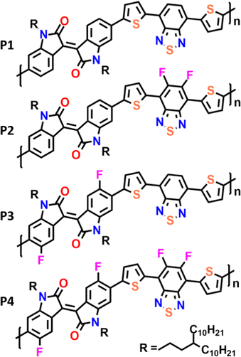
Here we present the synthesis and characterization of a novel series of polymeric materials composed of isoindigo and benzothiadiazole with a flanking thiophene (T) monomeric building block (Fig. 1). In our study, we compare the fluorination of IIG and BT units in order to analyze the effect of intramolecular interactions on the materials’ electrical performances. The impact of progressive fluorination on the optoelectronic properties of these polymers has been rationalized through combined spectroscopic (UV-vis-NIR and Raman), electrochemical and DFT calculations. We hope that the results of this study pave the way for the subtle control of the degree of backbone π-conjugation, intra and interchain interactions as well as thin-film morphologies, which are of fundamental importance for designing new derivatives with improved semiconducting performance.
Results and discussion
Synthesis and characterization
The copolymers P1–P4 were synthesized via cross-coupling polymerization as described in the ESI† (Scheme S1). The number average molecular weights (Mn) and polydispersities (Đ) of the copolymers P1–P4 were measured, resulting in moderately high molecular weights in the range of Mn = 21–32 KDa with a Đ of 2.0–2.1 (Table 1).| M n (kDa) | Đ | λ max sol (nm) | λ max ilm (nm) | E HOMO (eV) | E LUMO (eV) | E elg (eV) | E optg (eV) | |
|---|---|---|---|---|---|---|---|---|
| a Determined by gel permeation chromatography (against polystyrene standards) in chlorobenzene at 80 °C. b λ max in 10−4 M chlorobenzene dilute solution. c Spin-coated from the chlorobenzene solution onto a glass surface. d E HOMO/ELUMO = [−(Eonset – Eonset (Fc/Fc+vs. Ag/Ag+)) − 4.8] eV, where 4.8 eV is the energy level of ferrocene below the vacuum level and the formal potential Eonset (Fc/Fc+vs. Ag/Ag+) is equal to 0.46 V. e Electrochemical bandgap: Eelg = Eox/onset − Ered/onset. f Optical bandgap: Eoptg = 1240/λedge. | ||||||||
| P1 | 21 | 2.0 | 633 | 637 | −4.81 | −3.19 | 1.62 | 1.55 |
| P2 | 24 | 2.0 | 614 | 630 | −4.99 | −3.28 | 1.71 | 1.63 |
| P3 | 32 | 2.1 | 636 | 642 | −5.05 | −3.36 | 1.69 | 1.50 |
| P4 | 29 | 2.1 | 634 | 637 | −5.17 | −3.46 | 1.71 | 1.61 |
Density functional theory calculations
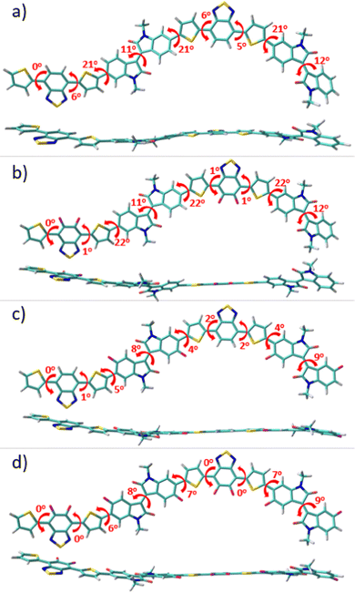
To gain a perception of the effect of progressive fluorination on the molecular ground-state geometry, with the aim of understanding the intra- and intermolecular interplay interactions, packing motifs and charge transport properties, DFT calculations were performed. Since backbone conformation strongly depends on the rotational freedom of the single bonds connecting the (hetero)arene moieties, a preliminary conformational analysis for the monomeric units of P1–P4 polymers was carried out (see Fig. S1, ESI†). Once the most stable conformation of each system was characterized, monomeric units were next linked to create dimeric models corresponding to the respective P1–P4 backbones, which were studied at the B3LYP/6-31G** level of theory, as shown in Fig. 2. Note that the calculations were double checked using the ωB97X-D functional, and the results, which are comparable to the B3LYP ones, are presented in the ESI† (Fig. S2).The results obtained indicate a lack of severe distortions in the conjugated skeleton of the parent P1 copolymer, with dihedral angles that fluctuate between 0 and 21°.
Fluorination of the BT unit in P2 produces a slight planarization of the dihedral angle between the acceptor moiety and the adjacent thiophene rings compared to the nonfluorinated counterparts (from 6° for P1 to 1° for P2). This can be attributed to the through-space interaction between the sp2 lone pair electrons of the fluorine atoms and the C–S antibonding orbitals of the adjacent thiophene ring.34,35 Note that the most notable distortions in P1 and P2 were observed between the IIG acceptor moiety and the adjacent thiophene ring, where no sulfur–fluorine (S⋯F) interactions are possible. However, after fluorination at the α-position of this acceptor IIG unit, this dihedral angle was significantly decreased from 22° in P1 to 4° in P3, demonstrating the presence of additional S⋯F interactions, that further planarize the conjugated skeleton in P3. Interestingly, the fluorination in P3 not only has a notorious effect on the aforementioned interring torsional angle, but it also has a slight effect on the internal planarization of the IIG acceptor unit, with torsional angles of 12° and 9° for P1 and P3, respectively. Following the progressive fluorination of the polymer backbone, the tetra-fluorinated P4 copolymer shows an almost planar skeleton due to the cooperative effects which are observed for the di-fluorinated P2 and P3 systems, with dihedral angles that fluctuate between 0 and 9°. It should be noted that polymer coplanarity is directly related to the percentage of backbone fluorination due to intramolecular interactions. In fact, the presence of S⋯F intramolecular noncovalent interactions on the D–A units can be confirmed by the fact that the calculated S⋯F distances for the IIG-T and BT-T units are significantly shorter (2.73 Å) than the sum of the van der Waals radii for S⋯F (3.27 Å). In summary, the higher the degree of fluorination, the more coplanar the polymer backbone, and this effect is especially remarkable when fluorine atoms are introduced into the IIG acceptor units.
Progressive fluorination may also have an impact on the chemical aromaticity and electronic delocalization of the materials. To analyse this, the successive single-double CC bond length alternation (BLA), as an aromaticity criterion, was calculated for the dimeric models. In this sense, BLA values closer to zero indicate an increasing quinoidization.
On the basis of the calculated data, shown in Fig. S3 (ESI†), the aromaticity of these systems is significantly affected by the fluorination degree which translates into a modulation of the π-conjugation extent. In particular, when compared to the reference P1 copolymer, the DFT-calculated BLA values show a gradual increment of the quinoidal character for the thiophene ring localized between both the IIG and BT acceptor moieties upon progressive fluorination (with BLATh values range from 0.030 ppm for P1 to 0.018 ppm for P4), while the acceptor groups still retain its partial aromatic character. This can be explained in terms of the coplanarity enhancement going from P1 to P4, as previously pointed out, which improves the electronic delocalization in consonance with the more quinoid-like structure of the polymeric backbone upon fluorination.
The enhanced coplanarity and π-conjugation upon fluorination, observed in the studied compounds, can have intra- and intermolecular effects, directly affecting the molecular and electronic properties, molecular packing and active layer morphology, which we will discuss in detail below.
Optical properties
A comparison of the UV-vis-NIR absorption spectra for the four copolymers, P1–P4, in both solution and thin film states is depicted in Fig. 3, and relevant data are summarized in Table 1. The experimental absorption spectra were rationalized with the help of time-dependent DFT (TD-DFT) calculations, and the simulated UV-vis absorption spectra are shown in Fig. S4 and S5 of the ESI.† All the polymers exhibit similar spectral profiles with typically dual-absorption bands (Bands I and II) in solution and thin film states. The most intense absorption band, extending from 400 to 800 nm, is mainly attributed to a one-electron excitation from the highest occupied molecular orbital (HOMO) delocalized over the π-conjugated backbone to the LUMO mainly localized on both the IIG and BT acceptor moieties. The absorption in both solution and solid states follows the same trend. Scrutiny of the spectra reveals that the maximum absorption wavelength (λmax) of P2 was blueshifted (7 and 16 nm for the solution and solid state, respectively) compared with the parent P1 (see Table 1). The observed behaviour was contrary to the expected one, since fluorine atoms are strongly electron-withdrawing with an induction effect, and consequently the acceptor ability should have been enhanced. However, in this case the introduction of the fluorine atoms into the BT unit has a greater stabilization effect on the HOMO (0.18 eV) than on the LUMO energy level (0.09 eV), giving rise to an increase in the optical bandgap (see Table 1).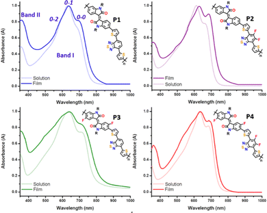 | ||
| Fig. 3 UV-vis absorption spectra of 10−4 M chlorobenzene solution vs. thin film for copolymers P1–P4. | ||
In contrast, the inductive effect of the fluorine atoms introduced into the IIG unit in P3 has an opposite effect, resulting in the lowest optical bandgap across the series (1.50 eV). This indicates the increase of the electron withdrawing ability of the IIG acceptor, which is confirmed by the slight bathochromic shift (of around 3–5 nm) observed in P3 with respect to the non-fluorinated copolymer P1.23,36 These two effects are cooperative in P4, as the measured optical bandgap with a value of 1.61 eV is in between those for the partially fluorinated P2 (1.63 eV) and P3 (1.50 eV) polymers.
It is well known that for conjugated polymers, intermolecular stacking and conformational changes may significantly shift the absorption spectra and change the vibrational peak intensities.37 Interestingly, all the copolymers have structured vibrational absorption peaks in the Band I region with three obvious vibrational peaks 0–0, 0–1 and 0–2, in both solution and as cast thin films. The gradual increase of the fluorine functionality increases 0–0 and decreases 0–1 peak intensity in both dilute solution and thin film, suggesting that fluorination promotes the planarization of the polymer backbone, which is in good agreement with the molecular modelling results. Furthermore, the main absorption peaks of all the copolymers are red shifted going from the solution to the film state, indicating a further planarization of the polymer backbone in the solid state. This is achieved to a maximum effect for the P2 copolymer, where a bathochromic shift of 16 nm from the solution to the film state can be observed, suggesting that the P2 copolymer might adopt a more different molecular conformation and supramolecular organization in the solid state, although they have very similar conjugated backbones. It is worth noting that the relative intensity of the 0–2 vibrational peak of the IIG-fluorinated copolymers (P3 and P4) increases in films when compared to the solution state, being almost negligible in the case of P1 and P2. This phenomenon may be due to the more coplanar copolymer backbone of P3 and P4, resulting in stronger inter-chain interactions, which usually echoes with a highly ordered crystallinity in the solid state. This fact highlights the importance of the fluorination on the IIG acceptor unit in the molecular packing, in accordance with further atomic force microscopy (AFM) and grazing incident X-ray diffraction (GIXRD) analysis.
Polymer electrochemical properties
For high-mobility balanced ambipolar polymers, charge (hole or electron) injection should be feasible from source and drain electrodes. In this regard, charge injection was evaluated by analysing the frontier molecular orbital (FMO) energy levels, including the HOMO (EHOMO) and the LUMO (ELUMO) energy levels, obtained from cyclic voltammetry (CV) measurements (Fig. 4). Notably, all the copolymers exhibited considerable oxidation and reduction peaks (Fig. 4a), being amphoteric redox materials. The EHOMO and ELUMO were calculated from the onsets of oxidation and reduction potentials in comparison with the ferrocene oxidation/reduction potential under a vacuum of −4.80 eV as determined from the equation E = −[e (Eonset − EFC1/2) + 4.80 eV] and are shown in Fig. 4b.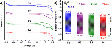 | ||
| Fig. 4 (a) Cyclic voltammograms as a thin film (scan rate 100 mV s−1) and (b) HOMO–LUMO energy levels of the copolymers P1–P4. | ||
It is found that fluorination of the IIG unit induces a much more pronounced deepening of the HOMO and LUMO energy levels than fluorination on the BT acceptor unit. In particular, fluorination of the BT acceptor unit in P2 further stabilizes the HOMO with respect to the LUMO, leading to a higher band gap (Eelg) with respect to the P1 counterpart (1.62 eV for P1vs. 1.71 eV for P2), as previously found in the absorption spectra and in the theoretical calculations. In contrast, both the HOMO and LUMO energy levels of P3 (Eg = 1.69 eV) are lowered to a similar extent with respect to those of P1. Further extended fluorination degree in copolymer P4 leads to the lowest HOMO and LUMO energy levels, which are −5.17 and −3.46 eV, respectively. The Eelg of P4 was estimated to be 1.71 eV, similar to that of the BT-fluorinated P2 copolymer.
The FMO topologies plotted in Fig. 5 show that both the HOMO and the LUMO present remarkable contributions to the IIG and BT acceptor units, thus explaining the deepening of both orbitals upon fluorination.
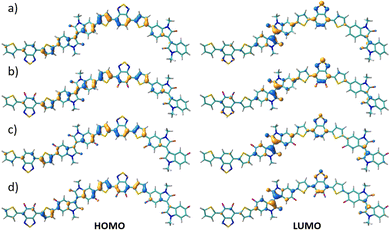 | ||
| Fig. 5 DFT-calculated HOMO (right) and LUMO (left) topologies for the dimeric models of P1 (a), P2 (b), P3 (c) and P4 (d) polymers at the B3LYP/6-31G** level of theory. | ||
DFT calculated data gave similar trends of HOMO and LUMO energy levels within the series of copolymers (see Fig. S6–S9, ESI†).
Their strong oxidation peaks, in addition to their high-lying HOMO levels (<−4.80 eV), suggest that these polymers may be useful for developing p-channel OFETs. Furthermore, some of the fluorinated polymers may be useful as semiconductors for ambipolar OFETs due to their low-lying LUMO levels (<−3.30 eV) and their quasi-reversible reduction peaks. With the above considerations, adjusting the fluorination degree would be advantageous for tuning the electronic energy levels and reducing the band gaps of the resulting materials.
OFET charge transport characterization
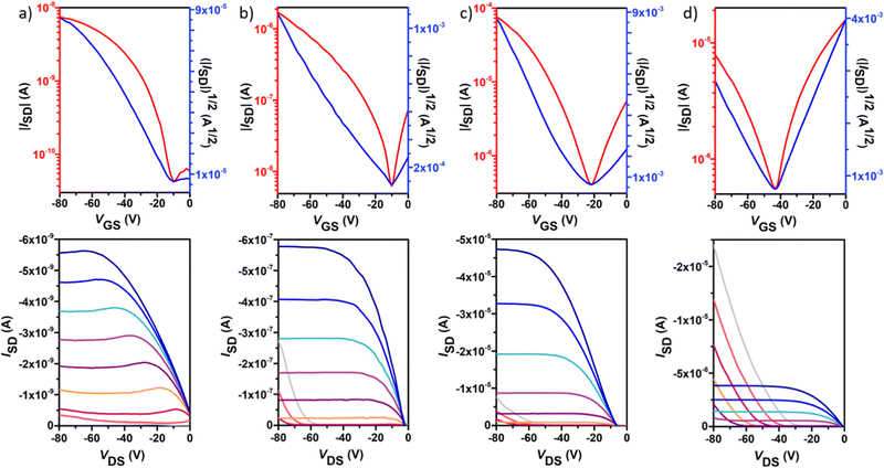
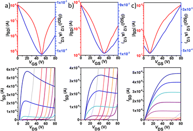
Polymer OFETs were prepared using a bottom-gate top-contact (BG-TC) device structure to investigate the effect of fluorination on the charge transport characteristics. In each case, the device performance was systematically optimized by modifying substrate treatment and annealing conditions (see the ESI† for the exact OFET fabrication details). The representative transfer and output curves, measured under vacuum conditions for the best-performing devices, are illustrated in Fig. 6 and Fig. 7, and the corresponding device performance parameters, extracted from transfer curves in the saturated regime, which include hole mobilities (μh), electron mobilities (μe), threshold voltages (VT) and on–off intensity ratios (Ion/Ioff), are summarized in Table 2 and Tables S1–S4 in the ESI.†P1 shows typical p-channel behaviour with a modest hole mobility of ∼10−5 cm2 V−1 s−1 and an Ion/Ioff ratio of 102. The low mobility can be attributed to the slightly lower molecular weight, higher energy band gap and a substantial backbone torsion that produces inefficient orbital overlapping and thus low electronic coupling, which is detrimental to efficient charge transport in OFET devices.38,39 The incorporation of fluorine atoms into the backbone enhances the polymer coplanarity and electron affinity, thus decreasing the electron-injection barrier from the gold electrode to the organic semiconducting layers. Consequently, the electronic properties change from a low hole-dominated to a balanced ambipolar charge transport on going from P1 to P4. As a result, typical V-shaped transfer curves and characteristic output curves of ambipolar OFETs were recorded. The latter is characterized by the superposition of standard saturation behaviour for one type of carrier at a high gate voltage (VG) and a superlinear current increase at a low VG and high source–drain voltage (VDS), due to the injection of the opposite carriers. Most importantly, weak dependence of both μh and μe on VG was also observed. Besides no contact resistance was detected in the output curves, suggesting a good contact between the polymer and the gold electrode.| p-channel | n-channel | |||||||
|---|---|---|---|---|---|---|---|---|
| μ h (cm2 V−1 s−1) | I on/Ioff | V T (V) | Method | μ e (cm2 V−1 s−1) | I on/Ioff | V T (V) | Method | |
| P1 | 1.1 × 10⁻⁵(1.4 × 10⁻⁵) | 8 × 101(1 × 10²) | 4(−3) | OTS, 150 °C, 2 h | — | — | — | — |
| P2 | 2.9 × 10⁻³(3.3 × 10⁻³) | 1 × 10³(2 × 10³) | −1(−17) | OTS, 150 °C, 2 h | 3.8 × 10⁻³(4.0 × 10⁻³) | 4 × 10³(9 × 10³) | 58(52) | OTS, 150 °C, 2 h |
| P3 | 1.2 × 10⁻¹(1.5 × 10⁻¹) | 2 × 10²(4 × 10²) | −26(−31) | OTS, 200 °C, 2 h | 9.8 × 10⁻²(1.1 × 10⁻¹) | 8 × 101(1 × 10²) | 57(53) | OTS, 200 °C, 2 h |
| P4 | 3.3 × 10⁻²(7.4 × 10⁻²) | 1 × 10⁵(4 × 10⁵) | −11(−29) | OTS, 150 °C, 2 h | 1.1 × 10⁻²(1.3 × 10⁻²) | 2 × 10³(7 × 10³) | 17(8) | OTS |
In contrast to the reference copolymer P1, the di-fluorinated copolymer P2 exhibited well-balanced ambipolar transport characteristics (μh/μe = 0.82), with hole and electron mobilities of 3.3 × 10⁻³ and 4.0 × 10⁻³ cm2 V−1 s−1 respectively, and an Ion/Ioff ratio of 103 in both p- and n-channel operations.
Among the four polymers, P3 exhibited the highest and well-balanced ambipolar charge-transport characteristic (μh/μe = 1.36) with hole and electron mobilities of 0.145 and 0.106 cm2 V−1 s−1, respectively (approximately 2 orders of magnitude higher than those of the P2-based copolymer), on account of its high molecular weight, low energy band gap and high backbone planarity. An Ion/Ioff ratio of 102 in both p- and n-channel operations was measured for P3. To the best of our knowledge, this is one of the best balanced ambipolar performances in terms of the electron and hole mobilities among the solution processed OFETs prepared with IIG-based polymers in a BG-TC device structure.17,40–43 However, further extended fluorination degree in P4 reduces the OFET performance, with hole mobilities nearly 5-fold higher than electron mobilities (0.07 vs. 0.01 cm2 V−1 s−1, respectively), even though their lower energy levels and slightly increased coplanarity than those of P3. This fact suggests that other factors such as solid-state morphology are also influencing the charge transport properties. Moderately high Ion/Ioff ratios of 105 and 103 were found for P4 for p- and n-channel operations, respectively, which is considered to be important for applications of ambipolar OFETs in complementary logic circuits.44
Thin-film morphology characterization
To clarify the effect of fluorination on the device performance, the microstructure of the thin films, under the deposition conditions that render the best device performances, was first characterized via GIXRD, as depicted in Fig. 8. Note that even when the films are quite amorphous, the moderate film crystallinity is directly related to the amount of fluorine atoms incorporated into the polymeric backbone. In particular, the non-fluorinated copolymer P1 shows an amorphous nature in the film state, whereas a certain degree of crystallinity appears for all the fluorinated systems. Hence, the fluorinated copolymers P2, P3 and P4 present a main lamellar (100) reflection at 2θ = 3.28, 3.64 and 3.10° corresponding to interchain distances (d100) of 26.92, 24.25 and 28.48 Å, respectively. A peak corresponding to π–π stacking was not observed in the GIXRD patterns of polymer thin films, suggesting that these copolymers self-organize into lamellar planes consisting of edge-on orientations relative to the substrate, which is beneficial for charge transport along the horizontal transport channel in BGTC OFETs. The smallest d100 values were observed for P3, improving the interchain charge transport for OFETs, and thus exhibiting higher mobilities.45 Interestingly, a second diffraction peak at 2θ = 4.24° (d100 = 20.82 Å) can be observed for films of P3. The higher crystalline tendency upon the progressive fluorination has been attributed to the increment of torsional barriers between the subunits, limiting rotation and enforcing coplanarity, effects that lead to a better molecular packing in the solid state. These factors were recognized here in the computational analysis, showing almost flat polymer backbones for P3 and P4 in line with their slightly enhanced crystallinities.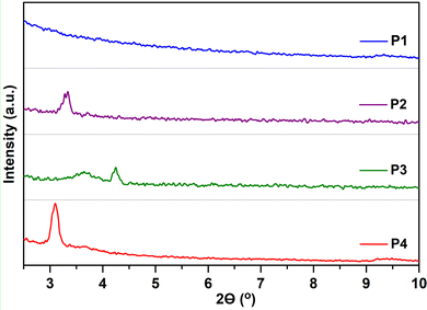 | ||
| Fig. 8 GIXRD patterns of P1–P4 thin films prepared under optimal device performance conditions. An intensity spectral range from 0 to 350 a.u. was used for all polymers. | ||
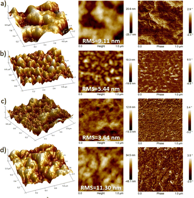
AFM images also support that fluorinated polymers display higher homogeneous texture, in comparison with their non-fluorinated counterparts which present a poor uniformity with larger deformations on the surface (Fig. 9). However, discernible differences in the domain shape and size were observed for each fluorinated polymer. It is generally known that well interconnected large domains can minimize crystalline grain boundaries, leading to higher OFET mobilities.46 In this sense, the higher OFET performance of P3 devices can be explained by their higher homogeneity (with an RMS of 3.64 nm), as a result of a better interconnection of the crystalline domains and thus soft grain boundaries. For films of P2, although bigger size polymer grains can be observed, their surface height and angle vary by a higher extent compared to that of P3, reducing the OFET performance of the devices. Similarly, P4 films clearly displayed larger surface roughness (RMS = 11.30 nm) and domain sizes compared to the P3 analog, presumably due to the high degree of self-assembly and thus higher crystallinity of P4, which is consistent with the GIXRD results. These differences can be observed in the 3D-topography images presented for the polymers and may account for the lower hole and electron mobilities measured in P4-based OFETs with respect to those of P3. This fact corroborates that larger irregularities and bigger grain domains in the film surface, such as in P4, are detrimental, in this case, for BG-TC OFET devices.47
Thermal annealing at different temperatures resulted in negligible changes in film morphologies (see Fig. S15–S26, ESI†). These considerations indicate that the introduction of fluorine atoms not only modulates the energy levels, but also influences the interchain interactions of polymers, creating different polymer packings in the solid state. Therefore, the difference in crystallinity between the polymers under study may also support the differences found in device performances.
Raman spectroscopy study
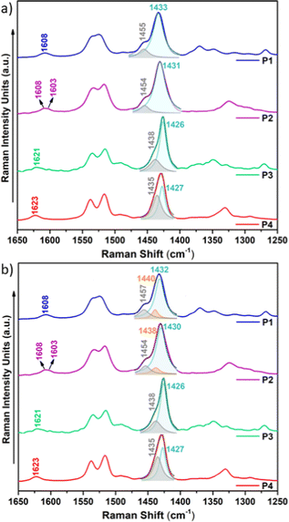
Raman spectroscopy is considered a useful tool that renders valuable intramolecular information, such as conjugational degree, skeleton planarity, etc. but also provides indirect information on intermolecular properties, allowing the analysis of ordered and disordered phases within films. Therefore, we recorded the Raman spectra of P1–P4 copolymers as solid powders and as thin films (Fig. 10 and Fig. S28–S30, ESI†) prepared under optimal device performance conditions.Fig. 10 shows the FT-Raman spectra of P1–P4 copolymers as solid powders. First, we will focus our attention on the two representative Raman bands: (i) the most intense Raman peak, recorded at 1433–1426 cm−1 and, as seen in the eigenvectors in Fig. S32–S35 (ESI†), ascribed to a symmetric normal mode mostly located on the thiophene rings including the BT acceptor unit (highlighted in light blue in Fig. 10a) and (ii) the band recorded at 1455–1435 cm−1, corresponding to a normal mode located on the IIG acceptor moiety (highlighted in grey in Fig. 10a). As seen in Fig. S31 (ESI†), this second band is predicted to gain intensity and gradually merge with the most intense Raman band on going from P1–P2 to P3–P4, perfectly agreeing with the experimental data, where it is recorded as a high energy shoulder for P3 and P4 polymers.
Note however that the most intense Raman band is found to be wider for P1 and P2 copolymers, indicating the presence of different phases within the sample, which may include disordered and ordered phases. In order to prove this, a deconvolution of the band was attempted and it was found that the fitting is optimal when two different components are assumed for polymers P1 and P2, while a single component, due to the presence of only an ordered phase, is needed for the fitting of polymers P3 and P4 (Fig. 10b). Therefore, Raman spectra indicate that fluorination of the BT unit is not enough to significantly increase the supramolecular order within the sample, while fluorination on the IIG unit is a much more effective way to promote skeleton planarity.
This also becomes evident by the comparison of the Raman spectra recorded upon excitation with different laser wavelengths (Fig. 11). Note that when using 473 nm, 532 nm or 633 nm wavelengths, resonance conditions occur with more disordered or less planar copolymer skeletons (see Fig. S27, ESI†), and thus, their Raman signal should be enhanced. This was actually observed for P1 and P2 copolymers, being more evident in the former. In particular, the contribution in the P1 copolymer (Fig. 11a) corresponding to the more disordered phase, registered at around 1440 cm−1, substantially increases its intensity when using high energy wavelength lasers. This also happens in copolymer P2 (Fig. 11b), although in this case the increase is less obvious, indicating some skeletal planarization due to the insertion of the fluorine atoms on the BT unit. However, no disordered phases were observed for copolymers P3 and P4, independently of the wavelength used, thus, indicating efficient skeleton planarity.
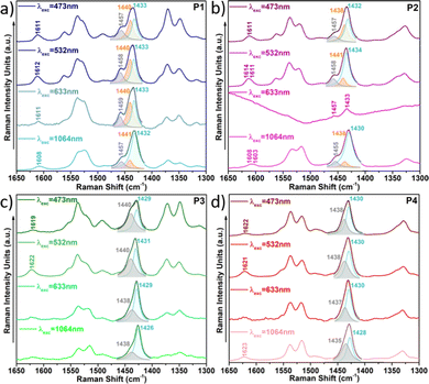 | ||
| Fig. 11 Resonance Raman spectra of copolymers P1 (a), P2 (b), P3 (c) and P4 (d) under different laser excitations. | ||
Other details, found in the Raman spectra, also support the planarization induced by the addition of fluorine moieties, as seen in Fig. 10:
(i) As fluorine atoms are sequentially introduced into the conjugated skeleton, the most intense Raman band not only sharpens but also gradually downshifts, indicating a higher π-conjugation degree conferred by the planarization induced by the presence of S⋯F interactions. The most remarkable downshift of 7 cm−1 is recorded for P3, where the fluorine atoms are located on the IIG acceptor unit. Therefore, fluorination on this monomeric unit is the most effective approach to induce planarity and increase π-conjugation.
(ii) The Raman band recorded at 1454 cm−1 for the copolymer P1 (corresponding to a normal mode located on the IIG acceptor moiety) greatly downshifts for copolymers P3 and P4 (by approx. 17–20 cm−1) where the fluorine atoms planarize the IIG unit and the neighbouring thiophene rings. In contrast, a slight downshift of only 3 cm−1 is recorded for P2 with respect to P1, which is in consonance with the moderate backbone planarization when the fluorine atoms are included on the BT acceptor unit (Fig. 2).
(iii) The Raman band corresponding to the ν(C![[double bond, length as m-dash]](https://www.rsc.org/images/entities/char_e001.gif) O) vibration, recorded at ca. 1608 cm−1 in P1, significantly upshifts in P3 and P4 (by 13–15 cm−1). This is due to a much improved intrachain π-electronic delocalization due to planarization, which diminishes the cross-conjugation in the IIG moiety.
O) vibration, recorded at ca. 1608 cm−1 in P1, significantly upshifts in P3 and P4 (by 13–15 cm−1). This is due to a much improved intrachain π-electronic delocalization due to planarization, which diminishes the cross-conjugation in the IIG moiety.
Conclusions
A series of D–A copolymers consisting of 4,7-di(2-thienyl)-2,1,3-benzothiadiazole and isoindigo building blocks have been synthesized and characterized by means of spectroscopic (UV-vis-NIR and Raman) and electrochemical techniques combined with DFT calculations. We have demonstrated herein that sequential fluorination of the monomeric building blocks not only stabilizes the frontier molecular orbitals but also partially locks the polymer conjugated skeletons through S⋯F non-covalent interactions. However, the impact of the gradual fluorination on the electronic properties is highly dependent on the building blocks into which the fluorine atoms are introduced. In this sense, Raman spectroscopy has been used to analyse both ordered and disordered phases of the polymeric samples upon gradual increase of fluorine atoms. The results indicate that fluorination of the BT unit is not enough to significantly increase the supramolecular order within the sample, while fluorination on the IIG unit is a much more effective way to promote skeleton planarity and enhance π-conjugation.Electrical characterization in OFETs further supports that fluorination progressively increases the polymer coplanarity and electron affinity, varying the electrical performance from a low hole dominated charge transport in P1 to a balanced ambipolar charge transport in P2–P4. The best performance was recorded for the most effective-locked P3 copolymer, with remarkably balanced hole and electron field-effect mobilities of ∼0.1 cm2 V−1 s−1. The higher degree of molecular locking in P4 renders less efficient OFETs, which is ascribed to the slightly decreased molecular weight and morphology effects.
Author contributions
Sergio Gámez-Valenzuela: investigation, data curation, visualization, writing – original draft, and writing – review & editing. Marc Comi: investigation, data curation, visualization, writing – original draft, and writing – review & editing. Sandra Rodríguez González: investigation, data curation, visualization, and writing – review & editing. M. C. Ruiz Delgado: investigation, data curation, visualization, writing – review & editing, funding acquisition, and project administration. Mohammed Al-Hashimi: conceptualization, investigation, data curation, visualization, writing – review & editing, funding acquisition, and project administration. Rocío Ponce Ortiz: conceptualization, investigation, data curation, visualization, supervision, writing – review & editing, funding acquisition, and project administration.Conflicts of interest
There are no conflicts to declare.Acknowledgements
The work at the University of Málaga was supported by the MICINN (project PID2019-110305GB-I00) and by Junta de Andalucía (project P18-FR-4559). S. G.-V. thanks the MINECO for an FPU predoctoral fellowship (FPU17/04908). The authors would like to thank the computer resources, technical expertise and assistance provided by the SCBI (Supercomputing and Bioinformatics) centre of the University of Málaga. The Vibrational spectroscopy (EVI), XRD and AFM labs of the Research Central Services (SCAI) of the University of Málaga are also gratefully acknowledged. Al-Hashimi likes to acknowledge the financial support from the Qatar National Research Fund, Project Number NPRP12S-0304-190227.Notes and references
- Y. Yao, H. Dong and W. Hu, Adv. Mater., 2016, 28, 4513–4523 CrossRef CAS PubMed.
- J. Xu, S. Wang, G.-J. N. Wang, C. Zhu, S. Luo, L. Jin, X. Gu, S. Chen, V. R. Feig, J. W. F. To, S. Rondeau-Gagné, J. Park, B. C. Schroeder, C. Lu, J. Y. Oh, Y. Wang, Y.-H. Kim, H. Yan, R. Sinclair, D. Zhou, G. Xue, B. Murmann, C. Linder, W. Cai, J. B.-H. Tok, J. W. Chung and Z. Bao, Science, 2017, 355, 59–64 CrossRef CAS PubMed.
- S. E. Root, S. Savagatrup, A. D. Printz, D. Rodriquez and D. J. Lipomi, Chem. Rev., 2017, 117, 6467–6499 CrossRef CAS PubMed.
- I. Imae and K. Krukiewicz, Bioelectrochemistry, 2022, 146, 108127 CrossRef CAS PubMed.
- Y. Wu, C. Shi, G. Wang, H. Sun and S. Yin, J. Mater. Chem. B, 2022, 10, 2995–3015 RSC.
- X. Ma, Z. Jiang, L. Xiang and F. Zhang, ACS Mater. Lett., 2022, 4, 918–937 CrossRef CAS.
- S. R. Forrest, Nature, 2004, 428, 911–918 CrossRef CAS PubMed.
- A. C. Arias, J. D. MacKenzie, I. McCulloch, J. Rivnay and A. Salleo, Chem. Rev., 2010, 110, 3–24 CrossRef CAS PubMed.
- Y. Diao, L. Shaw, Z. Bao and S. C. B. Mannsfeld, Energy Environ. Sci., 2014, 7, 2145–2159 RSC.
- Q. Liu, S. E. Bottle and P. Sonar, Adv. Mater., 2020, 32, 1903882 CrossRef CAS PubMed.
- S. Attar, R. Yang, Z. Chen, X. Ji, M. Comí, S. Banerjee, L. Fang, Y. Liu and M. Al-Hashimi, Chem. Sci., 2022, 13, 12034–12044 RSC.
- Z. Chen, J. Li, J. Wang, K. Yang, J. Zhang, Y. Wang, K. Feng, B. Li, Z. Wei and X. Guo, Angew. Chem., Int. Ed., 2022, 61, e202205315 CAS.
- M. Comí, M. U. Ocheje, S. Attar, A. U. Mu, B. K. Philips, A. J. Kalin, K. E. Kakosimos, L. Fang, S. Rondeau-Gagné and M. Al-Hashimi, Macromolecules, 2021, 54, 665–672 CrossRef.
- M. Comí, D. Patra, R. Yang, Z. Chen, A. Harbuzaru, Y. Wubulikasimu, S. Banerjee, R. Ponce Ortiz, Y. Liu and M. Al-Hashimi, J. Mater. Chem. C, 2021, 9, 5113–5123 RSC.
- M. U. Ocheje, M. Comí, R. Yang, Z. Chen, Y. Liu, N. Yousefi, M. Al-Hashimi and S. Rondeau-Gagné, J. Mater. Chem. C, 2022, 10, 4236–4246 RSC.
- M. Comí, S. Moncho, S. Attar, M. Barłóg, E. Brothers, H. S. Bazzi and M. Al-Hashimi, Macromol. Rapid Commun., 2022, 2200731 CrossRef PubMed.
- X. Wei, W. Zhang and G. Yu, Adv. Funct. Mater., 2021, 31, 2010979 CrossRef CAS.
- G. Kim, S.-J. Kang, G. K. Dutta, Y.-K. Han, T. J. Shin, Y.-Y. Noh and C. Yang, J. Am. Chem. Soc., 2014, 136, 9477–9483 CrossRef CAS PubMed.
- Y.-Q. Zheng, T. Lei, J.-H. Dou, X. Xia, J.-Y. Wang, C.-J. Liu and J. Pei, Adv. Mater., 2016, 28, 7213–7219 CrossRef CAS PubMed.
- B. Liu, Y. Wang, H. Sun, S. Gámez-Valenzuela, Z. Yan, K. Feng, M. A. Uddin, C. Koh, X. Zhou, J. T. López Navarrete, M. C. Ruiz Delgado, H. Meng, L. Niu, H. Y. Woo, R. Ponce Ortiz and X. Guo, Adv. Funct. Mater., 2022, 32, 2200065 CrossRef CAS.
- T. Dong, L. Lv, L. Feng, Y. Xia, W. Deng, P. Ye, B. Yang, S. Ding, A. Facchetti and H. Dong, Adv. Mater., 2017, 29, 1606025 CrossRef PubMed.
- J. Yuan, M. J. Ford, Y. Zhang, H. Dong, Z. Li, Y. Li, T.-Q. Nguyen, G. C. Bazan and W. Ma, Chem. Mater., 2017, 29, 1758–1768 CrossRef CAS.
- J. Yang, Z. Zhao, H. Geng, C. Cheng, J. Chen, Y. Sun, L. Shi, Y. Yi, Z. Shuai, Y. Guo, S. Wang and Y. Liu, Adv. Mater., 2017, 29, 1702115 CrossRef PubMed.
- Y. Gao, Y. Deng, H. Tian, J. Zhang, D. Yan, Y. Geng and F. Wang, Adv. Mater., 2017, 29, 1606217 CrossRef PubMed.
- T. Lei, X. Xia, J.-Y. Wang, C.-J. Liu and J. Pei, J. Am. Chem. Soc., 2014, 136, 2135–2141 CrossRef CAS PubMed.
- D. M. DeLongchamp, R. J. Kline and A. Herzing, Energy Environ. Sci., 2012, 5, 5980–5993 RSC.
- G. Paternò, A. J. Warren, J. Spencer, G. Evans, V. G. Sakai, J. Blumberger and F. Cacialli, J. Mater. Chem. C, 2013, 1, 5619–5623 RSC.
- Y. Wang, H. Guo, A. Harbuzaru, M. A. Uddin, I. Arrechea-Marcos, S. Ling, J. Yu, Y. Tang, H. Sun, J. T. López Navarrete, R. P. Ortiz, H. Y. Woo and X. Guo, J. Am. Chem. Soc., 2018, 140, 6095–6108 CrossRef CAS PubMed.
- J. Kim, K.-J. Baeg, D. Khim, D. T. James, J.-S. Kim, B. Lim, J.-M. Yun, H.-G. Jeong, P. S. K. Amegadze, Y.-Y. Noh and D.-Y. Kim, Chem. Mater., 2013, 25, 1572–1583 CrossRef CAS.
- W. C. Tsoi, D. T. James, J. S. Kim, P. G. Nicholson, C. E. Murphy, D. D. C. Bradley, J. Nelson and J.-S. Kim, J. Am. Chem. Soc., 2011, 133, 9834–9843 CrossRef CAS PubMed.
- W. C. Tsoi, D. T. James, E. B. Domingo, J. S. Kim, M. Al-Hashimi, C. E. Murphy, N. Stingelin, M. Heeney and J.-S. Kim, ACS Nano, 2012, 6, 9646–9656 CrossRef CAS PubMed.
- S. Wood, J.-H. Kim, J. Wade, J. B. Park, D.-H. Hwang and J.-S. Kim, J. Mater. Chem. C, 2016, 4, 7966–7978 RSC.
- N. Zhou, X. Guo, R. P. Ortiz, T. Harschneck, E. F. Manley, S. J. Lou, P. E. Hartnett, X. Yu, N. E. Horwitz, P. M. Burrezo, T. J. Aldrich, J. T. López Navarrete, M. R. Wasielewski, L. X. Chen, R. P. H. Chang, A. Facchetti and T. J. Marks, J. Am. Chem. Soc., 2015, 137, 12565–12579 CrossRef CAS PubMed.
- H. Huang, Z. Chen, R. P. Ortiz, C. Newman, H. Usta, S. Lou, J. Youn, Y.-Y. Noh, K.-J. Baeg, L. X. Chen, A. Facchetti and T. Marks, J. Am. Chem. Soc., 2012, 134, 10966–10973 CrossRef CAS PubMed.
- K. J. Thorley and I. McCulloch, J. Mater. Chem. C, 2018, 6, 12413–12421 RSC.
- T. Lei, J.-H. Dou, Z.-J. Ma, C.-H. Yao, C.-J. Liu, J.-Y. Wang and J. Pei, J. Am. Chem. Soc., 2012, 134, 20025–20028 CrossRef CAS PubMed.
- J. Kim and T. M. Swager, Nature, 2001, 411, 1030–1034 CrossRef CAS PubMed.
- H. Sirringhaus, P. J. Brown, R. H. Friend, M. M. Nielsen, K. Bechgaard, B. M. W. Langeveld-Voss, A. J. H. Spiering, R. A. J. Janssen, E. W. Meijer, P. Herwig and D. M. de Leeuw, Nature, 1999, 401, 685–688 CrossRef CAS.
- I. Osaka, M. Akita, T. Koganezawa and K. Takimiya, Chem. Mater., 2012, 24, 1235–1243 CrossRef CAS.
- G. K. Dutta, A.-R. Han, J. Lee, Y. Kim, J. H. Oh and C. Yang, Adv. Funct. Mater., 2013, 23, 5317–5325 CrossRef CAS.
- G. Zhang, Z. Ye, P. Li, J. Guo, Q. Wang, L. Tang, H. Lu and L. Qiu, Polym. Chem., 2015, 6, 3970–3978 RSC.
- K. Huang, X. Zhao, Y. Du, S. Kim, X. Wang, H. Lu, K. Cho, G. Zhang and L. Qiu, J. Mater. Chem. C, 2019, 7, 7618–7626 RSC.
- J. W. Jo, J. H. Kim and J. W. Jung, Dyes Pigm., 2016, 133, 333–338 CrossRef CAS.
- S. Z. Bisri, C. Piliego, J. Gao and M. A. Loi, Adv. Mater., 2014, 26, 1176–1199 CrossRef CAS PubMed.
- S. H. Eom, S. Y. Nam, H. J. Do, J. Lee, S. Jeon, T. J. Shin, I. H. Jung, S. C. Yoon and C. Lee, Polym. Chem., 2017, 8, 3612–3621 RSC.
- H. N. Tsao and K. Müllen, Chem. Soc. Rev., 2010, 39, 2372–2386 RSC.
- B. J. Eckstein, F. S. Melkonyan, G. Wang, B. Wang, E. F. Manley, S. Fabiano, A. Harbuzaru, R. Ponce Ortiz, L. X. Chen, A. Facchetti and T. J. Marks, Adv. Funct. Mater., 2021, 31, 2009359 CrossRef CAS.
Footnote |
| † Electronic supplementary information (ESI) available: Synthetic details, DFT calculations, spectroscopic and morphologic characterization, electrical characterization. See DOI: https://doi.org/10.1039/d2tc05073k |
| This journal is © The Royal Society of Chemistry 2023 |

