Organic ligand-facilitated in situ exsolution of CoFe alloys over Ba0.5Sr0.5Co0.8Fe0.2O3−δ perovskite toward enhanced oxygen electrocatalysis for rechargeable Zn-air batteries†
Yasir
Arafat
 a,
Muhammad Rizwan
Azhar
b,
Yijun
Zhong
 a,
Ryan
O'Hayre
 c,
Moses O.
Tadé
a and
Zongping
Shao
 *a
*a
aWA School of Mines: Minerals, Energy and Chemical Engineering (WASM-MECE), Curtin University, Perth, Western Australia 6102, Australia. E-mail: zongping.shao@curtin.edu.au
bSchool of Engineering, Edith Cowan University, 270 Joondalup Drive, Joondalup, Western Australia 6027, Australia
cDepartment of Metallurgical and Materials Engineering, Colorado School of Mines, 1500 Illinois St., Golden, CO 80401, USA
First published on 11th November 2022
Abstract
Cobalt-based perovskites are promising electrocatalysts for the oxygen evolution/reduction reaction (OER/ORR), while their surface modification with nanoparticles may further improve the performance. In the past, in situ exsolution of a metal (alloy) over a perovskite surface promoted by a H2 atmosphere has been widely applied in developing nanoparticle modified anode materials for solid oxide fuel cells. However, it is a big challenge to apply this strategy for synthesizing cobalt-rich perovskite oxides for oxygen electrocatalysis due to their poor phase stability under a highly reducing atmosphere. Here, we report another strategy of organic ligand-facilitated in situ exsolution under a N2 atmosphere for developing CoFe nanoalloys over Ba0.5Sr0.5Co0.8Fe0.2O3−δ (BSCF) perovskite as an air electrode for zinc-air batteries (ZABs). The BSCF–CoFe interface, newly generated oxygen vacancies and Co–N–C porous networks provide conduction pathways for oxygen ions and electrons, leading to the enhanced electrochemical bi-functional performance. BSCF/CoFe offers OER activity, while Co–N–C and CoFe contribute to the ORR activity. Interestingly, the exsolved CoFe alloy also considerably promotes the ORR selectivity, leading to a 4e− pathway. Consequently, ZABs integrated with the bi-functional electrocatalyst exhibit a favourable potential gap of 0.835 V at a discharge/charge current density of 5 mA cm−2, and the cell operates stably without obvious degradation for over 250 h.
10th Anniversary StatementProf. Zongping Shao is currently an advisory board member of JMCA. He is a loyal reader and author of the journal. He started to publish papers in JMCA from the first volume once it was launched in 2013, and up to now he has published 54 research and review papers in this journal. He also serves actively as a reviewer for this journal within the areas of fuel cells, batteries, electrocatalysis, hydrogen energy and solar cells. |
Introduction
In the wave of gradual transition from fossil fuels to more sustainable energy resources (viz. solar, wind, etc.), energy storage systems are indispensable to overcome their intermittent nature.1 Over the last few decades, lithium-ion batteries have been intensively developed as power sources for portable electronic devices. More recently, alternative energy storage devices with higher energy density and better cost effectiveness have been highly searched for. Interestingly, metal-air batteries consisting of a metal as an anode and air as an active cathode material have demonstrated high energy density.2,3 The high energy density of metal-air batteries may be associated with the air accessible from the ambient atmosphere because it is not stored inside the cell.4 In this context, Zn-air batteries (ZABs) stand out because of their high theoretical energy density (1350 W h kg−1, about 3 times higher than that of Li-ion batteries), inherent safety, low cost for abundant zinc resources, and the environmental benignity.The operation principle of ZABs involves oxygen redox reactions at the air electrode and zinc redox reactions at the counter electrode. It is now well demonstrated that the sluggish redox reactions at the air electrode mainly limit the capacity and stability of ZABs. During the discharge/charge process, the oxygen reduction reaction (ORR) and oxygen evolution reaction (OER) happen respectively, which are kinetically sluggish because of their four electron transfer nature,5 causing high overpotential and low energy efficiency. The poor air electrode performance has been one of the main obstacles towards the practical application of ZABs in energy sectors. Therefore, it is crucial to design an efficient oxygen electrocatalyst to expedite the bi-functional (OER/ORR) activities.6
In the past, precious metal-based catalysts have been widely exploited for speeding up oxygen redox reactions, and IrO2 (or RuO2) and platinum (Pt), supported on carbon materials, are currently the benchmarks for OER and ORR catalysts, respectively. Nevertheless, these noble metals are exorbitant, scarce and inferior in terms of stability, making them impracticable for commercial purposes for oxygen electrolysis and ZABs. This calls for the development of an alternative cost-effective, precious metal-free, bi-functional electrocatalyst as an air electrode for ZABs, which should possess binary active sites for both the OER and ORR.
Recently, Co-based nonprecious-metal-containing compounds have attracted significant attention as air electrodes for Zn-air batteries.7–10 Notably, perovskite oxides have been recognized as promising oxygen electrocatalysts due to their low cost, tunable composition and favourable activity.11,12 Nevertheless, most of the available perovskite oxides display insufficient bi-functional (OER/ORR) activity. Moreover, some perovskites suffer from low stability and poor electrical conductivity. Therefore, to realize the application of available perovskite materials in ZABs, it is imperative to conduct further fine-tuning of perovskite materials.
Interestingly, in situ metal exsolution has emerged as a promising catalyst design strategy for various applications, including the energy sector.13–15 This ameliorates catalytically active centres and thus the electrocatalytic activity of perovskite-related oxides. Exsolution can selectively induce the dispersion of B-site transition metal atoms over the surface of perovskite or pyrochlore oxides at a high temperature under a reducing atmosphere. As a result, the oxide substrate provides conduction pathways for oxygen ions and electrons, and the exsolved metallic nanoparticles serve as highly active centers.16,17 Notably, the latest research findings have prioritized the exsolution of alloys over exsolved single metals owing to their exceptional features.18,19 For instance, in situ exsolved CoFe nanoalloys decorated on La1−xSrxCo1−yFeyO3−δ (LSCF) perovskite oxides have demonstrated excellent OER activities owing to their fast oxygen surface exchange kinetics.20,21 Their high activity originates from the in situ created metal–oxide interface developed between CoFe alloy nanoparticles and LSCF perovskite (CoFe@LSCF).19,22 Interestingly, the CoFe alloy might function as a bi-functional (OER/ORR) electrocatalyst in conjunction with other materials such as carbon.23–26 However, the co-segregation/exsolution of the CoFe alloy is challenging because the segregation energy of Fe is higher than that of Co. To figure out the segregation energy of transition metals, Kim et al. doped several transition metals into PrBaMn1.7X0.3O5−d (X = Mn, Co, Ni, and Fe) and established that exsolution occurred in the following trend: Mn > Co > Ni > Fe. Thus, cobalt metal is more prone to exsolution, while Fe is the hardest one to be exsolved owing to its highest segregation energy.27,28 Therefore, it requires high thermal treatment under a reducing atmosphere. On the other hand, in situ exsolution of perovskites under highly reducing atmospheres would experience complete reduction, leading to inadequate electrocatalytic performance.16,19 For instance, Song et al. reported CoFe nanoalloys decorated on La2O3 where CoFe nanoalloys were in situ exsolved from LaCo0.8Fe0.2O3−δ.29 The CoFe/La2O3 catalyst displayed notable OER performance via transformation of CoFe nanoalloys into (Co/Fe)O(OH) intermediates in an alkaline medium. It is notable that LaCo0.8Fe0.2O3−δ perovskite was completely disintegrated into OER active sites (CoFe nanoalloys) and OER inactive sites (La2O3). As a result, a synergistic effect could not be developed between the La2O3 support and CoFe nanoalloys. Thus, it is challenging to control the extent of exsolution via conventional thermal H2 reduction.
Herein, we devised a novel approach, allowing the in situ exsolution of CoFe nanoalloys over the surface of Ba0.5Sr0.5Co0.8Fe0.2O3−δ (BSCF), a benchmark perovskite for the OER under a reducing atmosphere,30 while protecting the main perovskite structure. The key point of this strategy is the application of 2-methyl imidazolate (2-MIM), an organic ligand as a mild reducing agent. Such an organic ligand could break the bottleneck of co-exsolution of CoFe alloys, leading to a high level of metal exsolution in a N2 atmosphere. The as-prepared electrode showed superior catalytic activity for both the OER and ORR and displayed a potential gap of ΔE = Ej=10 − E1/2 = 0.82 V in the whole region of the OER and ORR. By applying it as an air electrode without an external carbon additive, the cell showed a low discharge and charge voltage gap (ΔEDC) of 0.835 V at 5 mA cm−2, and superior cycling stability without noticeable performance degradation over a period of more than 250 h. As a universal method, it may also be applicable for other perovskites or different structured oxides to develop outstanding bi-functional electrocatalysts for metal-air batteries or other applications, thus showing great application merits.
Experimental
Synthesis of CoFe alloys and Co–N–C decorated BSCF
The organic ligand, 2-methylimidazole (2-MIM) was added into 50 mL methanol solvent and continuously stirred until the complete dissolution of 2-MIM occurs. Another solution consisting of 1.5 g of surfactant (F-127) and 50 mL methanol solvent was continuously stirred followed by the addition of BSCF powder to achieve an even dispersion. Subsequently, the previously prepared 2-MIM solution was gradually added into this solution at room temperature, whereas stirring was continued. After 3 h of stirring, the resultant solution was aged for 24 h to dry at room temperature. Following a similar synthesis scheme, three different composite materials were fabricated by changing the loading of BSCF (0.124, 0.186 and 0.248 g), while keeping the concentration of 2-MIM fixed at 1.5 g. Eventually, the samples were heat treated in a tube furnace at 750 °C (N2 atmosphere) at a ramp rate of 2 °C min−1. The samples were kept at 750 °C for 2 h and then naturally cooled down. These samples were named CoFe–Co–N–C–B1, CoFe–Co–N–C–B2 and CoFe–Co–N–C–B3.ZIF-67 dodecahedron crystals were fabricated by employing the conventional synthesis strategy as reported earlier using optimal amounts of precursors such as cobalt salt (cobalt nitrate hexahydrate) and a 2-MIM organic linker.31 To evaluate the influence of exsolved cobalt metallic species on the formation of ZIF-67 crystals (Co–N–C) and eventually on the electrocatalytic activity, three samples consisting of different loadings of the cobalt precursor such as 1.364, 1.424 and 1.488 g (i.e. 110, 115, and 120% Co respectively) were synthesized. Finally, the samples were calcined at 750 °C in a N2 atmosphere at a rate of 2 °C min−1 and then dwelled at 750 °C for 2 h before they were naturally cooled down. The ZIF-67 derived sample was named Co–N–C.
Characterization of catalysts
The potentials were recorded versus Ag/AgCl and were transformed into reversible hydrogen electrode potentials (RHE) using the following equation:
 | (1) |
The peroxide yield and electron transfer number (n) generated by the catalysts were evaluated by employing a rotating ring-disk electrode assembly. The working electrode consisted of a disc (5.61 mm) and a Pt ring (external diameter: 6.25 mm and internal diameter: 7.92). The values for the electron transfer number (n) and peroxide yield were computed using the following equations:
 | (2) |
 | (3) |
Results and discussion
Physicochemical characterization studies
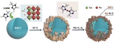
A schematic diagram illustrates the synthesis of CoFe nanoalloy-decorated BSCF based on the organic ligand-assisted in situ exsolution method. For the synthesis, the BSCF perovskite sample was first prepared via a sol–gel method. Then, 2-MIM organic ligand was introduced as a mild reducing agent. 2-MIM may induce the etching of surface cobalt of BSCF and coordinate to form a ZIF-67-like material at room temperature, as demonstrated by FTIR (Fig. S1†). The surface ZIF-67 modified BSCF was then filtered from the suspension and calcined at 750 °C in a N2 atmosphere. During the calcination, ZIF-67 was pyrolyzed with the formation of Co–N–C, while the reducing atmosphere created during the pyrolysis induced the co-exsolution of partial Co and Fe from the perovskite lattice with the formation of CoFe nanoalloys, which together with Co–N–C co-decorated over the BSCF surface.A schematic illustration of in situ CoFe exsolution over the surface of BSCF perovskite via organic ligand reduction followed by thermal treatment in a N2 atmosphere.
 | (4) |
 | (5) |
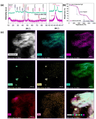
To confirm the effectiveness of our strategy for the synthesis of CoFe nanoalloy modified BSCF, three precursors with different BSCF to 2-MIM ratios, i.e., CoFe–Co–N–C–Bx (x = 1, 2, 3), and reference ZIF-67 catalysts were investigated by ex situ XRD with the patterns as shown in Fig. 1a and S2.† The main diffraction peaks of the three CoFe–Co–N–C–Bx samples matched well with that of phase-pure BSCF (Fig. S3†). It suggests that the main perovskite of BSCF was successfully maintained after the calcination in a nitrogen atmosphere for the precursors. From a careful observation of the XRD patterns, it was found that there were four crystalline phases inside the samples: (i) the main BSCF-related perovskite phase; (ii) graphitic carbon as shown by the characteristic peaks at 2θ = 26 and 43°, corresponding to the (002) and (100) planes of sp2 carbon and sp3 carbon; (iii) metallic Co species, as evident by the intense diffraction peaks at 2θ = 44.1, 52.0 and 75.7°, corresponding well to (111), (200), and (220) reflections, and (iv) FeCo alloys, by observing characteristic peaks as manifested by 2θ = 44.8, 65.3 and 82.7°, matching the (110), (200) and (211) crystal facets. It is well known that cobalt species can promote the graphitization of carbon during pyrolysis. Thus the formation of graphitic carbon was likely catalysed by the exsolved metallic species at high temperature.32
To observe the phase transformation during the calcination, the thermal decomposition behaviour of the precursor was analyzed by TGA in a nitrogen atmosphere (Fig. 1b and S4†). From Fig. 1b in combination with XRD and XPS (will be discussed later), the decomposition process can be well separated into three main stages: (i) evaporation of adsorbed water (<100 °C); (ii) decomposition of the metal organic framework (Co–N–C), which happened at 300–450 °C, and (iii) the loss of lattice oxygen as a result of in situ exsolution of the CoFe alloy after the reduction of oxides of Co and Fe at high temperature (700–900 °C). It could be figured out that the 2-MIM organic ligand facilitated the reduction of the perovskite accompanied the generation of oxygen vacancies. Subsequently, cobalt species co-ordinated with 2-MIM with the generation of B-site cation defects and oxygen vacancies. In turn, the segregation energy of Fe exsolution significantly reduced, leading to the exsolution of CoFe alloy nanoparticles followed by the thermal treatment. Furthermore, N-doped carbon also contributed to exposing the maximum BSCF perovskite active sites as demonstrated by the high surface area (Table S1 and Fig. S5†).
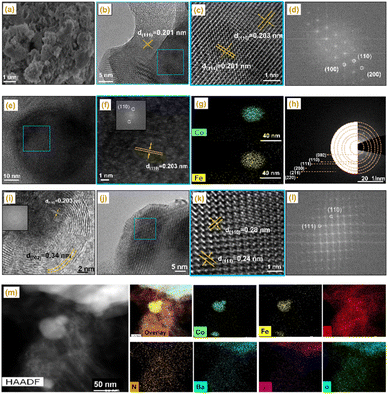
To get more structural and compositional information, atomic-scale high angle annular dark-field (HAADF) and energy-dispersive X-ray spectroscopy (EDS) chemical mapping experiments were conducted, which conspicuously display the selective metal exsolution and phase segregation of BSCF. Fig. 1c demonstrates the uniform distribution of Ba, Sr and O inside the sample. As a whole, Co and Fe were evenly distributed; however, some metallic Co/Fe islands on the sample surface were also observed, indicating the metal exsolution and CoFe alloy segregation. In combination with the HAADF (Fig. S6† and 2m) and XRD results, it can be inferred that Co/Fe co-exsolution was indeed eventuated, leading to the formation of a CoFe alloy phase. In turn, the CoFe alloy nanoparticles were immobilized by the porous carbon network. After the pyrolysis, Co–N–C and CoFe–N–C networks were generated, together with BSCF. The intimate connection between BSCF and other metallic species and N-doped graphitic carbon will expedite the electronic movement, which benefits the oxygen electrocatalysis.
To gain further insight into the crystal evolution of the CoFe–Co–N–C–B2 catalyst on an atomic scale, high-resolution TEM observation was conducted with the results shown in Fig. 2 and S6.†Fig. 2b and c depict the lattice spacings of 0.201 and 0.203 nm, which are consistent with the diffraction planes (111) and (110) of the Co metallic species and CoFe alloy, as confirmed by XRD. Moreover, the corresponding fast Fourier transformed (FFT) images are also in good agreement with the lattice spacing. Another lattice fringe of 0.203 nm, representing the dark core in Fig. 2e, could again be attributed to the (1 1 0) facet of the CoFe alloy, as confirmed by EDS mapping (Fig. 2e–g). Fig. 2h displays selected area electron diffraction (SAED) and represents the diffraction of the (110), (111) (200), (211), and (220) planes of metallic Co, CoFe alloy, BSCF and graphitic carbon. The high-resolution TEM image also reveals the dark cores in Fig. 2i and S7,† corresponding to the CoFe alloy and metallic Co nanoparticles, which were encapsulated by carbon shells. The interplanar spacing of the outer shell was found to be 0.34 nm, attributed to the (002) plane of graphitic carbon. It is noticeable that Co nanoparticles were entirely encapsulated by graphitic carbon layers, providing total adhesion and protecting them against dissolution.33,34 In addition, the lattice fringes with interplanar spacings of 0.24 and 0.28 nm were also observed, ascribed to the BSCF perovskite, matching well with the corresponding FFT patterns (Fig. 2j–l).35 According to Fig. 2j and S6,† such BSCF particles were also encapsulated by the carbon layers.
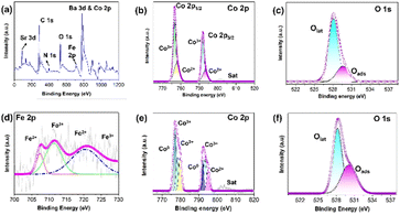
It is recognized that the activity of a catalyst is closely related to its electronic structure. The elemental composition and electronic structure of the samples were scrutinized by X-ray photoelectron spectroscopy (XPS). The XPS survey scan of the CoFe–Co–N–C–B2 sample showed the concomitance of Ba, Co, Fe, Sr, C and N elements, which composed the whole catalytic system. The high-resolution XPS spectrum of Co 2p demonstrates two major doublets namely Co 2p3/2 and Co 2p1/2, as shown in Fig. 3b and e. Clearly, Co 2p deconvoluted into two peaks namely Co2+ and Co3+ in BSCF, while CoFe–Co–N–C–B2 deconvoluted into three peaks Co0, Co2+ and Co3+.
In a similar fashion, the XPS high resolution spectrum of Fe 2p may be deconvoluted into Fe0 (707.5 and 719.11 eV), Fe2+ (710.9 and 720.1 eV), and Fe3+ (713.3 and 724.0 eV) spectra. The concomitance of Co0 and Fe0 further suggests the formation of CoFe alloys.36,37
The oxidation states of O 1s of pristine BSCF (Fig. 3c) and CoFe–Co–N–C–B (Fig. 3f) were also investigated by XPS. Two types of oxygen species were observed: oxygen species adsorbed on the surfaces of BSCF perovskite oxide and the lattice oxygen species in the perovskite crystals. The higher binding energy of CoFe–Co–N–C–B2 in contrast to pristine BSCF indicates the increased amount of oxygen vacancies, which are beneficial for oxygen electrocatalysis.
It is well known that the catalytic activity of carbon materials could be well tuned via heteroatom doping such as N, B or S.38 The different electronic structure and coordination environment of the dopant may significantly affect the catalytic activity of the surrounding carbon atoms. It was found that for the N 1s peak, it may be deconvoluted into four prominent peaks at 397.9, 398.9, 400.1, 401.1 and 403.2 eV, which are attributed to pyridinic N, Co–N bond, pyrrolic N, graphitic N and oxidized N species, respectively (Fig. S8a†). Higher proportions of pyrrolic and pyridinic N species are considered beneficial to promote OER and ORR electrocatalysis because of their strong interaction with oxygen reaction intermediates.39 Moreover, pyrrolic and pyridinic N moieties are capable of suppressing the energy barrier for oxygen adsorption and enhancing the ORR catalysis.40,41 In addition, pyridinic and graphitic N were reported to improve the limiting current density and to reduce the onset potential for the ORR.42 It was believed that the N heteroatom doped into the carbon lattice induces charge delocalization in the π conjugation due to electronegativity differences causing an uneven charge distribution in the neighbouring carbon atoms.43 As a result, the density of free charge carriers increases to boost the adsorption and reduction of oxygen, thereby facilitating ORR activity. Meanwhile, the peak at 285.7 eV, representing C–N, was observed for both Co–C–N and CoFe–Co–N–C–B2 catalysts in the C 1s spectrum (Fig. S8b and c†).
Electrocatalytic performance
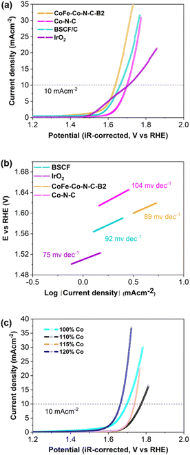
The electrocatalytic performance of the samples was first evaluated using three-electrode cells. Fig. 4a and S9† illustrate the current density vs. iR-corrected polarization curves of CoFe–Co–N–C-Bx (x = 1, 2, 3) and Co–N–C, with BSCF and IrO2 as reference catalysts. The potential at which the anodic peak reaches the value of 10 mA cm−2 was used as an OER activity descriptor. It is obvious that CoFe–Co–N–C–B2 exhibited the highest OER activity, even superior to that of BSCF. Interestingly, CoFe–Co–N–C–B2 also exhibited a lower onset potential (∼1.405 V at 0.05 mA cm−2) for the OER. This may be attributed to the pre-oxidation of Co2+ to Co3+ (CoOOH). It is noticeable that Co–N–C also demonstrated reasonable OER activity, which implies that exsolved Co metallic species and CoFe embedded in N-doped carbon also contributed to augment the OER activity of CoFe–Co–N–C–B2 coupled with BSCF. The corresponding Tafel slopes, computed from the OER curves, represent the reaction kinetics (Fig. 4b and S10†). The variation in Tafel slopes implies that each catalyst possibly follows a different OER mechanistic pathway. The lower value of the Tafel slope of CoFe–Co–N–C–B2 symbolizes the superior OER kinetics because it is capable of delivering sufficient current with a modest increase in overpotential.44 Consequently, it is anticipated that the activation barrier for the OER will be sufficiently dropped.To investigate the influence of exsolved cobalt metallic species on OER catalysis, 2MIM was incorporated with different loadings of cobalt and compared with ZIF-67 derived Co–N–C (100% Co). Initially, when the loading of Co was increased, it delivered a current density of j = 10 mA cm−2 at high overpotential and subsequently OER performance increased at high loading (Fig. 4c). So, the exsolved cobalt metal displayed a strong influence on the OER activity. The abrupt decline in the OER activity of CoFe–Co–N–C–B1 and CoFe–Co–N–C–B3 could be associated with the lower/higher exsolution of Co metal, respectively (Fig. S9†). It implies that BSCF also provided an opportunity to tailor the Co loading in the 2-MIM organic linker. Consequently, it can be inferred that Co–N–C metal and the encapsulation of CoFe alloys into the N-doped porous network, coupled with BSCF, have achieved desirable outcomes in terms of enhancing the OER catalysis.
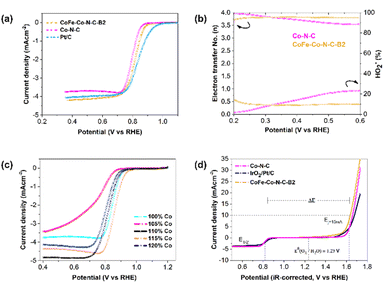
The ORR performance was also studied using the same technique, and evaluated based on the onset potential, half-wave potential and limiting current density. It was interesting to notice that the onset potential and half-wave potentials of CoFe–Co–N–C–B2 and Co–N–C are exactly comparable (Fig. 5a). Furthermore, the limiting current density of CoFe–Co–N–C–B2 in contrast with that of Co–N–C and commercial Pt/C increased by 16% and 5%, respectively. The increment in the limiting current density of CoFe–Co–N–C–B2, as compared to that of Co–N–C, may be attributed to the additional benefit provided by the CoFe alloy embedded in the N-doped carbon network, coupled with Co–N–C moieties. Moreover, the presence of N also caused a favourable impact because it induced positive charges on the adjoining carbon atoms as a result of the higher electronegativity of N, which in turn reduced the adsorption barrier for oxygen molecules.45,46 Similar to the OER, the influence of exsolved Co metal was also evaluated for ORR performance (Fig. 5c). It followed a comparable trend as that of the OER and justifies the sudden drop in the ORR activity of CoFe–Co–N–C–B1 and CoFe–Co–N–C–B3 with the same reason (Fig. S11†). Thus, it may be inferred that the exsolved Co metal loading had substantially contributed to the ORR.
The ORR mechanism was further studied based on the rotating ring-disk electrode (RRDE) as shown in Fig. 5b. It was found that the number of transferred electrons for CoFe–Co–N–C–B2 is about 3.83. This points out that the reaction pathway for CoFe–Co–N–C–B2 was dominated by a quasi-four electron transfer pathway. The four-electron pathway is preferable because it catalyses the ORR through 4e−, leading to the complete reduction of O2. However, in the case of Co–N–C, the number of transferred electrons started to drop with the growth in potential until it reached 3.5 electrons. The selectivity of the CoFe–Co–N–C–B2 catalyst towards the ORR was further appraised by detecting the peroxide (HO2−) intermediate yield. It is interesting to notice that the CoFe–Co–N–C–B2 catalyst experienced very low peroxide yield (10%) and remained constant throughout the potential range. On the other hand, the Co–N–C catalyst, which is recognized as an outstanding ORR catalyst, produced a large peroxide yield. As the potential increased so did the peroxide yield, which reached a value as high as 23% for the Co–N–C catalyst. Therefore, the FeCo–N–C–B2 catalyst is more effective at overcoming the energy barrier for O–O bond breaking than Co–N–C, enhancing the ORR catalysis.47,48 In turn, the amount of H2O2 generation was sufficiently reduced as witnessed in the case of FeCo–N–C containing BSCF. Meanwhile, the pristine perovskite BSCF proceeded through varying the electron transfer number and peroxide yield, indicating different pathways followed by pristine BSCF, making them infeasible for ORR catalysis (Fig. S12†). These findings are consistent with the results of the RDE. Therefore, it is likely that the exsolved Co and CoFe species from the BSCF lattice and those embedded in N-doped carbon conspicuously contributed to the enhanced ORR activity. Consequently, CoFe–Co–N–C–B2 turned out to be an excellent bi-functional (OER as well as ORR) catalyst.
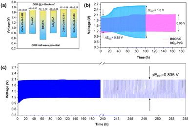
To confirm the superior bi-functionality of CoFe–Co–N–C–B2, it was comparatively studied with Co–N–C and IrO2–Pt/C using bi-functional activity metrics, i.e., the potential gap (ΔE), obtained by the variance (ΔE = Ej=10 − E1/2) of Ej=10, the potential at a current density of j = 10 mA cm−2 and E1/2, the half-wave potential in the whole region of the OER and ORR respectively. It can be observed that the CoFe–Co–N–C–B2 catalyst exhibited the lowest potential gap of 0.82 V (Fig. 5d). The lowest potential gap obtained by the CoFe–Co–N–C–B2 catalyst also manifests its superior bi-functional (OER/ORR) oxygen electrocatalysis. In contrast, the bi-functional activity of the IrO2–Pt/C catalyst was not up to the mark (Fig. 6a). When the comparative analysis of the bi-functional activities of all the prepared catalysts and the reference catalysts was conducted, CoFe–Co–N–C–B2 was found to be the optimal catalyst, exhibiting the lowest potential gap; therefore it may be employed for the reversible oxygen reactions.
Zn-air battery performance
As the optimal catalyst CoFe–Co–N–C–B2 conforms to the prerequisites (high electronic conductivity, high surface area, excellent bi-functional (OER/ORR) oxygen catalysis, and porous network) of an efficient oxygen electrocatalyst, which qualifies it to serve as an air electrode for ZABs. Therefore, as a proof of concept, we deployed CoFe–Co–N–C–B2, BSCF and IrO2–Pt/C as air electrodes for rechargeable ZABs to investigate their rechargeability and cycling stability. It can be observed that the CoFe–Co–N–C–B2 integrated ZAB delivered a relatively smaller discharge and charge voltage gap (ΔEDC) of 0.835 V, indicating the superior recharge ability of the optimal catalyst (Fig. 6c). The CoFe–Co–N–C–B2 assembled battery displayed a long-term stability over a period of more than 250 h without an obvious increase in the potential gap. On the other hand, the potential gap in the IrO2–Pt/C assembled ZAB lifted rapidly, which could be caused by the escalated polarization (Fig. 6b). Although the discharge/charge voltage gap was about 0.85 V initially, it increased to a higher value of ΔEDC = 1.8 V within 100 h, which makes them infeasible for commercialization. Likewise, pristine BSCF exhibited excellent OER activity, whereas inferior ORR activity. Eventually, the performance of the pristine BSCF integrated ZAB gradually deteriorated and led to a relatively higher voltage gap of ΔEDC = 0.96 V, which may be associated with the leaching and metal exsolution.49 In contrast, Co and CoFe exsolved metals from the BSFC lattice, integrated into an N-doped porous carbon network (CoFe–Co–N–C–B2) have demonstrated significant potential in attaining the excellent bi-functional activity and superior cycling stability. Consequently, this may be employed as an efficient and cost-effective air electrode for zinc-air batteries.Using density functional theory (DFT) calculations and UV laser enhanced photoemission electron microscopy experiments, Deng and co-researchers have established that metal@N-doped carbon possessed the most negative adsorption free energy (metal@N-doped carbon < metal@ carbon < carbon).50 Thus, oxygen is likely to adsorb readily on Co and/or Fe @N-doped carbon, as an outcome of elevated charge transfer from carbon to oxygen, promoting covalent as well as electrostatic bonding between them. As a result, O2 is adsorbed, activated and reduced on these sites. Also, a great deal of evidence has established that Co–N–C is capable of suppressing the binding energies of *OH and *OOH species adsorbed on the surface and improving the ORR electrocatalytic performance.51,52
On the other hand, the CoFe alloy modulated the encapsulated carbon surface by fine-tuning the electronic configuration of adjacent carbon atoms. Actually, when the CoFe alloy was encapsulated by the N-doped carbon, CoFe experienced a deficiency of electrons as an outcome of the transfer of electrons and induced an increase in electron density on the carbon surface, increasing the Fermi level. Moreover, the presence of N heteroatoms in the carbon lattice further reduces its local work function and promotes the electrocatalytic activity on the carbon surface.53,54 Thus, in the course of electrocatalytic reduction, the carbon surface was activated and supplemented by the excess electrons, delivered from the FeCo alloy.
The graphitic shell supplemented with a plethora of electrons is also conducive for the 4e− pathway.55,56 The 4e− pathway is considered more favourable for ORR catalysis because it leads to the complete reduction of O2 to OH− with minimum/no generation of peroxide (HO2−) intermediates. Thus, the CoFe alloy promoted the ORR selectivity towards the 4e− path-way and promoted the electronic conductivity. Interestingly, the positively charged CoFe alloy was also conducive for promoting the OER activity by absorbing OH− or H2O through electrostatic forces, triggering the electron transfer between CoFe and O22− and O2− reaction intermediates.57 Eventually, N-doped carbon and B-site metal sites (Co/Fe) developed a symbiotic effect and led to the ORR activity, which is in agreement with several research findings.58–61 Therefore, this reaction emerged as a pseudo 4e− pathway on the RRDE. On the other hand, BSCF/CoFe and oxygen vacancies together presented the OER activity. The particular steps describing the OER as well as the ORR mechanisms are displayed in Fig. 7 and S13.† Thus, the heterostructures consisting of different materials coupled at the interface brought about unique functionalities stemming from the tuning of the local electronic structure leading to superior oxygen reaction kinetics.
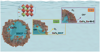 | ||
| Fig. 7 Possible mechanisms for the OER as well as ORR for CoFe nanoalloys exsolved over the surface of BSCF and Co–N–C. | ||
Conclusions
In summary, we have devised a novel strategy for the in situ exsolution of CoFe alloys over the surface of BSCF perovskite using a 2-MIM organic ligand as a gentle reducing agent. Cobalt species over the perovskite surface co-ordinated with 2-MIM produce metal organic framework, ZIF-67. Upon heat treatment in a N2 atmosphere, CoFe nanoalloys were in situ exsolved from the BSCF lattice surface and ZIF-67 was transformed into Co–N–C. Consequently, the BSCF–CoFe interface, newly generated oxygen vacancies and Co–N–C porous networks provided conduction pathways for oxygen ions and electrons, leading to enhanced electrochemical bi-functional (OER/ORR) performance. BSCF/CoFe presented the OER activity, while Co–N–C and CoFe contributed to the ORR activity. The exsolved Co metal induced a higher degree of graphitization to carbon, which in turn provided high electronic conductivity even without the addition of conductive carbon. Moreover, Ba2+ and Sr2+ ions also contributed to enhance the OH− ion adsorption capacity, leading to enhanced OER activity. CoFe alloy decorated BSCF suppressed the peroxide yield by 15% in comparison with the Co–N–C catalyst, thereby contributing to promote the ORR selectivity. Consequently, the obtained catalyst presented impressive bi-functional activity, producing a potential gap of 0.835 V and tangible high cycling stability over a period of more than 250 h for zinc-air batteries.Author contributions
All the authors contributed to the material design, data interpretation and paper revision.Conflicts of interest
There are no conflicts to declare.Acknowledgements
The authors would like to acknowledge the financial support from the Australian Research Council discovery projects via grant nos DP200103332, DP200103315 and DP220103669. The authors also would like to acknowledge the support provided by the “Commonwealth Australian Government Research Training Program (RTP) Scholarship” at Curtin University, Perth, Australia.References
- A. S. Al-Fatesh, Y. Arafat, S. O. Kasim, A. A. Ibrahim, A. E. Abasaeed and A. H. Fakeeha, Appl. Catal., B, 2021, 280, 119445 CrossRef CAS.
- L. Liu, H. Guo, L. Fu, S. Chou, S. Thiele, Y. Wu and J. Wang, Small, 2021, 17, 1903854 CrossRef CAS PubMed.
- J.-N. Liu, C.-X. Zhao, J. Wang, D. Ren, B.-Q. Li and Q. Zhang, Energy Environ. Sci., 2022, 15, 4542–4553 RSC.
- Z. Khan, M. Vagin and X. Crispin, Adv. Sci., 2020, 7, 1902866 CrossRef CAS.
- J. Li, Y. Kang, W. Wei, X. Li, Z. Lei and P. Liu, Chem. Eng. J., 2021, 407, 127961 CrossRef CAS.
- F. Dong, L. Li, Z. Kong, X. Xu, Y. Zhang, Z. Gao, B. Dongyang, M. Ni, Q. Liu and Z. Lin, Small, 2021, 17, 2006638 CrossRef CAS.
- K. Tang, H. Hu, Y. Xiong, L. Chen, J. Zhang, C. Yuan and M. Wu, Angew. Chem., Int. Ed., 2022, 61, 202202671 Search PubMed.
- M. Luo, W. Sun, B. B. Xu, H. Pan and Y. Jiang, Adv. Energy Mater., 2021, 11, 2002762 CrossRef CAS.
- K. Tang, C. Yuan, Y. Xiong, H. Hu and M. Wu, Appl. Catal., B, 2020, 260, 118209 CrossRef CAS.
- T. Zhou, N. Zhang, C. Wu and Y. Xie, Energy Environ. Sci., 2020, 13, 1132–1153 RSC.
- X. Xu, Y. Pan, Y. Zhong, C. Shi, D. Guan, L. Ge, Z. Hu, Y.-Y. Chin, H.-J. Lin, C.-T. Chen, H. Wang, S. P. Jiang and Z. Shao, Adv. Sci., 2022, 9, 2200530 CrossRef CAS PubMed.
- X. Xu, W. Wang, W. Zhou and Z. Shao, Small Methods, 2018, 2, 1800071 CrossRef.
- S. Park, D. Oh, J. Ahn, J. K. Kim, D.-H. Kim, S. Kim, C. Park, W. Jung and I.-D. Kim, Adv. Mater., 2022, 34, 2201109 CrossRef CAS PubMed.
- J. H. Kim, J. K. Kim, J. Liu, A. Curcio, J.-S. Jang, I.-D. Kim, F. Ciucci and W. Jung, ACS Nano, 2021, 15, 81–110 CrossRef CAS PubMed.
- J.-S. Jang, J. K. Kim, K. Kim, W.-G. Jung, C. Lim, S. Kim, D.-H. Kim, B.-J. Kim, J. W. Han, W. Jung and I.-D. Kim, Adv. Mater., 2020, 32, 2070342 CrossRef.
- T. Zhu, X. Chen, W. Ni, Q. Zhong and M. Han, Int. J. Hydrogen Energy, 2019, 44, 31386–31393 CrossRef CAS.
- R. Glaser, T. Zhu, H. Troiani, A. Caneiro, L. Mogni and S. Barnett, J. Mater. Chem. A, 2018, 6, 5193–5201 RSC.
- H. Lv, L. Lin, X. Zhang, Y. Song, H. Matsumoto, C. Zeng, N. Ta, W. Liu, D. Gao, G. Wang and X. Bao, Adv. Mater., 2020, 32, 1906193 CrossRef CAS.
- H. Lv, T. Liu, X. Zhang, Y. Song, H. Matsumoto, N. Ta, C. Zeng, G. Wang and X. Bao, Angew. Chem., Int. Ed., 2020, 59, 15968–15973 CrossRef CAS PubMed.
- J. T. S. Irvine, D. Neagu, M. C. Verbraeken, C. Chatzichristodoulou, C. Graves and M. B. Mogensen, Nat. Energy, 2016, 1, 15014 CrossRef CAS.
- F. Guan, X. Zhang, Y. Song, Y. Zhou, G. Wang and X. Bao, Chin. J. Catal., 2018, 39, 1484–1492 CrossRef CAS.
- M. Kim, B. Lee, H. Ju, S. W. Lee and J. Kim, Adv. Mater., 2019, 31, 1901977 CrossRef PubMed.
- Y. Jiang, Z. Geng, Y. Sun, X. Wang, K. Huang, Y. Cong, F. Shi, Y. Wang, W. Zhang and S. Feng, ACS Sustainable Chem. Eng., 2020, 8, 302–310 CrossRef CAS.
- L. Yu, H. Zhou, J. Sun, F. Qin, D. Luo, L. Xie, F. Yu, J. Bao, Y. Li, Y. Yu, S. Chen and Z. Ren, Nano Energy, 2017, 41, 327–336 CrossRef CAS.
- C. Lv, B. Liang, K. Li, Y. Zhao and H. Sun, Biosens. Bioelectron., 2018, 117, 802–809 CrossRef CAS PubMed.
- S. Kim, J.-W. Jung, D. Song, S.-H. Cho, J. Kim, J. K. Kim, D. Oh, H. Sun, E. Cho, I.-D. Kim and W. Jung, Appl. Catal., B, 2022, 315, 121553 CrossRef CAS.
- O. Kwon, S. Sengodan, K. Kim, G. Kim, H. Y. Jeong, J. Shin, Y.-W. Ju, J. W. Han and G. Kim, Nat. Commun., 2017, 8, 15967 CrossRef CAS PubMed.
- S. Joo, O. Kwon, K. Kim, S. Kim, H. Kim, J. Shin, H. Y. Jeong, S. Sengodan, J. W. Han and G. Kim, Nat. Commun., 2019, 10, 697 CrossRef CAS PubMed.
- S. Song, J. Zhou, X. Su, Y. Wang, J. Li, L. Zhang, G. Xiao, C. Guan, R. Liu, S. Chen, H.-J. Lin, S. Zhang and J.-Q. Wang, Energy Environ. Sci., 2018, 11, 2945–2953 RSC.
- X. Xu, C. Su and Z. Shao, Energy Fuels, 2021, 35, 13585–13609 CrossRef CAS.
- J. Shao, Z. Wan, H. Liu, H. Zheng, T. Gao, M. Shen, Q. Qu and H. Zheng, J. Mater. Chem. A, 2014, 2, 12194–12200 RSC.
- K. Strickland, E. Miner, Q. Jia, U. Tylus, N. Ramaswamy, W. Liang, M.-T. Sougrati, F. Jaouen and S. Mukerjee, Nat. Commun., 2015, 6, 7343 CrossRef CAS PubMed.
- G. Wu, A. Santandreu, W. Kellogg, S. Gupta, O. Ogoke, H. Zhang, H.-L. Wang and L. Dai, Nano Energy, 2016, 29, 83–110 CrossRef CAS.
- N. A. Galiote, F. E. R. Oliveira and F. H. B. Lima, Appl. Catal., B, 2019, 253, 300–308 CrossRef CAS.
- Y. Arafat, M. R. Azhar, Y. Zhong, X. Xu, M. O. Tadé and Z. Shao, Nano-Micro Lett., 2020, 12, 130 CrossRef CAS PubMed.
- S. Chang, H. Zhang and Z. Zhang, J. Energy Chem., 2021, 56, 64–71 CrossRef CAS.
- X. Liu, L. Wang, P. Yu, C. Tian, F. Sun, J. Ma, W. Li and H. Fu, Angew. Chem., Int. Ed., 2018, 57, 16166–16170 CrossRef CAS PubMed.
- Y. Arafat, M. R. Azhar, Y. Zhong, H. R. Abid, M. O. Tadé and Z. Shao, Adv. Energy Mater., 2021, 11, 2100514 CrossRef CAS.
- H. Hu, Y. Xie, F. M. D. Kazim, K. Qu, M. Li, Z. Xu and Z. Yang, Sustainable Energy Fuels, 2020, 4, 5188–5194 RSC.
- W. He, C. Jiang, J. Wang and L. Lu, Angew. Chem., Int. Ed., 2014, 53, 9503–9507 CrossRef CAS.
- H.-W. Liang, X. Zhuang, S. Brüller, X. Feng and K. Müllen, Nat. Commun., 2014, 5, 4973 CrossRef CAS.
- L. Lai, J. R. Potts, D. Zhan, L. Wang, C. K. Poh, C. Tang, H. Gong, Z. Shen, J. Lin and R. S. Ruoff, Energy Environ. Sci., 2012, 5, 7936–7942 RSC.
- Y. Wang, Y. Zhang, H. Huang and J. Qiao, ACS Sustainable Chem. Eng., 2019, 8, 731–738 CrossRef.
- Y. Pan, X. Xu, Y. Zhong, L. Ge, Y. Chen, J.-P. M. Veder, D. Guan, R. O'Hayre, M. Li, G. Wang, H. Wang, W. Zhou and Z. Shao, Nat. Commun., 2020, 11, 2002 CrossRef CAS.
- J. Di, J. Guo, N. Wang and G. Ma, ACS Sustainable Chem. Eng., 2019, 7, 7716–7727 CrossRef CAS.
- Y. Arafat, M. R. Azhar, Y. Zhong, M. O. Tadé and Z. Shao, Mater. Res. Bull., 2021, 140, 111315 CrossRef CAS.
- Z. Pei, H. Li, Y. Huang, Q. Xue, Y. Huang, M. Zhu, Z. Wang and C. Zhi, Energy Environ. Sci., 2017, 10, 742–749 RSC.
- A. Serov, M. H. Robson, M. Smolnik and P. Atanassov, Electrochim. Acta, 2012, 80, 213–218 CrossRef CAS.
- Y. Dai, J. Yu, C. Cheng, P. Tan and M. Ni, Chem. Eng. J., 2020, 125516 CrossRef CAS.
- D. Deng, L. Yu, X. Chen, G. Wang, L. Jin, X. Pan, J. Deng, G. Sun and X. Bao, Angew. Chem., Int. Ed., 2013, 52, 371–375 CrossRef CAS PubMed.
- L. Partanen, G. Murdachaew and K. Laasonen, J. Phys. Chem. C, 2018, 122, 12892–12899 CrossRef CAS.
- C. Li, M. Wu and R. Liu, Appl. Catal., B, 2019, 244, 150–158 CrossRef CAS.
- J. Deng, P. Ren, D. Deng and X. Bao, Angew. Chem., Int. Ed., 2015, 54, 2100–2104 CrossRef CAS.
- W. Niu and Y. Yang, ACS Appl. Energy Mater., 2018, 1, 2440–2445 CrossRef CAS.
- H.-S. Su, H.-S. Feng, Q.-Q. Zhao, X.-G. Zhang, J.-J. Sun, Y. He, S.-C. Huang, T.-X. Huang, J.-H. Zhong, D.-Y. Wu and B. Ren, J. Am. Chem. Soc., 2020, 142, 1341–1347 CrossRef CAS PubMed.
- F. Xiao, Z. Wang, J. Fan, T. Majima, H. Zhao and G. Zhao, Angew. Chem., Int. Ed., 2021, 60, 10375–10383 CrossRef CAS PubMed.
- J. Suntivich, K. J. May, H. A. Gasteiger, J. B. Goodenough and Y. Shao-Horn, Science, 2011, 334, 1383–1385 CrossRef CAS PubMed.
- V. Hermann, D. Dutriat, S. Müller and C. Comninellis, Electrochim. Acta, 2000, 46, 365–372 CrossRef CAS.
- X. Li, W. Qu, J. Zhang and H. Wang, J. Electrochem. Soc., 2011, 158, A597 CrossRef CAS.
- T. Poux, A. Bonnefont, A. Ryabova, G. Kéranguéven, G. Tsirlina and E. Savinova, Phys. Chem. Chem. Phys., 2014, 16, 13595–13600 RSC.
- C. E. Beall, E. Fabbri and T. J. Schmidt, ACS Catal., 2021, 11, 3094–3114 CrossRef CAS.
Footnote |
| † Electronic supplementary information (ESI) available. See DOI: https://doi.org/10.1039/d2ta07104e |
| This journal is © The Royal Society of Chemistry 2023 |

