 Open Access Article
Tuning the conductance of carbon rings with impurities and electric fields
Carlos Rojas *a,
A. Leónb,
M. Pacheco
 a,
Leonor Chico
 c and
P. A. Orellana
 a
a
aDepartamento de Física, Universidad Técnica Federico Santa María, Casilla 110 V, Valparaíso, Chile. E-mail: carlos.rojasle@usm.cl
bInstituto de Ciencias Básicas, Facultad de Ingeniería, Universidad Diego Portales, Avda. Ejército 441, Santiago, Chile
cGISC, Departamento de Física de Materiales, Facultad de Ciencias Físicas, Universidad Complutense de Madrid, 28040 Madrid, Spain
First published on 25th July 2023
Abstract
We explore two mechanisms to tune the electronic conductance of carbon atom rings, namely, substitutional impurities and in-plane external electric fields. First-principles calculations and a tight-binding approach are used to model the systems. Two bond configurations are studied, cumulenic and polyynic, which can be relevant depending on the number of carbon atoms in the ring. We find that both impurity substitution and electric field mechanisms allow for modifying the electronic spectrum and transport characteristics. Interestingly, cumulenic and polyynic carbon rings present a different response to these perturbations, which can also be a way to elucidate the bond nature of these structures.
1 Introduction
Single molecules are increasingly considered a potential building block in electronic devices, which holds great promise in miniaturization.1 Some successes have already been reported along this line, including molecules exhibiting significant on-off current ratios and large negative differential resistance in two-terminal transport, carbon nanotube bridges, and molecular rectifiers.2 Such setups can eventually be modeled by decomposing the system into coupled molecular subunits that collectively give rise to conducting quantum resonances and antiresonances. The properties of these features determine the transport properties of the system.By choosing organic molecules, this decomposition can extend device density beyond the limits of conventional small-scale silicon integrated circuits. In this context, carbon-based molecular junctions serve to study a wide variety of charge transport mechanisms since taking advantage of covalent C–C bonds avoids problems such as electromigration while presenting high-temperature stability.3 Ring-shaped carbon allotropes called cyclo[n]carbons (Cn) present this type of stable configuration of cumulenic, consecutive double bonds.4,5 In addition, there is a theoretical consensus that a polyynic configuration with alternating single and triple bonds could also represent the lowest energy geometry of these structures for n = 18.6–10 However, this configuration might be different for other numbers of carbon atoms.11 Due to their high reactivity, cyclo[n]carbons are mostly observed in the gas phase. However, the C18 molecule with a polyynic structure12 was recently synthesized on a surface and characterized with scanning probe microscopies, helping to clarify the controversy about the bond configuration of cyclo[n]carbons. Such breakthrough has also opened the possibility of studying cyclocarbons as possible building blocks in molecular junctions to create small-scale electronic devices. In fact, O-shaped structures as quantum rings have been assembled on semiconductor surfaces.13 If coherence of the wavefunction is maintained in these structures, quantum transport phenomena as for example persistent currents14,15 and the Aharonov–Bohm effect16–18 can be observed in the nanoscale.19
Controlling the dimensions, shape, and size of these systems is fundamental and of great technological importance because these parameters are strongly linked to their physical and chemical properties. Moreover, by intentionally doping the material we can modify its electronic, magnetic, and optical properties. It can also be a tool to tailor these devices based on carbon nanostructures.20 In this spirit, due to the scale of these structures, their manipulation by external means, such as electromagnetic fields, is key for nanotechnological applications. But, at the same time, they can also modify their properties.
A starting point to study this type of system is to connect a conventional conductor to a molecule or some molecular component to study their electron transport properties, as carried out in ref. 11. In this article, we study the electronic transport properties of a carbon atom ring coupled to a quantum wire and two electron reservoirs, considering the two possible bond configurations of cyclo[n]carbons. A thorough study of the ground state configuration, as performed in ref. 21 for isolated rings, is not pursued here. Rather, we focus on the differences produced by weak external perturbations such as adatoms in the ring and electric fields considering both bond configurations, cumulenic and polyynic. Previous studies of these coupled structures show that a single-electron model can explain several interesting transport properties, such as the appearance of antiresonances in the conduction spectrum.11,22–24 In addition, such simplification allows for obtaining analytical expressions for several relevant physical quantities, providing a better insight on the origin of the changes induced by the perturbations.
We focus on conductance changes due to an impurity in the ring and an external electric field, taking as a starting point the pristine conductor-lead structure. We show that the conductance presents an oscillating behavior with resonances and antiresonances with extra peaks due to the influence of these external agents, revealing the energy spectrum of the system. We employ a tight-binding (TB) model to derive our main results, along with first-principles calculations within the density functional theory (DFT) approximation to verify the validity of the single-electron model.
This article is organized as follows: In Sec. 2, we describe the system under consideration and the models used to calculate electronic and transport properties. The discussion of these quantities and comparisons with first-principles calculations are carried out in Sec. 3. Our results and conclusions are summarized in Sec. 4.
2 Geometry and models
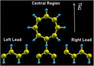
The system is schematically depicted in Fig. 1. The central region consists of a ring of M atomic sites and a homogeneous wire of N atomic sites, representing an arrangement of carbon atoms. The ring is attached to a site j in the wire. This central region is connected to two metallic leads modeled as two reservoirs of free states, and an external electric field is applied perpendicular to the wire within the plane of the molecule. A small electric field perpendicular to the plane of the structure would produce a rigid shift of the electronic spectrum, so we focus on a nontrivial configuration that modifies the energy levels of the system and its conductance.The Hamiltonian of the system within the tight-binding approximation is
| H = Hw + Hr + Hwr + HLR | (1) |
 | (2) |
The Hamiltonian for the isolated ring Hr reads
 | (3) |
 . The cumulenic geometry of the ring is modeled by setting v1 = v2, whereas for the polyynic configuration v1 and v2 have different values. The term in the Hamiltonian that describes the coupling between the wire and the ring is
| Hwr = −V(c†jd1 + d†1cj), | (4) |
 | (5) |
 | (6) |
 (fkq) represents the creation (annihilation) operator of an electron in the continuum with wavevector kq; the couplings between leads and system are given by the parameters
  with q = L, R.
We study the electronic transport properties in the framework of the Landauer approximation, where the two-terminal conductance G at zero temperature is proportional to the total transmission at the Fermi energy EF,
 | (7) |
The total transmission is obtained from the Green's functions of each isolated system via the Fisher–Lee relation, as detailed in ref. 11.
Lastly, the density of states (DOS) of the ring is also calculated to grasp a better understanding of the transport properties of the system, which is formulated in terms of Green's functions.
 | (8) |
First-principles calculations were also performed using DFT theory employing the GGA-PBE functional as well as transport calculations as implemented in OpenMX.25,26 We consider this approach to describe correctly the transport properties of our system; indeed, when considering the electron density gradient it takes into account in a precise way the effects of the non-local electron density of the system, which is very important when studying the formation of orbitals in the presence of π bonds. In fact, a previous study shows that this functional has excellent results when describing the transport properties of other carbon-based structures such as carbon nanoribbons, provided that they are not charged, as in this work.27 Notwithstanding, in order to find the ground state properties of the isolated rings, more sophisticated approaches have been recently used,21 studying in detail the relative energy between the cumulenic and polyynic forms of C4k+2 with k = 4–7 rings found with different calculations methods. We choose not to delve in the precise determination of the stability issues of our more complex leads-ring structure, and focus instead on the differences that both configurations may show in the conductance properties. We have used pseudoatomic orbitals (PAOs) as basis functions to extend the Kohn–Sham wavefunction of a particle. The Kohn–Sham equation is solved in order to obtain the electron density using the fictitious charge density formalism. The minimum energy configuration is found taking energy reorganization into account, by including structural relaxation and polarization effects in the calculation. We have treated the core Coulomb potential with the scheme of pseudopotentials proposed by Morrison, Bylander, and Kleinman.28 The cutoff energy in all our calculations is 150 Ry with a convergence criterion of 10−8 hartree. Furthermore, in all calculations of electrical transport, the method of non-equilibrium Green's function (NEGF) was used.26
3 Results and discussion
First of all, for simplicity, we have limited the number of atoms in the chain that connects the ring to the leads, setting N = 3. More sites in the chain generate a conduction spectrum with a greater number of resonances, as indicated in,11 which could hinder the analysis of the effects caused by the ring.Once we obtain the Green's functions, we calculate the conductance as a function of the energy levels of the wire and the carbon ring. Our previous work11 showed that the conductance presents an oscillating pattern of resonances and antiresonances; their positions correspond precisely to the energy spectrum of the wire and ring, respectively. Therefore, we can focus on smaller systems (both, coupling chain and carbon ring) in order to study the modifications produced by the external perturbations. We consider different ring sizes, ranging from M = 4 to M = 16. As commented above, larger rings introduce more features in the spectrum, but the conclusions regarding its origin and modification by external agents remain the same. Likewise, the connection of the ring on the wire has been set to j = 2, being a symmetrical point between the contacts. We have verified that in pristine rings changes in the position of the contact merely produce a shift in the energy of the conductance features, leaving our conclusions regarding the transport properties unaltered.
3.1 Impurity effects: cumulenic geometry
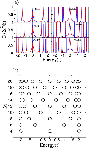
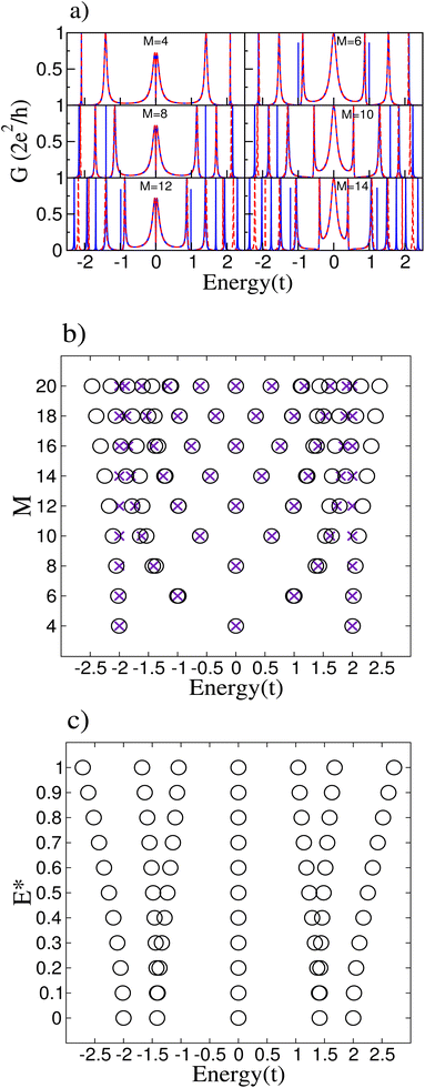
The cumulenic structure is modeled by setting all the hopping parameters of the ring equal to t; the impurity is treated as an atom with different onsite energy at an arbitrary position in the ring. We choose a small parameter with respect to the pristine system so perturbation theory is valid. Such weak modification may be due to an adatom on top of the carbon atom of the ring. We have verified that the results do not depend on the particular position of the impurity in the ring. We focus on the study of even rings since Cn molecules with n = 4k + 2 (k integer) are predicted to have higher stability.29–31Fig. 2(a) presents the results for the conductance of the system connected to the central atom of the conducting wire for different number atomic sites of the ring M. The system exhibits a series of resonances and antiresonances. The antiresonances that appear at the Fermi level for rings with size M = 4m (with m integer) are related to the spectra of the carbon rings.11 Furthermore, a resonant peak appears at the Fermi level for M = 4m and additional peaks at some energies where the conductance without the impurity is zero. To analyze the conductance, the energy spectra of the rings derived from the tight-binding model are presented in Fig. 2(b).
The main effect of the impurity is that it breaks the degeneracy of the ring states, justifying the appearance of new resonant peaks in the conductance not only at the Fermi level but at other energies for which degeneracies exist. For instance, there is only one extra peak at the Fermi energy for the ring with M = 4, whereas for M = 8 there are extra peaks near ε = −1.5t and ε = 1.5t. Obviously, the larger the ring, the more extra peaks may appear, as can be seen in Fig. 2(a).
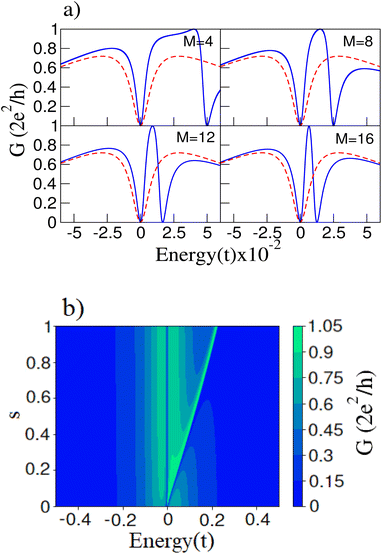
Fig. 3(a) displays the conductance zoomed near the Fermi energy for the rings with M = 4, 8, 12 and 16 sites with a small impurity. We can see that there are two antiresonances, one exactly at zero and another one shifted to positive energies an amount that depends on the size of the ring M. The pristine ring had two degenerate states at the Fermi level, i.e., at zero energy; the introduction of the impurity breaks this degeneracy. These two states result in two antiresonances in the conductance spectrum at their exact energies. We can predict the energy difference between these two states via degenerate perturbation theory. The diagonalization of the perturbation matrix related to the perturbative Hamiltonian Ĥp = s|1〉〈1| is given by
where the matrix elements Ĥpα,β = 〈ϕnα|Ĥp|ϕnβ〉 being |ϕnα〉 = M−1/2exp(i2πn/M) the different eigenstates that correspond to the same energy εn with α, β = m, 3m. The energy corrections for the eigenstates near the Fermi level are εn(1) = 0 and εn(1) = s/2m. Notice that these energy corrections not only depend on the number of atomic sites but also on the impurity onsite energy s. Obviously, increasing s will also increase the energy splitting of the two states near the Fermi energy, as it is shown in Fig. 3(b). Likewise, weaker impurities produce smaller changes; the differences for couplings smaller than s = 0.1t, such as s = 0.01t and s = 0.001t, only lie in the fact that the effects are more noticeable for larger values of the site energy s.
3.2 Impurity effects: polyynic geometry
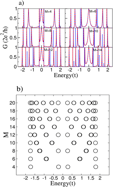
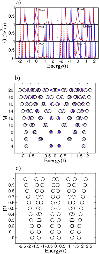
The polyynic geometry, with an alternating bond configuration, is modeled by the parameters vr = v1, v2, where v1 = t and v2 = 0.75 t. Results for the conductance of the system are shown in Fig. 4(a).In the cumulenic configuration, we observed that the introduction of an impurity removed the degeneracy of the ring states, leading to new resonant peaks in the conductance. We expect the same in the polyynic case, but now the antiresonance at the Fermi level for M = 4m disappears.11 For this configuration with the impurity, we notice additional resonant peaks in the conductance except for the ring with M = 4 sites, which has almost the same spectrum. It can be explained by examining the energy spectra of the isolated rings with the impurity, displayed in 4(b). All the pristine rings have degenerate states, which produce additional conductance resonances if an impurity breaks the degeneracies, except for the M = 4 ring. Its energy spectrum does not present degenerate states, leaving its conductance without additional peaks. Closely inspecting the pristine and impurity M = 4 ring conductances shows slight differences. Most importantly, it can be noticed a slight asymmetry in the conductance near the Fermi energy for the system with the impurity, related to the small changes in the energy spectrum.
3.3 Electric field effects: cumulenic geometry
It is straightforward to show that for the cumulenic configuration, the onsite energy dependence on the electric field E can be expressed as
 | (9) |
In order to explain the electric field results, Fig. 5(b) compares the energy spectra of the isolated rings with and without an electric field. It is clear that the states near the Fermi energy remain unchanged while the degeneracy of the states far from zero energy is broken. On the other hand, for rings with M = 4m with m integer, under an external electric field, a perturbative calculation confirms the invariance of the energy levels at the Fermi level. Following the procedure discussed in Subsection 3.1, it can be easily verified that the energy corrections are all equal to zero, taking into account that in this case, the perturbative Hamiltonian is given by  . Another relevant feature of the electric field on the ring is that the absolute value of the energies increases with the number M of atoms in the ring for those states far from the Fermi energy. Besides, the energy difference between the split states also increases with M. These trends, i.e., larger absolute values of the energies and larger splittings for degenerate levels, also hold for stronger electric fields, as shown in Fig. 5(c) for a M = 8 ring.
3.4 Electric field effects: polyynic geometry
For this case, the dependence of the site energy on the field goes as follows.
 | (10) |
 | (11) |
The increase in the absolute value of the energies is not so strong as for the cumulenic case, but the splitting in the degenerate states of this configuration is stronger than for the cumulenic case. Additionally, the energy difference between the states closest to the Fermi level for rings with a number of atoms M multiple of 4 diminishes as the size of the ring increases. The gap also widens when the magnitude of the external electric field increases, as shown in Fig. 6(c).
3.5 Comparison with DFT calculations
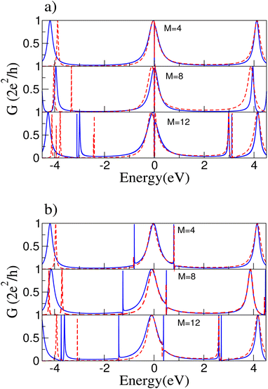
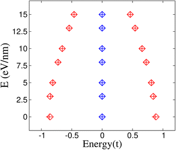
DFT calculations were performed to compare with the tight-binding model; we expect the comparison between the two approaches to be valid near the Fermi energy. Fig. 7 shows the conductance for both configurations, cumulenic (a) and polyynic (b), obtained with the two methods. This comparison correctly describes the antiresonance in the Fermi level for cumulenic rings and the new resonant peaks due to the splitting of the degenerate states near 3 eV for the ring with M = 12 sites for both ring configurations. The fit is very accurate for positive values of energy.Fig. 8 compares the energy spectra between TB and DFT for both ring configurations with M = 8, all for several values of the electric field strength. Again we find a good agreement near the Fermi energy since there are no changes in the states with zero energy in the cumulenic ring. In addition, notice that the energy difference between the states closest to the Fermi energy decreases as the electric field strength grows stronger for the polyynic configuration in the DFT calculation; both trends are also described correctly within the TB approach.
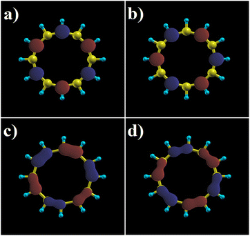
Lastly, Fig. 9 displays the orbitals for the HOMO and LUMO states for both ring configurations in order to compare with previous work,11 noting that there is a slight deformation of the orbitals in terms of symmetry when applying the electric field. It is also very remarkable that despite the fact that the energy spectrum of the states with zero energy is not perturbed, there is a change in the wavefunctions, which does reflect the presence of the electric field as an asymmetry in their shape, most clearly seen in Fig. 9(c) and (d). Obviously, one can obtain the eigenstates that match the shape of the orbitals via the diagonalization of the TB Hamiltonian with the presence of the electric field. Also, for weak electric fields, they can be written as a linear combination of the two degenerate states corresponding to the case without an electric field, as it can be graphically inferred by the appearance of the HOMO–LUMO states in Fig. 9.
4 Summary and conclusions
We have explored two ways of tuning the conductance and local density of states of a carbon ring connected to a carbon wire: by introducing an impurity or an external in-plane electric field perpendicular to the wire. We consider two bond configurations, cumulenic and polyynic. We found that the system exhibits an oscillating pattern of resonances and antiresonances related to the discrete spectra of the ring, modified by these external perturbations.Introducing an impurity atom in the carbon ring breaks the degeneracy of the states, producing new peaks in the conductance spectra for both the cumulenic and polyynic configurations. In the cumulenic case, an additional antiresonance arises near the Fermi energy due to the energy splitting of the degenerate states of the pristine carbon ring. This energy splitting shows a dependence on the onsite energy of the impurity s and the number of atomic sites of the ring M.
Concerning the application of an external electric field, the degeneracy of the states also breaks, although the behavior near the Fermi level remains unaltered in the cumulenic configuration. The energy difference of the states close to the Fermi level in the polyynic configuration decreases as the number of atomic sites in the ring M increases.
The effect is the electric field is more noticeable far from the Fermi energy, especially for larger M.
In summary, we have studied different mechanisms to modify the electronic and transport properties of systems composed of carbon atom rings with different sizes and bond configurations. The difference in their response to external perturbation can be a way to elucidate the nature of the bond in these intriguing systems.
Conflicts of interest
There are no conflicts to declare.Acknowledgements
This work has been partially supported by Universidad Santa María Grant USM-DGIIP PI-LI 1925 and 1919 and FONDECYT Grants 1201876 and 1211913, Spanish MCIN and AEI, and the European Union under Grant PID2019-106820RB-C21 (MCIN/AEI/FEDER, UE).Notes and references
- D. Xiang, X. Wang, C. Jia, T. Lee and X. Guo, Molecular-Scale Electronics: From Concept to Function, Chem. Rev., 2016, 116, 4318–4440 CrossRef CAS PubMed.
- R. Gupta, J. A. Fereiro, A. Bayat, A. Pritam, M. Zharnikov and P. C. Mondal, Nanoscale molecular rectifiers, Nat. Rev. Chem., 2023, 7, 106–122 CrossRef CAS.
- R. L. McCreery, Carbon-Based Molecular Junctions for Practical Molecular Electronics, Acc. Chem. Res., 2022, 55, 2766–2779 CrossRef CAS.
- V. Parasuk, J. Almlof and M. W. Feyereisen, J. Am. Chem. Soc., 1991, 113, 1049–1050 CrossRef CAS.
- C. Neiss, E. Trushin and A. Görling, The Nature of One-Dimensional Carbon: Polyynic versus Cumulenic, ChemPhysChem, 2014, 15, 2497–2502 CrossRef CAS PubMed.
- T. Torelli and L. Mitas, Electron correlation in C 4 n+ 2 carbon rings: aromatic versus dimerized structures, Phys. Rev. Lett., 2000, 85, 1702 CrossRef CAS PubMed.
- S. Arulmozhiraja and T. Ohno, CCSD calculations on C 14, C 18, and C 22 carbon clusters, J. Chem. Phys., 2008, 128, 114301 CrossRef PubMed.
- F. Diederich, Y. Rubin, C. B. Knobler, R. L. Whetten, K. E. Schriver, K. N. Houk and Y. Li, Science, 1989, 245, 1088–1090 CrossRef CAS PubMed.
- G. V. Baryshnikov, R. R. Valiev, A. V. Kuklin, D. Sundholm and H. Ågren, J. Phys. Chem. Lett., 2019, 10, 6701–6705 CrossRef CAS.
- A. J. Stasyuk, O. A. Stasyuk, M. Solà and A. A. Voityuk, Chem. Commun., 2020, 56, 352–355 RSC.
- C. Rojas, A. León, M. Pacheco, L. Chico and P. Orellana, Transport signatures of few-atom carbon rings, Phys. Chem. Chem. Phys., 2022, 24, 15973–15981 RSC.
- K. Kaiser, L. M. Scriven, F. Schulz, P. Gawel, L. Gross and H. L. Anderson, Science, 2019, 365, 1299–1301 CrossRef CAS.
- K. Kanisawa and S. Fölsch, et al., Quantum rings engineered by atom manipulation, Phys. Rev. Lett., 2019, 123, 066801 CrossRef.
- M. Büttiker, Y. Imry and R. Landauer, Josephson behavior in small normal one-dimensional rings, Phys. Lett. A, 1983, 96, 365–367 CrossRef.
- D. Mailly, C. Chapelier and A. Benoit, Experimental observation of persistent currents in GaAs-AlGaAs single loop, Phys. Rev. Lett., 1993, 70, 2020 CrossRef CAS PubMed.
- Y. Aharonov and D. Bohm, Significance of electromagnetic potentials in the quantum theory, Phys. Rev., 1959, 115, 485 CrossRef.
- A. Fuhrer, S. Lüscher, T. Ihn, T. Heinzel, K. Ensslin, W. Wegscheider and M. Bichler, Energy spectra of quantum rings, Nature, 2001, 413, 822–825 CrossRef CAS.
- J. Appenzeller, T. Schäpers, H. Hardtdegen, B. Lengeler and H. Lüth, Aharonov–Bohm effect in quasi-one-dimensional In 0.77 Ga 0.23 As/InP rings, Phys. Rev. B: Condens. Matter Mater. Phys., 1995, 51, 4336 CrossRef CAS PubMed.
- M. Bayer, M. Korkusinski, P. Hawrylak, T. Gutbrod, M. Michel and A. Forchel, Optical Detection of the Aharonov–Bohm Effect on a Charged Particle in a Nanoscale Quantum Ring, Phys. Rev. Lett., 2003, 90, 186801 CrossRef CAS PubMed.
- M. Pumera, A. Ambrosi and E. L. K. Chng, Impurities in graphenes and carbon nanotubes and their influence on the redox properties, Chem. Sci., 2012, 3, 3347–3355 RSC.
- E. Brémond, A. Pérez-Jiménez, C. Adamo and J.-C. Sancho-Garcia, Stability of the polyynic form of C 18, C 22, C 26, and C 30 nanorings: a challenge tackled by range-separated double-hybrid density functionals, Phys. Chem. Chem. Phys., 2022, 24, 4515–4525 RSC.
- K. Bao and Y. Zheng, Electronic transport through a quantum-dot ring, Phys. Rev. B: Condens. Matter Mater. Phys., 2006, 73, 045306 CrossRef.
- Z. Y. Mijbil, Analytical formula for calculating transmission coefficient of one-dimensional molecules with single impurity, Solid State Commun., 2019, 287, 13–18 CrossRef CAS.
- E. Dias and N. Peres, Analytical solution of electronic transport through a benzene molecule using lattice Green's functions, J. Phys.: Condens. Matter, 2015, 27, 145301 CrossRef CAS PubMed.
- J. P. Perdew, K. Burke and M. Ernzerhof, Generalized gradient approximation made simple, Phys. Rev. Lett., 1996, 77, 3865 CrossRef CAS PubMed.
- T. Ozaki, K. Nishio and H. Kino, Efficient implementation of the nonequilibrium Green function method for electronic transport calculations, Phys. Rev. B: Condens. Matter Mater. Phys., 2010, 81, 035116 CrossRef.
- A. León and M. Pacheco, Electronic and dynamics properties of a molecular wire of graphane nanoclusters, Phys. Lett. A, 2011, 375, 4190–4197 CrossRef.
- I. Morrison, D. Bylander and L. Kleinman, Nonlocal Hermitian norm-conserving Vanderbilt pseudopotential, Phys. Rev. B: Condens. Matter Mater. Phys., 1993, 47, 6728 CrossRef CAS PubMed.
- G. V. Baryshnikov, R. R. Valiev, R. T. Nasibullin, D. Sundholm, T. Kurten and H. Ågren, J. Phys. Chem. A, 2020, 124, 10849–10855 CrossRef CAS PubMed.
- P. W. Fowler, N. Mizoguchi, D. E. Bean and R. W. Havenith, Double Aromaticity and Ring Currents in All-Carbon Rings, Chem. - Eur. J., 2009, 15, 6964–6972 CrossRef CAS.
- K. S. Pitzer and E. Clementi, Large molecules in carbon vapor, J. Am. Chem. Soc., 1959, 81, 4477–4485 CrossRef CAS.
- P. Orellana, M. L. de Guevara, M. Pacheco and A. Latge, Conductance and persistent current of a quantum ring coupled to a quantum wire under external fields, Phys. Rev. B: Condens. Matter Mater. Phys., 2003, 68, 195321 CrossRef.
| This journal is © The Royal Society of Chemistry 2023 |

