 Open Access Article
Research progress in liquid cooling technologies to enhance the thermal management of LIBs
Rui
Zhou
,
Yumei
Chen
,
Jiawen
Zhang
and
Pan
Guo
 *
*
College of Physics and Electronic Engineering, Chongqing Normal University, Chongqing 401331, China. E-mail: guopan@cqnu.edu.cn
First published on 29th August 2023
Abstract
With the rapid consumption of traditional fossil fuels and the exacerbation of environmental pollution, the replacement of fossil fuels by new energy sources has become a trend. Under this trend, lithium-ion batteries, as a new type of energy storage device, are attracting more and more attention and are widely used due to their many significant advantages. However, lithium-ion batteries are temperature-sensitive, and a battery thermal management system (BTMS) is an essential component of commercial lithium-ion battery energy storage systems. Liquid cooling, due to its high thermal conductivity, is widely used in battery thermal management systems. This paper first introduces thermal management of lithium-ion batteries and liquid-cooled BTMS. Then, a review of the design improvement and optimization of liquid-cooled cooling systems in recent years is given from three aspects: cooling liquid, system structure, and liquid-cooled hybrid system. In terms of cooling liquids, a review of different liquids, such as oil, electrical media, and added liquid metals and nanoparticles as different coolants, is given with regard to their performance and applications. In terms of the system structure, the research and advantages of different designs of cooling plates, coolant channels, and thermal jackets are introduced. In terms of liquid-cooled hybrid systems, the phase change materials (PCMs) and liquid-cooled hybrid thermal management systems with a simple structure, a good cooling effect, and no additional energy consumption are introduced, and a comprehensive summary and review of the latest research progress are given. The optimization of the lithium-ion battery liquid-cooled BTMS in the future is prospected. Based on our comprehensive review, we have outlined the prospective applications of optimized liquid-cooled Battery Thermal Management Systems (BTMS) in future lithium-ion batteries. This encompasses advancements in cooling liquid selection, system design, and integration of novel materials and technologies. These advancements provide valuable insights and knowledge for the progress and optimization of liquid-cooled cooling systems in the thermal management of lithium-ion batteries.
1. Introduction
There are various types of renewable energy,1,2 among which electricity is considered the best energy source due to its ideal energy provision.3,4 With the development of electric vehicles (EVs), developing a useful and suitable battery is key to the success of EVs.5–7 The research on power batteries includes various types of batteries such as lithium-ion batteries, nickel-zinc batteries, lead-acid batteries, etc.8,9 Lithium-ion batteries are widely used in battery electric vehicles (BEVs) due to their high energy density, low self-discharge rate,10 nearly zero memory effect, high open-circuit voltage, and long cycle life.11,12 However, the use of lithium-ion batteries may sometimes pose potential dangers.13 Research shows that lithium-ion batteries must operate within a strict temperature range of 20 °C to 55 °C.14 If the operating temperature of the battery does not meet the temperature range or the temperature of a single cell in the battery module exceeds 55 °C, the performance of the battery will be seriously affected and thermal runaway (TR) may occur, resulting in safety issues such as short circuit, combustion, explosion, etc.15,16Thermal runaway is a key issue that hinders the application of lithium-ion batteries,17,18 caused by mechanical, electrical, and thermal abuse.19–22 Hu et al.23 found that the main factors causing thermal runaway are the low thermal stability of materials and the battery thermal management system not being able to alert in time. Rai jmakers et al.24 designed comprehensive studies on the temperature of lithium-ion batteries, including various temperature measurement methods such as impedance-based temperature indicators and fiber Bragg grating technology. Understanding the contribution of chemical reactions and internal short circuits to thermal runaway is crucial for the development of safer lithium-ion batteries. Ren et al.25 proposed that the heat release reaction between the anode and the electrolyte is the main trigger for the thermal runaway, which is different from the traditional view that high-activity oxygen release from the cathode or an internal short circuit is the key factor. An effective battery thermal management system (BTMS)26 can ensure that lithium-ion batteries operate within appropriate temperature ranges. He et al.27 studied the thermal runaway mechanism of a commercially available Li [Ni5Co2Mn3] O2/graphite 18650 cylindrical battery and established a 3D thermal runaway model to predict the thermal runaway behavior of the battery under different state-of-charge conditions. The results showed that the anode and the cathode as well as the cathode electrolyte are the main heat sources during the thermal runaway process, with the heat ratio decreasing as the state-of-charge decreases.
In terms of BTMS experiments/thermal modelling, many advances have been made so far.28–33 According to research, the BTMS cooling system is classified into four modes based on the heat transfer medium34–37: air cooling, liquid cooling, phase change material (PCM), and heat pipe (HP). Air cooling systems can be divided into forced air cooling and natural air cooling. Air cooling systems have low effectiveness and cannot meet the requirements of long-range electric vehicles and hybrid electric vehicles.38–40 There has also been a lot of research in PCM experiments/thermal modelling.41–45 PCM systems can effectively remove heat and maintain a more uniform internal temperature distribution; however, its packaging difficulties and volume changes limit its application in engineering.46–49 As a special liquid cooling method, heat pipes can provide a high heat transfer rate and dissipation rate without an external power source through the evaporation of the liquid coolant. However, its large volume requires more HPs to be installed to provide enough cooling capacity, making it not suitable for any commercially available vehicle.50–54 Compared to air cooling and PCM, liquid has better thermal conductivity, making liquid cooling systems more suitable for cooling lithium-ion batteries and large batteries in engineering and commercial applications. It is therefore the most used battery thermal management system by major car manufacturers such as Tesla and BYD.
In recent years, many literature authors55–57 have summarized the high-performance lithium-ion battery thermal management systems (BTMSs) based on phase change materials (PCMs),58,59 which covers some liquid cooling BTMS.60,61 However, their summaries on liquid cooling BTMSs are not sufficiently comprehensive and do not delve into the improvement of liquid coolants and optimization of system design. This paper provides a comprehensive literature review of liquid-cooled BTMSs for lithium-ion batteries. This paper summarizes the impact of different coolants, improved cooling system structures, and improved hybrid systems based on liquid cooling on the thermal performance of lithium-ion batteries. The advantages and disadvantages of different coolants, cooling plates, channels, heat exchanger jackets, and hybrid systems are analyzed and conclude that improvements in coolants, cooling channels, and liquid-PCM mixed cooling are the most effective ways to improve the performance of lithium-ion batteries.
2. Liquid cooling system lithium-ion battery pack structure
Typically, lithium-ion battery systems are composed of individual lithium-ion cells that meet the requirements of voltage and power. In addition to the cells, a lithium-ion battery system also includes other components such as a battery casing, an electronic controller, sensors, busbars, and piping. Lithium-ion cells can be categorized into prismatic cells, pouch cells, and cylindrical cells. Pouch cells consist of multiple individual cells that are parallelly connected within the casing.62,63 Each unit features a negative electrode, a separator, and a positive electrode, which are surrounded by collectors on both sides. Prismatic cells boast considerable, if not even higher, volume and energy density, and can also accommodate a sufficient amount of electrode material.64 Prismatic or pouch cells are also more amenable to assembly. Cylindrical lithium-ion cells, due to their compact volume and high power density, have been widely adopted as power sources for electric and hybrid vehicles.An electric vehicle battery pack is typically composed of hundreds of cylindrical lithium-ion battery cells. Yuqi Huang et al.65 conducted a study on flow and convection at spacing. The research focused on exploring the transient thermal interactions and convection phenomena between adjacent battery cells, as well as the influence of spacing and transient heat release patterns on the system. The study focused on a cylindrical lithium-ion battery package arranged in a 4 × 5 configuration, with four lines of cells connected in series, and each line containing five cells connected in parallel, as depicted in Fig. 1(a). The cells were positioned compactly, and any gaps between them were filled using a thermally conductive adhesive. For simulation purposes, the individual cells were simplified into smooth cylindrical shapes using CATIA software. The geometry of each cell was represented by a cylinder with a height of 65 mm and a diameter of 18 mm, as illustrated in Fig. 1(b). The distance between the cells is only a few millimeters, so the thermal state of the battery directly affects the efficiency of the current and the lifespan of the battery. Sefidan et al.66 studied the electrochemistry and thermal conditions of commercial 18650 lithium-ion batteries using a pseudo-two-dimensional electrochemical model and analyzed the critical and thermal hazard arrangements of the lithium-ion batteries by testing individual batteries of different sizes with this new technology. Table 1 presents the geometrical dimensions and electrical parameters of various components in the cell, including the current collector, electrodes, separator, and other relevant dimensions. Tan et al.69 designed a DLC fast-charging battery pack using hydrogen fluoride ether (HFE-6120) as the coolant. The structure of the DLC battery pack is shown in Fig. 2(a), which consists of 10 sheets, each composed of 16 modules, each module composed of 32 cylindrical batteries connected in parallel. 12 units were selected for temperature characteristic analysis of the battery block, with the temperature monitoring points located on the battery back along the fluid direction, as shown in Fig. 2(b). The side view configuration block of various channels is shown in Fig. 2(c).
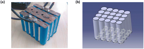 | ||
| Fig. 1 The photo and scheme of mesh for the 4 × 5 battery package.65 | ||
| Value | Parameter | Value | Parameter |
|---|---|---|---|
| 398 W m−1 K−1 | Negative electrode current collector thermal conductivity | 3.7 V | Nominal voltage |
| 0.6 W m−1 K−1 | Electrolyte thermal conductivity | 1.5 A h | Nominal capacity |
| 0.3344 W m−1 K−1 | Separator thermal conductivity | 2 × 10⁻⁴ m | Can thickness |
| 1.5 × 10⁻⁵ m | Positive electrode current collector thickness | 4.54 × 10⁻² kg | Cell mass |
| l × 10−5 m | Negative electrode current collector thickness | 2770 kg m−3 | Positive current collector density |
| 1 × 10⁻⁵ m | Separator thickness | 8933 kg m−3 | Negative current collector density |
| 1.5 × 10⁻⁴ m | Positive electrode thickness | 1500 kg m−3 | Positive electrode density |
| 1.2 × 10⁻⁴ m | Negative electrode thickness | 1347 kg m−3 | Negative electrode density |
| 5.52 × 10⁻² m | Positive electrode height | 1130 kg m−3 | Electrolyte density |
| 0.895 m | Positive electrode length | 659 kg m−3 | Separator density |
| 5.71 × 10⁻² m | Negative electrode height | 700 J kg−1 K−1 | Positive electrode heat capacity |
| 0.936 m | Negative electrode length | 1437 J kg−1 K−1 | Negative electrode heat capacity |
| 5.71 × 10⁻² m | Separator height | 875 J kg−1 K−1 | Positive electrode current collector heat capacity |
| 1.06 m | Separator length | 385 J kg−1 K−1 | Negative electrode current collector heat capacity |
| 5.52 × 10⁻² m | Positive electrode current collector height | 2055 J kg−1 K−1 | Electrolyte heat capacity |
| 0.95 m | Positive electrode current collector length | 1978 J kg−1 K−1 | Separator heat capacity |
| 5.71 × 10⁻² m | Negative electrode current collector height | 5 W m−1 K−1 | Positive electrode thermal conductivity |
| 1.004 m | Negative electrode current collector length | 5 W m−1 K−1 | Negative electrode thermal conductivity |
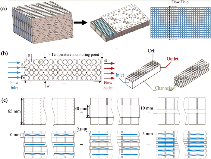 | ||
| Fig. 2 Construction diagrams of (a) the DLC battery pack, (b) battery block, and (c) side views of the battery blocks with different flow channel configurations.69 | ||
A large body of research has shown that when the temperature of a lithium-ion battery exceeds 50.00 °C,70–74 the degradation rate and aging phenomenon of the battery will accelerate. This is a major challenge for the battery to cope with extreme environmental temperatures or during fast charging or discharging, without affecting the cycle life and output performance. Therefore, an appropriate battery thermal management system (BTMS) is crucial and necessary to maintain the optimal operating temperature range, improve durability, and extend the life cycle.
3. Lithium battery thermal management system
A reliable battery thermal management system (BTMS) can effectively address extreme operating conditions75 and is one of the key components of a lithium-ion battery pack.76 It can maintain the operating temperature within the desired range specified by the battery manufacturer and minimize the temperature difference between the battery cells within the module.3.1. Classification of battery thermal management system
An effective Battery Thermal Management System (BTMS) can prevent the heat runaway phenomenon by controlling the temperature within a safe range and managing the heat behavior of the battery.77 A BTMS can ensure that the battery operates within a safe working temperature and has uniform temperature distribution. There are various cooling strategies for the BTMS including air cooling, liquid cooling, phase change material (PCM) cooling, thermal pipe and composite cooling strategies. Table 2 summarizes the advantages and disadvantages of the current BTMS.| Cooling Method | Advantages | Limitations |
|---|---|---|
| Air cooling | 1. Relatively simple structure, low cost and light weight. | 1. The heat conduction coefficient of the air is low, smaller than the heat capacity, and the temperature control capacity under high magnification is relatively weak. The temperature uniformity in the battery pack is relatively poor. |
| 2. The design is easy to realize and adaptable. | 2. When the active cooling method meets the heat management requirements, the power consumption is greater, the space required for the system is larger, and the energy density of the battery pack is smaller. | |
| 3. The potential for improvement is relatively small, and the limited temperature control limit is relatively low. It is mainly suitable for battery packs with small energy density and low charging rates. | ||
| Liquid cooling (indirect) | 1. The specific heat capacity and thermal conductivity of liquids are usually greater compared to air, and cooling is usually better for the same power consumption. | 1. The system structure is more complex, the overall weight is large, and the cost is higher. |
| 2. Cooling effectiveness can be effectively improved by coolant flow, channel design and material properties. The potential for improvement is relatively high. | 2. In order to prevent leakage and short-circuit, the coolant needs to be in indirect contact with the battery cells, which increases the thermal resistance and inhibits the cooling effect. | |
| 3. Temperature uniformity is usually better when the ducts or cooling plates are in contact with the cell side. | 3. The thermal conductivity of the pipeline or cooling plate is large, which is not conducive to suppressing the thermal runaway of the battery pack. | |
| Liquid cooling (direct) | 1. Simple and compact structure, light weight and low cost. | 1. Higher sealing requirements for the battery pack do not allow conductive media to enter the system. |
| 2. The coolant is in direct contact with the battery cells, convection heat transfer is stronger, and the cooling effect is further improved. | 2. Pumps and cooling systems are often required to drive the coolant and reduce its temperature. | |
| 3. The coolant as a medium can avoid short circuits and inhibit the spread of thermal runaway. | ||
| Phase change material (PCM) cooling | 1. PCM absorbs heat and cools down without an additional cooling system. | 1. The volume of the PCM usually changes significantly after a phase change, increasing the potential for leakage. |
| 2. The shape of PCM is easy to change, the system arrangement is simple, and the temperature uniformity is better. | 2. Most PCMs have low thermal conductivity and are less sensitive to temperature changes. | |
| 3. PCM usually has good insulation resistivity and can be used as insulation material to reduce the risk of short circuits. | 3. In the case of continuous circulation, the cooling effect will be reduced, and an additional cooling system is needed to take away the heat absorbed by the PCM. | |
| Heat pipe cooling | 1. Excellent thermal conductivity, a wide range of applications. Sensitive to temperature changes, can effectively control the temperature in real-time. | 1. Complex system structure and difficult to manufacture. |
| 2. Heat pipes work alone without additional power consumption. | 2. High cost and risk of leakage and small thermal capacity. | |
| 3. Small contact area with the battery, usually requiring additional cooling plates to improve temperature uniformity. | ||
| Hybrid cooling | 1. The hybrid thermal management system can supplement its advantages and limitations, and help improve the overall performance of the system. | 1. The increased size and structural complexity of hybrid cooling systems compared to a single thermal management approach, with a corresponding increase in manufacturing and maintenance costs. |
| 2. It can greatly reduce system power consumption to a certain extent. | 2. The greater control difficulty of hybrid cooling systems. |
The simplest and most efficient cooling systems for lithium-ion batteries are passive systems like thermal conductive pipes and phase change materials (PCMs).78–83 These systems are simple in structure and don’t require complicated or large auxiliary equipment, and don’t consume additional energy.84,85 The thermal conductive pipes use their excellent heat conductivity to quickly remove heat generated by the battery, achieving the cooling effect. PCMs are an important heat management material because of their high latent heat, compact structure, and efficiency.86–89 By using composite PCMs made from porous materials and high thermal conductive fillers, the composite PCMs have the advantages of being leak-proof, high in heat conductivity, and able to be processed into any shape. Therefore, PCM cooling systems can be applied to batteries of any shape with good temperature uniformity. In recent years, research on this cooling method has focused on improving the effective thermal conductivity of PCMs.90–92
In active battery cooling systems, the main methods are air cooling and liquid cooling. Air cooling is a common method used in lithium-ion batteries and has been widely studied and researched.93–95 Air cooling modules are widely used in commercial electric vehicles due to their advantages of simple components and parts, easy maintenance, low cost, and light weight.96 To improve the cooling efficiency of air cooling, many studies have been conducted to achieve this goal.97–100
However, air cooling has poor thermal conductivity and smaller heat capacity, leading to lower cooling capacity of the battery thermal management system (BTMS) and poor temperature uniformity among batteries. It loses efficiency when operating under high-temperature conditions.101 Additionally, there are challenges in practical application such as difficulty in using phase change materials (PCMs), increased weight of battery packs, and safety concerns. The shape of the heat pipe also limits its use to specific battery shapes. Many experimental results show that liquid cooling can better suppress the temperature rise compared to PCM and air cooling, as it can absorb more heat and has a smaller volume.102,103
3.2. Liquid cooling
The basic principle of liquid-cooling BTMS is to transfer and dissipate the heat generated by the battery during operation into a liquid coolant and then dissipate it into the environment.104 Liquid cooling can be divided into two different methods: direct cooling and indirect cooling. Immersing the battery cells in an electrically insulated material is a direct liquid cooling method, while indirect cooling can be achieved through liquid flowing over a cool plate or a unit that holds the cells.105 In order to take advantage of the superiority of both direct cooling and indirect cooling methods, a new concept for battery thermal management system has also been proposed in recent years: the hybrid battery thermal management system. PCM cooling, as a passive thermal management method, can be integrated into the battery BTMS, and the integration of PCM and liquid cooling is increasingly being studied as a new and emerging solution for lithium-ion battery hybrid thermal management (HTM).Direct liquid cooling, also known as immersion cooling,106,107 has a simple system design with low thermal resistance and high cooling efficiency. This method uses a heat transfer fluid (HTF) to remove heat from the battery, resulting in a faster and more compact cooling rate than an air-based battery thermal management system (BTMS). As an HTF, it should have superior thermal performance characteristics, such as high thermal conductivity, low viscosity, low density, and better thermophysical properties, and should not react with the battery material.76 Mainly water and oil, such as mineral oil and silicone oil, are used as coolants. Although the coolants are in direct contact with the battery, systems designed with mineral oil and silicone oil are simpler and more compact, saving manufacturing and maintenance costs. However, these coolants have a higher viscosity, consuming more pump power to deliver the same mass flow. Despite recent proposals for direct liquid cooling and limited research, there is still a large gap in the development of direct contact battery thermal management systems.
Despite the high thermal performance of direct contact modes, direct contact between the battery and the HTF may not be practical in battery packs and indirect liquid-based systems are more readily implementable. Effective heat transfer by the coolant is typically achieved through structural design, including separate coolant channels, heat transfer jackets, cold plates, heat pipes (HP), and the like. Indirect contact liquid cooling systems typically require a miniaturized coolant channel for the flow of the coolant, with the battery being surrounded by a cooling plate exterior. Water/ethylene glycol, with its lower viscosity and higher thermal conductivity, is the most common coolant for liquid-cooled BTMS as it is more easily able to provide higher mass flow and lower power consumption. Other cooling systems commonly used include oil, water, nanofluids, liquid metals, and boiling liquids.
Wang et al.108 conducted control tests on several competing cooling strategies, including unidirectional cooling flow, constant-period reciprocating cooling flow, and actively controlled reciprocating cooling flow. It was found that the reciprocating cooling flow could effectively reduce the maximum temperature rise and temperature non-uniformity in the battery pack of actual size. De Vita et al.109 proposed a computational modeling method to characterize the internal temperature distribution of a lithium-ion battery pack, which was used to simulate the liquid cooling strategy for thermal control of the battery pack in automotive applications, highlighting the advantages and disadvantages of the strategy. Fig. 3(a) shows a liquid-cooled battery pack with six adjacent batteries, each with a liquid cooling plate between the six cells. In Fig. 3(b), the difference between the highest and lowest average temperature appears to increase over time, which is why a thermal management system (TMS) is required. Shang et al.110 designed a lithium-ion battery liquid cooling system with a changing contact surface, determined by the width of the cooling plate. The cooling performance and pump power consumption were evaluated through mathematical derivation and numerical analysis. The results showed that the temperature was proportional to the inlet temperature, but inversely proportional to the width of the cooling plate. Through single-factor analysis and orthogonal experiments, three factors affecting the thermal performance of the battery (mass flow rate, inlet temperature, and width of cooling plate) were optimized. The battery model is illustrated in Fig. 3(c). The battery casing and cooling plate are made of aluminum and are very light. The width of the cooling plate varies from 55 mm to 75 mm with an interval of 5 mm. As shown in Fig. 3(d), the width and length of the cooling plate are the same as those of the heat-conducting pad. By using this optimization method, the temperature lower limit and temperature uniformity of the battery were achieved, and the consumption of the pump was reduced.
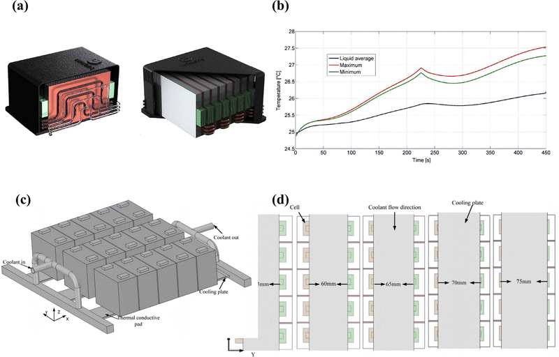 | ||
| Fig. 3 (a) Battery pack render for liquid cooling solution (on the right) and the cross-section view of the cooling channels,109 (b) temperature evolution during a discharging/charging process for liquid cooling simulation,109 (c) 3D model of the battery module and actual picture of single-cell,110 (d) flow characteristics of D-tesla valve design and (e) coolant flow channel with different width of the cooling plate.110 | ||
As demonstrated by the above experiments, it is imperative to study the performance of the cooling system due to the presence of contact thermal resistance between the cooling plate in indirect contact with the cooling system and the battery.111,112 To enhance the thermal performance of lithium-ion batteries, on the one hand, the cooling effect of the coolant on the battery thermal management system (BTMS) is crucial, and some researchers have investigated ways to improve the thermal conductivity of the coolant, such as adding solid particles with high thermal conductivity coefficients to the coolant. On the other hand, the contact area between the battery and the cooling plate and the number of cooling channels also affect the temperature distribution of the battery, so optimizing the system structure can also significantly improve the cooling performance of the BTMS. Meanwhile, the mixture of liquid cooling and other methods is becoming an effective solution to achieve the highest cooling efficiency.
4. Liquid cooling BTMS improvement
The optimization methods for liquid cooling BTMS can be divided into three categories: coolant, system structure, and improvement of liquid cooling-based hybrid systems. The system structure includes the cooling fluid channel, cooling plate, and heat transfer casing.4.1. Coolant improvement
The liquid cooling system has good conductivity, allowing the battery to operate in a suitable environment, which is important for ensuring the normal operation of the lithium-ion battery. Commonly used coolants in cooling systems include oil, water, nanofluids, liquid metals, and boiling liquids.113,114 The four advanced coolants reviewed in this section are oil, electrically conductive coolants, liquid metal or nanoparticle-added coolants, and special coolants.In recent years, the concept of immersion cooling has been put forth and validated through numerical studies. Zhou et al.115 immersed lithium-ion batteries in non-conductive coolant dimethyl silicone oil and employed an electrically coupled heat transfer model to obtain the heat generation rate and temperature distribution of the battery during discharge, as well as to determine the performance of the system via numerical calculation. The BTMS structure of the immersed cooling is illustrated in Fig. 4(a). The results showed that compared to natural cooling, immersion cooling can significantly reduce the maximum temperature (Tmax) of the battery during 3C (C-rate is the measurement of the charge and discharges current with respect to its nominal capacity.) discharge. Liu et al.116 found that the cooling and homogenization performance of transformer oil is superior to that of silicone oil. They used new 18650 lithium-ion batteries/graphite as test subjects, with nominal capacities and charging/discharging cut-off voltages of 2600 mA h and 4.2 V/2.75 V, respectively. Prior to testing, the used batteries were charged and discharged using the Constant Current Charging (CCC) – Constant Voltage Charging (CVC) – Constant Current Discharging (CCD) mode (at a constant rate of 0.5C), through 5 cycles. Fig. 4(b) shows that not only does the transformer oil control the battery temperature below 35 °C, but the temperature deviation is less than 3 °C at discharge rates of 1 to 2C. Wang et al.117 used high insulation No. 10 transformer oil as the immersion-style cooling fluid and built an experimental platform consisting of 5 parallel 10 A h lithium-ion pouch batteries with a total capacity of 10 A h. They studied the cooling performance of liquid-immersed BTMS (Battery Thermal Management System) and its influencing factors. The experimental setup design of the liquid-immersed BTMS is shown in Fig. 4(c). The results showed that under the conditions of a discharge rate of 2C (100 A) and an ambient temperature of 25 °C, the liquid-immersion cooling scheme with an immersion depth of 13.2 cm (full immersion height) and a flow rate of 0.8 L min−1 has the best thermal management performance. In addition, there is also research on mineral oil. Liu et al.118 discussed the thermal behavior of dynamically cycled batteries under static and flowing mineral oil (MO). As shown in the right figure of Fig. 4(d), the experimental platform was filled with MO, the battery was fully immersed in the oil, and connected to the battery cycling tester (NEWARE CT-4008, 5 V/6 A) through nickel strips welded to the positive and negative terminals of the battery. The battery temperature could be maintained below 35 °C at a flow rate of 5 mL min−1, and even at a 4C discharge rate, it could be maintained below 30 °C when the flow rate exceeded 15 mL min−1. Increasing the MO flow rate could reduce the battery temperature, and this effect gradually weakened due to the limit of the system cooling capacity.
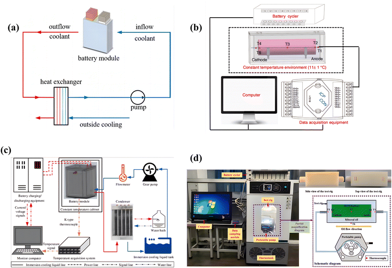 | ||
| Fig. 4 (a) Structure of the BTMS with immersion cooling,115 (b) schematic diagram of the experiment,116 (c) schematic diagram of the experimental system,117 (d) the experimental setup in this work.118 | ||
The mass of liquid-immersed cooling systems in battery packs is much higher compared to air cooling systems due to the immersion of the battery packs. Leakage is a major hazard of cooling systems and the advantages and disadvantages need to be considered in the design process. Oil is a significant refrigerant and is frequently utilized. In the process of designing cooling systems in the future, variables such as the temperature of the cooling fluid inlet (Tin), the outlet velocity (Vout), the inlet velocity (Vin), the flow rate of the cooling fluid (ṁc), the pressure change rate (Δp), and the channel diameter (Dh) must be taken into consideration.
When metal particles are added to traditional fluids, they become nanofluids. When added, the thermal conductivity increases significantly. As a result, the thermal conductivity of metal is much higher than that of traditional heat transfer fluids. Liu et al.123 investigated the thermal performance enhancement of different base fluids, including water, ethylene glycol (EG), and engine oil (EO), by incorporating nanoparticles to explore the effect of nanofluids on the thermal performance of base fluids. The performance of nanofluids was calculated and verified using experimental data. It was found that the thermal performance of water, EG, and EO was improved by incorporating aluminum oxide nanoparticles, but the fluid pressure drop also increased at different discharge rates (i.e., 1C, 2C, 3C). The improvement was more pronounced for base fluids with lower thermal conductivity. The geometric dimensions of the battery pack and the microchannel cooling system are shown in Fig. 5(a). The addition of 2% aluminum oxide in EO and its nanofluid coolant are shown in Fig. 5(b) and (c) at a discharge rate of 1C. In addition to the selection of the base fluid, the thermal performance improvement by different nano-additives also differed. Kiani et al.124 tested various oxide nanofluids, with three types of nanoparticles, aluminum oxide (Al2O3), copper oxide (CuO) and silver oxide (AgO). The nanofluids prepared from Al2O3 and CuO are shown in Fig. 6(a). The experimental results indicated a significant improvement in the cooling efficiency of the nanofluid system, among which AgO was the best candidate. Compared to a battery thermal management system based on pure water, a nanofluid system with a 2% vol concentration of AgO/water reduced the highest temperature of the battery by approximately 4.1 K. As shown in Fig. 6(d), the addition of nanoparticles significantly enhances the heat transfer rate. Fig. 6(e) shows the change of the highest temperature of the battery under different volume fractions of AgO nanoparticles at three different concentrations. Zhou et al.125 also chose a carbon nanotube (CNT) ethanol–water solution as the working fluid, as described in Fig. 6(b), which shows a transmission electron microscopy (TEM) image of the dispersed CNT fibers’ size and shape. A water–ethanol mixed base CNT nanofluid was obtained in different mass concentrations of 0.05–0.5% as shown in Fig. 6(c). The results showed that compared to the ethanol–water mixture, the CNT-based nanofluid has better starting and heat transfer performance for the vertical OHP. The average evaporator temperature and thermal resistance of the OHP were reduced to 43.1 °C and 0.066 °C W−1, respectively, which were 9.8 °C and 0.278 °C W−1 lower than the ethanol–water mixture. Fig. 6(f) lists the overall size and geometric parameters of the mixed OHP. To simulate the battery cooling on the basis of the OHP, the evaporator part of the mixed OHP was sandwiched between two flat heating plates of the same size as the evaporator plate, as shown in Fig. 6(g).
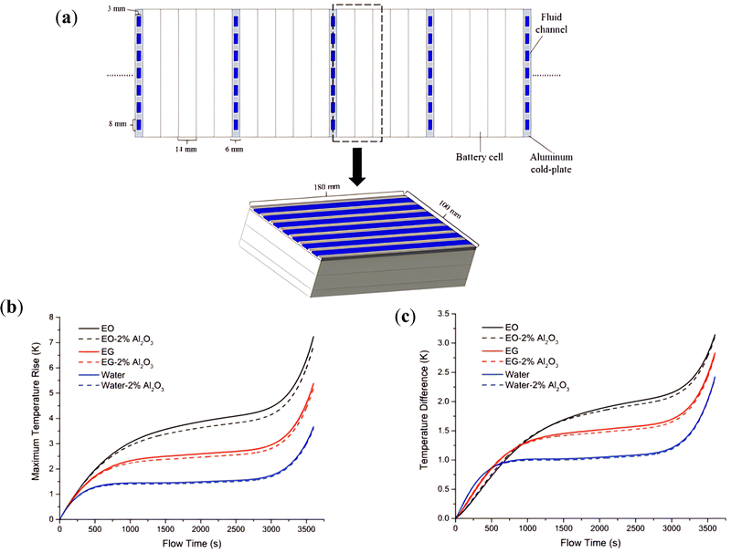 | ||
| Fig. 5 (a) Geometry schematics of the battery pack and simulated battery module, cooling performance enhancement of nanoparticles on, (b) maximum temperature rise and (c) temperature difference at a discharge rate of 1C and Vin = 0.1 m s−1.123 | ||
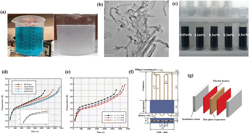 | ||
| Fig. 6 (a) Prepared nanofluid of CuO-Water (left) and Al2O3 (right),124 (b) TEM image of CNT nanofluid,125 (c) photographs of CNT nanofluid samples at different mass concentrations,125 (d) effect of various nanofluids on the cooling system,124 (e) effect of nanoparticle volume fraction on the cooling performance,124 (f) tested hybrid OHP,125 (g) sandwich structure of the battery thermal.125 | ||
In order to study the effect of volume fraction of nanoparticles and flow velocity of nanofluids on cooling performance, Bin-Abdun et al.126 investigated the thermal physical properties and heat transfer rate of CuO/deionized water nanofluids containing and not containing sodium dodecyl sulfate (SDS) surfactant. They analyzed the effect of flow velocity and surfactant on the heat transfer rate of nanofluids at different volume concentrations of 0.08%, 0.16% and 0.40%. The size and morphology of copper oxide nanoparticles are shown in Fig. 7(a). To ensure no settling occurred, the nanofluids were observed for 96 hours, as shown in Fig. 7(b). The results showed that the highest heat transfer rate was obtained for CuO/deionized water nanofluid with a volume concentration of 0.40% and SDS surfactant. The results of the heat transfer rate for deionized water and copper oxide nanoparticles with volume concentrations of 0.08%, 0.16% and 0.40% at different flow velocities are shown in Fig. 7(c). To further investigate the impact of nanofluids on the thermal management of lithium-ion batteries, Yetik et al.127 studied two different base liquids (water and ethylene glycol) and three different volume fractions (1%, 2%, and 5%) of nanoparticles (iron oxide). The batteries were connected in series, and the battery module is shown in Fig. 8(a). The results showed that the cooling effect of the module was better when the volume fraction of the nanofluid and the coolant increased. The impact of the inlet velocity of the cooling fluid on the highest temperature at the outlet of the battery module is shown in Fig. 8(b) under the conditions of a 5C discharge rate and a mixture of water-based 5% iron oxide nanofluid. Fig. 8(c) shows the highest temperature at the end of the 2.5C discharge for the battery module. In their research, Mitra et al.128 prepared nanofluids using multi-walled carbon nanotubes (MWCNTs) with three different volume fractions (Vf) (0.15%, 0.3% and 0.45%) in a mixture of ethylene glycol and water and compared the cooling performance of the nanofluids with that of water and ethylene glycol–water mixtures. The assembly of serpentine channels is described in Fig. 8(d), where aluminum channels are stacked on top of each other between the batteries to allow maximum contact with heat extracted from the laboratory. Fig. 8(e) describes the temperature profile of the batteries and serpentine channels for different working fluids at a discharge rate of 2.1C. It can be observed that due to the lower temperature of the working fluid, the starting temperature of the battery module is lower. The results show that the use of nanofluids significantly reduces the temperature deviation of the battery module and the temperature profile helps to study the temperature difference at different discharge rates, where the cooling performance is best for the nanofluid with Vf of 0.45% (0.45% of the volume in the nanofluid is nanoparticles, and the rest is the base fluid), as shown in Fig. 8(f).
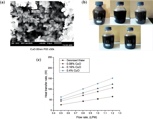 | ||
| Fig. 7 (a) SEM images of CuO nanoparticles,126 (b) stability of CuO/deionized water nanofluid (with surfactant),126 and (c) heat transfer rate versus flow rate for deionized water and nanofluids.126 | ||
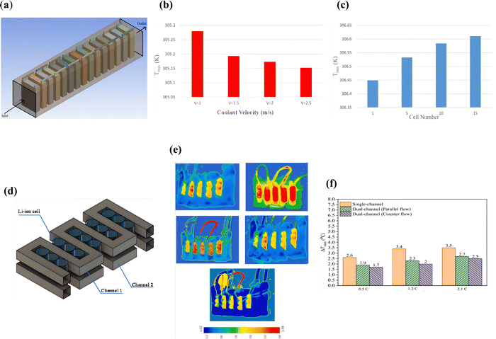 | ||
| Fig. 8 (a) The battery module,127 (b) effect of coolant flow velocity on maximum temperature,127 (c) distribution of maximum temperature of the battery module, from cell to cell at the end of discharge rate of 2.5C, Velocity inlet = 2.0 m s−1; coolant is EG-H2O with 2% Fe2O3,127 (d) assembly of the serpentine channel with LIBs,128 and (e) thermal image of LIBs for different working fluids water, binary fluid, 0.15% Vf of MWCNT, 0.30% Vf of MWCNT and 0.45% Vf of MWCNT after 600 s at 2.1C,128 (f) 0.45% Vf of MWCNT in the base fluid128. | ||
In recent research, Ouyang et al.129 proposed an efficient and energy-saving battery thermal management system that integrates phase change cooling, nanofluid cooling, and insulation materials. The effects of the volume fraction of nanoparticles and the flow rate of nanofluids on cooling performance were studied. Furthermore, to further improve cooling performance, a uniformly accurate rotatable composite material with a uniform precision was adopted and a regression equation was established to determine the optimal combination factor. First, the flow rate of the nanofluid was set at 0.01 m s−1. Observing Fig. 9(a), the trend of battery temperature change at different volume fractions is the same, but the highest temperature is different. In Fig. 9(b), the maximum temperature of the battery rises and then decreases, but the decreasing range gradually decreases. Using the regression equation, an improved plan was obtained. The flow rate of the nanofluid, the volume fraction of the nanoparticles, the thickness of the phase change materials, and insulation materials were 0.05 m s−1, 1%, and 3 mm, respectively. By comparing the improved plan with the original plan, the highest temperature of the battery was reduced by 23% and the economic index was reduced by 22%.
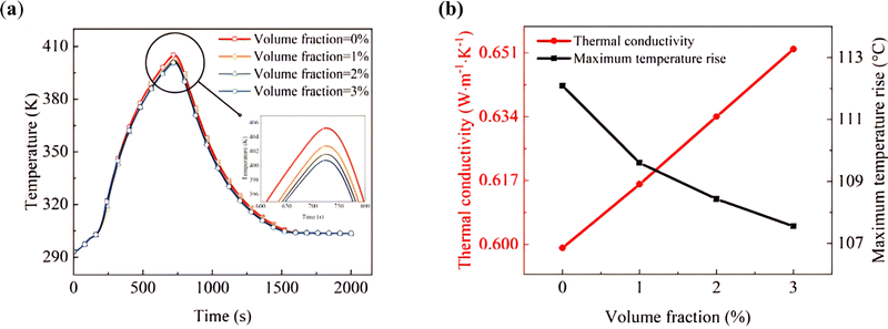 | ||
| Fig. 9 Effect of nanoparticle volume fraction on the novel BTMS: (a) temperature change under different nanoparticle volume fractions;129 (b) thermal conductivity and maximum temperature rise under different nanoparticle volume fractions.129 | ||
In recent years, experimental and theoretical studies on the performance and properties of nanofluids have been conducted.130–135 It can be concluded from the existing literature that the improvement in the heat transfer rate of nanofluids depends on certain factors such as temperature, particle volume concentration, shape and size of nanoparticles, and heat transfer characteristics of the base fluid. However, the development of nanofluid technology is hindered by several challenges including stability issues, higher pumping power requirements due to increased viscosity, and the high cost of synthesizing nanoparticles.
4.2. Optimization of liquid cooling system structure
In the case of indirect cooling methods, thermal resistance needs to be taken into account more carefully due to the addition of channel materials and electrical insulation coatings. To improve the cooling performance of the cooling system, the system structure can be optimized. The optimization of the cooling system structure starts with the improvement of the cooling plate, channel shape structure, and heat exchanger.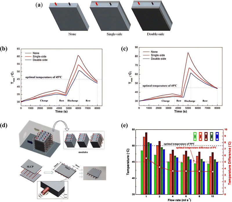 | ||
| Fig. 10 (a) Design with different numbers of thermal silica plates. Maximum temperature of the battery under different numbers of thermal silica plates when discharged at,139 (b) 3C-rate and,139 (c) 5C-rate,139 (d) schematic diagram of battery module cooling system; geometry structure of the silica plate/liquid coupled cooled plate (SLCP),140 (e) temperature distributions and temperature differences of the module with silica plate/liquid coupled cooled plate under different water velocity at the end of the sixth discharge cycle.140 | ||
The cooling effect of a microchannel cold plate is superior to that of a conventional water-cooled plate. Tang et al.141 proposed a water-cooling strategy combining microchannels to achieve heat dissipation for a lithium-ion battery pack and further optimized the cooling plate. The designs of the three cooling structures are shown in Fig. 11(a), and the maximum temperature (Tmax) of the battery under different cooling structures at a discharge rate of 1C is shown in Fig. 11(b). As can be seen from the figure, the cooling plate structure at the bottom and on both sides of the battery module can achieve optimal cooling performance. This study can provide guidance for the thermal management of large-capacity square batteries. For the placement of cooling plates, Wu et al.142 studied a 30 A h LiFePO4 (LFP) pouch cell and designed a three-sided liquid cooling structure that takes into account the preheating of the battery module. The cooling plate structure and the preheating structure of the battery pack are shown in Fig. 11(c). The research results show that the arrangement of the cooling plate and the inlet temperature has a significant impact on the preheating effect, and the optimized external preheating structure can keep the preheating temperature difference of the battery module below 5 °C. Based on this, the proposed combined internal and external preheating strategy saves 50% of the preheating time compared with the three-sided preheating strategy. To further investigate the two designs with superior cooling performance and the baseline cold plate, Yang et al.143 systematically analyzed nine different cold plate designs, including a baseline cold plate without PCM composite material and eight mixed cold plates containing PCM composite materials, to demonstrate that the proposed cooling designs have superior cooling performance. Fig. 11(d) shows a schematic of the lithium-ion BTMS, which consists of a battery cell, a mixed cold plate integrated with PCM/aluminum foam composite material, and a liquid delivery manifold with multiple inlets and outlets. The results show that the optimal mixed cold plate design, which is only half of the baseline cold plate, can reduce the total pumping power by more than 50% while achieving the same cooling performance (i.e., controlling the average battery temperature within 40 °C).
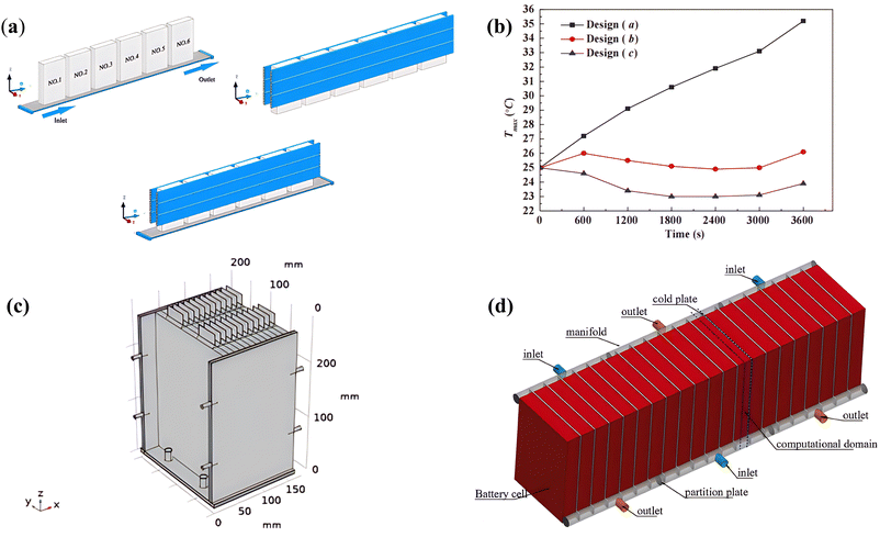 | ||
| Fig. 11 (a) Three placement strategies of cold plate: at the bottom; on two side walls; at the bottom and on two side walls,141 (b) maximum temperature rise curves of the battery pack under different cooling structures,141 (c) three-sided preheating structure,142 (d) the schematic of the lithium-ion battery thermal management system.143 | ||
The optimization of cooling plates for liquid cooling systems has been extensively studied, but further research is needed to improve the temperature uniformity of batteries. Chung et al.144 investigated the structural features that affect cooling performance and temperature uniformity using a typical battery pack design as a reference model. They proposed two strategies, including alternative combinations of battery stack and cooling plates, and a symmetric stack arrangement. Fig. 12(a) shows a schematic diagram of a practical and typical battery pack structure with metal fins and cooling plates. The main reason for the poor thermal conductivity of the battery pack design with metal fins and cooling plates was found to be the thermal resistance between the bottom of the stack and the cooling plate. The adoption of a D-type (D-2 type) symmetric stack arrangement reduced the increase in the equivalent thermal conduction of the system volume to 38%, and the maximum temperature difference was reduced to 5.4 °C. However, designing a suitable Battery Thermal Management System (BTMS) is essential for the reliability and safety of the energy storage system (ESS) in electric vehicles. In Karimi et al.'s study,145 a liquid-based BTMS was designed for a prismatic high-power Lithium Capacitor (LiC). The proposed BTMS integrates a LiC unit surrounded by two cooling plates, as shown in Fig. 12(b), with the coolant flowing through a serpentine channel. The effect of the selected Thermal Interface Material (TIM) was also studied, as the gap filler eliminates the air gap barrier between the battery and cooling plate. Li et al.146 proposed a composite liquid cooling system that combines a grooved aluminum vapor chamber with a single-pass cold plate and experimentally studied its thermal performance. Fig. 12(c) shows the mass transfer cycle of the phase inside the vapor chamber, representing the cross-section of the grooves. The results indicate that a vapor chamber with 20% to 30% of the horizontal structure has the lowest thermal resistance and better temperature uniformity. Due to the thermal and mass transfer of the phase along the vertical direction inside the vapor chamber, the temperature difference of the heated surface caused by the temperature rise of the coolant can be effectively suppressed.
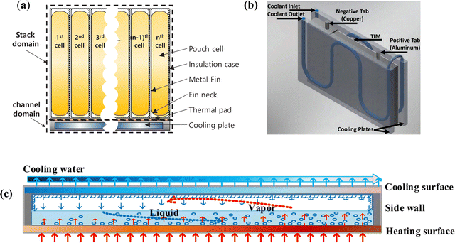 | ||
| Fig. 12 (a) Typical structure of battery stack with metal fin and cooling plate,144 (b) the geometry of the proposed liquid-based TMS,145 (c) schematic of the longitudinal section of the vapor chamber.146 | ||
To discuss the influence of key structural parameters and operating conditions of battery modules on the thermal performance, including the shape of the cooling plate and the number of cooling plates and tube joints, Yang et al.147 proposed a new honeycomb-shaped Battery Thermal Management System (BTMS) that integrates hexagonal cooling plates with bio-inspired liquid microchannels inspired by the structures of spider webs and honeycombs. (Fig. 13) shows the honeycomb-shaped BTMS integrated with hexagonal cooling plates and PCM. Compared with rectangular cooling plates, at an inlet flow rate of 0.001 kg s−1, Tmax, ΔT, and pressure drop of the battery module with hexagonal cooling plates were reduced by 0.36 K, 2.3 K, and 4.37 Pa, respectively.
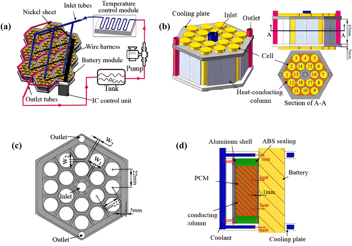 | ||
| Fig. 13 Scheme of battery thermal management system.147 | ||
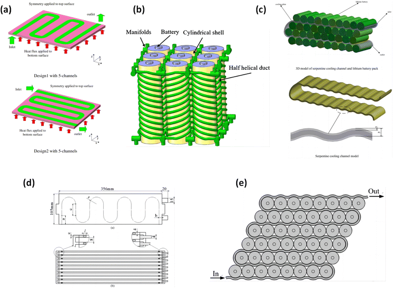 | ||
| Fig. 14 (a) The CFD model of the cold plate,150 (b) schematic diagram of battery module using half-helical duct,151 (c) the structure of the serpentine cooling channel of the cooling and heat dissipation system,152 (d) planar diagram of a serpentine liquid cooling BTMS; top view,154 and (e) structure of a liquid cooling lithium battery pack.155 | ||
Microchannels or sub-microchannels have been widely used for cooling microelectronic components. It has been reported that heat sinks with microchannels are typically used to enhance cooling in high heat flux areas. To improve the heat transfer capability of microchannels, new or improved design features of microchannels are often adopted. Liu et al.153 proposed a T-Y microchannel heat sink (MCHS) based on T-shaped and Y-shaped channel designs. Compared with traditional straight channels, the T-Y microchannel has a stronger heat transfer enhancement ability due to its additional corners, junctions, and shortened flow path. Through Fluent-3D numerical simulation, they systematically studied the heat transfer performance of the T-Y heat sink with different inlet mass flow rates and other structural parameters using liquid GaInSn coolant. Wang et al.154 studied a liquid-cooled BTMS with microchannels featuring a serpentine design. They investigated the arrangement of the serpentine microchannels on the cooling plate. As shown in Fig. 14(d). Xie et al.155 proposed an improved method for enhancing the cooling performance by adding baffles in microchannels. The battery pack under consideration consisted of 48 18![[thin space (1/6-em)]](https://www.rsc.org/images/entities/char_2009.gif) 650-type 2.2 A h LIBs, as shown in Fig. 14(e). The position and number of baffles were discussed, and the cooling efficiency in the battery module was optimized. It was found that the heat transfer performance of the battery pack could be further enhanced with increasing baffle height and number. Microchannel technology is a promising solution for battery thermal management systems (BTMS).
650-type 2.2 A h LIBs, as shown in Fig. 14(e). The position and number of baffles were discussed, and the cooling efficiency in the battery module was optimized. It was found that the heat transfer performance of the battery pack could be further enhanced with increasing baffle height and number. Microchannel technology is a promising solution for battery thermal management systems (BTMS).
Due to the large number of parameters involved in the design space of BTMS using microchannel technology, conducting parameter studies and optimization for the system is challenging. Li et al.156 proposed a comprehensive approach to designing an efficient microchannel cooling system that includes thermodynamic, fluid dynamics, and structural analysis. The energy conservation eqn (1), the energy conservation eqn (2) of cooling water, the continuity eqn (3) and the momentum conservation eqn (4) are used to solve the temperature of a single battery cell:
 | (1) |
 | (2) |
∇·![[v with combining right harpoon above (vector)]](https://www.rsc.org/images/entities/i_char_0076_20d1.gif) = 0 = 0 | (3) |
 | (4) |
![[v with combining right harpoon above (vector)]](https://www.rsc.org/images/entities/i_char_0076_20d1.gif) , ρ, and μ denote the mass density, specific heat, thermal conductivity, temperature, velocity, static pressure, and dynamic viscosity of the cooling water, respectively.
, ρ, and μ denote the mass density, specific heat, thermal conductivity, temperature, velocity, static pressure, and dynamic viscosity of the cooling water, respectively.
The design of the development method mainly includes four steps: the design and computational fluid dynamics analysis of the microchannel cooling system, the selection of the experimental design and surrogate models, the formulation of optimization models, and the multi-objective optimization of the microchannel cooling BTMS optimization scheme. The research results showed that the temperature difference decreased from 8.0878 to 7.6267 K (5.70%), the standard temperature deviation decreased from 2.1346 K to 2.1172 K, and the pressure drop decreased from 302.14 Pa to 167.60 Pa. Sheng et al.157 used the FloEFD software for numerical analysis to study the effects of flow direction, flow rate, and channel width of the cooling plate on the cell temperature distribution under different operating conditions. The results showed that the inlet and outlet positions, as well as the flow direction, had a significant impact on the battery temperature distribution and the cooling plate power ratio. The channel width also had a significant effect on its power ratio and battery temperature distribution. Wang et al.158 proposed a simplified yet effective strategy that coupled one-factor-at-a-time analysis with orthogonal testing to systematically study the effects of inlet velocity, number of channels, and contact angle on cooling performance and optimize the structure. The influence levels of these factors followed the order of contact angle > inlet velocity > number of channels, indicating that the contact angle had the greatest impact on the cooling performance and should be fixed at around 70 degrees. Patil et al.159 recommended an optimal cooling strategy by considering the effects of various parameters, including different discharge rates, inlet coolant mass flow rate, and inlet coolant temperature, by changing the surface area coverage of the cooling channels, a maximum width of the cooling channels, and flow pattern layout. Yang et al.160 designed a parallel liquid-cooled battery thermal management system with different flow paths by changing the positions of the coolant inlet and outlet and studied the effect of the flow paths on the heat dissipation performance of the battery thermal management system. The results and analysis showed that the system could achieve the best heat dissipation performance when the inlet and outlet were located in the middle of the first and second main branches, with a maximum temperature decrease of 0.49 °C and a maximum temperature difference decrease of 0.52 °C. Duan et al.161 conducted a numerical study on the three-dimensional temperature distribution in a liquid-cooled battery system and evaluated the influence of channel size and inlet boundary conditions on the temperature field of the battery module. The results showed that the channel width of the cooling plate has a significant impact on the maximum temperature of the battery module. The study also showed that increasing the inlet flow rate can significantly improve the heat transfer capacity of the battery thermal management system, but the relationship between the two is not proportional. Yates et al.162 studied the performance of two liquid cooling designs for lithium-ion battery packs by establishing a series of numerical models. The effects of channel number, aperture, mass flow rate, and inlet position on the small channel cooling cylinder (MCC) and the channel cooling heat sink (CCHS) were investigated. The results showed that for designs with mass flow rates greater than 5 × 10⁻⁵ kg s−1, the highest temperature can be controlled below 313 K, and the maximum temperature variation for both designs can be controlled within 3.15 K. Considering the highest temperature and temperature uniformity, the MCC design provided better performance than the CCHS design.
Gao et al.163 developed a new liquid cooling structure based on a flow-gradient channel (GCD) design and applied it to a cylindrical lithium-ion battery module (Fig. 15(a)). The GCD design, consisting of cooling pipes and multiple cell rows, significantly changed the basic feature of monotonically increasing temperature along the flow direction compared to the uniform channel design. The combination of the number and length of the optimized sections was also improved. Ke et al.164 used a serpentine channel Liquid-Cooled BTMS in parallel to analyze the effect of different cooling liquid flow rates (0 L h−1, 32 L h−1, 64 L h−1, and 96 L h−1) on the propagation of TR in the battery pack. The battery module consisted of 10 batteries equipped with a serpentine cooling channel, an electric heater, and some thermocouples, as shown in Fig. 15(b). The final relationship between TR prevention and the flow rate was studied. For lower cooling liquid flow rate values (0 L h−1, 32 L h−1, and 64 L h−1), the TR rate in the battery was almost random, but for 96 L h−1, TR propagation could be effectively prevented. Sarchami et al.165 studied a new thermal management system that includes a wave/staircase channel liquid cooling and a copper casing to control the temperature of cylindrical lithium-ion batteries. They investigated the effects of different variables on the cooling performance during charge and discharge operation, such as the carbon rate, the alumina nanoparticle concentration, the inflow rate, and the geometric shape of the staircase channels. Khoshvaght-Aliabadi et al.166 proposed a wave microchannel structure with co-current and counter-current working modes and studied its performance using a 3D conjugate numerical model and experimental verification. Fig. 15(c) shows a schematic diagram of the studied case, which includes both conventional and non-uniform wavy microchannels. The current operating mode was found to be the key factor affecting temperature uniformity. Increasing the coolant velocity from 0.106 to 0.951 m s−1 in the co-current mode reduced the temperature non-uniformity from 14.79 to 1.10 K, while the range in the counter-current mode decreased from 6.73 to 0.43 K. Mohammed et al.167 investigated a BTMS composed of a fluid channel heat sink and phase change materials (PCMs). The results showed that, compared to increasing the fluid channel width, the BTMS had better temperature uniformity with a temperature increase of more than 2.85 K for the same volume of heat sink and battery cells. Ren et al.168 developed a bottom liquid cooling (BLC) method based on a multi-channel flat tube (MCFT). A comparative experiment with passive cooling was conducted to analyze the temperature distribution of the battery module according to the BLC method. Fig. 15(d) shows the outline of the module, which consisted of a LIB, MCFT, and an aluminum shell. The results demonstrated that the MCFT-based BLC TMS significantly improved the temperature uniformity of the module while effectively reducing the temperature rise of the battery module.
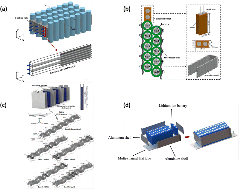 | ||
| Fig. 15 (a) Schematics of liquid-cooled BTMS with GCD,163 (b) schematic of the battery module with the serpentine cooling channel, the electric heater and thermocouples,164 (c) details of physical models,166 (d) structure diagram of the BLC TMS based on MCFT.168 | ||
From the summary of the literature above, we can conclude that microchannel cooling technology has been widely applied in high heat flux areas with weight and volume limitations to address the cooling issue of high-speed integrated circuits. Its heat dissipation performance is significantly better than traditional cooling methods.
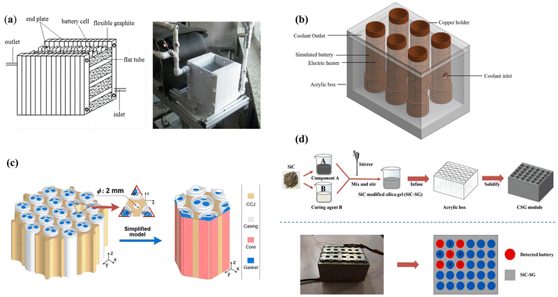 | ||
Fig. 16 (a) Battery pack and cooling structure,169 (b) structure of the battery pack simulation set,170 (c) battery module consisting of multiple 21![[thin space (1/6-em)]](https://www.rsc.org/images/entities/char_2009.gif) 700 cells and simplified CAD model for the module,171 and (d) manufacture of CSG and configuration of detected batteries.173 700 cells and simplified CAD model for the module,171 and (d) manufacture of CSG and configuration of detected batteries.173 | ||
In addition to changes in the external structure, there are also changes in the internal geometry. Lai et al.174 developed a thermal conduction structure (TCS) with three curved contact surfaces to cool cylindrical cells, which is a compact and lightweight cooling structure to increase the heat transfer coefficient between cylindrical cells and coolants, as shown in Fig. 17(a). The designed TCS can control Tmax at 313 K with a DT of 4.137 K. Compared with the original TCS, the designed TCS reduces DP, DT, and weight by 80%, 14%, and 46%, respectively. Tang et al.175 used straight microchannel flat tubes and heat-conducting blocks with gradient contact angles to improve the temperature uniformity of cylindrical lithium-ion battery modules. The key parameters of the heat-conducting block are shown in Fig. 17(b). Liu et al.176 proposed a novel liquid cooling system, named BTMS, based on a tube vertical layout (VLT) and the combination of gradient incremental tube diameter and the gradient ratio of the fluid medium flow rate, as shown in Fig. 17(c). The results showed that the battery module with a tube vertical layout had better performance than the horizontal layout within a certain range of flow rate.
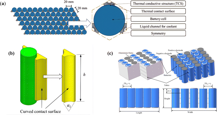 | ||
| Fig. 17 (a) Top view of the TCSs and the batteries,174 (b) key parameter of a heat-conductive block,174 (c) three-dimensional model of the battery module.176 | ||
Based on the literature review above, we can conclude that if the coolant channels for liquid-cooled BTMS are the arteries and veins, then the heat transfer sheath can be regarded as a capillary system connecting the channels and battery cells, which can further improve the heat transfer coefficient of the basic coolant channels.
4.3. Liquid-cooling based hybrid system improvement
Liquid can provide ideal cooling performance, and PCM can improve temperature uniformity. Therefore, this section mainly introduces the active (liquid) and passive (PCM) cooling methods that have been commonly used for the thermal management of lithium-ion batteries in recent years.Although the use of PCM can keep the temperature of the package within a certain range, some auxiliary mechanisms are needed to smoothly dissipate the heat to improve the thermal performance of the package. Studies have shown that the presence of a cooling plate can effectively improve the temperature uniformity inside the unit. A mixed system with phase change material embedded in the cooling plate is called a “hybrid liquid-cooled plate”.177
Cooling plate/phase change material lithium battery module provides a heating solution to mitigate the temperature loss of batteries and has many advantages compared to traditional cooling plates. Akbarzadeh37 found that the volume of the new liquid-cooled plate (LCP) embedded with phase change material (PCM) is 36% lighter than that of traditional aluminum LCP. In addition to cooling capability, the hybrid cooling plate can also prevent the battery from rapidly cooling in cold climates by releasing the latent heat of the PCM. The internal design of the cooling plate is shown in Fig. 18(a). To reduce the weight and volume of this battery thermal management system, Ling et al.178 developed an optimization method based on response surface methodology (RSM) and numerical heat transfer modeling to optimize the composition of phase change material (PCM) and active cooling structure. To further investigate the cooling effect of hybrid cooling plates on lithium-ion batteries, Bai et al.179 designed a battery module with phase change material/water cooling plates as shown in Fig. 18(b), and conducted a numerical analysis based on energy-saving and fluid dynamics. The effects of water cooling plate height, adjacent cell spacing, inlet mass flow rate, flow direction, thermal conductivity, and melting point on the temperature field of the module and cooling water pressure drop were discussed. Fig. 18(c) shows the highest temperature, lowest temperature, and highest temperature difference of each group under different heights of cooling plates at the end of 2C discharge. It was found that PCM/water cooling plates provided good cooling efficiency in controlling the temperature of the lithium-ion battery module, and the 5 cm high cooling plate had the best cooling performance. In order to improve the severe temperature rise and non-uniformity of prismatic lithium-ion batteries, An et al.180 proposed a chocolate bar-shaped hybrid battery thermal management system that combines a metal lattice paraffin liquid cooling plate. By using a multi-objective optimization method, the optimal structural parameters of the system were obtained. Fig. 18(d) shows the three-dimensional geometric model of the proposed HTMS. It was found that the metal lattice plate with phase change material had the best cooling performance and the highest mass group efficiency compared to other hybrid cooling systems. The highest temperature, temperature difference, and group efficiency of the module were 44.95 °C, 4.35 °C, and 78.98%, respectively.
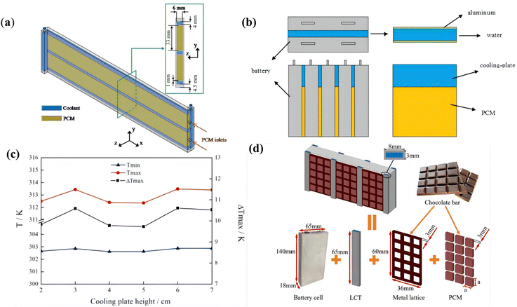 | ||
| Fig. 18 (a) Interior structure of the cooling plate,37 (b) schematic of lithium-ion battery module with PCM/water cooling-plate,179 (c) temperature of the module under different cooling plate height,179 and (d) the HTMS of the battery cell.180 | ||
In addition to being combined with traditional cooling plates, recent research has found that coupling microchannel cooling plates with PCM is also an effective solution to improve the cooling properties of lithium-ion batteries. Mashayekhi et al.49 used a combination of block refined paraffin and porous copper metal foam as the passive part and used an aluminum microchannel with coolant flow as the active part of the TMS. The thermal responses of the battery were compared under passive, active, and hybrid thermal management systems. The results showed that at 3.7 W, the HTMS could reduce the steady-state temperature of the battery by 19.5%. At 12.5 W, the use of HTMS was effective enough to keep the temperature at a stable level of 52 °C, far below the safety limit of Re = 340. It was also found that at a discharge rate of 4C, the steady-state temperature of the nano-fluids with 1% and 2% concentration was 59.2 °C and 57.5 °C, respectively. Mousavi et al.181 designed a novel hybrid mini-channel cold plate (HMCPs) by incorporating PCM (n-eicosane) into the cold plate and investigated its performance under both constant and pulsed heat generation conditions. The experiments showed that compared to MCP cooling with Q of 100, 200, and 400 kW m−3, the time-averaged maximum battery temperature during HMCP cooling was lower by 0.06, 1, and 10.35 K, respectively. Under multiple pulsed heat generation conditions, the time-averaged difference in maximum temperature between the hybrid system and the active system was less than 1 K. Wang et al.182 have developed an innovative system based on phase change material (PCM) and a wavy microchannel cold plate (WMCP) and analyzed and optimized its parameters. Under pulsed heat load, it was found that the highest temperature of the HWMCP was 2.3 K lower than that of the WMCP at 400 s, and the temperature difference was reduced by 0.5 K. Between 300 s and 400 s, the highest temperature of the HWMCP was always more than 2.1 K lower than the WMCP.
Fan et al.183 proposed a battery thermal management system that combines multi-stage Tesla valve (MSTV) liquid cooling and phase change material (PCM). Using the Kriging approximation model, a complex nonlinear hybrid model was constructed between battery spacing, MSTV channel number, coolant velocity, and PCM performance (pressure drop, surface temperature standard deviation, and maximum temperature). As shown in Fig. 19(a), the submodule consists of 20 lithium-ion batteries. As shown in Fig. 19(b), the unit spacing of PCM (Sx, Sy) and the machining allowance (Rx, Ry) are considered. Three liquid cooling plates are arranged radially in the battery module, and MSTV is embedded in the cold plate. Fig. 19(c) shows a cooling plate with N = 5 stages designed using MSTV channels. Yang et al.184 developed a thermal model for pouch cell battery packs based on PCM/liquid composite cooling systems. Through numerical analysis, they compared the cooling effectiveness of different cooling schemes and investigated the influence of PCM thickness, channel width, and coolant flow rate on cooling performance. Their developed thermal model is applicable for evaluating and analyzing the performance of PCM/liquid composite (or liquid-based) cooling systems with start-stop control, which is beneficial for optimizing their control strategies and geometric structures. Zhang et al.185 have designed a novel hybrid BTMS based on PCM and liquid cooling. Subsequently, they established a numerical heat transfer model and a battery thermal runaway model for this system, which were then validated. Using the established models, the performance of the system was investigated in extreme operating conditions to control the battery temperature difference and to prevent thermal runaway propagation under abusive conditions. Furthermore, the influence of PCM thermal conductivity and liquid flow rate on preventing thermal runaway propagation was analyzed in detail. Liu et al.186 conducted experiments and simulations on the thermal management of liquid-cooled lithium-ion batteries using phase change materials as the basis. They used paraffin as the phase change material and established a geometric model and performed heat transfer simulations using COMSOL software. The simulation results indicated that various factors would affect the degree and mode of battery cooling. The experimental results demonstrated that the cooling range was directly proportional to the condensate flow rate, and the initial temperature difference between the battery and the phase change material was directly proportional to the cooling effect.
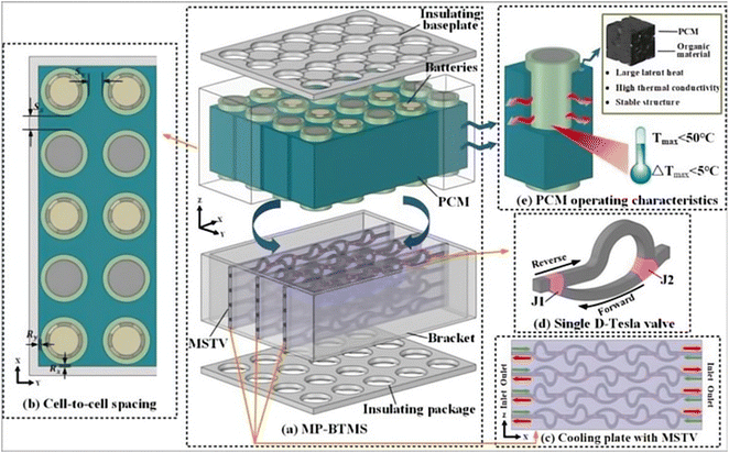 | ||
| Fig. 19 Design of MP-BTMS: (a) the overall system, (b) the spacing between batteries, (c) cooling plate with MSTV channel, (d) flow characteristics of D-Tesla valve design and (e) PCM operating characteristics.183 | ||
All types of battery thermal management system (BTMS) cooling methods have their advantages and disadvantages, and liquid-cooled BTMS is no exception. Hybrid electric vehicle (HEV) BTMS based on liquid cooling have become increasingly popular due to their unique features of using other methods to compensate for the drawbacks of the cooling method itself.
5. Summary and prospect
The research provides a comprehensive overview of design improvement techniques, emphasizing their effectiveness in enhancing cooling performance. Factors such as coolant selection, flow rate, temperature, and system geometry greatly influence the overall system performance. Among the design approaches, improved external coolant channel designs offer advantages for cylindrical batteries, while cooling plate designs show improved performance for prismatic batteries.The integration of Phase Change Materials (PCM) and liquid cooling as a hybrid thermal management (HTM) solution shows promise. However, challenges such as utilizing PCM molded batteries, increased battery pack weight, and safety considerations need to be addressed. Future research should focus on developing enhanced liquid coolants, simplifying cooling channels, and optimizing heat transfer sleeves and plates. Exploring diverse cooling methods with varying compatibility holds potential for liquid cooling solutions in commercial electric vehicles.
In summary, this research emphasizes the immense potential of liquid-cooled BTMS in improving the thermal management of lithium-ion batteries, calling for further advancements and optimizations in liquid-cooling technology.
Nomenclature
| LIB | Lithium-ion batteries |
| BTMS | Battery thermal management system |
| PCM | Phase change material |
| EVs | Electric vehicles |
| BEVs | Battery electric vehicles |
| TR | Thermal runaway |
| HP | Heat pipe |
| DLC | Direct liquid cooling |
| HTF | Heat transfer fluid |
| BLC | Bottom liquid cooling |
| HFE | Hydrogen fluoride ether |
| HTM | Hybrid thermal management |
| MWCNTs | multi-walled carbon nanotubes |
| HEV | Hybrid electric vehicle |
| SLCP | Silicon liquid-coupled cooling plate |
| EG | Ethylene glycol |
| EO | Engine oil |
| CNT | Carbon nanotube |
| CFD | Computational fluid dynamics |
| MTD | Maximum temperature difference |
| GCD | Gradient channel design |
| MCFT | Multi-channel flat tube |
| TIM | Thermal interface material |
| CSGP | Composite silicone gel plate |
| TCS | Thermal conductivity structure |
| VLT | Vertical layout |
| HMCP | Hybrid mini-channel cold plate |
| WMCP | Wavy microchannel cold plate |
| MSTV | Multi-stage tesla valve |
| MCHS | Microchannel heat sink |
| MO | Mineral oil |
| TEM | Transmission electron microscopy |
| OHP | Oscillating heat pipe |
| SDS | Sodium dodecyl sulfate |
| VLT | Tube vertical layout |
| ΔT | Temperature difference (°C) |
| C | Charge/discharge rate |
| V | Voltage (V) |
| A | Current (A) |
| T | Temperature (°C) |
| T max | Maximum temperature (°C) |
| s | Seconds (s) |
Conflicts of interest
The authors declare that they have no conflict of interest regarding the publication of this paper.Acknowledgements
This research was funded by the National Natural Science Foundation of China (No. 51707028), the Chongqing Natural Science Foundation (No. cstc2021jcyj-msxmX0470), and the Science and Technology Funds of Chongqing Municipal Education Commission (KJQN202100533).References
- Y. Manoharan, et al., Hydrogen Fuel Cell Vehicles; Current Status and Future Prospect, Appl. Sci., 2019, 9(11), 2296, DOI:10.3390/app9112296.
- Y. Zhao, et al., Active cooling-based battery thermal management using composite phase change materials, Energy Procedia, 2019, 158, 4933–4940, DOI:10.1016/j.egypro.2019.01.697.
- R. Hou, et al., Introducing electric vehicles? Impact of network effect on profits and social welfare, Energy, 2022, 243, 123002, DOI:10.1016/j.energy.2021.123002.
- H. Zhou, et al., Thermal performance of cylindrical Lithium-ion battery thermal management system based on air distribution pipe, Int. J. Heat Mass Transfer, 2019, 175, 115331, DOI:10.1016/j.ijheatmasstransfer.2018.11.116.
- S. Hardman, et al., Who are the early adopters of fuel cell vehicles?, Int. J. Hydrogen Energy, 2018, 43(37), 17857–17866, DOI:10.1016/j.ijhydene.2018.08.006.
- G. Liao, et al., Thermal performance of lithium-ion battery thermal management system based on nanofluid, Appl. Therm. Eng., 2022, 216, 118997, DOI:10.1016/j.applthermaleng.2022.118997.
- Q. Wang, et al., A review of lithium ion battery failure mechanisms and fire prevention strategies, Prog. Energy Combust. Sci., 2019, 73, 95–131, DOI:10.1016/j.pecs.2019.03.002.
- M. Fernández, et al., The use of activated carbon and graphite for the development of lead-acid batteries for hybrid vehicle applications, J. Power Sources, 2010, 195(14), 4458–4469, DOI:10.1016/j.jpowsour.2009.12.131.
- C. Jie Deng, et al., Electric Vehicles Batteries: Requirements and Challenges, Joule, 2020, 4(3), 511–515, DOI:10.1016/j.joule.2020.01.013.
- T. Kim, et al., Lithium-ion batteries: outlook on present, future, and hybridized technologies, J. Mater. Chem., 2019,(7), 2942–2964, 10.1039/c8ta10513h.
- S. Li, et al., Progress and Perspective of Ceramic/Polymer Composite Solid Electrolytes for Lithium Batteries, Adv. Sci., 2020, 7(5), 1903088, DOI:10.1002/advs.201903088.
- Y. Lu, et al., Prospects of organic electrode materials for practical lithium batteries, Nat. Rev. Chem., 2020, 4(3), 127–142, DOI:10.1038/s41570-020-0160-9.
- Y. Deng, et al., Feature parameter extraction and intelligent estimation of the State-of-Health of lithium-ion batteries, Energy, 2019, 176, 91–102, DOI:10.1016/j.Energy2019.03.177.
- A. Mitra, et al., Advances in the improvement of thermal-conductivity of phase change material-based lithium-ion battery thermal management systems: An updated review, J. Energy, 2022, 53, 105195, DOI:10.1016/j.est.2022.105195.
- X. Zhang, et al., A review on thermal management of lithium-ion batteries for electric vehicles, Energy, 2022, 238, 121652, DOI:10.1016/j.energy.2021.121652.
- T. L. Kulova, et al., A Brief Review of Post-Lithium-Ion Batteries, Int. J. Electrochem. Sci., 2020, 15(8), 7242–7259, DOI:10.20964/2020.08.227.
- D. Ren, et al., An electrochemical-thermal coupled overcharge-to-thermal-runaway model for lithium-ion battery, J. Power Sources, 2017, 364, 328–340, DOI:10.1016/j.jpowsour.2017.08.035.
- A. Abaza, et al., Experimental study of internal and external short circuits of commercial automotive pouch lithium-ion cells, J. Energy Storage, 2018, 16, 211–217, DOI:10.1016/j.est.2018.01.015.
- X. Feng, et al., Thermal runaway mechanism of lithium-ion battery for electric vehicles: A review, Energy Storage Mater., 2018, 10, 246–267, DOI:10.1016/j.ensm.2017.05.013.
- M.-K. Tran and M. Fowler, A Review of Lithium-Ion Battery Fault Diagnostic Algorithms: Current Progress and Future Challenges, Algorithms, 2020, 13(3), 62, DOI:10.3390/a13030062.
- B. Liu, et al., Safety issues and mechanisms of lithium-ion battery cell upon mechanical abusive loading: A review, Energy Storage Mater., 2020, 24, 85–112, DOI:10.1016/j.ensm.2019.06.036.
- Z. Liao, et al., A survey of methods for monitoring and detecting thermal runaway of lithium-ion batteries, J. Power Sources, 2019, 436, 226879, DOI:10.1016/j.jpowsour.2019.226879.
- G. Hu, et al., Comprehensively analysis the failure evolution and safety evaluation of automotive lithium-ion battery, Transportation, 2021, 10, 100140, DOI:10.1016/j.etran.2021.100140.
- L. Raijmakers, et al., A review on various temperature-indication methods for Li-ion batteries, Appl. Energy, 2019, 240, 240, DOI:10.1016/j.apenergy.2019.02.078.
- D. Ren, et al., Investigating the relationship between internal short circuit and thermal runaway of lithium-ion batteries under thermal abuse condition, Energy Storage Mater., 2021, 34, 563–573, DOI:10.1016/j.ensm.2020.10.020.
- Z. Jiang, et al., Lithium–ion battery thermal management using heat pipe and phase change material during discharge–charge cycle: A comprehensive numerical study, Appl. Energy, 2019, 242, 378–392, DOI:10.1016/j.apenergy.2019.03.043.
- T. He, et al., An investigation on thermal runaway behaviour of a cylindrical lithium-ion battery under different states of charge based on thermal tests and a three-dimensional thermal runaway model, J. Cleaner Prod., 2023, 388, 135980, DOI:10.1016/j.jclepro.2023.135980.
- R. Baveja, et al., Predicting temperature distribution of passively balanced battery module under realistic driving conditions through coupled equivalent circuit method and lumped heat dissipation method, J. Energy Storage, 2023, 70, 107967, DOI:10.1016/j.est.2023.107967.
- Y. Fan, et al., Multi-Objective Optimization Design and Experimental Investigation for a Prismatic Lithium-Ion Battery Integrated with a Multi-Stage Tesla Valve-Based Cold Plate, Processes, 2023, 11(6), 1618, DOI:10.3390/pr11061618.
- Z. Feng, et al., Optimization of the Cooling Performance of Symmetric Battery Thermal Management Systems at High Discharge Rates, Energy Fuel, 2023, 37(11), 7990–8004, DOI:10.1021/acs.energyfuels.3c00690.
- A. Kumar Thakur, et al., A state-of-the art review on advancing battery thermal management systems for fast-charging, Appl. Therm. Eng., 2023, 226, 120303, DOI:10.1016/j.applthermaleng.2023.120303.
- L. K. Singh, et al., Computational study on hybrid air-PCM cooling inside lithium-ion battery packs with varying number of cells, J. Energy Storage, 2023, 67, 107649, DOI:10.1016/j.est.2023.107649.
- V. Talele, et al., Battery thermal runaway propagation time delay strategy using phase change material integrated with pyro block lining: Dual functionality battery thermal design, J. Energy Storage, 2023, 65, 107253, DOI:10.1016/j.est.2023.107253.
- W. Zichen, et al., A comprehensive review on thermal management systems for power lithium-ion batteries, Renewable Sustainable Energy Rev., 2021, 139, 110685, DOI:10.1016/j.rser.2020.110685.
- H. Wang, et al., Cooling capacity of a novel modular liquid-cooled battery thermal management system for cylindrical lithium-ion batteries, Appl. Therm. Eng., 2020, 178, 115591, DOI:10.1016/j.applthermaleng.2020.115591.
- K. Chen, et al., Design of the structure of battery pack in parallel air-cooled battery thermal management system for cooling efficiency improvement, Int. J. Heat Mass Transfer, 2019, 132, 309–321, DOI:10.1016/j.ijheatmasstransfer.2018.12.024.
- M. Akbarzadeh, et al., A novel liquid cooling plate concept for thermal management of lithium-ion batteries in electric vehicles, Energy Convers. Manage., 2021, 231, 113862, DOI:10.1016/j.enconman.2021.113862.
- S. Hong, et al., Design of flow configuration for parallel air-cooled battery thermal management system with secondary vent, Int. J. Heat Mass Transfer, 2018, 116, 1204–1212, DOI:10.1016/j.ijheatmasstransfer.2017.09.092.
- Z. Lu, et al., Parametric study of forced air-cooling strategy for lithium-ion battery pack with staggered arrangement, Appl. Therm. Eng., 2018, 136, 28–40, DOI:10.1016/j.applthermaleng.2018.02.080.
- S. Shahid, et al., Experimental and numerical studies on air cooling and temperature uniformity in a battery pack, Int. J. Energy Res., 2018, 42(6), 2246–2262, DOI:10.1002/er.4018.
- V. Talele, et al., Optimal battery preheating in critical subzero ambient condition using different preheating arrangement and advance pyro linear thermal insulation, Therm. Sci. Eng. Prog., 2023, 42, 101908, DOI:10.1016/j.tsep.2023.101908.
- S. Panchal, et al., Development and Validation of Cycle and Calendar Aging Model for 144Ah NMC/Graphite Battery at Multi Temperatures, DODs, and C-Rates, SAE [Tech. Pap.], 2023, 01, 0503, DOI:10.4271/2023-01-0503.
- R. Braga, et al., Transient Electrochemical Modeling and Performance Investigation Under Different Driving Conditions for 144Ah Li-ion Cell with Two Jelly Rolls, SAE [Tech. Pap.], 2023, 01, 0513, DOI:10.4271/2023-01-0513.
- A. K. Joshi, et al., Numerical Analysis of Battery Thermal Management System Using Passive Cooling Technique, SAE [Tech. Pap.], 2023, 01, 0990, DOI:10.4271/2023-01-0990.
- Vivek Choudhari. et al. Experimental and Numerical Investigation on Thermal Characteristics of 2 × 3 Designed Battery Module, 2023 DOI:10.2139/ssrn.4220937.
- L. Ianniciello, et al., Electric vehicles batteries thermal management systems employing phase change materials, J. Power Sources, 2018, 378, 383–403, DOI:10.1016/j.jpowsour.2017.12.071.
- Z. An, et al., Numerical investigation on integrated thermal management for a lithium-ion battery module with a composite phase change material and liquid cooling, Appl. Therm. Eng., 2019, 163, 114345, DOI:10.1016/j.applthermaleng.2019.114345.
- L. Song, et al., Thermal analysis of conjugated cooling configurations using phase change material and liquid cooling techniques for a battery module, Int. J. Heat Mass Transfer, 2019, 133, 827–841, DOI:10.1016/j.ijheatmasstransfer.2018.12.157.
- M. Mashayekhi, et al., Development of hybrid cooling method with PCM and Al2O3 nanofluid in aluminium minichannels using heat source model of Li-ion batteries, Appl. Therm. Eng., 2020, 178, 115543, DOI:10.1016/j.applthermaleng.2020.115543.
- Q. Huang, et al., Experimental investigation of the thermal performance of heat pipe assisted phase change material for battery thermal management system, Appl. Therm. Eng., 2018, 141, 1092–1100, DOI:10.1016/j.applthermaleng.2018.06.048.
- Y. Li, et al., Numerical investigation of thermal runaway propagation in a Li-ion battery module using the heat pipe cooling system, Numer. Heat Transfer, Part A, 2019, 75(3), 183–199, DOI:10.1080/10407782.2019.1580956.
- Z. Guo, et al., Experimental and Numerical Study of Flat Heat, Int. Conf. Appl. Energy, 2020, 173, 121269, DOI:10.1016/j.applthermaleng.2019.114660.
- S. Abbas, et al., Thermal performance analysis of compact-type simulative battery module with paraffin as phase-change material and flat plate heat pipe, Int. J. Heat Mass Transfer, 2021, 173, 121269, DOI:10.1016/j.ijheatmasstransfer.2021.121269.
- U. Chavan, et al., Lithium-ion battery thermal management by using coupled heat pipe and liquid cold plate, Mater. Today: Proc., 2022, 299, 557–577, DOI:10.1016/j.matpr.2022.10.185.
- R. Zhao, et al., A review of thermal performance improving methods of lithium-ion battery: Electrode modification and thermal management system, J. Power Sources, 2015, 33, 116–128, DOI:10.1016/j.jpowsour.2015.09.001.
- C. Bibin, et al., A review on thermal issues in Li-ion battery and recent advancements in battery thermal management system, Mater. Today: Proc., 2020, 33(1), 116–128, DOI:10.1016/j.matpr.2020.03.317.
- J. Kim, et al., Review on battery thermal management system for electric vehicles, Appl. Therm. Eng., 2019, 149, 192–212, DOI:10.1016/j.applthermaleng.2018.12.020.
- J. Lin, et al., A review on recent progress, challenges and perspective of battery thermal management system, Int. J. Heat Mass Transfer, 2021, 167, 120834, DOI:10.1016/j.ijheatmasstransfer.2020.120834.
- Y. Zhao, et al., A comprehensive review of composite phase change material based thermal management system for lithium-ion batteries, Renewable Sustainable Energy Rev., 2022, 167, 112667, DOI:10.1016/j.rser.2022.112667.
- N. Ghaeminezhad, et al., A Review on lithium-ion battery thermal management system techniques: A control-oriented analysis, Appl. Therm. Eng., 2023, 219, 119497, DOI:10.1016/j.applthermaleng.2022.119497.
- D. Ubale, et al., A critical review on recent developments in battery thermal management system of electric vehicles, Mater. Today: Proc., 2022, 68, 2613–2621, DOI:10.1016/j.matpr.2022.09.566.
- M. Mastali, et al., Electrochemical-thermal modeling and experimental validation of commercial graphite/LiFePO 4 pouch lithium-ion batteries, Int. J. Therm. Sci., 2018, 129, 218–230, DOI:10.1016/j.ijthermalsci.2018.03.004.
- Y. Xie, et al., An improved resistance-based thermal model for a pouch lithium-ion battery considering heat generation of posts, Appl. Therm. Eng., 2020, 164, 114455, DOI:10.1016/j.applthermaleng.2019.114455.
- V. Baran, et al., In operando studies of rotating prismatic Li-ion batteries using monochromatic wide-angle neutron diffraction, J. Energy Storage, 2019, 24, 100772, DOI:10.1016/j.est.2019.100772.
- Y. Huang., et al., Study on the thermal interaction and heat dissipation of cylindrical Lithium-Ion Battery cells, Energy Procedia, 2017, 142, 4029–4036, DOI:10.1016/j.egypro.2017.12.321.
- A. Sefidan, et al., Nanofluid-based cooling of cylindrical lithium-ion battery packs employing forced air flow, Int. J. Therm. Sci., 2017, 117, 44–58, DOI:10.1016/j.ijthermalsci.2017.03.006.
- T. Wang, et al., Development of efficient air-cooling strategies for lithium-ion battery module based on empirical heat source model, Appl. Therm. Eng., 2015, 90, 521–529, DOI:10.1016/j.applthermaleng.2015.07.033.
- T. Wang, et al., Thermal investigation of lithium-ion battery module with different cell arrangement structures and forced air-cooling strategies, Appl. Energy, 2014, 134, 229–238, DOI:10.1016/j.apenergy.2014.08.013.
- X. Tan, et al., Numerical investigation of the direct liquid cooling of a fast-charging lithium-ion battery pack in hydrofluoroether, Appl. Therm. Eng., 2021, 196, 117279, DOI:10.1016/j.applthermaleng.2021.117279.
- M. Akbarzadeh, et al., A comparative study between air cooling and liquid cooling thermal management systems for a high-energy lithium-ion battery module, Appl. Therm. Eng., 2021, 198, 117503, DOI:10.1016/j.applthermaleng.2021.117503.
- S. Panchal, et al., Thermal design and simulation of mini-channel cold plate for water cooled large sized prismatic lithium-ion battery, Appl. Therm. Eng., 2017, 122, 80–90, DOI:10.1016/j.applthermaleng.2017.05.010.
- W. Cao, et al., Thermal modeling of full-size-scale cylindrical battery pack cooled by channeled liquid flow, Int. J. Heat Mass Transfer, 2019, 138, 1178–1187, DOI:10.1016/j.ijheatmasstransfer.2019.04.137.
- Z. Liu, et al., Thermoregulating Separators Based on Phase-Change Materials for Safe Lithium-Ion Batteries, Adv. Mater., 2021, 33(15), e2008088, DOI:10.1002/adma.202008088.
- Y. Lin, et al., Review on thermal conductivity enhancement, thermal properties and applications of phase change materials in thermal energy storage, Renewable Sustainable Energy Rev., 2018, 83(Part 3), 2730–2742, DOI:10.1016/j.rser.2017.10.002.
- J. G. Quintiere, et al., On a method to mitigate thermal runaway and propagation in packages of lithium-ion batteries, Fire Safety J., 2022, 130, 103573, DOI:10.1016/j.firesaf.2022.103573.
- A. K. Thakur, et al., A state of art review and future viewpoint on advance cooling techniques for Lithium–ion battery system of electric vehicles, J. Energy Storage, 2020, 32, 101771, DOI:10.1016/j.est.2020.101771.
- A. Qaderi, et al., Modelling and optimisation of a battery thermal management system with nano encapsulated phase change material slurry for 18650 Li-ion batteries, Therm. Sci. Eng. Prog., 2023, 37, 101552, DOI:10.1016/j.tsep.2022.101552.
- H. Ryu, et al., Suppressing detrimental phase transitions via tungsten doping of LiNiO2 cathode for next-generation lithium-ion batteries, J. Mater. Chem., 2019, 7(31), 18580–18588, 10.1039/c9ta06402h.
- W. Wu, et al., Form-stable and thermally induced flexible composite phase change material for thermal energy storage and thermal management applications, Appl. Energy, 2019, 236, 10–21, DOI:10.1016/j.apenergy.2018.11.071.
- K. Dong, et al., A high-thermal-conductivity, high-durability phase-change composite using a carbon fibre sheet as a supporting matrix, Appl. Energy, 2020, 264, 114685, DOI:10.1016/j.apenergy.2020.114685.
- M. Kiani, et al., Hybrid thermal management of lithium-ion batteries using nanofluid, metal foam, and phase change material: an integrated numerical–experimental approach, J. Therm. Anal. Calorim., 2020, 141, 1703–1715, DOI:10.1007/s10973-020-09403-6.
- R. Jilte, et al., A novel battery thermal management system using nano-enhanced phase change materials, Energy, 2021, 219, 119564, DOI:10.1016/j.energy.2020.119564.
- M. M. El Idi, et al., A passive thermal management system of Li-ion batteries using PCM composites: Experimental and numerical investigations, Int. J. Heat Mass Transfer, 2021, 169, 120894, DOI:10.1016/j.ijheatmasstransfer.2020.120894.
- W. Wu and W. Wu, et al., Thermal management optimization of a prismatic battery with shape-stabilized phase change material, Int. J. Heat Mass Transfer, 2018, 121, 967–977, DOI:10.1016/j.ijheatmasstransfer.2018.01.062.
- X. Wang, et al., Performance analysis of a novel thermal management system with composite phase change material for a lithium-ion battery pack, Energy, 2018, 156, 154–168, DOI:10.1016/j.energy.2018.05.104.
- S. Al-Hallaj, et al., Thermal modeling of secondary lithium batteries for electric vehicle hybrid electric vehicle applicationsal-hallaj, J. Power Sources, 2002, 110(2), 341–348, DOI:10.1016/S0378-7753(02)00196-9.
- P. Goli, et al., Graphene-enhanced hybrid phase change materials for thermal management of Li-ion batteries, J. Power Sources, 2014, 248, 37–43, DOI:10.1016/j.jpowsour.2013.08.135.
- Y. Lv, et al., A novel nanosilica-enhanced phase change material with anti-leakage and anti-volume-changes properties for battery thermal management, Energy Convers. Manage., 2018, 163, 250–259, DOI:10.1016/j.enconman.2018.02.061.
- M. Luo and J. Song, et al., Phase change material coat for battery thermal management with integrated rapid heating and cooling functions from −40 °C to 50 °C, Mater. Today Energy, 2021, 20, 100652, DOI:10.1016/j.mtener.2021.100652.
- F. Samimi, et al., Thermal management analysis of a Li-ion battery cell using phase change material loaded with carbon fibers, Energy, 2016, 96, 355–371, DOI:10.1016/j.energy.2015.12.064.
- P. Huang, et al., Probing the cooling effectiveness of phase change materials on lithium-ion battery thermal response under overcharge condition, Appl. Therm. Eng., 2018, 132, 521–530, DOI:10.1016/j.applthermaleng.2017.12.121.
- N. Sheng, et al., Honeycomb carbon fibers strengthened composite phase change materials for superior thermal energy storage, Appl. Therm. Eng., 2020, 164, 114493, DOI:10.1016/j.applthermaleng.2019.114493.
- J. Xie, et al., Structural optimization of lithium-ion battery pack with forced air-cooling system, Appl. Therm. Eng., 2017, 126, 583–593, DOI:10.1016/j.applthermaleng.2017.07.143.
- S. Shahid, et al., Development and analysis of a technique to improve air-cooling and temperature uniformity in a battery pack for cylindrical batteries, Therm. Sci. Eng. Prog., 2018, 5, 351–363, DOI:10.1016/j.tsep.2018.01.003.
- M.-S. Wu, et al., Multi-objective optimization of U-type air-cooled thermal management system for enhanced cooling behavior of lithium-ion battery pack, J. Energy Storage, 2022, 56(Part A), 106004, DOI:10.1016/j.est.2022.106004.
- H. Liu, et al., Thermal issues about Li-ion batteries and recent progress in battery thermal management systems: A review, Energy Convers. Manage., 2017, 150, 304–330, DOI:10.1016/j.enconman.2017.08.016.
- L. H. Saw, et al., Computational fluid dynamic and thermal analysis of Lithium-ion battery pack with air cooling, Appl. Energy, 2016, 177, 783–792, DOI:10.1016/j.apenergy.2016.05.122.
- K. Chen, et al., Configuration optimization of battery pack in parallel air-cooled battery thermal management system using an optimization strategy, Appl. Therm. Eng., 2017, 123, 177–186, DOI:10.1016/j.applthermaleng.2017.05.060.
- K. Chen, et al., Structure optimization of parallel air-cooled battery thermal management system with U-type flow for cooling efficiency improvement, Energy, 2018, 145, 603–613, DOI:10.1016/j.Energy2017.12.110.
- J. E, et al., Effects of the different air-cooling strategies on cooling performance of a lithium-ion battery module with baffle, Appl. Therm. Eng., 2018, 144, 231–241, DOI:10.1016/j.applthermaleng.2018.08.064.
- M. R. Giuliano, et al., Experimental study of an air-cooled thermal management system for high-capacity lithium–titanate batteries, J. Power Sources, 2012, 216, 345–352, DOI:10.1016/j.jpowsour.2012.05.074.
- J. E, et al., Orthogonal experimental design of liquid-cooling structure on the cooling effect of a liquid-cooled battery thermal management system, Appl. Therm. Eng., 2018, 132, 508–520, DOI:10.1016/j.applthermaleng.2017.12.115.
- X. Du, et al., Experimental investigation on mini-channel cooling-based thermal management for Li-ion battery module under different cooling schemes, Int. J. Energy Res., 2018, 42(8), 2781–2788, DOI:10.1002/er.4067.
- Q.-Z. Sun, et al., Effect of the Size and Location of Liquid Cooling System on the Performance of Square-Shaped Li-Ion Battery Modules of an Electric Vehicle, Fluids, 2022, 7(7), 219, DOI:10.3390/fluids7070219.
- O. Kalaf, et al., Experimental and simulation study of liquid coolant battery thermal management system for electric vehicles: A review, Int. J. Energy Res., 2020, 45(5), 6495–6517, DOI:10.1002/er.6268.
- M. Suresh Patil, et al., A novel dielectric fluid immersion cooling technology for Li-ion battery thermal management, Energy Convers. Manage., 2021, 229, 113715, DOI:10.1016/j.enconman.2020.113715.
- C. Roe, et al., Immersion cooling for lithium-ion batteries – A review, J. Power Sources, 2022, 525, 231094, DOI:10.1016/j.jpowsour.2022.231094.
- H. Wang, et al., Thermal management of a large prismatic battery pack based on reciprocating flow and active control, Int. J. Heat Mass Transfer, 2017, 115(Part A), 296–303, DOI:10.1016/j.ijheatmasstransfer.2017.07.060.
- A. De Vita, et al., Transient thermal analysis of a lithium-ion battery pack comparing different cooling solutions for automotive applications, Appl. Energy, 2017, 206, 101–112, DOI:10.1016/j.apenergy.2017.08.184.
- Z. Shang, et al., Structural optimization of lithium-ion battery for improving thermal performance based on a liquid cooling system, Int. J. Heat Mass Transfer, 2019, 130, 33–41, DOI:10.1016/j.ijheatmasstransfer.2018.10.074.
- Z. Fan, et al., A module-level charging optimization method of lithium-ion battery considering temperature gradient effect of liquid cooling and charging time, Energy, 2023, 265, 126331, DOI:10.1016/j.energy.2022.126331.
- W. Wu, et al., A critical review of battery thermal performance and liquid based battery thermal management, Energy Convers. Manage., 2019, 182, 262–281, DOI:10.1016/j.enconman.2018.12.051.
- S. Chen, et al., A comprehensive analysis and optimization process for an integrated liquid cooling plate for a prismatic lithium-ion battery module, Appl. Therm. Eng., 2019, 156, 324–339, DOI:10.1016/j.applthermaleng.2019.04.089.
- P. K, et al., Thermal Analysis of Lithium-ion Battery Pack with Different Cooling Media, SAE [Tech. Pap.], 2022, 28, 0043, DOI:10.4271/2022-28-0043.
- Y. Zhou, et al., Parametric Investigation on the Performance of a Battery Thermal Management System with Immersion Cooling, Energies, 2022, 15(7), 2554, DOI:10.3390/en15072554.
- J. Liu, et al., Experimental investigation on the cooling effectiveness of an oil-immersed battery cooling system, J. Therm. Anal. Calorim., 2022, 147, 14841–14857, DOI:10.1007/s10973-022-11577-0.
- H. Wang, et al., Thermal performance of a liquid-immersed battery thermal management system for lithium-ion pouch batteries, J. Energy Storage, 2022, 46, 103835, DOI:10.1016/j.est.2021.103835.
- J. Liu, et al., A model-scale experimental and theoretical study on a mineral oil-immersed battery cooling system, Renewable Energy, 2022, 201(1), 712–723, DOI:10.1016/j.renene.2022.11.010.
- M. Al-Zareer, et al., Novel thermal management system using boiling cooling for high-powered lithium-ion battery packs for hybrid electric vehicles, J. Power Sources, 2017, 363, 291–303, DOI:10.1016/j.jpowsour.2017.07.067.
- Z. An, et al., Experimental investigation on lithium-ion battery thermal management based on flow boiling in mini-channel, Appl. Therm. Eng., 2017, 117, 534–543, DOI:10.1016/j.applthermaleng.2017.02.053.
- N. Wu, et al., Efficient thermal management of the large-format pouch lithium-ion cell via the boiling-cooling system operated with intermittent flow, Int. J. Heat Mass Transfer, 2021, 170, 121018, DOI:10.1016/j.ijheatmasstransfer.2021.121018.
- N. Wu, et al., Thermal performance evaluation of boiling cooling system for the high-rate large-format lithium-ion battery under coolant starvations, J. Energy Storage, 2022, 55(B), 105616, DOI:10.1016/j.est.2022.105616.
- H. Liu, et al., Investigation into the effectiveness of nanofluids on the mini-channel thermal management for high power lithium-ion battery, Appl. Therm. Eng., 2018, 142, 511–523, DOI:10.1016/j.applthermaleng.2018.07.037.
- M. Kiani, et al., Lithium-ion battery thermal management system with Al2O3/AgO/CuO nanofluids and phase change material, Appl. Therm. Eng., 2020, 180, 115840, DOI:10.1016/j.applthermaleng.2020.115840.
- Z. Zhou, et al., Performance evaluation of hybrid oscillating heat pipe with carbon nanotube nanofluids for electric vehicle battery cooling, Appl. Therm. Eng., 2021, 196, 117300, DOI:10.1016/j.applthermaleng.2021.117300.
- N. A. Bin-Abdun, et al., Heat transfer improvement in simulated small battery compartment using metal oxide (CuO)/deionized water nanofluid, Heat Mass Transfer, 2019, 56, 399–406, DOI:10.1007/s00231-019-02719-6.
- O. Yetik, et al., Thermal management system with nanofluids for hybrid electric aircraft battery, Int. J. Energy Res., 2021, 45(6), 8919–8931, DOI:10.1002/er.6425.
- A. Mitra, et al., Thermal management of lithium-ion batteries using carbon-based nanofluid flowing through different flow channel configurations, J. Power Sources, 2023, 555, 232351, DOI:10.1016/j.jpowsour.2022.232351.
- T. Ouyang, et al., Novel hybrid thermal management system for preventing Li-ion battery thermal runaway using nanofluids cooling, Int. J. Heat Mass Transfer, 2023, 201(2), 123652, DOI:10.1016/j.ijheatmasstransfer.2022.123652.
- M. Chen, et al., Nanofluid-based pulsating heat pipe for thermal management of lithium-ion batteries for electric vehicles, J. Energy Storage, 2020, 32, 101715, DOI:10.1016/j.est.2020.101715.
- X. Xu, et al., Exploring the heat transfer performance of nanofluid as a coolant for power battery pack, Heat Transfer Asian Res., 2019, 48(7), 2974–2988, DOI:10.1002/htj.21526.
- R. D. Jilte, et al., Cooling performance of nanofluid submerged vs. nanofluid circulated battery thermal management systems, J. Cleaner Prod., 2019, 240, 118131, DOI:10.1016/j.jclepro.2019.118131.
- Z. Liu, et al., Simulation study of lithium-ion battery thermal management system based on a variable flow velocity method with liquid metal, Appl. Therm. Eng., 2020, 179, 115578, DOI:10.1016/j.applthermaleng.2020.115578.
- I. Mokashi, et al., Maximum temperature analysis in a Li-ion battery pack cooled by different fluids, J. Therm. Anal. Calorim., 2020, 141, 2555–2571, DOI:10.1007/s10973-020-10063-9.
- A. Muhammad, et al., Numerical investigation of laminar flow and heat transfer in a liquid metal cooled mini-channel heat sink, Int. J. Heat Mass Transfer, 2020, 150, 119265, DOI:10.1016/j.ijheatmasstransfer.2019.119265.
- Y. Yang, et al., Thermal Management Performance of Lithium-Ion Battery Using Supercritical CO2 as Cooling Fluid, Heat Transfer Eng., 2022, 44(15), 1452–1465, DOI:10.1080/01457632.2022.2134082.
- G. Chang, et al., Effects of reciprocating liquid flow battery thermal management system on thermal characteristics and uniformity of large lithium-ion battery pack, Int. J. Energy Res., 2020, 44(8), 6383–6395, DOI:10.1002/er.5363.
- S. Chen, et al., An experimental investigation of liquid cooling scheduling for a battery module, Int. J. Energy Res., 2020, 44(4), 3020–3032, DOI:10.1002/er.5132.
- C. Wang, et al., Liquid cooling based on thermal silica plate for battery thermal management system, Int. J. Energy Res., 2017, 41(15), 2468–2479, DOI:10.1002/er.3801.
- C. Wang, et al., Experimental examination of large capacity liFePO4 battery pack at high temperature and rapid discharge using novel liquid cooling strategy, Int. J. Energy Res., 2018, 42(3), 1172–1182, DOI:10.1002/er.3916.
- A. Tang, et al., Optimization design and numerical study on water cooling structure for power lithium battery pack, Appl. Therm. Eng., 2019, 159, 113760, DOI:10.1016/j.applthermaleng.2019.113760.
- X. Wu, et al., Integrated All-Climate Heating/Cooling System Design and Preheating Strategy for Lithium-Ion Battery Pack, Batteries, 2022, 8(10), 179, DOI:10.3390/batteries8100179.
- H. Yang, et al., A compact and lightweight hybrid liquid cooling system coupling with Z-type cold plates and PCM composite for battery thermal management, Energy, 2023, 263(E), 126026, DOI:10.1016/j.energy.2022.126026.
- Y. Chung, et al., Thermal analysis and pack level design of battery thermal management system with liquid cooling for electric vehicles, Energy Convers. Manage., 2019, 196, 105–116, DOI:10.1016/j.enconman.2019.05.083.
- D. Karimi, et al., A compact and optimized liquid-cooled thermal management system for high power lithium-ion capacitors, Appl. Therm. Eng., 2021, 185, 116449, DOI:10.1016/j.applthermaleng.2020.116449.
- W. Li, et al., Experimental investigation on the thermal performance of vapor chamber in a compound liquid cooling system, Int. J. Heat Mass Transfer, 2021, 170, 121026, DOI:10.1016/j.ijheatmasstransfer.2021.121026.
- W. Yang, et al., Thermal performance of honeycomb-like battery thermal management system with bionic liquid mini-channel and phase change materials for cylindrical lithium-ion battery, Appl. Therm. Eng., 2021, 188, 116649, DOI:10.1016/j.applthermaleng.2021.116649.
- Y. Fan, et al., Numerical investigation on lithium-ion battery thermal management utilizing a novel tree-like channel liquid cooling plate exchanger, Int. J. Heat Mass Transfer, 2022, 183, 122143, DOI:10.1016/j.ijheatmasstransfer.2021.122143.
- R. Lloyd, et al., A Critical Analysis of Helical and Linear Channel Liquid Cooling Designs for Lithium-Ion Battery Packs, Batteries, 2022, 8(11), 236, DOI:10.3390/batteries8110236.
- T. Deng, et al., Study on thermal management of rectangular Li-ion battery with serpentine-channel cold plate, Int. J. Heat Mass Transfer, 2018, 125, 143–152, DOI:10.1016/j.ijheatmasstransfer.2018.04.065.
- H. Zhou, et al., Thermal management of cylindrical lithium-ion battery based on a liquid cooling method with half-helical duct, Appl. Therm. Eng., 2019, 162, 114257, DOI:10.1016/j.applthermaleng.2019.114257.
- H. Xu, et al., Optimization of liquid cooling and heat dissipation system of lithium-ion battery packs of automobile, Case Studies Therm. Eng., 2021, 26, 101012, DOI:10.1016/j.csite.2021.101012.
- H. Liu, et al., Heat transfer performance of T-Y type micro-channel heat sink with liquid GaInSn coolant, Int. J. Therm. Sci., 2017, 120, 203–219, DOI:10.1016/j.ijthermalsci.2017.06.008.
- N. Wang, et al., Heat dissipation optimization for a serpentine liquid cooling battery thermal management system: An application of surrogate assisted approach, J. Energy Storage, 2021, 40, 102771, DOI:10.1016/j.est.2021.102771.
- L. Xie, et al., Coupled prediction model of liquid-cooling based thermal management system for cylindrical lithium-ion module, Appl. Therm. Eng., 2020, 178, 1155599, DOI:10.1016/j.applthermaleng.2020.115599.
- W. Li, et al., Multi-objective design optimization for mini-channel cooling battery thermal management system in an electric vehicle, Int. J. Energy Res., 2019, 43(8), 3668–3680, DOI:10.1002/er.4518.
- L. Sheng, et al., Numerical investigation on a lithium-ion battery thermal management utilizing a serpentine-channel liquid cooling plate exchanger, Int. J. Heat Mass Transfer, 2019, 141, 658–668, DOI:10.1016/j.ijheatmasstransfer.2019.07.033.
- Y. Wang, et al., Optimization of liquid cooling technology for cylindrical power battery module, Appl. Therm. Eng., 2019, 162, 114200, DOI:10.1016/j.applthermaleng.2019.114200.
- M. S. Patil, et al., Investigation on thermal performance of water-cooled Li-ion pouch cell and pack at high discharge rate with U-turn type microchannel cold plate, Int. J. Heat Mass Transfer, 2020, 155, 119728, DOI:10.1016/j.ijheatmasstransfer.2020.119728.
- Y. Yang, et al., Heat dissipation analysis of different flow path for parallel liquid cooling battery thermal management system, Int. J. Energy Res., 2020, 44(7), 5165–5176, DOI:10.1002/er.5089.
- J. Duan, et al., Modeling and Analysis of Heat Dissipation for Liquid Cooling Lithium-Ion Batteries, Energies, 2021, 14(14), 4187, DOI:10.3390/en14144187.
- M. Yates, et al., Analysing the performance of liquid cooling designs in cylindrical lithium-ion batteries, J. Energy Storage, 2021, 33, 100913, DOI:10.1016/j.est.2019.100913.
- R. Gao, et al., A gradient channel-based novel design of liquid-cooled battery thermal management system for thermal uniformity improvement, J. Energy Storage, 2022, 48, 104014, DOI:10.1016/j.est.2022.104014.
- Q. Ke, et al., The retarding effect of liquid-cooling thermal management on thermal runaway propagation in lithium-ion batteries, J. Energy Storage, 2022, 48, 104063, DOI:10.1016/j.est.2022.104063.
- A. Sarchami, et al., Experimental study of thermal management system for cylindrical Li-ion battery pack based on nanofluid cooling and copper sheath, Int. J. Therm. Sci., 2022, 171, 107244, DOI:10.1016/j.ijthermalsci.2021.107244.
- M. Khoshvaght-Aliabadi, et al., Structural modifications of sinusoidal wavy minichannels cold plates applied in liquid cooling of lithium-ion batteries, J. Energy Storage, 2023, 57, 106208, DOI:10.1016/j.est.2022.106208.
- A. G. Mohammed, et al., Rapid cooling effectiveness of Li-ion battery module with multiple phase change materials for plug-in hybrid electric vehicle, Int. J. Therm. Sci., 2023, 185, 108040, DOI:10.1016/j.ijthermalsci.2022.108040.
- R. Ren and Y. Zhao, et al., Experimental study on the bottom liquid cooling thermal management system for lithium-ion battery based on multichannel flat tube, Appl. Therm. Eng., 2023, 219(C), 119636, DOI:10.1016/j.applthermaleng.2022.119636.
- T. Zhang, et al., Investigation on the promotion of temperature uniformity for the designed battery pack with liquid flow in cooling process, Appl. Therm. Eng., 2017, 116, 655–662, DOI:10.1016/j.applthermaleng.2017.01.069.
- Y. Lyu, et al., Experimental investigation of thermoelectric cooling for a new battery pack design in a copper holder, Results Eng., 2021, 10, 100214, DOI:10.1016/j.rineng.2021.100214.
- L. Sheng, et al., Effect analysis on thermal profile management of a cylindrical lithium-ion battery utilizing a cellular liquid cooling jacket, Energy, 2021, 220, 119725, DOI:10.1016/j.energy.2020.119725.
- Y. Xu, et al., Experiment investigation on a novel composite silica gel plate coupled with liquid-cooling system for square battery thermal management, Appl. Therm. Eng., 2021, 184, 116217, DOI:10.1016/j.applthermaleng.2020.116217.
- X. Wu, et al., Experiment investigation on optimization of cylinder battery thermal management with microchannel flat tubes coupled with composite silica gel, J. Energy Storage, 2022, 56(A), 105871, DOI:10.1016/j.est.2022.105871.
- Y. Lai, et al., A compact and lightweight liquid-cooled thermal management solution for cylindrical lithium-ion power battery pack, Int. J. Heat Mass Transfer, 2019, 144, 118581, DOI:10.1016/j.ijheatmasstransfer.2019.118581.
- Z. Tang, et al., Numerical analysis of temperature uniformity of a liquid cooling battery module composed of heat-conducting blocks with gradient contact surface angles, Appl. Therm. Eng., 2020, 178, 115509, DOI:10.1016/j.applthermaleng.2020.115509.
- Z. Liu, et al., Numerical analysis of the thermal performance of a liquid cooling battery module based on the gradient ratio flow velocity and gradient increment tube diameter, Int. J. Heat Mass Transfer, 2021, 175, 121338, DOI:10.1016/j.ijheatmasstransfer.2021.121338.
- Z.-H. Bin Ding, et al., Numerical investigation on cooling performance of PCM cooling plate hybrid system for power battery with variable discharging conditions, J. Therm. Anal. Calorim., 2020, 141, 625–633, DOI:10.1007/s10973-020-09611-0.
- Z. Ling, et al., Compact liquid cooling strategy with phase change materials for Li-ion batteries optimized using response surface methodology, Appl. Energy, 2018, 228, 777–788, DOI:10.1016/j.apenergy.2018.06.143.
- F. Bai, et al., Thermal management performances of PCM/water cooling-plate using for lithium-ion battery module based on non-uniform internal heat source, Appl. Therm. Eng., 2017, 126, 17–27, DOI:10.1016/j.applthermaleng.2017.07.141.
- Z. An, et al., Performance of chocolate bar-shaped modular thermal management system combined metal lattice liquid-cooling plate with paraffin in high-rate discharge, J. Energy Storage, 2022, 56(B), 106017, DOI:10.1016/j.est.2022.106017.
- S. Mousavi, et al., A new design for hybrid cooling of Li-ion battery pack utilizing PCM and mini channel cold plates, Appl. Therm. Eng., 2021, 197, 117398, DOI:10.1016/j.applthermaleng.2021.117398.
- Y. Wang, et al., A parametric study of a hybrid battery thermal management system that couples PCM with wavy microchannel cold plate, Appl. Therm. Eng., 2023, 219, 119625, DOI:10.1016/j.applthermaleng.2022.119625.
- Y. Fan, et al., Novel concept design of low energy hybrid battery thermal management system using PCM and multistage Tesla valve liquid cooling, Appl. Therm. Eng., 2023, 220, 119680, DOI:10.1016/j.applthermaleng.2022.119680.
- N. Yang, et al., A Model-Based Assessment of Controllable Phase Change Materials/Liquid Coupled Cooling System for the Power Lithium-Ion Battery Pack, Energy Technol., 2021, 9(5), 2000924, DOI:10.1002/ente.202000924.
- W. Zhang, et al., Avoiding thermal runaway propagation of lithium-ion battery modules by using hybrid phase change material and liquid cooling, Appl. Therm. Eng., 2021, 184, 116380, DOI:10.1016/j.applthermaleng.2020.116380.
- W. Liu, et al. International Conference on Intelligent Control, Measurement and Signal Processing (ICMSP), 2022, pp. 376–379.
| This journal is © The Royal Society of Chemistry 2023 |
