 Open Access Article
Creative Commons Attribution 3.0 Unported Licence
Hydrogen ionic conductors and ammonia conversions
John T. S.
Irvine
 *a,
Stephy
Wilson
a,
Sujitra
Amnuaypanich
ab,
Gavin J.
Irvine
 a,
Maarten C.
Verbraeken
a,
Kamil
Nowicki
a,
Maarten C.
Verbraeken
a,
Kamil
Nowicki
 a and
George M.
Carins
a
aSchool of Chemistry, University of St Andrews, St Andrews, Fife, KY16 9ST, UK. E-mail: jtsi@st-andrews.ac.uk
bDepartment of Chemistry, Faculty of Science, Khon Kaen University, Khon Kaen 40002 TH, Thailand
First published on 10th February 2023
Abstract
Electrochemical and catalytic conversion to and from ammonia is strongly enhanced by appropriate choice of hydrogen conducting electrolyte or substrate. Here we explore both protonic and hydride ionic conductors in relation to ammonia conversions. Protonic conductors tend to require too high a temperature to achieve sufficient hydrogen flux for ammonia synthesis as thermal decomposition competes strongly. Conversely protonic conductors are well suited to direct ammonia fuel cell use. Hydride ions can be very mobile and are strongly reducing. Alkaline hydride lattices can exhibit facile H and N mobility and exchange and offer a very promising basis for ammonia conversion and synthesis.
Introduction
Ammonia has a critical role in present day society that is only likely to increase in future years. Ammonia is a bulk chemical, with global ammonia production capacity scheduled to increase from 240 to 300 MTonne pa between 2022 and 2027,1 it is used for fertiliser production – nitric acid, urea, ammonium sulphate and phosphate, chemicals, manufacture for the plastics industry and refrigeration. The fertilizer industry is by far the most important consumer of ammonia at about 80% of global production. Recently, ammonia has been widely proposed as a potential clean energy carrier.2 It is a highly effective hydrogen storage material, containing 17.6% hydrogen by weight.Ammonia is presently made by the Haber–Bosch process, which involves multiple stages of reacting N2 and H2 at moderate temperature (300–550 °C) and high pressure (100–300 bar) in the presence of a modified Fe based catalyst. The traditional catalytic reactor has been intensively modified over the last 100 years. Although thousands of tonnes per day of ammonia can be produced from this traditional method with low production cost, there are still several drawbacks that need to be resolved. The conventional Haber–Bosch process relies on fossil fuels such as natural gas and coal, with growing concerns over cost and security of supply and especially the impact on climate due to the release of a large amount of CO2. Globally the ammonia industry releases ∼0.7% of total CO2 emissions. Synthesis of ammonia from renewable or low carbon electricity will significantly reduce CO2 emissions and offers a future low carbon energy vector.
Ammonia offers many advantages over hydrogen as storage for intermittent renewable electricity. Ammonia which contains hydrogen at a density of 17.6% by weight can be easily liquefied under 1 atm at −33 °C or 10 atm at 20 °C. The only disadvantage is its toxicity compared to hydrogen; however, the leakage of ammonia can be easily sensed by the human nose at concentrations as low as 5 ppm.2 Ammonia is also a particularly good fuel for high temperature solid oxide fuel cells where it can be used directly with little or no pre-processing. Hydrogen produced from ammonia cracking can also be used in transport applications, offering much greater range without many of the issues associated with high pressure gaseous hydrogen storage.
Ammonia synthesis
Ammonia is presently made by the Haber–Bosch process from fossil fuels. When using natural gas as the hydrogen source using the steam reforming process, several gas purification processes are required in order to avoid poisoning effects caused by impurities such as CO, CO2 and H2S. Then the purified synthesis gas is fed through the catalyst beds inside the ammonia converter. Several designs of converter with different numbers of catalyst bed and gas flow patterns have been employed. The produced ammonia is separated from the unconverted synthesis gas by cooling and condensation. As the conversion achieved is less than 30% per pass, a significant amount of the unreacted gas is recycled by mixing with fresh synthesis gas before returning to the reactor.3 All the aforementioned processes result in high energy consumption of 9500 kW h ton−1 of ammonia produced.4Thus, the conventional ammonia production plant requires several gas separation units. Attempts to minimise the number of units contributes to the idea of a catalytic membrane reactor. The catalytic membrane is a combination of catalyst bed and gas separation membrane. A membrane reactor improves the ammonia formation rate by product removal or the control of reactants concentration. However, only a few catalytic membrane reactors for ammonia production have been reported: Itoh et al.5,6 reported ammonia production in a catalytic membrane reactor consisting of Ru catalysts loaded on a Ag–Pd hydrogen permeable membrane.
Various types of electrochemical reactors have been applied to ammonia synthesis, as classified by types of electrolyte – liquid electrolyte, molten salt, composite membrane and solid electrolyte. Liquid electrolytes consist of ionic salts dissolved in aqueous solutions, ionic liquids or organic solvents. The advantage of a liquid electrolyte is that the reaction can be carried out at room temperature. However, the presence of water in the electrolyte affects the ammonia formation rate. The molten ionic salt is usually sensitive to the atmosphere. This makes the molten salt electrolyte less practical for industrial use; however, progress is being made. Licht et al. found a new high-surface-area nano Fe2O3 electrode material that was capable of providing high NH3 generation rate from water or steam at 200 °C using the molten hydroxide (NaOH/KOH) electrolyte.7
The solid electrolyte approach seems to have advantages over other types of electrolytes. The membrane of the solid electrolyte is easy to handle and scalable. The need to contain reactive liquids and control operating atmosphere is avoided. Moreover, the solubility and the reaction of the produced ammonia in the liquid phase electrolyte are eliminated. On the same basis as a membrane reactor, a solid membrane electrolyte also works as a gas separator. Only reactive ions that are involved in the reaction such as H+ or H− can transport through the solid electrolyte. Whilst proton conducting electrolytes are well understood and have been widely explored in ammonia electro-synthesis, hydride ions show considerable potential for ammonia production, being highly reducing and much larger than protons, hence more polarizable and mobile, Fig. 1. Further system development is still required to deliver devices based upon hydride electrolytes that might be applied to ammonia electrosynthesis; however, this family of materials has already been applied successfully as catalysts in ammonia synthesis.8
 | ||
| Fig. 1 Schematic of ionic and atomic radii. Showcasing the highly polarizable hydride ion and its suitability for fast ion transport compared to the proton which is closely bound to the lattice. | ||
Solid state electrochemical ammonia production
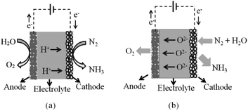
A solid-state electrocatalytic membrane reactor consists of a dense membrane electrolyte, porous anode and porous cathode. An oxide ion conducting membrane was first utilised for ammonia synthesis by Skodra and Stoukides.9 A ceramic membrane oxide ion conductor, YSZ, with Ru-based electrodes was investigated. Unfortunately, the ammonia formation rate was quite low either due to the poor electrical conductivity of the Ru-based electrode or due to the presence of water vapour, causing a poisoning effect on the catalyst. The main disadvantage of this oxide ion membrane reactor is the inconvenient stepwise process for separating the ammonia produced out of the non-utilised steam. This issue cannot be solved in the oxide ion membrane reactor, as water is needed at the cathode in order to produce hydrogen with oxide ions being transported to the anode. For proton conducting oxides, protons are transported through the electrolyte without humidifying the produced ammonia, see schematic in Fig. 2.High temperature proton conducting materials have wide application in solid oxide fuel cells, steam electrolysis and hydrogen separation.10–12 A good proton-conducting material with high protonic transport number at high temperatures is in high demand for practical application. Many perovskite oxides exhibit high proton conductivity after aliovalent doping and exposure to moisture.13 BaZrO3-based proton conductors are stable with high bulk conductivity but their total conductivity is usually low under normal sintering conditions.14 This could be attributed to the refractory nature of zirconates with low grain-growth rates that leads to a high grain boundary resistance.15 Although the sinterability of BaZr0.8Y0.2O3−δ can be improved significantly by introducing ZnO as a sintering aid at a temperature of 1325 °C, the total conductivity is often still not satisfactory even if the apparent grain boundary resistance is now negligible compared to the bulk.16 On the other hand, BaCeO3-based perovskite oxides typically exhibit much higher proton conductivity, yet have poor stability in the presence of CO2 and H2O, an unavoidable atmosphere in the applications such as fuel cells and steam electrolysers. Partially replacing cerium with zirconium in the perovskite structure has proved to improve stability and can avoid degradation. Therefore, a balance between high proton conductivity, good sinterability and stability can be realised by carefully manipulating the chemical compositions in the perovskite structure. In a previous communication, we optimised a BaCeO3-based proton conductor, BaCe0.5Zr0.3Y0.16Zn0.04O3−δ (BCZYZ), that can be easily sintered at 1300 °C with high proton conductivity and good stability.16
Protons generated at the anode from any hydrogen source can pass through the electrolyte and react with nitrogen at the cathode. The produced ammonia is easily separated from gaseous nitrogen by a condensation unit. Hence, proton conducting membrane reactors seem to be promising reactors for industrial ammonia synthesis.
For ammonia synthesis, the gaseous hydrogen or water is fed into the anode chamber where the gaseous nitrogen is flowed into the cathode chamber. When a current is imposed through the cell by the external power source, the protons from the anode start pumping through the membrane to the cathode. Murakami et al.17 suggested that the ammonia synthesis rate may not depend on only electrolysis potential. Other factors such as catalytic activity of electrode material, partial pressure of gaseous reactants, and temperature, are crucial parameters for the kinetics of ammonia synthesis.18,19 At atmospheric pressure, the decomposition of ammonia begins at about 450–500 °C. With the presence of catalyst, the decomposition starts at 300 °C and is nearly complete at 500–600 °C.20 The fact that the proton conductivity of the electrolyte increases with temperature leads to competition between the increase of H+ flux and the decrease in net NH3 formation rate due to thermal decomposition.
Typical operating temperatures of electrocatalytic ammonia synthesis via a cell with proton conducting solid oxide electrolyte is around 400–700 °C governed by the working temperature of the proton conductor electrolyte. A volcano-shape dependence of ammonia formation rates on temperature is observed in most cases. The formation rate of ammonia increases with temperature due to the increase of the H+ flux, then the formation rate reaches the maximum value at a certain temperature which varies between 450 and 650 °C depending on the experimental setup, proton conductivity of electrolyte, type of catalyst and partial pressure of the reactants. When the temperature is further increased, the ammonia formation rate then turns downhill due to the decomposition of ammonia becoming prominent. One of the highest formation rates of ammonia of 8 × 10⁻⁹ mol−1 cm−2 was reported by Liu et al.21
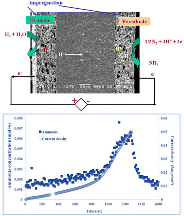
Fig. 3 shows a proton conducting electrolysis cell for ammonia production, based on barium cerium zirconate doped with yttrium and zinc, prepared by tape casting and impregnation. Ni is impregnated at the anode side and Fe at the cathode side, as in industrial ammonia synthesis. Ammonia production rate follows current flow. A maximum ammonia production rate of 4 × 10⁻⁹ mol−1 cm−2 at 450 °C was observed with a faradaic efficiency for ammonia production of 2.5%,22 with balanced hydrogen. Clearly there is a compromise between proton flux and ammonia decomposition, so the challenge is to reduce electrolyte thickness and improve low temperature electrocatalysis to allow facile ammonia production at lower temperatures.
Solid state electrochemical ammonia conversion
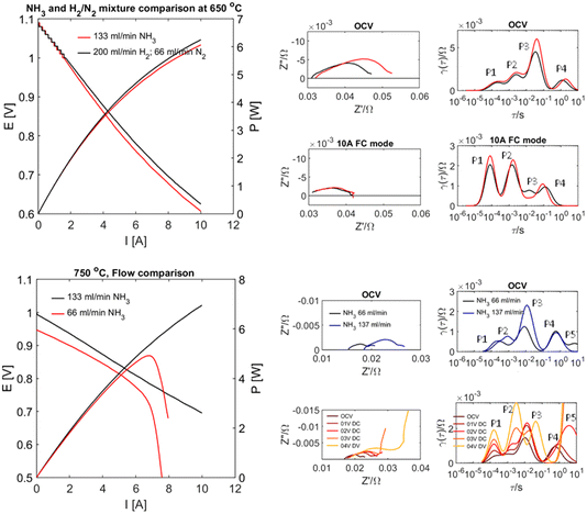
Whilst the above results highlight great challenges for electrochemical ammonia production, they also suggest effective performance in direct ammonia fuel cell mode. Recent results on proton conducting electrodes/electrolyte supports applied to direct ammonia fuel cells23 have shown this with complete conversion of ammonia. The performance of a tubular cell bundle with proton conductive BaCe0.7Zr0.1Y0.16Zn0.04O3−δ (BCZYZ) electrolyte, composite Ni/BaCe0.7Zr0.1Y0.16Zn0.04O3−δ (Ni/BCZYZ) fuel electrode and La0.8Sr0.2Co0.5Fe0.5O3−δ/BaCe0.7Zr0.1Y0.16Zn0.04O3−δ LSCF/BCZYZ oxygen electrode has been investigated under pure ammonia fuel. Single-cell testing with ∼36 cm2 electrode surface area was performed in both NH3 and the corresponding H2/N2 mix at 650–750 °C in pure NH3 using I–V and EIS techniques. The single-cell generated up to 7.7 W power density equal to 0.277 A cm−2 at 750 °C. Exhaust gases were analysed for conversion and cracking of NH3via gas chromatography both for OCV and under 10 A load between 650 and 750 °C, showing almost no ammonia emission in this temperature range, meaning that ammonia was almost entirely cracked to H2 and N2, Fig. 4.Hydride ion conductors
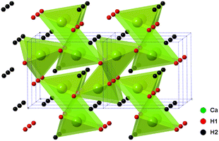
The alkaline earth hydrides (AeH2, with Ae = Ca, Sr and Ba) are a family of materials with potential in electrochemical and catalytic applications, including ammonia production and utilisation, not least due to the highly reducing nature of the hydride, H− ion. Their chemical simplicity may prove useful in understanding hydrogen mobility and exchange in a wider range of hydrogen storage materials also. Whilst they show good thermal stability (decomposition at temperatures >600 °C), they also show excellent reversibility, much better than most candidate hydrogen storage materials.In these studies, BaH2 (and similarly for Ca and Sr analogues) was prepared by the reaction of barium metal (99%, Sigma-Aldrich) with hydrogen gas. All manipulations were carried out in an argon filled glove box. The metal was cut and loaded in a molybdenum crucible, then loaded into the home-made reactor. The home-made reactor was made of stainless steel and has an inlet, outlet and bypass to allow the passage of different gases. The sealed reactor was taken out of the glove box and then transferred to a horizontal tube furnace. The reaction was performed under a continuous flow of hydrogen gas (95% H2 in 5% Ar) at 700 °C for 12 hours. As the barium metal is highly sensitive to moisture and air, the hydrogen gas was passed through an oxygen trap before entering the reactor. The resulting product was a crystalline sample of BaH2. A very small proportion of a BaO impurity was observed in the powder X-ray diffraction (PXRD) pattern. The orthorhombic Pnma structure of CaH2, BaH2 and SrH2 was first studied and reported by Zintl and Harder24 who described the metal ion arrangements as slightly distorted hexagonal close packing. The structure of CaH2 was later updated by Bergsma and Loopstra25 who determined the hydride/deuteride ion positions through neutron diffraction on hydride and deuteride samples. Andresen later modified the structure further still,26 with some modifications to the deuteride positions also using neutron diffraction. Peterson originally found a body centred cubic structure for BaH2,27 and reported a phase change at 580 °C. Bronger et al. later showed the structure to be the PbCl2Pnma using neutron diffraction, Fig. 5.28
The bulk conductivity of the CaH2 structure was found to reach 0.01 S cm−1 at 727 °C. SrH2 was also found to be in the same space group, with a conductivity of 0.01 S cm−1 attained at 557 °C.29 In a separate study, BaH2 was shown to have a high conductivity of 0.2 S cm−1 at 630 °C, with the BaH2 having undergone a phase transition from orthorhombic Pnma to hexagonal P63/mmc between 500 and 610 °C. It was shown that the primary conducting species was ionic in nature and likely to be the hydride ion from the sign and value of Nernst cell tests.30 Detailed studies have been performed utilising QENS to further confirm hydride mobility.31 It is unusual for a fast ion conductor to have a structure based upon a close-packed hexagonal lattice, important crystal chemical analogues such as Li2S are also of interest.
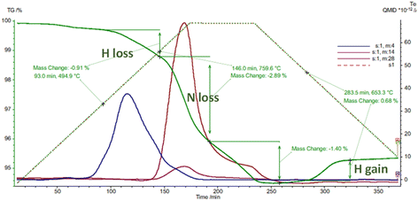
There seems to be facile incorporation of nitrogen into these lattices with hydrides, nitride hydrides imides and amides all having closely related lattices especially in terms of the metal ion locations. Thermogravimetric analysis confirms fast diffusion of different hydrogen isotopes and also nitrogen diffusion. The uptake and exchange of molecular nitrogen seems fairly facile suggesting clear opportunities for nitrogen activation. This is exemplified in thermal analysis studies in different atmospheres.
Fig. 6 shows loss of hydrogen and nitrogen followed by hydrogen uptake during thermal analysis cycling studies on a sample of mixed SrND/Sr2ND. In these hydride type lattices the hydrogen and nitrogen exchanges tend to follow certain patterns. When calcium or strontium hydrides are heated in nitrogen one sees nitrogen uptake at around 450 °C associated with hydrogen loss, at 600 °C further hydrogen is lost, with nitrogen and hydrogen loss at 730 °C. The temperatures where nitrogen uptake is observed (400–600 °C), correlate closely with those where facile hydrogen exchange is observed in isotopic studies. Hydrides lose hydrogen upon heating at temperatures increasing from 600 to 780 °C as the hydrogen content of the atmosphere is increased. Nitrogen–hydrogen compounds usually start to lose hydrogen at over 750 °C, without strong atmosphere dependence.
Fig. 7a and b show the changes in conductivity in BaH2 at 400 and 600 °C after exposure to 3% nitrogen/10% hydrogen in balance with argon gas for 3 minutes, conductivity was measured for approximately 30 minutes after every nitrogen dose. At 400 °C, the conductivity increases when the nitrogen gas is introduced. This may be due to an exothermic reaction, which increases the temperature when reacting with nitrogen gas, and so causes the conductivity to increase. After the nitrogen gas exposure, the conductivity then decreases. Fig. 7b shows that the conductivity at 600 °C decreases by 0.04 S cm−1 when nitrogen gas is introduced, unlike the reaction at 400 °C, it is endothermic.
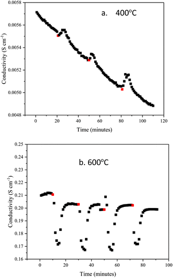 | ||
| Fig. 7 Change in BaH2 hydride ion conductivity after exposing to small doses of nitrogen gas at (a) 400 °C and (b) 600 °C. Red dots show the point of nitrogen gas introduction. | ||
Preliminary neutron diffraction studies on nitrogen uptake were also performed on starting compositions of BaD2 and CaD2. The starting CaD2Pnma phase accepted low level nitrogen doping onto deuterium sites, with a secondary phase, calcium nitride deuteride (Ca2ND, R![[3 with combining macron]](https://www.rsc.org/images/entities/char_0033_0304.gif) m), following. A drop in sample resistance in excess of one order of magnitude was observed during this experiment. The barium sample, on the other hand, demonstrated a 1 order of magnitude increase in resistance with some evidence for a change in carrier type from hydride.
m), following. A drop in sample resistance in excess of one order of magnitude was observed during this experiment. The barium sample, on the other hand, demonstrated a 1 order of magnitude increase in resistance with some evidence for a change in carrier type from hydride.
Conclusions
Hydrogen ion conductors have considerable potential for the conversion of ammonia. Utilisation of ammonia in protonic solid oxide fuel cells has proven to be highly successful; however, protonic oxides need to be developed as much thinner membranes to be usable in ammonia production without excessive losses. Hydride ion conductors are still difficult to apply due to fabrication and reactivity problems; however they exhibit facile nitrogen and hydrogen flux which is strongly enabling for ammonia production. Whilst nitride (N3−) and hydride (H−) are important species, they can intermingle, resulting in imide (NH2−) or even amide (NH2−) with these often existing as clusters within the lattice.32,33 There is a rather fluid interchange of apparent formal oxidation states in these nitrogen–hydrogen species during these changes that challenge conventional assumptions and lead the way to new chemistry that can drive reactions such as ammonia synthesis.Author contributions
JTSI has compiled these research findings based on the research studies of his co-workers who each performed the experimental studies.Conflicts of interest
There are no conflicts to declare.References
- https://www.globaldata.com/store/report/ammonia-market-analysis/, accessed February 2023.
- R. Lan, J. T. S. Irvine and S. W. Tao, Int. J. Hydrogen Energy, 2012, 37, 1482–1494 CrossRef CAS.
- G. R. Maxwell, Synthetic nitrogen products: a practical guide to the products and process, Kluwer Academic/Plenum Publishers, New York, 2014, pp. 163–198 Search PubMed.
- J. C. Ganley, J. H. Holbrook and D. E. McKinley, Solid State Ammonia Synthesis, NH3 fuel association, 2007, available from: https://nh3fuel.files.wordpress.com/2012/05/ssas_oct2007_final.pdf, accessed January 2023 Search PubMed.
- M. Itoh, K. I. Machida and G. Y. Adachi, Chem. Lett., 2000, 29, 1162–1163 CrossRef.
- M. IItoh, M. Saito, N. Tajima and K. Machida, Mater. Sci. Forum, 2007, 561–565, 1597–1600 Search PubMed.
- F. F. Li and S. Licht, Inorg. Chem., 2014, 53, 10042–10044 CrossRef CAS PubMed.
- G. J. Irvine and J. T. S. Irvine, Faraday Discuss., 2014, 53, 10042–10044 Search PubMed.
- A. Skodra and M. Stoukides, Solid State Ionics, 2009, 180, 1332–1336 CrossRef CAS.
- H. Iwahara, Solid State Ionics, 1996, 86–88, 9–15 CrossRef CAS.
- K. D. Kreuer, Solid State Ionics, 1997, 97, 1–15 CrossRef CAS.
- T. Norby, Solid State Ionics, 1999, 125, 1–11 CrossRef CAS.
- S. M. Haile, G. Staneff and K. H. Ryu, J. Mater. Sci., 2001, 36, 1149–1160 CrossRef CAS.
- S. B. C. Duval, P. Holtappels, U. F. Vogt, E. Pomjakushina, K. Conder, U. Stimming and T. Graule, Solid State Ionics, 2007, 178, 1437–1441 CrossRef CAS.
- S. W. Tao and J. T. S. Irvine, J. Solid State Chem., 2007, 180, 3493–3503 CrossRef CAS.
- S. W. Tao and J. T. S. Irvine, Adv. Mater., 2006, 18, 1581–1584 CrossRef CAS.
- T. Murakami, T. Nishikiori, T. Nohira and Y. Ito, J. Electrochem. Soc., 2005, 152(5), D75–D78 CrossRef CAS.
- G. Marnellos, S. Zisekas and M. Stoukides, J. Catal., 2000, 193, 80–87 CrossRef CAS.
- G. Marnellos and M. Stoukides, Science, 1998, 282, 98–100 CrossRef CAS PubMed.
- R. Kirk and D. Othmer, Encyclopedia of chemical technology, John Wiley & Sons. Inc, USA, 1985 Search PubMed.
- R. Q. Liu, Y. H. Xie, J. D. Wang, Z. J. Li and B. H. Wang, Solid State Ionics, 2006, 177, 73–76 CrossRef CAS.
- S. Klinsrisuk and J. T. S. Irvine, Catal. Today, 2017, 286, 41–50 CrossRef CAS.
- K. M. Nowicki, G. Carins, J. Bayne, C. Tupberg, G. J. Irvine and J. T. S. Irvine, J. Mater. Chem. A, 2023, 11, 352–363 RSC.
- E. Zintl and A. Harder, Z. Elektrochem. Angew. Phys. Chem., 1935, 41, 33–52 CrossRef CAS.
- J. Bergsma and B. O. Loopstra, Acta Crystallogr., 1962, 15, 92–93 CrossRef CAS.
- A. F. Andresen, A. J. Maeland and D. Slotfeldt-Ellingsen, J. Solid State Chem., 1977, 20, 93–101 CrossRef CAS.
- D. T. Peterson and M. Indig, J. Am. Chem. Soc., 1960, 82, 5645–5646 CrossRef CAS.
- W. Bronger, S. Chi-Chien and P. Müller, Z. Anorg. Allg. Chem., 1987, 545, 69–74 CrossRef CAS.
- M. C. Verbraeken, E. Suard and J. T. S. Irvine, J. Mater. Chem., 2009, 19, 2766–2770 RSC.
- M. C. Verbraeken, C. Cheung, E. Suard and J. T. S. Irvine, Nat. Mater., 2015, 14, 95–100 CrossRef CAS PubMed.
- G. J. Irvine, F. Demmel, H. Playford, G. M. Carins, M. Jones and J. T. S. Irvine, Chem. Mater., 2022, 34, 9934–9944 CrossRef CAS.
- T. Sichla, F. Altorfer and D. Hohlwein, et al. , Z. Anorg. Allg. Chem., 1997, 623, 414–422 CrossRef CAS.
- J. W. Makepeace, J. M. Brittain, A. S. Manghnani, C. A. Murray, T. J. Wood and W. I. F. David, Phys. Chem. Chem. Phys., 2021, 23, 15091–15100 RSC.
| This journal is © The Royal Society of Chemistry 2023 |

