 Open Access Article
Biomass-derived cellulose nanofibers and iron oxide-based nanohybrids for thermal insulation application†
Sourav
Sen
,
Ajit
Singh
,
Kamalakannan
Kailasam
 *,
Chandan
Bera
 * and
Sangita
Roy
 *
*
Institute of Nano Science and Technology Mohali, Knowledge City, Sector-81, Mohali-140306, Punjab, India. E-mail: kamal@inst.ac.in; chandan@inst.ac.in; sangita@inst.ac.in
First published on 25th July 2022
Abstract
In recent years, due to high energy consumption in the building sector and subsequent environmental issues, environment-friendly and cost-effective thermally insulating materials are in high demand to improve the energy efficiency of buildings. Current commercially available thermal insulating materials (polystyrene) always pose a challenge due to their non-biodegradability and poor insulating performance. To this end, biomass-derived aerogels are attracting significant interest as renewable and sustainable insulating materials. In this work, we have developed a facile strategy for synthesizing cellulose nanofibers from biomass-derived wood pulp as a cost-effective starting material by TEMPO-oxidation, and further incorporating iron oxide nanoparticles to make a nanohybrid. Interestingly, in these nanohybrids, the functional attributes like mechanical strength and flammability were improved to a great extent and thus overcoming the limitations of the commercially available thermal insulating materials in terms of their stability and durability. Most importantly, these nanohybrids demonstrated very low thermal conductivity, as low as 0.024 W m−1 K−1, indicating the better insulating potential of these nanohybrids as compared to other conventional insulating materials.
Introduction
In recent years, the increasing scarcity of non-renewable energy resources and the high energy consumption in industry and households for heating and cooling purposes have created high demands for renewable energy resources, as well as proper management of their usage. It has been observed that almost 10% of the total energy in the world is needed to maintain a pleasant atmosphere inside buildings.1 Hence, thermal insulation has been considered to play a crucial role in reducing energy consumption in the building sector. Already, different types of insulating materials are commercially available in the market, such as polystyrene,2 polyurethane3 and fiber glass4etc. However, they are not produced from natural resources and hence they are not eco-friendly, along with other limitations such as their non-biodegradable nature, limited durability and reduced thermal stability. Therefore, the use of environment-friendly and renewable insulating materials has attracted considerable attention from academic researchers, industries and government.5,6 Literature surveys have revealed that biopolymer-based renewable insulating materials such as cork7 and wood chips have been extensively used for thermal insulation applications before the introduction of cellulose-based smart materials, but their insulating performance is lower with thermal conductivities ranging between 0.040–0.050 W m−1 K−1 as compared to conventional insulating materials.2,3 Therefore, researchers need to look for another potential biopolymer-based insulating material.In this direction, cellulose has generated intense interest in recent years among the research community.8 At this point, it is worth mentioning that in the 1930s, Kistler was the first scientist who fabricated the aerogel, which is considered nowadays to be a highly promising material for various applications.9 Kistler considered cellulose and nitrocellulose for the first time to develop the aerogel, which was overlooked for several years. It was only in recent years that researchers were inclined to develop cellulose-based aerogels, keeping in mind the merits of this polymer,10 which can serve as a potential thermal insulator.11–13 Cellulose is the most abundant biomass available on earth. It is one of the next-generation biomaterials obtained from natural sources and thus can be utilized to develop cost-effective and environment-friendly insulating materials. The efficient utilization of renewable cellulose resources has the potential to develop sustainable products as alternatives to petroleum and mineral-based materials.14
Due to the unique porous structure of cellulose aerogel, it has many impressive properties such as low density, porosity, specific surface area,15 low thermal conductivity,16 low thermal expansion,17 biocompatibility and sustainability.18 Furthermore, it has been evident from the literature study that the flame retardant properties and high mechanical strength are challenging for biopolymer-based insulating materials. Recent research has shown that the mechanical strength and flame retardant properties of the organic polymer can be increased by the incorporation of different types of inorganic materials such as clays and graphenoids.19,20 The cellulose-based functional materials have been recenly reported by researchers for thermal insulation application. Canhui et al. developed flame retardant manganese hydroxide-based nanostructured cellulose for heat insulation application.21 Bergstrom et al. fabricated nanocellulose and graphene-oxide based flame retardant thermal insulators.11 Ning et al. synthesized cellulose nanocrystal and red mud-based functional materials for thermal and acoustic resistance.12 Huafeng et al. discussed butylene succinate and cellulose nanocrystal-based foam for thermal insulation application.22
In order to obtain improved mechanical strength and high specific surface area of cellulose aerogel, researchers have started to synthesize cellulose nanofibers (CNF) by TEMPO-oxidation. CNF has been recently used as a building material to fabricate CNF-based nanohybrids, which have demonstrated promising properties for various applications.23–30 There are several advantages in developing CNF-based nanohybrids as thermal insulation materials: (1) due to the nanofibrous structure of CNF, it may result in a high surface area that acts as a phonon barrier to prevent heat conduction.31 (2) CNF display organic functional groups on the surface, which can promote the modification of the CNF with different inorganic materials by different non-covalent interactions.32 In particular, CNF aerogels are gaining more interest as a class of natural biodegradable template, which consists of cross-linked three-dimensional (3D) architecture through the self-assembly of cellulose fibers as a result of strong hydrogen bonding interactions. This 3D interconnected architecture with plenty of pores in the aerogel allows the quick access and diffusion of molecules or ions within it, which makes the aerogels as the template for hosting various nanoparticles towards fabricating functional materials.
To date, only a few reports are available on the preparation of CNF aerogels that act as the functional matrix for the preparation of organic/inorganic hybrid composites by using various functional materials, such as SiO2,33 TiO234 and carbon nanotubes35 for various applications. Approaches to obtaining super insulating materials are possible by reducing the pore sizes of the CNF aerogel below the mean free path of air by incorporating nanoparticles.36 It is evident from the literature that cellulose and SiO2-based aerogels have been reported, where SiO2 was used to reduce the pore size of cellulose aerogel and enhance the Knudsen effect, thereby decreasing the thermal conductivity.37
The objective of this article is to fabricate environment-friendly, low-cost and sustainable thermal insulating materials from biomass-derived wood pulp combined with iron oxide nanoparticles (NPs). These newly developed thermally insulating organic–inorganic nanohybrids (iron oxide@CNF) may offer the additional advantages of high mechanical strength and flame retardant properties as compared to the other commercially available polymeric materials. In this article, we have utilized CNF from wood pulp, followed by TEMPO-oxidation to construct CNF and decorated CNF aerogel by the incorporation of iron oxide NPs.
In recent years, considerable efforts have been devoted to template-based methods for synthesizing nanohybrids with miscellaneous iron oxide (e.g., α-Fe2O3, γ-Fe2O3, Fe3O4).38,39 Surprisingly, none of these nanohybrids have been explored towards evaluating their thermal insulation performance. Hence, it is highly desirable to explore these novel nanohybrids for the development of futuristic thermal insulators for building sectors. Among these oxide materials, iron oxide NPs have attracted much attention because of their specific surface, biocompatibility and eco-friendly properties.39,40 To the best of our knowledge, this is the first report that demonstrates the exploration of CNF and iron oxide NPs-based organic/inorganic nanohybrids (iron oxide@CNF nanohybrid) towards the development of next-generation green technology-based materials with high mechanical strength, complemented by fire-retardant properties, and most importantly, these environment-friendly materials derived from natural sources displayed high thermal insulation. The thermal conductivity values achieved were significantly low in the range of 0.024–0.041 W m−1 K−1. The use of inorganic nanomaterials within this organic nanodomain was found to lower the thermal conductivity and thus enhancing the thermal insulation efficiency. This iron oxide@CNF nanohybrid is a highly efficient thermal insulator as compared to previously reported nanocellulose-based aerogels in terms of some essential important properties, i.e., mechanical strength, thermal insulation and fire retardancy.41,42 We envisage that these nanohybrid materials with improved material properties may serve as a potential next-generation building insulating material.
Material and methods
Materials and chemicals
Wood pulp was purchased from a private company that makes sanitary napkins at a very cost-effective rate (70/- rupees per kg) [Asian Agencies (Besite) Pvt. Ltd. Bangalore India]. 2,2,6,6-Tetramethylpiperidine-1-oxyl radical (TEMPO), FeCl3, FeCl2 and sodium hydroxide (NaOH) were purchased from Merck. Sodium hypochlorite (12%) and sodium bromide were purchased from TCI chemicals. All chemicals were of analytical grade and used without further purification.Fabrication of the CNF-based aerogel
Dried CNF was obtained through the TEMPO oxidation of wood pulp using a previously reported protocol.30 In this method, the aqueous solution of CNF and NaOH (25 mg NaOH per 100 mg of CNF) was stirred at 2–4 °C for 3 h to form a homogeneously dispersed solution of CNF (25 mg CNF per 1 ml water solution). This was followed by freezing the dispersed solution at −20 °C for 24 h to allow gelation. Following this, the frozen material was brought to room temperature and thawed, which resulted in the formation of the CNF hydrogel. After that, the CNF hydrogel was immersed in the deionized water and this immersion process was repeated several times by changing the surrounding deionized water until the complete removal of sodium hydroxide.44 The pH of the replaced water was checked and the washing process was continued until the pH became neutral. After multiple immersions of CNF hydrogel in the deionized water, the unreacted sodium hydroxide was removed from the crystalline cellulose hydrogel. Then CNF hydrogel was further frozen to make the CNF aerogel by the freeze–drying technique.Fabrication of the iron oxide@CNF nanohybrid by one-pot synthesis
Iron oxide NPs were synthesized by the co-precipitation method.43 CNF and iron oxide NPs-based nanohybrid materials were prepared through the addition of iron oxide NPs (2%, 5%, 7% and 10%) to the CNF dispersed solution at around pH-12. Here, we added CNF as wt% with respect to the amount of iron oxide NPs (w/w%). In the process of iron oxide@CNF-2%, 5%, 7% and 10% nanohybrid synthesis, we used 98, 95, 93 and 90 wt% of CNF with the corresponding amounts of iron oxide being 2, 5, 7 and 10 wt%, respectively (24.5 mg, 23.75 mg, 23.25 mg and 22.5 mg CNF was used per 1 ml of aqueous solution for the synthesis of iron oxide@CNF-2%, 5%, 7% and 10% nanohybrids respectively). The mixture was stirred for 2 hours, followed by freezing for 24 h to obtain inorganic hybrid hydrogels. To remove the excess sodium hydroxide, the CNF hydrogel was immersed in deionized water and this immersion process was repeated several times by changing the deionized water until the sodium hydroxide was completely washed out. The pH of the replaced water was checked until the pH became neutral. This was further freeze–dried to obtain the iron oxide@CNF nanohybrid (Fig. 1).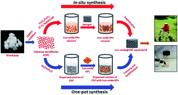 | ||
| Fig. 1 Schematic representation of the synthesis of the iron oxide@CNF nanohybrid by in situ and one-pot synthesis. | ||
Fabrication of the iron oxide@CNF nanohybrid by the in situ process
The CNF aerogel was immersed in a freshly prepared aqueous solution of FeCl3·4H2O and FeCl2 (20 ml) (molar ratio of [Fe3+/Fe2+] = 2) and the mixture was kept for 24 h.44 The hydrogel was placed in NaOH solution (1 M, 20 ml) and the colour of the sample immediately changed from yellow to black. The hydrogel was repeatedly rinsed with water as discussed to remove excess sodium hydroxide and the iron oxide@CNF nanohybrid was obtained after freeze–drying (Fig. 1).Determination of the carboxylate content
The amount of carboxylate contained in oxidized CNF was determined by classical conductometric titration.72 The oxidized CNF (0.05 g) were taken and suspended in 15 ml of 0.01 M hydrochloric acid solution, then the mixture was stirred for 10 min. After that, the suspension was titrated with 0.01 M NaOH. As shown in Fig. S4,† the titration curves indicated the presence of strong acid, corresponding to the excess of HCl and weak acid corresponding to the carboxyl content.The carboxyl group content (mmol g−1) was calculated using the following equation:72
| COOH (mmol g−1) = C(V2 − V1)/m |
Characterization
Fourier transform infrared spectroscopy
The Fourier transform infrared (FTIR) spectra were collected on an Agilent Cary 620 IR spectrophotometer for the CNF aerogel and the corresponding iron oxide@CNF nanohybrid material, which were placed between the two calcium fluoride discs and scanned between 4000 and 400 cm−1.X-ray diffraction analysis
The powdered sample was placed on a glass holder and the spectra were recorded in the 2θ range of 10° to 80° using a Bruker D8 Advance X-ray diffractometer equipped with a Cu Kα radiation source (λ = 1.541 Å) under the accelerating voltage of 40 kV.Raman spectroscopy
Raman spectra were acquired with a Renishaw Invia Raman microscope where the spectral shifts were obtained at ambient temperature with an argon ion excitation laser source at a fixed wavelength (785 nm). The Raman spectra were recorded over a spectral range (200 to 1800 cm−1) with a spectral resolution of 1.9286 cm−1. The measurements were done at an optimal power (1 mW) to prevent sample decomposition, 50× magnification, and 50 scans with a 10 s integration time.Mechanical strength analysis
Dynamic frequency sweep rheological analysis was conducted on an Anton Parr MCR302 rheometer using a 25 mm parallel plate geometry. The CNF aerogel and the corresponding iron oxide@CNF nanohybrid were demolded onto the lower plate of the rheometer just before the measurement, which enabled them to maintain their shape and size. The temperature was maintained at 25 °C throughout the measurement. The storage (G′) and loss (G′′) moduli of the hydrogels were recorded as a function of frequency between 0.1 and 16 Hz. To ensure that the measurements were made in the linear regime, an amplitude sweep was performed and the optimum strain value was obtained from the linear viscoelastic region. This protocol was previously reported for the biomolecular gels.45–47 The measurements were repeated three times to ensure reproducibility, with the average data shown.Field-emission scanning electron microscopy
The morphology and surface topology of the CNF aerogel and the corresponding iron oxide@CNF nanohybrid were determined by field-emission scanning electron microscopy (JEOL JSM-IT300, USA) at 15 kV with a probe current of 30 μA with different magnifications in various areas. The CNF aerogel and the corresponding nanohybrid were cast onto the silicon wafer after gelation at −20 °C. The sample was allowed to dry in the desiccator under vacuum. Samples were sputtered with gold for 60 s prior to imaging.Transmission electron microscopy
The transmission electron microscopy (TEM) samples were prepared by diluting iron oxide NPs in water and allowing 5 μL to adsorb on the TEM grid. The excess sample was wicked off using filter paper. The samples were then vacuum dried before imaging. The TEM micrographs were recorded with a JEOL JEM 2100 with a tungsten filament at an accelerating voltage of 200 kV.Thermal stability analysis
Thermogravimetric analysis was conducted using a DTG-60H (SHIMADZU) instrument to study the thermal stability of the CNF aerogel and the corresponding iron oxide@CNF nanohybrid in the temperature range of 30 to 600 °C at a heating rate of 10 °C min−1 in an argon atmosphere.N2-physisorption study
The N2-physisorption study was carried out using a Quantachrome Model Autosorb-iQ MP-XR-VP supplied by M s−1 Anton Paar India Pvt. Ltd. Surface area was determined by using the BET method, and the BJH method was used to determine the pore size distribution.Thermal conductivity measurement
The transient hot wire (THW) method has been used to measure the thermal conductivity of the CNF aerogel and iron oxide@CNF nanohybrid materials. The THW method is a well-established method for the precise thermal conductivity measurement of gases, nanofluids, and nanocomposites.48,49 This method is based on the principle of resistance thermometer detection (RTD). A platinum wire acts as the hot wire in the THW measurement setup to produce heat, as well as to sense the temperature in the test fluid or material. The constant current that passes through the infinite long wire produces a constant heat flux per unit length (q), which increases the temperature of the wire ΔT (t) as a function of time and is given by50 | (1) |
| R(t) = R0(1 + β(T(t) − T0)), | (2) |
The equation used for the thermal conductivity calculation of materials was derived using eqn (1) and (2) and is given as
 | (3) |
 is the slope of the linear part of the graph of ΔV as a function of ln(t).
Results and discussion
In this study, biomass-derived wood pulp has been used for the fabrication of CNF by the classical methodology of TEMPO-oxidation30 (Fig. 1). These CNF derivatives consist of a fiber-like morphology with an average diameter of 20–30 nm (Fig. S1†) as measured by AFM and DLS studies. In presence of the base, the nanofibrous network of CNF was dispersed in water and was further freeze-dried to construct the aerogel. By the co-precipitation method, we synthesized iron oxide NPs (mixture of Fe3O4 and γ-Fe2O3), which were monodispersed with their size being around 10–15 nm according to TEM and DLS studies (Fig. 2a, b and S3†). Very interestingly, it was observed that the iron oxide NPs were decorated on the surface of CNF irrespective of the in situ and one-pot synthesis. In the in situ process, the 3-D characteristics of the CNF aerogel allowed different types of guest molecules into its inner pores as fillers through non-covalent interactions. After the incorporation of iron oxide NPs into the CNF dispersed solution by one-pot synthesis, these iron oxide NPs were adsorbed onto the CNF fiber surface by electrostatic interactions (Fig. 2c). The overall surface charge density of CNF was negative and the relative potential of CNF was around −30 ± 3.2 mV, determined by zeta potential measurement (Fig S2 and Table S1†). The carboxylate group content in the oxidized CNF was around 0.62 mmol g−1 (Fig. S4†). Strong electrostatic interactions occur between the incorporated Fe2+/Fe3+ ions and CNF because the electron-rich oxygen atoms of the hydroxyl groups and negatively charged carboxyl groups of CNF are expected to interact with the electropositive transition metal cations, which stabilize these nanohybrids.44,71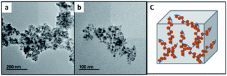 | ||
| Fig. 2 TEM images of iron oxide NPs (a and b) and a schematic representation of CNF and iron oxide NPs interaction in the 3-D nanohybrid architecture (c). | ||
Characterization of the iron oxide@CNF nanohybrids by XRD, FTIR and Raman spectroscopy
XRD analysis was carried out to investigate the formation of the iron oxide NPs-embedded CNF by in situ synthesis and the iron oxide@CNF nanohybrid by one-pot synthesis. The XRD pattern of CNF and the corresponding nanohybrids are shown in Fig. 3a. XRD showed the characteristic peaks at 15°, 22.5° and 34.5° corresponding to the crystallographic planes (101), (002) and (040) representing the characteristic peaks of CNF.53 The peaks of iron oxide@CNF nanohybrids at around 30.2°, 35.6°, 43.4°, 57° and 62.8° correspond to the crystallographic planes (002), (311), (400), (511) and (440), which are consistent with the JCPDS data for the mixture of iron oxide (γ-Fe2O3 and Fe3O4) NPs (JCPDS file no. 39-1346 for γ-Fe2O3 and 71-6336 for Fe3O4). The peak at 22.5° corresponding to the (002) plane further confirmed the presence of CNF in the iron oxide@CNF nanohybrid. However, other peaks at 15° and 34.5° for CNF disappeared, which could be due to the formation of intermediate phases in the presence of the highly alkaline solution of NaOH during the synthesis of the iron oxide@CNF nanohybrid, which was previously reported in the literature.53 These phases exhibited a low crystalline structure with weak diffraction peaks in the XRD pattern of the nanohybrid. Thus, the possible formation of the intermediate phases resulted in the disappearance of the characteristic peaks at 15° and 34.5° after the formation of nanohybrids.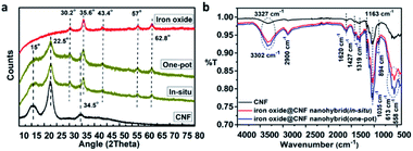 | ||
| Fig. 3 XRD (a) and FTIR-spectroscopy (b) of the iron oxide@CNF nanohybrids (by in situ and one-pot syntheses). | ||
The FTIR spectra as shown Fig. 3b, indicated the absorption band at 3327 cm−1 was related to the –OH stretching vibration and the band at 2900 cm−1 was due to the C–H asymmetric stretching and symmetric tensile vibration in the pyranoid ring.54 Another peak at 1620 cm−1 was attributed to the carboxylate or carboxylate group in their sodium salt form55–57 (Fig. S4†). The CNF aerogel showed the other characteristic peaks at 1427, 1319, 1163, 1035 and 894 cm−1 corresponding to the –CH2 bending, –CH2 wagging, –C–O–C asymmetric stretching of β-glycosidic linkage,58 and –C–O–C asymmetric bending of β-glycosidic linkage, respectively. The FTIR-spectra of the iron oxide@CNF nanohybrid comprising of two peaks at 558 cm−1 and 613 cm−1 indicated the Fe–O stretching vibration, which further proved the formation of iron oxide NPs59 (Fig. 3b). The broad band between 3015 cm−1-3650 cm−1 was assigned to the stretching frequency of hydroxyl groups, which shifted from 3332 cm−1 to the lower wavenumber 3307 cm−1, suggesting the strong interactions between the hydroxyl groups of cellulose and iron oxide NPs. From the above studies, it can be inferred that the iron oxide NPs were successfully formed by the in situ process and encapsulated in the 3D architecture of the cellulose aerogel through homogeneous dispersion via the aforementioned facile approach.
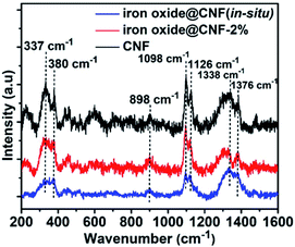
Furthermore, Raman spectroscopy showed characteristic Raman peaks at 337, 380, 898, 1098, 1126, 1338, and 1376 cm−1 (Fig. 4). Five different peaks at 337, 380, 898, 1098 and 1126 cm−1 correspond to the CCC, skeletal bending modes of COC, OCC and OCO, surface hydroxyl groups, C–OH bending at C-6 and C–O–C symmetric stretching and bending bands present in CNF, respectively. Another two peaks at 1338 cm−1 from HCH (wagging), HCC, HOC, COH (rocking) bending and at 1376 cm−1 are due to the HCH, HCC, HOC, COH bending.60 It has been observed that different peaks for CNF at 337, 380, 898, 1098, 1126, 1338, and 1376 cm−1 were gradually reduced after the incorporation of iron oxide NPs. Raman spectra also showed that after formation of the iron oxide@CNF nanohybrid, one peak at 380 cm−1 for surface hydroxyl groups disappeared and the presence of the peak at 898 cm−1 confirmed that the iron oxide NPs were mostly nucleated on the C–OH group at C-6.61
Thermal and mechanical properties of the iron oxide@CNF nanohybrid
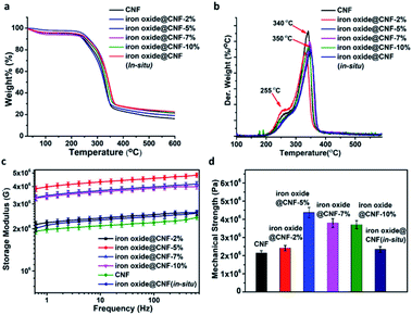
At this point, it is very important to know the thermal stability of the iron oxide@CNF nanohybrid for practical applications. TGA analysis indicated that for the iron oxide@CNF nanohybrids (by one-pot and in situ syntheses), two major weight loss peaks at around 50–100 °C and 245–340 °C were evident, irrespective of the doping percentage of iron oxide NPs. The former peak was attributed to the removal of the adsorbed moisture and the latter peak indicated the decomposition of cellulose. In this context, the decomposition temperature of the iron oxide@CNF nanohybrids was about 245–340 °C and there was no significant weight loss after the decomposition. The possible reason is that iron oxide NPs were present in the well-established 3-D network structure of the CNF aerogel, which in turn increased the stability of the nanohydrid.44 (Fig. 5a) However, the starting temperature of CNF decomposition in the iron oxide@CNF nanohybrid was higher as compared to the bare CNF aerogel. This indicated that the thermal stability of the iron oxide@CNF nanohybrid was enhanced after the incorporation of iron oxide NPs. From the TGA study, it was also observed that the char residue from the CNF aerogel was obtained after the full decomposition of CNF at a higher temperature and the char residue was found to be increased with the increasing percentage of iron oxide. The percentage of iron oxide nanoparticles (10 wt%) in the iron oxide@CNF-in situ nanohybrid was almost equal to the iron oxide@CNF-10% nanohybrid from the TGA study. From the dTG plot, it was observed that the depolymerization rate of the CNF aerogel at 340 °C was higher as compared to the CNF nanohybrid at 350 °C. This phenomenon is consistent with the earlier studies in the literature.62 Another small peak was observed at 255 °C, due to the water elimination from the CNF aerogel and the corresponding nanohybrid.The mechanical strength of the bare CNF aerogel and iron oxide@CNF nanohybrid is another essential parameter that is needed to be investigated in detail for their practical applicability. The rheology test was carried out to measure the storage modulus (G′) and mechanical strength of the iron oxide@CNF nanohybrid (by in situ synthesis and one-pot synthesis). The nanohybrid showed an enhancement of the storage modulus value, i.e. 2.1–4.2 MPa, which is higher than the storage modulus of normal CNF aerogel i.e. 1.85 MPa (Fig. 5b and c). This phenomenon was previously reported for other metal oxide based hybrid systems.33 Interestingly, it has been observed that the mechanical strength of the iron oxide@CNF nanohybrids gradually increased until 5 wt% doping of iron oxide NPs into the nanohybrid. Further, decrease in the mechanical strength was evident on increasing the doping percentage of iron oxide NPs into the nanohybrid. The possible reason behind this differential mechanical strength could be that the iron oxide nanoparticles were homogeneously distributed at a certain doping ratio of iron oxide NPs in the CNF nanohybrid (till 5 wt% of iron oxide NPs). On further increasing the doping ratio of iron oxide NPs, the NPs were not homogeneously distributed in the CNF nanohybrid, which destabilized the overall structure of the nanohybrid. In this context, FESEM-EDX line scanning analysis was performed across the surface of the iron oxide@CNF nanohybrid to observe the distribution of iron oxide NPs along the surface of the nanohybrid (Fig. S5†) From this study, it has been observed that the iron oxide line profile for the iron oxide@CNF-5% nanohybrid is uniform as compared to the iron oxide line profile of iron oxide@CNF-7% & 10% nanohybrids, which confirmed the homogeneous distribution of iron oxide nanoparticles along the surface of the iron oxide@CNF-5% nanohybrid. This result further confirmed that the distribution of iron oxide NPs became relatively inhomogeneous when the wt% percentage of iron oxide NPs is increased beyond 5% in the nanohybrid. For, this reason, the mechanical strength of iron oxide@CNF-7% is lower than the iron oxide@CNF-5% nanohybrid and it is almost same as the iron oxide@CNF-10% nanohybrid.63 For the one-pot synthesis, it is worth mentioning that 15 wt% of iron oxide NPs is the possible upper limit for NPs to form a stable nanohybrid. After that, the nanohybrid (20 wt% of iron oxide) was destabilized at the time of washing (Fig. S6†).
Morphological characterization of the iron oxide@CNF nanohybrid aerogel
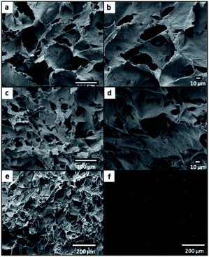
The morphological analysis has revealed that the CNF aerogel and CNF-based nanohybrids were in monolithic condition and the structure was found to be macroporous (Fig. 6a–d). From the FESEM images, the pure CNF aerogel exhibited a sheet-like assembled structure with a high degree of disorder and the sheets were interconnected (Fig. 6a and b). The iron oxide@CNF nanohybrids with different amounts of iron oxide NPs showed a similar morphology to that of the pure CNF-based aerogel (Fig. 6c and d). From the mapping of the corresponding FESEM image of the iron oxide@CNF nanohybrid, it was confirmed that the Fe element was distributed on the surface of the cross-section of the iron oxide@CNF nanohybrid (Fig. 6e and f). Therefore, it was concluded that the iron oxide NPs were distributed in the iron oxide@CNF nanohybrid.The apparent density of the foams, ρ foam was calculated based on eqn (4) using the measured weight (m) and volume (V) of the foams. The mass was measured by using a high-precision analytical balance and the apparent volume was calculated by measuring the dimensions of the samples using a calliper.
| ρ = m/V | (4) |
The densities of the pure CNF aerogel and iron oxide@CNF nanohybrids were measured in the range of 0.030 to 0.037 g cm−3. The pores of the nanohybrids were in the micron range with very dense walls comprised of self-assembled CNF.64 However, the pore size and distribution were quite different in the CNF and iron oxide@CNF nanohybrids (Fig. S7†) As expected, N2-physisorption study revealed that the BET surface areas of the iron oxide@CNF-nanohybrids (density 0.032–0.037 g cm−3) were lower as compared to the CNF aerogel (density 0.030 g cm−3)63 (Fig. S8†). This indicates that the void volume has been decreased within the nanohybrids due to the thickening of the dense pore walls of the nanohybrids after the incorporation of iron oxide NPs.65 The surface areas of CNF and the CNF nanohybrids were around 5–22 m2 g−1 and the pore volumes were around 0.017–0.051 cm3 g−1, indicating the macroporous structure of the CNF aerogel and nanohybrids64 (Table S2†).
Thermal conductivity measurement
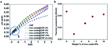
The thermal conductivity of the CNF, iron oxide@CNF nanohybrids by one-pot and in situ synthesis have been measured by the transient hot-wire method at around 30 °C. The slope of the linear portion of the plot ΔV vs. ln(t) through eqn (3) for each sample was considered for the thermal conductivity calculation as shown in Fig. 7a.We observed the linear portion S in the ΔV vs. ln(t) graph for all the samples. Different thermal conductivities, k, corresponding to different slopes S represent the characteristics of the microstructure.66 We observed that the thermal conductivity, k, of the CNF, iron oxide@CNF nanohybrids by one-pot (2, 5, 7 and 10% iron oxide NPs) and iron oxide@CNF nanohybrid by in situ are in the range 0.024–0.043 W m−1 K−1 (Table 1). The above results indicated a very low thermal conductivity, as low as 0.0245 W m−1 K−1 for iron oxide@CNF-2%, which is lower than the air thermal conductivity at room temperature (Fig. 7b) (see the ESI for more detail (Fig. S9†)).
| Samples | Thermal conductivity values (W m−1 K−1) |
|---|---|
| CNF | 0.0436 ± 0.0003 |
| Iron oxide@CNF-2% | 0.0245 ± 0.0001 |
| Iron oxide@CNF-5% | 0.0336 ± 0.0003 |
| Iron oxide@CNF-7% | 0.0393 ± 0.0003 |
| Iron oxide@CNF-10% | 0.041 ± 0.0003 |
| Iron oxide@CNF (in situ) | 0.0312 ± 0.0002 |
The possible reason for this observed low thermal conductivity is the introduction of more fibril–fibril interactions, which provide increased thermal resistance due to the dense pore walls in the assembled CNF. Thus, the dense pore walls of micron-sized pores are more effective for decreasing the thermal conductivity of the CNF nanohybrid as compared to the Knudsen effect for nanoscale porous aerogel materials.64 CNF heat conduction through CNF was reduced due to phonon surface scattering from the CNF aerogel, which resulted in the decrease in the overall thermal conductivity of the nanohybrid (Fig. 8). From the simple kinetic heat conduction model, kc = 1/3Cvvλ, where kc is the heat conductivity, Cv is the heat capacity, v is velocity and λ is the mean free path of phonons.67 The reported values of Cv and v are 1.212 J K−1 g−1 and 2973 m S−1, respectively, for bulk cellulose.68,69 Using λ, since the cellulose nanofiber diameter was around 20 nm, kc = 0.024 W m−1 K−1 (thermal conductivity only by heat conductivity). This value still suggests greater thermal conductivity than the experimentally obtained value for the iron oxide@CNF-2% nanohybrid. Hence, it can be concluded that the dense walls in the assembled CNF play a crucial role in reducing both the thermal conduction and convection of the nanohybrid. It is also to be noted that the thermal conductivity increased with the increasing wt% of iron oxide (5, 7, 10 wt%) NPs. The thermal conductivity of porous aerogel materials depends on three parameters, namely, solid thermal conductivity, gaseous thermal conductivity, and radiation thermal conductivity.75 It is possible that the iron oxide nanoparticles take part as a contributor to solid conduction after a certain limit (2 wt% of iron oxide nanoparticles), which results in the increased thermal conductivity of the CNF-based nanohybrids (5, 7 and 10 wt%). In this context, it is worth mentioning that the iron oxide has a thermal conductivity of 0.58 W m−1 K−1.76 Hence, greater than 2% of the iron oxide NPs doping in CNF may have contributed to the enhancement in the conductivity.
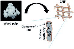 | ||
| Fig. 8 Schematic representation of phonon surface scattering onto the surface of CNF in the iron oxide@CNF nanohybrid. | ||
Fire retardant property
Earlier literature has clearly revealed that any type of polymeric insulation material is easily ignitable and, therefore, fire retardants must be incorporated into these materials to improve the flame retardancy.19,70 Recent work has shown that the flame retardancy of polymeric materials can be improved by the addition of different inorganic components such as clay, graphenoids and inorganic nanoparticles.19,20 The fire retardancy was assessed by the standardized UL 94 vertical burning test.11 In the current study, iron oxide NPs were incorporated into the CNF aerogel, which can lead to an improvement in the flame retardancy of the iron oxide@CNF nanohybrid.73,74To analyse the flame retardancy property of iron oxide@CNF nanohybrids, a series of combustion tests were undertaken based on the horizontal flame test. Fig. 9 shows the conditions of the CNF aerogel and CNF nanohybrids with different proportions of iron oxide NPs after ignition with flame. It was observed that the CNF aerogel was almost completely burnt, while other iron oxide@CNF nanohybrids showed fire retardancy to a greater extent. This indicates that the iron oxide NPs have a large influence on the fire retardancy of the iron oxide@CNF nanohybrid.
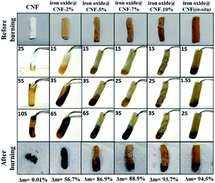 | ||
| Fig. 9 Digital photos of the horizontal flame testing of the CNF aerogel and iron oxide@CNF nanohybrids (Δm = residual weight after burning). | ||
Conclusions
In this study, we have used biomass-derived wood pulp to develop iron oxide@CNF nanohybrids for application in thermal insulation. Iron oxide NPs were judiciously incorporated into the CNF aerogel to increase the mechanical strength of the nanohybrid from 1.85 MPa to 4.2 MPa and enhance the flame retardant property. After the incorporation of iron oxide NPs into the CNF aerogel, the size of the pores decreased, resulting in a very low thermal conductivity of 0.024 W m−1 K−1, which is lower as compared to the traditional thermal insulating materials polystyrene and mineral wool. Also, the thermal conductivity of the nanohybrid is lower than the air thermal conductivity at room temperature. This nanohybrid based insulating material obtained from a renewable resource is cost-effective and environment-friendly. These initial results provide sustainable motivation to augment the use of renewable thermal insulating material for applications in smart buildings.Author contributions
Sourav Sen: writing – original draft preparation, investigation, methodology. Ajit Singh: investigation. Kamalakannan Kailasam: conceptualization, investigation, writing-reviewing and editing, funding acquisition, supervision. Chandan Bera: conceptualization, investigation, writing-reviewing and editing. Sangita Roy: conceptualization, investigation, writing-reviewing and editing, funding acquisition, supervision.Conflicts of interest
There are no conflicts to declare.Acknowledgements
The authors acknowledge the Department of Science and Technology, India (TMD/CERI/BEE/2016/082) for providing the financial support. Mr Sourav Sen thank INST Mohali, India for providing the doctoral fellowship.References
- H. C. Ong, T. M. I. Mahlia and H. H. Masjuki, Renewable Sustainable Energy Rev., 2011, 15, 639–647 CrossRef.
- K. T. Yucel, C. Basyigit and C. Ozel, presented in part at the 15th Symposium in Thermophysical Properties, 2003 Search PubMed.
- J. K. Lee, G. L. Gould and W. Rhine, J. Sol-Gel Sci. Technol., 2009, 49, 209–220 CrossRef CAS.
- M. Koebel, A. Rigacci and P. Achard, J. Sol-Gel Sci. Technol., 2012, 63, 315–339 CrossRef CAS.
- Y. Habibi, Chem. Soc. Rev., 2014, 43, 1519–1542 RSC.
- Y.-Y. Li, B. Wang, M.-G. Ma and B. Wang, Int. J. Polym. Sci., 2018, 2018, 8973643 Search PubMed.
- N. Hüsing and U. Schubert, Angew. Chem., Int. Ed., 1998, 37, 22–45 CrossRef.
- A. L. Volynskii and N. F. Bakeev, Russ. Chem. Bull., 2005, 54, 1–15 CrossRef CAS.
- S. S. Kistler, Nature, 1931, 127, 741 CrossRef CAS.
- E. I. Akpan, B. Wetzel and K. Friedrich, Green Chem., 2021, 23, 2198–2232 RSC.
- B. Wicklein, A. Kocjan, G. Salazar-Alvarez, F. Carosio, G. Camino, M. Antonietti and L. Bergström, Nat. Nanotechnol., 2015, 10, 277–283 CrossRef CAS PubMed.
- G. Zhu, H. Xu, A. Dufresne and N. Lin, ACS Sustainable Chem. Eng., 2018, 6, 7168–7180 CrossRef CAS.
- J. Zhou and Y.-L. Hsieh, Nano Energy, 2020, 68, 104305 CrossRef CAS.
- B. E. Dale, J. Chem. Technol. Biotechnol., 2003, 78, 1093–1103 CrossRef CAS.
- N. Lavoine and L. Bergström, J. Mater. Chem. A, 2017, 5, 16105–16117 RSC.
- K. Uetani and K. Hatori, Sci. Technol. Adv. Mater., 2017, 18, 877–892 CrossRef CAS PubMed.
- F. Carosio, J. Kochumalayil, F. Cuttica, G. Camino and L. Berglund, ACS Appl. Mater. Interfaces, 2015, 7, 5847–5856 CrossRef CAS PubMed.
- D. Klemm, B. Heublein, H.-P. Fink and A. Bohn, Angew. Chem., Int. Ed., 2005, 44, 3358–3393 CrossRef CAS PubMed.
- T. Kashiwagi, F. Du, J. F. Douglas, K. I. Winey, R. H. Harris and J. R. Shields, Nat. Mater., 2005, 4, 928–933 CrossRef CAS PubMed.
- H. D. Wagner, Nat. Nanotechnol., 2007, 2, 742–744 CrossRef CAS PubMed.
- Y. Han, X. Zhang, X. Wu and C. Lu, ACS Sustainable Chem. Eng., 2015, 3, 1853–1859 CrossRef CAS.
- D. Yin, J. Mi, H. Zhou, X. Wang and H. Tian, Carbohydr. Polym., 2020, 247, 116708 CrossRef CAS PubMed.
- F. Jiang and Y.-L. Hsieh, J. Mater. Chem. A, 2014, 2, 6337–6342 RSC.
- F. Jiang, H. Liu, Y. Li, Y. Kuang, X. Xu, C. Chen, H. Huang, C. Jia, X. Zhao, E. Hitz, Y. Zhou, R. Yang, L. Cui and L. Hu, ACS Appl. Mater. Interfaces, 2018, 10, 1104–1112 CrossRef CAS PubMed.
- K. Uetani, S. Izakura, H. Koga and M. Nogi, Nanoscale Adv., 2020, 3, 1024–1030 RSC.
- G. Patterson and Y.-L. Hsieh, Nanoscale Adv., 2020, 12, 5623–5634 RSC.
- J. Song, C. Chen, Z. Yang, Y. Kuang, T. Li, Y. Li, H. Huang, I. Kierzewski, B. Liu, S. He, T. Gao, S. U. Yuruker, A. Gong, B. Yang and L. Hu, ACS Nano, 2018, 12, 140–147 CrossRef CAS PubMed.
- P. K. Sachdeva, S. Gupta and C. Bera, Nanoscale Adv., 2021, 11, 3279–3287 RSC.
- C. Dore, J. Osmond and A. Mihi, Nanoscale, 2018, 37, 17884–17892 RSC.
- V. K. Pal, R. Jain, S. Sen, K. Kailasam and S. Roy, Cellulose, 2021, 28, 10335–10357 CrossRef CAS.
- S. Q. Zeng, A. Hunt and R. Greif, J. Heat Transfer, 1995, 117, 1055–1058 CrossRef CAS.
- L. Heux, G. Chauve and C. Bonini, Langmuir, 2000, 16, 8210–8212 CrossRef CAS.
- J. Cai, S. Liu, J. Feng, S. Kimura, M. Wada, S. Kuga and L. Zhang, Angew. Chem., Int. Ed., 2012, 51, 2076–2079 CrossRef CAS PubMed.
- Y. Lu, Q. F. Sun, J. Li and Y. X. Liu, Key Eng. Mater., 2014, 609–610, 542–546 Search PubMed.
- H. Qi, J. Liu, J. Pionteck, P. Pötschke and E. Mäder, Sens. Actuators, B, 2015, 213, 20–26 CrossRef CAS.
- B. P. Jelle, Energy and Buildings, 2011, 43, 2549–2563 CrossRef.
- A. Demilecamps, C. Beauger, C. Hildenbrand, A. Rigacci and T. Budtova, Carbohydr. Polym., 2015, 122, 293–300 CrossRef CAS PubMed.
- Z. Sun, H. Yuan, Z. Liu, B. Han and X. Zhang, Adv. Mater., 2005, 17, 2993–2997 CrossRef CAS.
- X. Yu, S. Tong, M. Ge, J. Zuo, C. Cao and W. Song, J. Mater. Chem. A, 2013, 1, 959–965 RSC.
- S. Laurent, D. Forge, M. Port, A. Roch, C. Robic, L. Vander Elst and R. N. Muller, Chem. Rev., 2008, 108, 2064–2110 CrossRef CAS PubMed.
- J. Qi, Y. Xie, H. Liang, Y. Wang, T. Ge, Y. Song, M. Wang, Q. Li, H. Yu, Z. Fan, S. Liu, Q. Wang, Y. Liu, J. Li, P. Lu and W. Chen, ACS Sustainable Chem. Eng., 2019, 7, 9202–9210 CrossRef CAS.
- K. Kriechbaum, V. Apostolopoulou-Kalkavoura, P. Munier and L. Bergström, ACS Sustainable Chem. Eng., 2020, 8, 17408–17416 CrossRef CAS PubMed.
- W. Wu, Q. He and C. Jiang, Nanoscale Res. Lett., 2008, 3, 397 CrossRef CAS PubMed.
- C. Wan and J. Li, ACS Sustainable Chem. Eng., 2015, 3, 2142–2152 CrossRef CAS.
- R. Jain, G. Khandelwal and S. Roy, Langmuir, 2019, 35, 5878–5889 CrossRef CAS PubMed.
- H. Kaur, R. Jain and S. Roy, ACS Appl. Mater. Interfaces, 2020, 12, 52445–52456 CrossRef CAS PubMed.
- P. Sharma, H. Kaur and S. Roy, Biomacromolecules, 2019, 20, 2610–2624 CrossRef CAS PubMed.
- D. Cabaleiro, J. Nimo, M. J. Pastoriza-Gallego, M. M. Piñeiro, J. L. Legido and L. Lugo, J. Chem. Thermodyn., 2015, 83, 67–76 CrossRef CAS.
- A. Singh, R. Lenin, N. K. Bari, C. Bakli and C. Bera, Nanoscale Adv., 2020, 8, 3507–3513 RSC.
- J. Xu and B. Yu, J. Phys. D: Appl. Phys., 2008, 41, 139801 CrossRef.
- J. K. Ludwig Michalski, M. Joseph, K. Eckersdorf and K. Eckerdorf, Temperature Measurement, 2001 Search PubMed.
- S. Sen, T. Pan and P. Ghosal, Measurement, 2011, 44, 842–846 CrossRef.
- C. Tian, S. Fu and L. A. Lucia, Cellulose, 2015, 4, 2571–2587 CrossRef.
- S. Y. Oh, D. I. Yoo, Y. Shin, H. C. Kim, H. Y. Kim, Y. S. Chung, W. H. Park and J. H. Youk, Carbohydr. Res., 2005, 340, 2376–2391 CrossRef CAS PubMed.
- A. de Lima Pizi Cândido, N. F. Fregonezi, A. J. F. Carvalho, E. Trovatti and F. A. Resende, J. Bionanosci., 2020, 3, 766–772 CrossRef.
- T. Saito, S. Kimura, Y. Nishiyama and A. Isogai, Biomacromolecules, 2007, 8, 2485–2491 CrossRef CAS PubMed.
- S. Coseri, B. Gabriela, F. Z. Lidija, S. S. Jasna, T. L. Per, S. Simona, K. Tatjana, N. Ali and L. Tom, RSC Adv., 2015, 104, 85889–85897 RSC.
- X. F. Sun, R. C. Sun, J. Tomkinson and M. S. Baird, Polym. Degrad. Stab., 2004, 83, 47–57 CrossRef CAS.
- D. Wang, Y. Li, Q. Wang and T. Wang, J. Solid State Electrochem., 2012, 16, 2095–2102 CrossRef CAS.
- M. Szymańska-Chargot, J. Cybulska and A. Zdunek, Sensors, 2011, 11, 5543–5560 CrossRef PubMed.
- M. A. Legodi and D. de Waal, Dyes Pigm., 2007, 74, 161–168 CrossRef CAS.
- B. Wicklein, D. Kocjan, F. Carosio, G. Camino and L. Bergström, Chem. Mater., 2016, 7, 1985–1989 CrossRef.
- C. Aulin, J. Netrval, L. Wågberg and T. Lindström, Soft Matter, 2010, 14, 3298–3305 RSC.
- K. Sakai, Y. Kobayashi, T. Saito and A. Isogai, Sci. Rep., 2016, 6, 20434 CrossRef PubMed.
- Z. Zhang, G. Sèbe, D. Rentsch, T. Zimmermann and P. Tingaut, Chem. Mater., 2014, 8, 2659–2668 CrossRef.
- B. Merckx, P. Dudoignon, J. P. Garnier and D. Marchand, Adv. Civ. Eng., 2012, 625395 Search PubMed.
- K. Sato, Y. Tominaga and Y. Imai, Nanomaterials, 2020, 10 CAS.
- A. V. Blokhin, O. V. Voitkevich, G. J. Kabo, Y. U. Paulechka, M. V. Shishonok, A. G. Kabo and V. V. Simirsky, J. Chem. Eng. Data, 2011, 56, 3523–3531 CrossRef CAS.
- I. Diddens, B. Murphy, M. Krisch and M. Müller, Macromolecules, 2008, 41, 9755–9759 CrossRef CAS.
- A. Dasari, Z.-Z. Yu, G. Cai and Y. W. Mai, Prog. Polym. Sci., 2013, 38, 1357–1387 CrossRef CAS.
- T. Philippe, T. Zimmermann and G. Sèbe, J. Mater. Chem., 2012, 38, 20105–20111 Search PubMed.
- D. da Silva Perez, S. Montanari and M. R. Vignon, Biomacromolecules, 2003, 4.5, 1417–1425 CrossRef PubMed.
- L. Zhang, Q. Wang, R. K. Jian and D. Y. Wang, J. Mater. Chem. A, 2020, 8.5, 2529–2538 RSC.
- J. Zhang, Q. Kong and D. Y. Wang, J. Mater. Chem. A, 2018, 6.15, 6376–6386 RSC.
- X. Lu, R. Caps, J. Fricke, C. T. Alviso and R. W. Pekala, J. Non-Cryst. Solids, 1995, 188.3, 226–234 CrossRef.
- J. Shackelford and W. Alexander, CRC Materials Science and Engineering Handbook, CRC press: 2000 Search PubMed.
Footnote |
| † Electronic supplementary information (ESI) available. See https://doi.org/10.1039/d2na00010e |
| This journal is © The Royal Society of Chemistry 2022 |

