 Open Access Article
Investigation of K-ion storage performances in a bismuth sulfide-carbon nanotube composite anode†
Jang-Yeon Hwang a,
Rudra Kumarb,
Hee Min Kimb,
Muhammad Hilmy Alfaruqi
 a,
JaeKook Kim
 a and
Yang-Kook Sun
 *b
*b
aDepartment of Materials Science and Engineering, Chonnam National University, Gwangju, 61186, Republic of Korea
bDepartment of Energy Engineering, Hanyang University, Seoul, 04763, Republic of Korea. E-mail: yksun@hanyang.ac.kr
First published on 12th February 2020
Abstract
Herein, we synthesize a nanostructured bismuth sulfide/carbon nanotube composite and demonstrate its potential use as a high-capacity anode for K-ion batteries, for the first time. The composite anode shows reversible K-ion storage capabilities that are supported by density functional theory calculations.
K-ion batteries (KIBs) have attracted attention as a promising alternative to commercial Li-ion batteries (LIBs) because of their low cost, earth abundance, and low redox potential (Li: −3.04 V and K: −2.93 V vs. standard hydrogen electrode), along with the similar chemical properties between K and Li.1 KIBs also possess an electrical energy storage mechanism similar to LIBs, which has accelerated the development of KIBs.2
To date, alloys of group 14 or 15 elements in the periodic table, as defined by their corresponding alloying reactions, have been considered as potential candidates for high-capacity anodes in KIBs.3 Owing to the large volume changes of the alloying anode in the K-system (along with the issue of the large ionic size of K+ ion (1.38 Å)),4 most alloying anodes have been designed and synthesized via structural modulation with carbon-conducting agents, which are very important for buffering volume strain as well as creating pathways for electrical conduction.5–9 McCulloch et al. investigated the electrochemical behavior of Sb–C composite electrodes as KIB anode.10 Through the formation of cubic K3Sb phase, the Sb–C composite electrode delivered a high reversible capacity of 650 mA h g−1. Sultana et al. confirmed the alloying–dealloying reaction between Sn and K by forming the K2Sn5 and K4Sn23 compound.11 Recently, Huang et al. determined the potassium-storage mechanism in Bi.12 In the K3Bi–K3Bi2–KBi2–Bi dealloying–alloying mechanism, the Bi electrode delivers high potassium storage capacity of 400 mA h g−1. On the basis of conversion and sequential alloying–dealloying reactions, SnS2–rGO and Sb2S–graphene composite electrodes delivered high reversible capacities as KIB anode.13,14 On the other hand, in the previously reported LIB and sodium-ion battery (SIB) system, bismuth sulfide (Bi2S3) was also considered a potential electrode material for high capacity and low-cost electrode materials; however, their development is still infancy.15–17 In addition, to the best of our knowledge, K-storage capability in Bi2S3 has not yet been reported. Herein, we synthesize nanostructured Bi2S3 carbon nanotube (CNT) composites and investigate their possible electrochemical K-ion storage behaviors in KIBs for the first time.
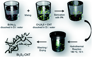
The nanostructured Bi2S3 and Bi2S3-CNT composite was synthesized via one-step hydrothermal method. The synthesis details are illustrated in Fig. 1. In a typical process, Bi(NO3)3 was first dissolved in deionized (D.I.) water and mixed with CH4N2S. For the composite anode, to disperse the CNTs in the solution, isopropyl alcohol was added with ultrasonication for 15 min. Then, it was directly transferred to a Teflon-sealed stainless steel autoclave and held at 180 °C for 10 h. The resultant powder was washed with ethanol and D.I. water, and the final products were obtained after drying at 80 °C overnight. The structure of the as-prepared Bi2S3 and Bi2S3-CNT composite powder was confirmed using X-ray diffraction (PANalytical, Empyrean) with a Cu-Kα radiation source (λ = 1.5418 Å). To prepare composite electrodes, the Bi2S3-CNT powder, acetylene black, and poly(vinylidene fluoride) were mixed with N-methyl pyrrolidone at a ratio of 8![[thin space (1/6-em)]](https://www.rsc.org/images/entities/char_2009.gif) :
:![[thin space (1/6-em)]](https://www.rsc.org/images/entities/char_2009.gif) 1
1![[thin space (1/6-em)]](https://www.rsc.org/images/entities/char_2009.gif) :
:![[thin space (1/6-em)]](https://www.rsc.org/images/entities/char_2009.gif) 1 by weight. The obtained slurry was pasted on the copper foil as a current collector and dried without air exposure at 80 °C.
1 by weight. The obtained slurry was pasted on the copper foil as a current collector and dried without air exposure at 80 °C.
To confirm the morphological properties and elemental distributions in the composite material, scanning electron microscopy (SEM) and transmission electron microscopy (TEM) with energy dispersive X-ray (EDX) mapping were conducted, respectively. The electrochemical behavior was examined in R2032-type coin cells with K metal as the counter electrode (CE) filled with 1 M mol dm−3 KFSI ethylene carbonate![[thin space (1/6-em)]](https://www.rsc.org/images/entities/char_2009.gif) :
:![[thin space (1/6-em)]](https://www.rsc.org/images/entities/char_2009.gif) diethyl carbonate (1
diethyl carbonate (1![[thin space (1/6-em)]](https://www.rsc.org/images/entities/char_2009.gif) :
:![[thin space (1/6-em)]](https://www.rsc.org/images/entities/char_2009.gif) 1 v/v) solution at room temperature. For comparison, bare Bi2S3 sample was also synthesized and characterized via same procedures.
1 v/v) solution at room temperature. For comparison, bare Bi2S3 sample was also synthesized and characterized via same procedures.
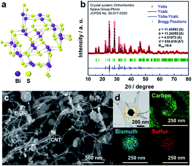
Fig. 2a shows the typical orthorhombic structure of Bi2S3 with Pbnm symmetry. Fig. 2b reveals the Rietveld refinement of the high-resolution XRD pattern of the Bi2S3 composite (JCPDS no. 00-017-0320). The Rietveld refinement of the XRD pattern of Bi2S3-CNTs yielded lattice parameters a, b, and c of 11.45592, 11.24392, and 4.01072 Å, respectively. The accuracy of the structural model obtained by Rietveld refinement was confirmed by the small reliability factors (Rwp: 16.6%). In addition to Bi2S3, the Bi2S3-CNT composite showed a pure orthorhombic structure belonging to the Pbnm space group without any impurities and secondary phase (Fig. S1†). The weight content of CNTs in the composite was determined to be ∼10.2 wt% according to thermogravimetric analysis, as shown in Fig. S2.† We characterized the Bi2S3-CNT composite by SEM and TEM. As seen in Fig. 2c (SEM image), spherical Bi2S3 nanoparticles in the range 70–100 nm are highly interconnected through a web of CNTs that ensure the flow of electrons. TEM and EDX mapping of the Bi2S3-CNT composite clearly reveal the existence of carbon, bismuth, and sulfur element in the composite.
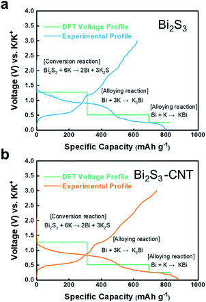
Fig. 3a shows that the predicted voltage curves using first-principles calculation overlap with the first charge–discharge voltage profile of the Bi2S3 electrode in the voltage range 0.01–3.0 V.
In previous reports on LIB and SIBs,15,16 Bi2S3 typically undergoes subsequent conversion and alloying reactions during the charge–discharge process. On the basis of those reaction mechanisms, we first predicted that the electrochemical reaction of Bi2S3 in KIB is likely proceeds as follows:
| Bi2S3 + 6K → 2Bi + 3K2S | (1) |
| Bi + 3K → K3Bi | (2) |
| Bi + K → KBi | (3) |
In the first reaction step, Bi2S3 reacts with K to form metallic Bi and potassium sulfide. Then, metallic Bi and K react to form the K–Bi alloy compounds K3Bi and KBi. Note that the discharge products of Bi, K2S, K3Bi, and KBi were selected based on stable species presence in the calculated phase diagrams of K–Bi–S ternary and K–Bi binary systems, which were obtained from Materials Projects.18,19 Through the conversion and alloying reaction, the theoretical capacity of eqn (1), (2), and (3) were calculated as 312, 384, and 145 mA h g−1, respectively. To validate our proposed mechanism, we performed voltage calculations using the two-phase coexistence method.20 Our predicted theoretical voltages for the reactions Bi2S3 + 6K → 2Bi + 3K2S, Bi + 3K → K3Bi, and Bi + K → KBi were 1.28, 0.51, and 0.25 V, respectively. As seen in Fig. 3, the Bi2S3 electrode delivered a high discharge–charge (potassiation–depotassiation) capacity of 820 and 650 mA h g−1, respectively. The calculated voltages are in good agreement with experimental voltage profiles of Bi2S3 anode. The calculated capacity values in each potassiation step were nearly identical to those obtained from density functional theory (DFT) calculations. The calculation methods are provided in the ESI.†21–23 The Bi2S3-CNT composite electrode delivered much higher discharge–charge capacity of 900 mA h g−1 and 750 mA h g−1, respectively (see Fig. 3b). It should be noted that the irreversible capacity over the theoretical value during the potassiation step was mainly attributed to the formation of a solid-electrolyte interphase layer induced by CNTs.24 As observed in SEM and TEM images, the interconnected CNT network in the composite provides effective conductive paths for rapid electron transport, which are likely to assist K+ ion storage in Bi2S3. In general, conversion-alloying-based electrodes are known to deliver high capacities but experience severe volume changes owing to the continuous self-pulverization of electrode materials during the electrochemical charge–discharge reaction. This phenomenon was observed in the Bi2S3 electrode upon cycling in LIBs,11 which resulted in capacity degradation with prolonged cycles. In the case of KIB, our DFT calculations (Fig. 4) suggest that in the first stage, Bi2S3 formed the K2S phase with unit cell volume of 403.74 Å3. Further potassiation led to the formation of K3Bi from metallic Bi with unit cell volume of 361.38 Å3, followed by the formation of KBi phase in the final stage. This calculation revealed the high volume expansion of the Bi2S3 electrode in the KIB system. Such large volume changes often accelerate electrode damage, which leads to the loss of electrical contact, and subsequently rapid capacity fading.
 | ||
| Fig. 4 Electrochemical K storage mechanism of Bi2S3 in the composite electrode and volume changes. The insets show the detailed crystalline parameters computed by DFT. | ||
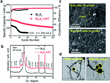
Fig. 5a shows the cycle life test of Bi2S3 and Bi2S3-CNT electrodes in the voltage range 0.01–3.0 V at 200 mA g−1. While Bi2S3 only delivered a charge capacity of 250 mA h g−1 because of the sluggish kinetics of K-ions with Bi2S3, the capacity reached 450 mA h g−1 for the Bi2S3-CNT composite electrode. After 10 cycles, the Bi2S3 electrode showed a drastic capacity loss; after 20 cycles, it had very limited capacity. Moreover, after the first few cycles, the CE of above 98% was stabilized for the Bi2S3-CNT composite electrode, while the CE for the Bi2S3 electrode was much worse; this corresponds to the typical trend of capacity decay in the cycling stability test for the two electrodes. The sudden capacity decay of the Bi2S3 electrode is mainly attributed to the huge volume changes during repeated charge–discharge process observed in the DFT calculation results in Fig. 4. In contrast, the CNT encapsulants provided a strong buffer effect that mitigated the large volume changes and pulverizations of Bi2S3 particles upon cycling, and enabled more efficient electronic conduction of the whole electrode during cycling. As a result, the Bi2S3-CNT electrode demonstrated much better cycling stability over 50 cycles. The electro-conducting CNT matrix enhances the electric conductivity of Bi2S3 and thus has been effective in overcoming the poor potassium intercalation ability in Bi2S3. To determine the correlation between the electrochemical performance and structural durability of these electrode materials, XRD, SEM, and TEM analyses were carried out with cycled (after 20 cycles) Bi2S3 and Bi2S3-CNT composite electrodes. As expected from the different cycling stability between the two electrodes, the Bi2S3 electrode experienced severe structural damage after cycling. A noticeable broadening of the XRD peaks for the Bi2S3 electrode relative to the Bi2S3-CNT composite electrode was observed (Fig. 5b). The Bi2S3-CNT composite electrode retained its original crystal structure after cycling, while an amorphous phase was found in the cycled Bi2S3 electrode. As seen in SEM images (Fig. 5c), the cycled Bi2S3 electrode had extensive cracking on the surface, whereas the cycled Bi2S3-CNT electrode exhibited no signs of cracking. TEM examination of the Bi2S3-CNT electrode between before and after cycling further revealed that CNTs play an important role in suppressing the periodic volume expansion of Bi2S3 during cycling (Fig. 5d).25 Although the Bi2S3 particles in the composite experienced large volume changes between before and after 20 cycles, Bi2S3 nanoparticles were well encapsulated within the CNT matrix. The CNT encapsulants provided a strong buffer effect that mitigated the large volume changes and pulverizations of Bi2S3 particles upon cycling, and enabled more efficient electronic conduction of the whole electrode during cycling. Compare to the Bi2S3 electrode, the Bi2S3-CNT electrode showed the much lower resistances after cycling; this clearly explain that CNT plays an important role to improve electronic conductivity and fast K+ ion diffusion kinetics (Fig. S3†). The XRD, SEM, TEM and EIS results clearly demonstrate the superior structural stability of the Bi2S3-CNT composite and its enhanced electrochemical K-storage performance.
In summary, we demonstrated the potential use of Bi2S3-CNT as anode material for KIBs. A combination of experimental and first-principles calculations was used to investigate the overall K-storage mechanism of Bi2S3. The CNT matrix in this composite anode not only provides electronic conductivity but also decreases the absolute stress/strain, and accommodates a period of large volume changes during the potassiation–depotassiation process. As a result, the Bi2S3-CNT delivered high capacity and good cycling stability. We hope that this study provides insight on the design of new electrode materials and contributes toward the realization of KIBs as a sustainable next-generation battery.
Conflicts of interest
There are no conflicts to declare.Acknowledgements
This work was supported by the National Research Foundation of Korea grant funded by the Korea Government Ministry of Education and Science Technology (NRF-2018R1A2B3008794) and (NRF-2018R1A5A 1025224) and (NRF-2019R1F1A1063538).Notes and references
- J.-Y. Hwang, S.-T. Myung and Y.-K. Sun, Adv. Funct. Mater., 2018, 2, 182938 Search PubMed.
- K. Kubota, M. Dahbi, T. Hosaka, H. Kumakura and S. Komaba, Chem. Rec., 2018, 18, 459–479 CrossRef CAS PubMed.
- W. Zhang, W. K. Pang, V. Sencadas and Z. Guo, Joule, 2018, 2, 1534–1547 CrossRef CAS.
- Q. Zhang, J. Mao, W. K. Pang, T. Zheng, V. Sencadas, Y. Chen, Y. Liu and Z. Guo, Adv. Energy Mater., 2018, 8, 1703288 CrossRef.
- W. Zang, J. Mao, S. Li, Z. Chen and Z. Guo, J. Am. Chem. Soc., 2017, 139, 3316 CrossRef PubMed.
- Z. Ma, T. Li, Y. L. Huang, J. Liu, Y. Zhou and D. Xue, RSC Adv., 2013, 3, 7398–7402 RSC.
- Z. S. Ma, Z. C. Xie, Y. Wang, P. P. Zhang, Y. Pan, Y. C. Zhou and C. Lu, J. Power Sources, 2015, 290, 114–122 CrossRef CAS.
- C. Wang, Z. Ma, Y. Wang and C. Lu, J. Electrochem. Soc., 2016, 163, A1157–A1163 CrossRef CAS.
- Z. Ma, Z. Xie, Y. Wang and C. Lu, Scr. Mater., 2017, 127, 33–36 CrossRef CAS.
- W. D. McCulloch, X. Ren, M. Yu, Z. Huang and Y. Wu, ACS Appl. Mater. Interfaces, 2015, 7, 26158 CrossRef CAS.
- I. Sultana, M. Rahman, T. Ramireddy, Y. Chen and A. Glushenkov, J. Mater. Chem. A, 2017, 5, 23506 RSC.
- J. Huang, X. Lin, H. Tan and B. Zhang, Adv. Energy Mater., 2018, 8, 1703496 CrossRef.
- V. Lakshmi, Y. Chen, A. A. Mikhaylov, A. G. Medvedev, I. Sultana, M. Rahman, O. Lev, P. V. Prikhodchenko and A. M. Glushenkov, Chem. Commun., 2017, 53, 8272 RSC.
- Y. Lu and J. Chen, Sci. China: Chem., 2017, 60, 1533 CrossRef CAS.
- L. Zhao, H.-H. Wu, C. Yang, Q. Zhang, G. Zhong, Z. Zheng, H. Chen, J. Wang, K. he, B. Wnag, T. Zhu, X. C. Zeng, M. Liu and M.-S. Wang, ACS Nano, 2018, 12, 12597–12611 CrossRef CAS.
- W. Yang, H. Wnag, T. Liu and L. Gao, Mater. Lett., 2016, 167, 102–105 CrossRef CAS.
- B. Long, Z. Qiao, J. Zhang, S. Zhang, M. S. Balogun, J. Lu, S. Song and Y. Tong, J. Mater. Chem. A, 2019, 7, 11370–11378 RSC.
- S. P. Ong, L. Wang, B. kang and G. Ceder, Chem. Mater., 2008, 20(5), 1798–1807 CrossRef CAS.
- A. Jain, G. Hautier, S. P. Ong, C. J. Moore, C. C. Fischer, K. A. Persson and G. Ceder, Phys. Rev. B: Condens. Matter Mater. Phys., 2011, 84, 045115 CrossRef.
- I. A. Courtney, J. S. Tse, O. Mao, J. Hafner and J. R. Dhan, Phys. Rev. B: Condens. Matter Mater. Phys., 1998, 58, 15583 CrossRef CAS.
- P. Giannozzi, et al., J. Phys.: Condens. Matter, 2009, 21, 395502 CrossRef.
- J. P. Perdew, A. Ruzsinszky, G. I. Csonka, O. A. Vydrov, G. E. Scuseria, L. A. Constantin, X. Zhou and K. Burke, Phys. Rev. Lett., 100, 136406 CrossRef.
- K. Momma and F. Izumi, J. Appl. Crystallogr., 2011, 44, 1272 CrossRef CAS.
- J.-Y. Hwang, S.-T. Myung, J.-H. Lee, A. Abouimrane, I. Belharouak and Y.-K. Sun, Nano Energy, 2015, 16, 218–226 CrossRef CAS.
- J. Ni, Y. Zhao, T. Liu, H. Zheng, L. Gao, C. Yan and L. Li, Adv. Energy Mater., 2014, 1400798 CrossRef.
Footnote |
| † Electronic supplementary information (ESI) available. See DOI: 10.1039/d0ra00374c |
| This journal is © The Royal Society of Chemistry 2020 |


