 Open Access Article
Highly efficient planar heterojunction perovskite solar cells with sequentially dip-coated deposited perovskite layers from a non-halide aqueous lead precursor†
Muhammad Adnana and
Jae Kwan Lee *b
*b
aDepartment of Chemistry, Graduate School, Chosun University, Gwangju, 61452, Republic of Korea
bDepartment of Chemistry Education, Chosun University, Gwangju, 61452, Republic of Korea. E-mail: chemedujk@chosun.ac.kr; Fax: +82 62 232 8122; Tel: +82 62 230 7319
First published on 3rd February 2020
Abstract
High-performance planar heterojunction (PHJ) perovskite solar cells (PrSCs) with MAPbI3 perovskite films were fabricated using a facile, environmentally benign, efficient and low-cost dip-coating deposition approach on a bilayered ZnO/TiO2 electron transport system from aqueous non-halide Pb(NO3)2. Outstanding performance of PrSCs was achieved due to the PHJ configuration of FTO/TiO2/ZnO/MAPbI3/spiro-OMeTAD/MoO3/Ag. These PHJ PrSCs exhibited better performance and stability with thinner ZnO layers in contrast to those with mesoporous TiO2 scaffolds, indicating that the thickness of the ZnO layer in the PHJ architecture significantly affected the surface coverage, morphology, crystallinity, and stability of the MAPbI3 perovskite films processed by dip-coating deposition.
1. Introduction
Organic–inorganic lead halide perovskite solar cells (PrSCs) have received significant attention because of their excellent breakthrough power conversion efficiencies (PCEs), making them potential alternatives to the conventional silicon-based solar cells.1–10 Over the past few years, extensive efforts with respect to efficient fabrication methods for perovskite material layers in PrSCs have been devoted for improving the coverage, crystallinity, and uniformity of the perovskite materials. These include various strategies such as sequential deposition from the spin-casting of a lead source followed by a reaction with alkylammonium halide by dipping in a solution, spin-casting, or vacuum deposition,2–15 direct spin-casting of a perovskite precursor solution with an adduct, thermal annealing, interfacial engineering, solvent engineering, or processing-additive treatment16–25 to provide promising high PCEs of PrSCs. Moreover, numerous device architectures have been investigated with various mesoscopic14 or planar heterojunction (PHJ)12 configurations and their inverted types15 to enhance the feasibility of using PrSCs as well as their PCEs. Among them, in the mesoscopic configuration of PrSCs, the presence of a mesoporous TiO2 (mp-TiO2) scaffold for the perovskites can increase the interfacial surface area between the perovskite material and the electron transporting materials. This enables the effective transport of electrons towards the transparent conductive oxide (TCO) from the perovskite absorber, resulting in the highest PCE of approximately 22% reported so far.11 However, these fabricated PrSCs frequently possess small active areas and suffer from substrate size limitations during spin-casting. Therefore, it is challenging yet essential for commercial applications to develop inexpensive manufacturing processes that facilitate the formation of large-area perovskite films via efficient routes including doctor-blade methods and inkjet or roll-to-roll printing.1,25–29Very recently, we reported an efficient approach for fabricating a large-area perovskite film via successive deposition based on simple sequential dip-coating (SDC) using an aqueous non-halide lead precursor solution in a mesoscopic PrSC architecture.26 The non-halide lead precursor has recently attracted interest to avoid toxic high-polarity aprotic organic solvents such as dimethylformamide, which are typically used owing to the poor solubility of lead halides. Pb(NO3)2 was used as the non-halide lead precursor because of its compatibility with environmentally benign and low-cost non-toxic solvents such as water.3 It is likely to adsorb much better on the surface of ZnO than on the surface of mp-TiO2 in aqueous solutions, leading to stable and efficient (CH3NH3)PbI3 (MAPbI3) perovskite crystals by several SDC and successive solid-state ion-exchange and reaction (SSIER) repetitions with CH3NH3I (MAI). This SDC and SSIER approach might facilitate the production of large-area perovskite films using non-halide lead precursors in an aqueous solution. However, the mp-TiO2 scaffolds have also restricted the development of flexible devices due to their high process temperature of above 450 °C and the prominent hysteresis phenomenon in PrSCs devices.16–18 Meanwhile, the PHJ architecture of PrSCs might be more favorable because of several merits such as the unique simple structure and lower thermal processing, negligible hysteresis effects, and comparable performance with mesoscopic PrSCs.21,22 Therefore, in this study, we have attempted to improve the performance of PHJ PrSCs using a sequential dip-coating-processed perovskite film on ZnO covering compact TiO2 (c-TiO2) as a bilayer electron transporting layer (ETL) without the mp-TiO2 scaffolds. Interestingly, we have found that the performances of the PHJ PrSCs fabricated using this approach are significantly affected by the thickness of ZnO deposited on the c-TiO2 layer.33,34
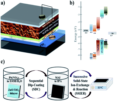
Herein, we report high-performance PHJ PrSCs with perovskite films fabricated using a facile, environmentally benign, efficient and low-cost dip-coating deposition approach on thin ZnO/c-TiO2 bilayer ETL from aqueous non-halide Pb(NO3)2. The outstanding performance of PrSCs was achieved due to the PHJ configuration of FTO/c-TiO2/ZnO/MAPbI3/spiro-OMeTAD/MoO3/Ag. Notably, PHJ MAPbI3 perovskite films fabricated on thinner ZnO Layers exhibited better performance and stability with a notable PCE of 12.17% and this value is comparable with our previously reported mp-TiO2 scaffolds MAPbI3 perovskite films having PCE of 12.41%, respectively. Fig. 1 shows the (a) PHJ PrSC structure, (b) energy level diagram, and (c) preparation of the MAPbI3 perovskite films by sequentially dip-coating a ZnO-covered c-TiO2/FTO substrate in aqueous Pb(NO3)2 and MAI solutions.
2. Experimental section
2.1 Materials
MAPbI3 was prepared according to the method reported previously.26 All the solvents were purchased from Sigma-Aldrich, TCI, and Alfa Aesar and were purified using appropriate methods. The MAPbI3 precursor solution was prepared under a nitrogen atmosphere. 2,2′,7,7′-Tetrakis(N,N-di-4-methoxyphenylamino)-9,9′-spirobifluorene (spiro-OMeTAD) was obtained from Solaronix. The ZnO sol–gel was synthesized by reacting zinc acetate dihydrate (1.6 g, Sigma Aldrich, 99.9%), ethanolamine (0.5 g, Sigma Aldrich, 99.5%) and 2-methoxy-ethanol (10 mL, Sigma Aldrich, 99.8%) for 4 h at room temperature.302.2 Measurements and instruments
The absorption spectra were recorded on a PerkinElmer Lambda 2S ultraviolet (UV)-visible spectrometer. The surface morphologies were imaged using a field emission scanning electron microscopy (FESEM, Nova Nano-SEM 450, FEI, Netherlands) system. The crystallinities of the MAPbI3 perovskite layers were investigated using X-ray diffraction (XRD, D/Max2500 V/PC, Rigaku Corp, Japan). The solar cell efficiencies were characterized under simulated 100 mW cm−1 AM 1.5G irradiation from a Xe arc lamp with an AM 1.5 global filter. The simulator irradiance was characterized using a calibrated spectrometer; the illumination intensity was set using a silicon diode with an integrated KG1 optical filter certified by the National Renewable Energy Laboratory (NREL). The spectral mismatch factors were calculated to be less than 5% for each device. The short circuit currents were also found to be within 5% of the values calculated using the integrated external quantum efficiency (EQE) spectra and the solar spectrum. The applied potential and cell currents were measured using a Keithley 2400 model digital source meter. The J–V curves were measured at a voltage setting time of 100 ms. The EQEs were measured by under-filling the device area using a reflective microscope objective to focus the light output from a 75 W Xe lamp, monochromator, and optical chopper; the photocurrent was measured using a lock-in amplifier and the absolute photon flux was determined using a calibrated silicon photodiode and recorded for 5 s per point (80 points) from 350 to 900 nm. In the J–V curve hysteresis tests, a forward scan implies measuring the sweeping voltage from the short circuit to the forward bias, while a backward scan implies sweeping in the opposite direction. To explore the active area of the device and to avoid the scattering effects from the edges, a non-reflective metal plate mask with an aperture of 4.5 mm2 was used for the solar cells.2.3 Fabrication of MAPbI3 perovskite films
To fabricate the MAPbI3 perovskite films from aqueous Pb(NO3)2, we employed a novel SSIER approach reported previously. In a typical process, a metal oxide-coated FTO substrate was first dipped into a 0.1 M solution of Pb(NO3)2 (Sigma-Aldrich, 99.9%) dissolved in ethanol/water (2![[thin space (1/6-em)]](https://www.rsc.org/images/entities/char_2009.gif) :
:![[thin space (1/6-em)]](https://www.rsc.org/images/entities/char_2009.gif) 1, v/v) for approximately 30 s. The substrate was washed using deionized (DI) water and ethanol and then annealed at 120 °C for 10 min, resulting in a highly transparent film over the substrate. Subsequently, the substrate was dipped into 0.1 M MAI in isopropanol (Sigma-Aldrich, 99.5%) for 30 s, washed with chloroform and diethyl ether (Sigma-Aldrich, >96%) and annealed at 80 °C for 10 min. The above procedure constituted one SSIER cycle. After the chosen number of SSIER repetitions, these films were exposed for 600 s to the MAI solution, followed by annealing at 80 °C for 10 min. In addition to the above SSIER approach, the SDC process was performed. In the first cycle of the SDC process, the metal oxide-coated FTO substrates were dipped into a 0.1 M solution of Pb(NO3)2 dissolved in ethanol/water (2
1, v/v) for approximately 30 s. The substrate was washed using deionized (DI) water and ethanol and then annealed at 120 °C for 10 min, resulting in a highly transparent film over the substrate. Subsequently, the substrate was dipped into 0.1 M MAI in isopropanol (Sigma-Aldrich, 99.5%) for 30 s, washed with chloroform and diethyl ether (Sigma-Aldrich, >96%) and annealed at 80 °C for 10 min. The above procedure constituted one SSIER cycle. After the chosen number of SSIER repetitions, these films were exposed for 600 s to the MAI solution, followed by annealing at 80 °C for 10 min. In addition to the above SSIER approach, the SDC process was performed. In the first cycle of the SDC process, the metal oxide-coated FTO substrates were dipped into a 0.1 M solution of Pb(NO3)2 dissolved in ethanol/water (2![[thin space (1/6-em)]](https://www.rsc.org/images/entities/char_2009.gif) :
:![[thin space (1/6-em)]](https://www.rsc.org/images/entities/char_2009.gif) 1, v/v) for approximately 30 s, washed using pure water and ethanol, and annealed at 120 °C for 10 min. The Pb(NO3)2 layer-coated substrate was dipped into the MAI solution for 30 s, followed by annealing at 80 °C for 10 min. The above procedure formed one SDC cycle. After the designated number of repetitions of the SDC cycle, the SSIER process was employed to provide a better MAPbI3 perovskite film.
1, v/v) for approximately 30 s, washed using pure water and ethanol, and annealed at 120 °C for 10 min. The Pb(NO3)2 layer-coated substrate was dipped into the MAI solution for 30 s, followed by annealing at 80 °C for 10 min. The above procedure formed one SDC cycle. After the designated number of repetitions of the SDC cycle, the SSIER process was employed to provide a better MAPbI3 perovskite film.
2.4 PrSC device fabrication
An FTO-coated glass substrate was patterned and etched with Zn powder and 2 M HCl in DI water. Subsequently, the substrates were cleaned with a detergent, rinsed with DI water and ethanol, and then dried under an N2 gas stream. The c-TiO2 layer was spin-cast on the substrate with a titanium(IV) diisopropoxide bis(acetylacetonate) solution diluted in butanol (1![[thin space (1/6-em)]](https://www.rsc.org/images/entities/char_2009.gif) :
:![[thin space (1/6-em)]](https://www.rsc.org/images/entities/char_2009.gif) 10, v/v) and then annealed at 450 °C for 1 h. Over the c-TiO2 layer, the ZnO layer was spin-cast from ZnO sol–gel solutions, which were prepared with various concentrations (0.75 M, 0.38 M, 0.25 M and 0.19 M) of zinc acetate dehydrate at 5000 rpm for 30 s followed by annealing at 300 °C for 1 h. MAPbI3 layers were fabricated according to the aforementioned method. Spiro-OMeTAD as the hole-transporting material (HTM) was deposited via spin-coating at 3000 rpm for 30 s. The solution was prepared by dissolving 29 mg of spiro-OMeTAD, 7 μL of 170 mg mL−1 lithium bis(trifluoromethanesulfonyl)imide (Li-TFSI) in acetonitrile, and 11 μL of 4-tert-butylpyridine (t-BPy). Finally, device fabrication was completed by the thermal evaporation of a thin MoO3 layer and a thick Ag layer on the HTM film under reduced pressure (less than 10−6 torr).
10, v/v) and then annealed at 450 °C for 1 h. Over the c-TiO2 layer, the ZnO layer was spin-cast from ZnO sol–gel solutions, which were prepared with various concentrations (0.75 M, 0.38 M, 0.25 M and 0.19 M) of zinc acetate dehydrate at 5000 rpm for 30 s followed by annealing at 300 °C for 1 h. MAPbI3 layers were fabricated according to the aforementioned method. Spiro-OMeTAD as the hole-transporting material (HTM) was deposited via spin-coating at 3000 rpm for 30 s. The solution was prepared by dissolving 29 mg of spiro-OMeTAD, 7 μL of 170 mg mL−1 lithium bis(trifluoromethanesulfonyl)imide (Li-TFSI) in acetonitrile, and 11 μL of 4-tert-butylpyridine (t-BPy). Finally, device fabrication was completed by the thermal evaporation of a thin MoO3 layer and a thick Ag layer on the HTM film under reduced pressure (less than 10−6 torr).
3. Results and discussion
3.1 MAPbI3 perovskite film characteristics
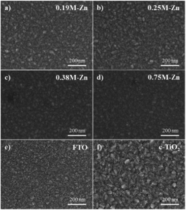
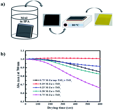
For the PHJ architecture of PrSCs via the SDC process, we found that the performances of the devices were significantly affected by the thickness of the ZnO layer covering the c-TiO2 layer. In this study, the thin ZnO layers were prepared by spin-casting ZnO sol–gel solutions over the c-TiO2 layer at 5000 rpm for 40 s, followed by annealing at 300 °C for 1 h. The thickness of these layers was controlled by varying the Zn concentrations. Fig. 2 shows the SEM images of the surface morphologies of the thin ZnO layers fabricated from ZnO sol–gel precursors prepared with the respective Zn concentrations (a–d) over the c-TiO2 layer compared to those of the (e) bare FTO substrate and (f) c-TiO2 layer deposited on FTO. The corresponding AFM surface roughness images are shown in Fig. S1 of the ESI.† As we could not define the thickness of these ZnO layers because of the non-uniform and rough c-TiO2 layer dominated by the FTO substrate, we determined the thickness indirectly using the surface roughness observed from AFM surface profiling. The spin-cast c-TiO2 layer had a rather smooth surface with a root-mean square (rms) value of 26.35 nm compared to that (37.15 nm) of bare FTO with good surface coverage but with some pinhole-shaped defects (Fig. 2e, f, S1e and f†). Meanwhile, as shown in Fig. 2a–d and S1a–d,† the specific thicknesses and surface morphologies of the ZnO layers deposited on c-TiO2 are significantly affected by the Zn concentrations in the ZnO precursor sol–gel solutions. The thickness of the ZnO layer seemed to increase as the Zn concentration increased in the ZnO precursor sol–gel solution, thereby providing smoother surfaces for higher Zn concentrations with the rms values of 26.76, 20.85, 20.21, and 16.05 nm using 0.19 M-Zn, 0.25 M-Zn, 0.38 M-Zn, and 0.75 M-Zn, respectively. These ZnO layers also exhibited better pin-hole free surface morphology compared to the c-TiO2 layer even though the ZnO layer fabricated with 0.19 M-Zn presented similar surface roughness to that of the c-TiO2 layer. The sequential approach based on the layer adsorption of aqueous Pb(NO3)2 on ZnO followed by a reaction in an MAI solution facilitates perovskite film formation using a simple dip-coating deposition process.26Interestingly, decomposition of the perovskite structure was observed during the solvent drying of the MAPbI3 perovskite film fabricated by this sequential dip-coating deposition on the ZnO/c-TiO2 layer, as shown in Fig. 3a. The MAPbI3 perovskite film fabricated by this approach rapidly decomposed during solvent drying at 80 °C even below 20% relative low humidity; the change to a yellowish film corresponded to the crystalline morphology of PbI2. Fig. 3b also shows the decrease in absorbance at 700 nm over 600 s for the MAPbI3 perovskite materials formed via dipping in the MAI solution for 30 s with the Pb(NO3)2 layer adsorbed on thin ZnO layers fabricated using the Zn concentrations of 0.19 M-Zn, 0.25 M-Zn, 0.38 M-Zn, and 0.75 M-Zn over the c-TiO2 layer. These were compared with that of the mesoscopic ZnO (0.75 M-Zn)/mp-TiO2/c-TiO2/FTO configuration reported previously.26 The decomposition of the MAPbI3 perovskite to PbI2 might be because MAPbI3, which is formed by dipping substrates into the Pb(NO3)2 and MAI solutions, participates in an ion-exchange reaction with the unreacted Pb(NO3)2 even in the solid state. As shown in Fig. 2b, the decomposition rates are remarkably affected by the thickness of the ZnO layer, indicating that the thinner the ZnO layer, the better the stability of the MAPbI3 perovskite. Interestingly, there is no decomposition of the MAPbI3 perovskite material formed on a very thin PHJ ZnO (0.19 M-Zn)/c-TiO2 layer even in a very short reaction time of 30 s with the MAI solution. Moreover, the MAPbI3 perovskite material fabricated on the PHJ ZnO (0.75 M-Zn)/c-TiO2 layer exhibited poor stability compared to the mesoscopic ZnO (0.75 M-Zn)/mp-TiO2/c-TiO2 layer. These results indicate that the rougher surface morphology of the ZnO layer might induce better stability of the MAPbI3 perovskite materials formed by this sequential dip-coating deposition.
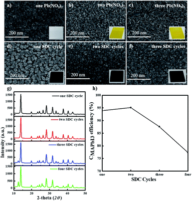
Next, we fabricated stable PHJ perovskite layers on these ZnO/c-TiO2 bilayer ETLs via several SDC and SSIER cycles according to our previously reported approach.26 First, we investigated the surface morphologies of the Pb(NO3)2 layers adsorbed on the surface of the ZnO (0.25 M-Zn) layer and MAPbI3 perovskite films formed by the reaction in the MAI solution. Fig. 4a–f show the SEM images of the surface morphologies of the MAPbI3 perovskite layers fabricated from the optimized SSIER approach with one, two, and three SDC cycles via the ionic layer adsorption of Pb(NO3)2 on the surface of a ZnO (0.25 M-Zn)/c-TiO2 bilayer ETL from an aqueous solution followed by a reaction in the MAI solution. A new layer of Pb(NO3)2 was simultaneously adsorbed on the surface of the ZnO/c-TiO2/FTO substrate, and more platelets and large structures of PbI2 were observed on increasing the number of SDC cycles. The latter may have been produced from the decomposition of the MAPbI3 perovskite structure in the aqueous Pb(NO3)2 solution because of the hydrophobicity of the PbI2 layers formed during MAI removal in an aqueous solution. Subsequently, MAPbI3 films with better stability could be readily prepared in three SSIER cycles, followed by a final incubation of 600 s in the MAI solution after each cycle of Pb(NO3)2 ionic layer adsorption according to a previously reported method.26 As shown in Fig. 4d–f, the MAPbI3 perovskite grows sparsely as cubic-like crystal lumps on the substrate and the MAPbI3 perovskite films exhibit better surface coverage over the substrates after two SDC cycles, resulting in slight increase of the film thickness. This indicates that the MAPbI3 perovskite deposited by repetitive SDC can effectively improve the sparse coverage on ZnO/c-TiO2/FTO. However, the films on this substrate present pin-holes compared to those on the ZnO/mp-TiO2/c-TiO2/FTO substrate. Fig. 4g and h show the XRD patterns of these MAPbI3 perovskite layers and the correlation between the perovskite conversion and the SDC repetition time, respectively. Interestingly, the MAPbI3 perovskite films fabricated with one and two SDC cycles showed superior crystallinities, which were gradually reduced after three SDC cycles. Moreover, based on the XRD patterns, the conversion of MAPbI3 (CMAPbI3) can be qualitatively defined using the peak intensities of PbI2 and MAPbI3 at 2θ = 12.7° and 14.2°, respectively.7,31,32
| CMAPbI3 = I12.7°/(I12.7° + I14.2°) | (1) |
As shown in Fig. 4h, a greater number of SDC cycles (three SDCs) can lead to lower conversion values for MAPbI3 perovskites generated from PbI2. This is because the continuous diffusion of MAI into the film may be hindered by the PHJ MAPbI3 perovskite structures formed on the surface of the film fabricated using more than three SDC cycles on the ZnO/c-TiO2/FTO substrate, thereby decreasing the reaction rate of Pb(NO3)2 (or PbI2) and MAI.
Fig. 5 shows the UV-vis absorption and photoluminescence (PL) spectra for the PHJ MAPbI3 perovskite films deposited on ZnO (0.25 M-Zn)/c-TiO2/FTO under the designated number of SDC cycles. The PL spectra of all the used Zn concentrations (0.19 M-Zn, 0.25 M-Zn, 0.38 M-Zn, and 0.75 M-Zn) under optimized two SDC cycles can be seen in Fig. S5.† The films show typical absorption behaviors, with a shoulder band between 500 and 550 nm and onset points near 790 nm (optical band gap < 1.5 eV). As shown in Fig. 5, after two SDC cycles, the MAPbI3 perovskite films exhibit much better light absorption efficiency at wavelengths below 500 nm than those subjected to one SDC cycle. Moreover, increased PL intensities are observed in the PHJ MAPbI3 perovskite films fabricated with a greater number of SDC cycles. These results may be attributed to the better surface coverage, morphology, and film thickness of the PHJ MAPbI3 perovskite films on the substrate after two SDC cycles and they are consistent with those of the SEM images shown in Fig. 4.
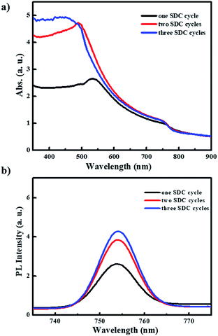 | ||
| Fig. 5 (a) UV-vis absorption and (b) photoluminescence spectra for these PHJ MAPbI3 perovskite films deposited on ZnO (0.25 M- Zn)/c-TiO2/FTO under designed SDC cycles. | ||
3.2 ZnO thickness effects
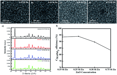
We also investigated the thickness effects of the ZnO layers for the PHJ MAPbI3 perovskite film morphology formed on the ZnO/c-TiO2/FTO substrate by the sequential dip-coating approach. Fig. 6a–d show the SEM images of the surface morphologies of the MAPbI3 perovskite layers fabricated on ZnO (0.19 M-Zn), ZnO (0.25 M-Zn), ZnO (0.38 M-Zn), and ZnO (0.75 M-Zn) over the c-TiO2 layers under two SDC and three SSIER cycles; Fig. 6e shows the XRD patterns of these MAPbI3 perovskite layers and Fig. 6f shows the CMAPbI3 values for various thicknesses of the ZnO layers. The long-term environmental and thermal stability of the PHJ PrSCs devices under optimized two SDC cycles can be confirmed from Fig. S6† and the impedance spectra in Fig. S7,† respectively. As shown in Fig. 6a–d, the MAPbI3 perovskite grows sparsely as cubic-like crystal lumps on the ZnO/c-TiO2/FTO substrate, while the thicker ZnO layers provide better surface coverage of the MAPbI3 perovskite films. As shown in Fig. 6e, the MAPbI3 films fabricated on the thin ZnO (0.19 M-Zn) and ZnO (0.25 M-Zn) layers over the c-TiO2/FTO substrate exhibit excellent perovskite crystallinities; however, the crystallinities gradually decrease in the ZnO layers prepared with higher concentrations of the ZnO precursors (>0.38 M-Zn). The conversion of MAPbI3 (CMAPbI3) based on these XRD patterns could be qualitatively correlated with the decreasing perovskite crystallinities of the MAPbI3 films, as shown in Fig. 6f. Thus, the smoother surfaces of the ZnO layer over the c-TiO2/FTO substrate lead to better surface coverage of the MAPbI3 films. The surface coverage may be affected by the surface roughness and morphologies of the MAPbI3 perovskite layers fabricated on ZnO (0.19 M-Zn), ZnO (0.25 M-Zn), ZnO (0.38 M-Zn), and ZnO (0.75 M-Zn), but it leads to poorer perovskite crystallinities of the MAPbI3 films.3.3 Photovoltaic performances of PHJ PrSCs
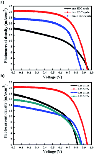
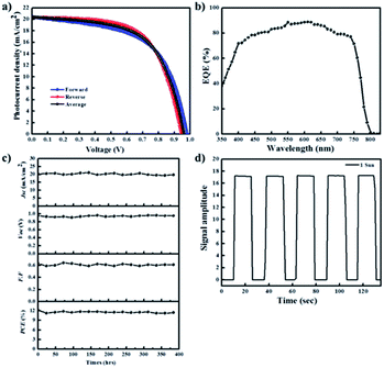
Subsequently, we evaluated the photovoltaic performances of PHJ PrSCs with perovskite films fabricated using the simple dip-coating deposition approach on thin ZnO/c-TiO2 bilayer ETL. The PHJ PrSC devices were fabricated with the n–i–p configuration of FTO/c-TiO2/ZnO/MAPbI3/HTM/MoO3/Ag. The conductivity and efficiency of spiro-OMeTAD used as the HTM improved after doping additives such as 4-tert-butylpyridine (t-BPy) and lithium bis(trifluoromethanesulfonyl)imide (Li-TFSI). We determined the optimum photovoltaic performances by comparing more than 200 individual solar cell devices. These outcomes were due to the superior surface morphology and better crystallinity of the films obtained after two SDC cycles. Fig. 7 shows the current–voltage (J–V) curves under AM 1.5 irradiation (100 mW cm−1) for the PHJ PrSCs based on (a) MAPbI3 perovskite layers fabricated by the designated number of the SDC cycles, followed by three SSIER cycles on ZnO (0.25 M-Zn) over the c-TiO2 layers and (b) the MAPbI3 perovskite layers fabricated on ZnO (0.19 M-Zn), ZnO (0.25 M-Zn), ZnO (0.38 M-Zn), and ZnO (0.75 M-Zn) over the c-TiO2 layers via two SDC cycles. The optimization of the device performances is illustrated in Fig. S2–S4.† As shown in Fig. 7a, better device performances are observed for the PHJ PrSC devices with the MAPbI3 perovskite layers fabricated by two SDC and three SSIER cycles on the ZnO (0.25 M-Zn)/c-TiO2 bilayer ETL; the PCEs are notable with a maximum/average of 12.17/12.03%. Also, the short-circuit current density (Jsc) is 20.33 mA cm−2, open-circuit voltage (Voc) is 0.95 V, and fill factor (FF) is 0.63, and the PCE is comparable to the PCE of 12.41% of the PHJ PrSCs fabricated with a similar configuration using the mp-TiO2 scaffolds according to our previous report.26 One SDC cycle yields the PCEs (maximum/average) of 6.45/6.07% with Jsc = 14.29 mA cm−2, Voc = 0.96 V, and FF = 0.47; three SDC cycles provide PCEs of 9.47/9.17% with Jsc = 17.56 mA cm−2, Voc = 0.87 V, and FF = 0.62. With two SDC and three SSIER cycles, we also determined the most efficient device performances of PHJ PrSCs fabricated with the MAPbI3 perovskite layers deposited on ZnO (0.25 M-Zn) over the c-TiO2 layers compared with those for ZnO (0.19 M-Zn), ZnO (0.38 M-Zn), and ZnO (0.75 M-Zn), as shown in Fig. 7b. The results are summarized in Table S1† and the photovoltaic performances based on the hysteresis behaviors of PHJ PrSCs fabricated under the optimized conditions are tabulated in Table S2.† These results can be explained by the surface coverage and crystallinities of the MAPbI3 perovskite films subjected to different SDC cycles on the ZnO (0.25 M-Zn)/c-TiO2 bilayer ETL, as shown in Fig. 4 and 6.Fig. 8 shows (a) the hysteresis of the J–V curves in both scan directions under AM 1.5 irradiation (100 mW cm−1), (b) EQE spectra, (c) stability, and (d) photoswitching phenomenon for the most efficient PHJ PrSCs fabricated using the dip-coating deposition approach on the thin ZnO/c-TiO2 bilayer ETL. Typical n–i–p PrSCs fabricated with the mp-TiO2 scaffolds often show hysteretic J–V behavior depending on the scan direction (reverse or forward) due to varying charge extraction or transportation rates of the holes and electrons separated from the excitons.10 Meanwhile, most of these PHJ PrSCs exhibited negligible differences in the Jsc and Voc values in both directions except for the FF values, which were slightly reduced in the forward direction. Nonetheless, the average of the PCE values obtained in both the directions was approximately 4% lower than the PCE in the reverse direction, with good EQE in the light-absorption region. Furthermore, these PHJ PrSCs showed good operational stability without significant loss in the photovoltaic performance for 400 h under 1 sun light intensity and a fast and excellent photocurrent repetition response, as shown in Fig. 8c and d, respectively.
4. Conclusions
We successfully fabricated high-performance PHJ PrSCs, where the perovskite film was prepared using a facile, environmentally benign, efficient, and low-cost dip-coating deposition approach on a thin ZnO/c-TiO2 bilayer ETL. Outstanding performances were achieved from the PHJ PrSC devices with the configuration FTO/c-TiO2/ZnO/(CH3NH3)PbI3/spiro-OMeTAD/MoO3/Ag, with notable PCEs compared to those of the PHJ PrSCs fabricated with a similar configuration using the mp-TiO2 scaffolds. We found that these PHJ PrSCs exhibited better performance and stability with thinner ZnO layers in contrast to those on the mp-TiO2 scaffolds, indicating that the thickness of the ZnO layer in the PHJ architecture significantly affected the surface coverage, morphology, crystallinity, and stability of the MAPbI3 perovskite films processed by dip-coating deposition. Thus, we successfully realized a high-performance PHJ PrSC device architecture with an easily processed perovskite film using the sequential dip-coating deposition approach. This work represents significant progress toward environmentally benign and low-cost manufacturing processes for large-area PrSCs.Conflicts of interest
The authors declare no conflict of interest.Acknowledgements
This work was financially supported by Chosun University, 2016.References
- A. Kojima, Y. Teshima, T. Shirai, T. Miyasaka and S. Brabec, Organometal halide perovskites as visible-light sanitizers for photovoltaic cells, J. Am. Chem. Soc., 2009, 131(17), 6050 CrossRef CAS PubMed.
- J. H. Noh, S. H. Im, J. H. Heo, T. N. Mandal and S. I. Seok, Chemical management for colorful, efficient, and stable inorganic-organic hybrid nanostructured solar cells, Nano Lett., 2013, 13(4), 1764 CrossRef CAS PubMed.
- G. Xing, N. Mathews, S. Sun, S. S. Lim, Y. M. Lam, M. Gratzel, S. Mhaisalkar and T. C. Sum, Long-range balanced electron- and hole-transport lengths in organic-inorganic CH3NH3PbI3, Adv. Mater., 2013, 342(6156), 344 CAS.
- T. Baikie, Y. Fang, J. M. Kadro, M. Schreyer, F. Wei, S. G. Mhaisalkar, M. Graetzel and T. J. White, Synthesis and crystal chemistry of the hybrid perovskite (CH3NH3) PbI3 for solid-state sensitized solar cell applications, J. Mater. Chem., 2013, 1(18), 5628 RSC.
- P. Gao, M. Gratzel and M. K. Nazeeruddin, Organohalide lead perovskites for photovoltaic applications, Energy Environ. Sci., 2014, 7(8), 2448 RSC.
- H. S. Kim, S. H. Im and N.-G. Park, Organolead halide perovskite: New horizons in solar cell research, J. Phys. Chem. C, 2014, 118(11), 5615 CrossRef CAS.
- N. J. Jeon, J. H. Noh, Y. C. Kim, W. S. Yang, S. Ryu and S. I. Seok, Solvent engineering for high-performance inorganic-organic hybrid perovskite solar cells, Nat. Mater., 2014, 13(9), 897 CrossRef CAS PubMed.
- H.-S. Kim, C.-R. Lee, J.-H. Im, K.-B. Lee, T. Moehl, A. Marchioro, S.-J. Moon, R. Humphry-Baker, J.-H. Yum, J. E. Moser, M. Gratzel and N.-G. Park, Lead iodide perovskite sensitized all-solid-state submicron thin film mesoscopic solar cell with efficiency exceeding 9%, Sci. Rep., 2012, 2(1), 591 CrossRef PubMed.
- M. Liu, M. B. Johnston and H. J. Snaith, Efficient planar heterojunction perovskite solar cells by vapor deposition, Nature, 2013, 501(7467), 395 CrossRef CAS PubMed.
- H. Zhou, Q. Chen, G. Li, S. Luo, T.-b. Song, H.-S. Duan, Z. Hong, J. You, Y. Liu and Y. Yang, Interface engineering of highly efficient perovskite solar cells, Science, 2014, 345(6196), 542 CrossRef CAS PubMed.
- W. S. Yang, B. W. Park, E. H. Jung, N. J. Jeon, Y. C. Kim, D. U. Lee, S. S. Shin, J. Seo, E. K. Kim, J. H. Noh and S. Seok, Iodide management in formamidinium-lead-halide-based perovskite layers for efficient solar cells, Science, 2017, 356(6345), 1376 CrossRef CAS PubMed.
- A. Mei, X. Li, L. Liu, Z. Ku, T. Liu, Y. Rong, M. Xu, M. Hu, J. Chen, Y. Yang, M. Gratzel and H. Han, A hole-conductor-free fully printable mesoscopic perovskite solar cell with high stability, Science, 2014, 345(6194), 295 CrossRef CAS PubMed.
- J. Shi, J. Dong, S. Lv, Y. Xu, L. Zhu, J. Xiao, X. Xu, H. Wu, D. Li, Y. Luo and Q. Meng, Parameters influencing the deposition of methylammonium lead halide iodide in hole conductor free perovskite-based solar cells, Appl. Phys. Lett., 2014, 104(2), 063901 CrossRef.
- W. Bergmann, S. A. L. Weber, F. Javier Ramos, M. K. Nazeeruddin, M. Gratzel, D. Li, A. L Domanski, I. Lieberwirth, S. Ahmad and R. Berger, Real-space observation of unbalanced charge distribution inside a perovskite-sensitized solar cell, Nat. Commun., 2014, 5(1), 5001 CrossRef PubMed.
- T. Leijtens, G. E. Eperon, S. Pathak, A. Abate, M. M. Lee and H. J. Snaith, Overcoming ultraviolet light instability of sensitized TiO2 with meso-superstructured organometal tri-halide perovskite solar cells, Nat. Commun., 2013, 4(1), 2885 CrossRef PubMed.
- E. Mosconi, E. Ronca and F. De Angelis, First-principles investigation of the TiO2/organohalide perovskites interface: The role of interfacial chlorine, J. Phys. Chem. Lett., 2014, 5(15), 2619 CrossRef CAS PubMed.
- P. Schulz, E. Edri, S. Kirmayer, G. Hodes, D. Cahen and A. Kahn, Interface energetics in organo-metal halide perovskite-based photovoltaic cells, Energy Environ. Sci., 2014, 7(4), 1377 RSC.
- E. J. Juarez-Perez, M. Wuβler, F. Fabregat-Santiago, K. Lakus-Wollny, E. Mankel, T. Mayer, W. Jaegermann and I. Mora-Sero, Role of the selective contacts in the performance of lead halide perovskite solar cells, J. Phys. Chem. Lett., 2014, 5(4), 680 CrossRef CAS PubMed.
- L. Kavan, N. Tetreault, T. Moehl and M. Gratzel, Electrochemical characterization of TiO2 blocking layers for dye-sensitized solar cells, J. Phys. Chem. C, 2014, 118(30), 16408 CrossRef CAS.
- X. Xu, H. Zhang, J. Shi, J. Dong, Y. Luo and L. D. Meng, Highly efficient planar perovskite solar cells with a TiO2/ZnO electron transport bilayer, J. Mater. Chem. A, 2015, 3(38), 19288 RSC.
- D. Son, J. K. Im, H. Kim and N. G. Park, 11% efficient perovskite solar cell based on ZnO nanorods: An effective charge collection system, J. Phys. Chem. C, 2014, 30(118), 16567 CrossRef.
- W. Zhang, M. Saliba, D. T. Moore, K. Sandeep, M. T. Horantner, T. Stergiopoulos, S. D. Stranks, G. E. Eperon, A. Webber, A. Abate, A. Sadhanala, S. Yao, Y. Chen, R. H. Friend, L. A. Lara Estroff, U. Wiesner and H. J. Snaith, Ultrasmooth organic–inorganic perovskite thin-film formation and crystallization for efficient planar heterojunction solar cells, Nat. Commun., 2015, 6(1), 6142 CrossRef CAS PubMed.
- F. K. Aldibaja, L. Badia, E. M. Marza, R. S. Sanchez, E. M. Barea and I. M. Sero, Effect of different lead precursors on perovskite solar cell performance and stability, J. Mater. Chem. A, 2015, 3(17), 9194 RSC.
- H. Li, S. Jiao, J. Ren, H. Li, S. Gao, J. Wang, D. Wang, Q. Yu, Y. Zhang and L. Li, Reaction mechanism of a PbS-on-ZnO heterostructure and enhanced photovoltaic diode performance with an interfacemodulated heterojunction energy band structure, Phys. Chem. Chem. Phys., 2016, 18(5), 4144 RSC.
- H. Li, S. Jiao, H. Li and X. Zhang, Tunable growth of PbS quantum dot–ZnO heterostructure and mechanism analysis, CrystEngComm, 2015, 17(25), 4722 RSC.
- M. Adnan and J. K. Lee, All Sequential Dip-Coating Processed Perovskite Layers from an Aqueous Lead Precursor for High Efficiency Perovskite Solar, Sci. Rep., 2018, 8(1), 2168 CrossRef PubMed.
- M. Saliba, T. Matsui, J. Y. Seo, K. Domanski, J. P. C. Baena, M. K. Nazeeruddin, S. M. Zakeeruddin, W. Tress, A. Abate, A. Hagfeldt and M. Gratzel, Cesium-containing triple cation perovskite solar cells: improved stability, reproducibility and high efficiency, Energy Environ. Sci., 2016, 9(6), 1989 RSC.
- Y. Sun, J. H. Seo, C. J. Takacs, J. Seifter and A. J. Heeger, Inverted polymer solar cells integrated with a low-temperature-annealed sol-gel-derived ZnO Film as an electron transport layer, Adv. Mater., 2011, 23(14), 1679 CrossRef CAS PubMed.
- N. Ahn, D. Y. Son, I. H. Jang, S. M. Kang, M. Choi and N. G. Park, Highly reproducible perovskite solar cells with average efficiency of 18.3% and best efficiency of 19.7% fabricated via Lewis base adduct of Lead iodide, J. Am. Chem. Soc., 2015, 137(27), 8696 CrossRef CAS PubMed.
- H. J. Snaith, A. Abate, J. A. Ball, E. Eperon, T. Leijtens, N. K. Noel, S. D. Stranks, J. T. w. Wang, K. Wojciechowski and W. Zhang, Anomalous Hysteresis in Perovskite Solar Cells, J. Phys. Chem. Lett., 2014, 5(9), 1511 CrossRef CAS PubMed.
- E. L. Unger, E. T. Hoke, C. D. Bailie, W. H. Nguyen, A. R. Bowring, T. Heumuller, M. G. Christoforo and M. D. McGeHee, Hysteresis and transient behavior in current-voltage measurements of hybrid-perovskite absorber solar cells, Energy Environ. Sci., 2014, 7(11), 3690 RSC.
- O. Malinkiewca, A. Yella, Y. Lee, G. Espallargas, M. Graetzel, M. K. Nazeeruddin and H. J. Bolink, Perovskite solar cells employing organic charge-transport layers, Nat. Photonics, 2014, 8(2), 128 CrossRef.
- X. Xu, H. Zhang, J. Dong, Y. Lou, D. Li and Q. Meng, Highly efficient planar perovskite solar cells with a TiO2/ZnO electron transport layer, J. Mater. Chem. A, 2015, 3(38), 19293 RSC.
- C. Zhang, G. Zhai, Y. Zhang, W. Gao, Z. Shao, L. Zheng, F. Mei, H. Zhang, Y. Yang, X. Li, X. Liu and B. Xu, Enhanced device performance and stability of perovskite solar cells with low temperature ZnO/TiO2bilayered electron transport layers, RSC Adv., 2018, 8(41), 23026 Search PubMed.
Footnote |
| † Electronic supplementary information (ESI) available. See DOI: 10.1039/c9ra09607h |
| This journal is © The Royal Society of Chemistry 2020 |

