Graphene-based Fe-coordinated framework porphyrin as an interlayer for lithium–sulfur batteries†
Jin-Lei
Qin
a,
Bo-Quan
Li
 b,
Jia-Qi
Huang
 *c,
Long
Kong
 b,
Xiang
Chen
 b,
Hong-Jie
Peng
 b,
Jin
Xie
 b,
Ruiping
Liu
*a and
Qiang
Zhang
 *b
*b
aDepartment of Materials Science and Engineering, China University of Mining and Technology (Beijing), Beijing 100083, China. E-mail: lrp@cumtb.edu.cn
bBeijing Key Laboratory of Green Chemical Reaction Engineering and Technology, Department of Chemical Engineering, Tsinghua University, Beijing 100084, China. E-mail: zhang-qiang@mails.tsinghua.edu.cn
cAdvanced Research Institute of Multidisciplinary Science, Beijing Institute of Technology, Beijing 100081, China. E-mail: jqhuang@bit.edu.cn
First published on 31st January 2019
Abstract
Lithium–sulfur (Li–S) batteries are deemed to be one of the most promising energy storage systems because of their high energy density, low cost, and environmental benignancy. However, existing drawbacks including the shuttling of intermediate lithium polysulfides (LiPSs), the insulating nature of sulfur and lithium sulfides, and the considerable volume change of the sulfur cathode result in low sulfur utilization and rapid capacity fading. Herein, graphene-based iron-coordinated framework porphyrin (G@POF-Fe) is proposed to fabricate multi-functional separators to retard these obstacles. Benefiting from the superior electrical conductivity of graphene and favorable chemisorption of iron-coordinated porphyrin, the as-obtained G@POF-Fe interlayer can simultaneously facilitate the charge transport, suppress the LiPS shuttling, and buffer the volume expansion. With these advantages, Li–S batteries with the G@POF-Fe interlayers deliver an outstanding rate capability (957 and 830 mA h g−1 at 1 and 2C, respectively), impressive cycling stability (a high initial capacity of 1065 mA h g−1, retaining 671 mA h g−1 after 500 cycles at 0.5C), and excellent high-sulfur-loading performance (5.2 mA h cm−2 with a sulfur loading of 6.54 mg cm−2 for 250 cycles) even at high current densities. The framework porphyrin serves as a versatile material to precisely regulate electrical conductivity and polysulfide affinity at a molecular lever, which enriches the interface design strategies for high-performance Li–S batteries.
1. Introduction
The increasing demand of high-energy-density and long-life energy storage devices motivates considerable efforts to explore new battery systems.1–4 Among them, rechargeable lithium–sulfur (Li–S) batteries have attracted vast interests because of their ultrahigh energy density (2600 W h kg−1), abundance of sulfur, and environmental compatibility.5–7 Despite significant achievements in designing leading-edge Li–S batteries, their practical utilizations are impeded by a multitude of obstacles,8 including, (1) the insulating nature of sulfur/lithium sulfide (S/Li2S) that reduces the overall conductivity of the electrode and hence affects the utilization of sulfur, (2) the notorious shuttle effect induced by the dissolution and diffusion of soluble lithium polysulfides (LiPSs) that induces rapid capacity fading and poor Coulombic efficiency, and (3) the considerable volume expansion of the sulfur cathode during cycling which leads to dramatic phase migration and detachment of sulfur from the conductive skeleton to form dead sulfur species.9–11To tackle these issues, great efforts have been devoted to building multifunctional interlayers toward advanced Li–S batteries.10,12–15 A ubiquitously employed strategy is to use graphene based composites as the interlayer coated on the cathode side of separators16–19 to prevent the diffusion of LiPSs such as reduced graphene oxide and its hybrid interlayers,20–22 binary solvent-engineered polysulfide-blocking shields, porous graphene modified separators,23,24 and other composite separators with multifunctional interlayers.25–27 However, nonpolar nanocarbon materials commonly exhibit poor affinity to LiPSs and undesirable wetting properties for smooth electrolyte infiltration and rapid lithium-ion transfer.28 Heteroatom dopants in carbon scaffolds have been experimentally and theoretically demonstrated to anchor LiPSs within the cathode side through sulphifilic interactions or the formation of lithium bonds.11,28–32
Covalent organic framework materials represent an emerging family of materials that can be precisely controlled at the atomic level.33 Pre-designed organic ligands coordinate with various transition metal ions to afford the possibility to accurately synthesize functional materials with targeted properties.34 Herein, iron-coordinated framework porphyrin hybridized with a graphene substrate (denoted as G@POF-Fe) was proposed to serve as a multifunctional interlayer in Li–S batteries. The lithiophilic nitrogen content and sulphifilic iron center act as bifunctional active sites to retard LiPS diffusion, while the porous scaffold provides large space to accommodate volume variation of the sulfur species. The designed interlayers endow the sulfur cathode with attractive battery performances in terms of cyclability and rate capability even under high areal sulfur loading conditions.
2. Results and discussion
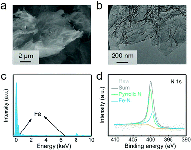
The G@POF-Fe was one-pot synthesized by growing Fe-coordinated framework porphyrin (POF) on the surface of G templates. The G@POF-Fe exhibits a fluffy morphology characterized by scanning electron microscopy (SEM) (Fig. 1a). The tortuous graphene layer favors the exposure of the adsorption sites and reutilizes a large amount of sulfur species. Further transmission electron microscopy (TEM) was conducted to view the fold structure of graphene and thin POF layers (Fig. 1b). The POF “skin” on the graphene “body” is too thin to be clearly distinguished, which indicates that there is no noticeable POF aggregation. The synthetic G@POF-Fe was evaluated by Fourier transform infrared spectrometry (FTIR) (Fig. S1a, ESI†), where the blueshift of the adsorption band from 1100 cm−2 of G to 1240 cm−1 of G@POF-Fe is assigned as the additional C–N vibration of POF to indicate successful fabrication of G@POF-Fe. The X-ray photoelectron spectroscopy (XPS) survey spectra of G@POF-Fe exhibits a distinct N content and an inconspicuous Fe 2p signal (Fig. S1b, ESI†), further confirming the existence of POF-Fe and successful hybridization with G. Fig. 1c displays the energy dispersive spectrometer (EDS) analysis for G@POF-Fe, also confirming the contribution of Fe in a G@POF-Fe sample. Fig. 1d exhibits the fine-fitted N 1s XPS spectrum of G@POF-Fe with the deconvolution peaks, where one prominent signal centering at 399.3 eV can be assigned to Fe–N bonding, proving that iron ions are coordinated with porphyrin rings.35 The other peak can be clearly assigned to pyrrolic N (400.1 eV).36,37 In particular, the pyrrolic N was suggested to possess a strong affinity to LiPS species.38–40 | ||
| Fig. 1 Characterization of the G@POF-Fe power. (a) SEM image, (b) TEM image, (c) EDS analysis, and (d) high-resolution N 1s XPS spectra of G@POF-Fe. | ||
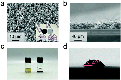
G@POF-Fe powders were then filtrated on polypropylene (PP) substrates to obtain a composite functional separator. The spherical like G@POF-Fe powders are uniformly deposited on the PP substrate to form a conductive and chemisorptive interlayer (Fig. 2a). The digital image (inset in Fig. 2a) exhibits the Janus surface of the G@POF-Fe modified separator with a diameter of 17.0 mm. Fig. 2b illustrates a cross-sectional image of the modified separator, where a 35 μm thickness coating layer was closely filtrated on the PP substrate.
The adsorptive behaviors between LiPSs and G@POF-Fe were tested in a Li2S6 solution. About 2.0 mg G@POF-Fe dry powders were added into 1.0 mL of Li2S6/DME solution (5.0 mmol L−1 [S]). The yellow-brown solution was decolorized compared with the Li2S6/DME solution after 3.0 hours as shown in Fig. 2c. To further demonstrate the strong adsorption of G@POF-Fe for LiPS, the surface chemistry of the G@POF-Fe promoter before and after adsorption of Li2S6 (named as G@POF-Fe-Li2S6) was evaluated by XPS. In pristine G@POF-Fe, the obvious Fe3+ peaks appear at 711.2 and 724.5 eV, respectively. Upon interaction with Li2S6, two Fe3+ peaks emerge at 710.6 and 723.0 eV offsetting 0.6 and 1.5 eV, respectively, which manifests the strong chemical interaction between G@POF-Fe and Li2S6.41 The G@POF-Fe possesses a high electrical conductivity (81 S cm−1) and a good wettability between the electrolyte and interlayer (Fig. 2d), which are beneficial for the rapid redox reaction of sulfur species in a working battery.
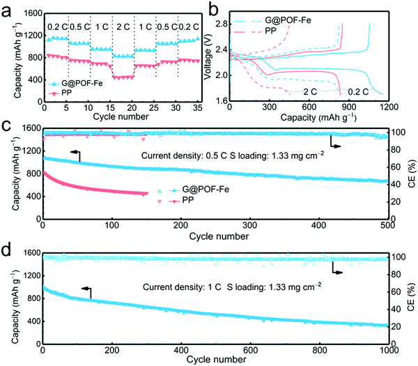
The G@POF-Fe decorated separator was further evaluated in Li–S cells. When cycled at 0.2, 0.5, 1, and 2C (1C = 1672 mA g−1), the G@POF-Fe cell delivered impressive discharge capacities of 1120, 1060, 957, and 830 mA h g−1, respectively (Fig. 2a). As the current density returned to 1 and 0.5C, the corresponding discharge capacities of G@POF-Fe cells restored to 936 and 1061 mA h g−1, respectively. In contrast, the rate performance of cells with bare PP separator are inferior due to the loss of active sulfur resulting from serious polysulfide shuttling.
The corresponding galvanostatic discharge/charge curves of rate capacities at 0.2 and 2C are plotted in Fig. 3b. The flat and smooth discharge curve especially at 2C of the second plateau indicates the favored reaction kinetics of the Li–S batteries with G@POF-Fe separators. The short second discharge plateau and expanded polarization voltage of routine cells were attributed to the lack of LiPS chemisorption and sluggish redox kinetics.42–44
The long-term cycling performance at 0.5C was evaluated to validate the stability of Li–S batteries. As expected, the Li–S cell with the G@POF-Fe separator exhibited a capacity of 671 mA h g−1 after 500 cycles (Fig. 3c), which is in sharp contrast with routine cell (only maintained 461 mA h g−1 after 150 cycles). The LiPS shuttling, which likely takes place in the upper plateau of the discharge profile, is a primary factor for rapid capacity fading in Li–S cells. The capacity retention of the upper plateau is 84% upon 100 cycles (Fig. S3b, ESI†) much higher than that of the PP cell, indicating excellent LiPS anchoring through chemisorption of the G@POF-Fe interlayer.
Cyclic voltammetry (CV) profiles of the G@POF-Fe Li–S battery with a scan rate of 0.1 mV s−1 in a potential window from 1.7 to 2.8 V also showed the advances of the Li–S cells with the G@POF-Fe interlayers. As shown in Fig. S4 (ESI†), the well overlapping profiles from the first to third cycle demonstrated an excellent cyclability. The cathodic peak I (2.30 V) and peak II (2.02 V) corresponded to the successive reduction of sulfur to soluble LiPSs and further to Li2S. The anodic peak III (2.32 V) with a shoulder peak IV (2.4 V) were ascribed to the reverse reaction.42 More importantly, owing to the suppressed shuttle effect and improved redox kinetics, the cell with the G@POF-Fe separator delivered an ultralow capacity decay rate of 0.067% per cycle at 1C for 1000 cycles (Fig. 3d and Fig. S5, ESI†).
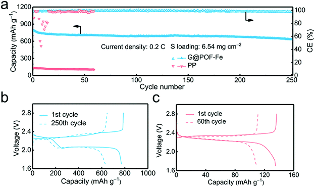
In order to verify the feasibility of this novel separator for the practical application of Li–S batteries, a high areal loading of sulfur is indispensable.45,46 The G@POF-Fe cell exhibited a high initial capacity of 789 and reserved 633 mA h g−1 with a sulfur loading of 6.54 mg cm−2 at 0.2C after 250 cycles (Fig. 4a). In contrast, the PP separator cell delivered a poor capacity of 136 mA h g−1. The significantly improved capacity is attributed to the enhanced kinetics in liquid–solid conversion. The charge–discharge profiles of the G@POF-Fe cell possess two typical plateaus, which sharply contrasted to the routine cell with the disappearance of the second plateau caused by the limited conductive skeleton which can hardly promote the electrochemical reactions.43,47 The vanished second discharge plateau confirmed that the soluble Li2S6/Li2S4 can hardly be converted into solid Li2S2/Li2S in the cells with PP separators.28,48
To demonstrate the versatility of the framework porphyrin in coordination with various transition metals, cobalt and nickel ions were also coordinated with POF (donated as G@POF-Co and G@POF-Ni) and investigated in Li–S batteries. TEM images revealed that a thin POF layer with Ni and Co uniformly spread on the graphene without any aggregation, which was beneficial for the exposure of active sites to bind LiPS and propel the conversion of sulfur species (Fig. S6, ESI†). The G@POF-Ni cell delivered a higher initial capacity, yet, with a faster capacity fading compared with the G@POF-Co cell (Fig. S7, ESI†) due to inferior chemisorption to LiPSs (Fig. S8, ESI†).
Framework porphyrin materials represent an emerging class of two-dimensional (2D) materials that allow the topological structure to be precisely controlled by engineering of the organic units and transition metal centers,49 which provides an opportunity to tune the affinity to LiPSs in a working Li–S cell. The electronegative nitrogen content of porphyrin ligands and electropositive transition metal centers concurrently serve as lithiophilic and sulphifilic sites to regulate LiPS transportation. Beyond other carbon hosts,3,48,50 the current 2D graphene substrate with expediting electrical conductivity imparted the POF derived active sites with superior electrical conductivity to facilitate sulfur species kinetics. The chemical advantage and structure uniqueness endowed G@POF-Fe with an ideal bifunctional interlayer to boost the electrochemical performance of Li–S batteries.
3. Conclusions
G@POF-Fe was proposed as a functional interlayer to boost the electrochemical performance of Li–S batteries. The iron-coordinated framework porphyrin was in situ hybridized with the graphene substrate, forming an electron conductive and LiPS adsorptive interface to kinetically facilitate sulfur species reactions and chemically retard LiPS diffusion. The lithiophilic sites of nitrogen species and sulphifilic sites of iron centers derived from the 2D framework porphyrin bifunctionally bind with LiPSs, while the graphene substrates afford electron pathways to impart sufficient electrical conductivity to sulfur species in the entire sulfur interconversions. Therefore, G@POF-Fe filtrated on the PP separator significantly enhanced the cyclability and rate capability. Li–S batteries applying G@POF-Fe exhibited a high initial capacity of 1120 mA h g−1 at 0.2C and maintained a high capacity of 830 mA h g−1 at 2C. At a practically high sulfur loading of 6.54 mg cm−2, the cell with a G@POF-Fe separator delivered a high capacity of 789 mA h g−1 at a current density of 0.2C and a capacity retention of 80.3% upon 250 cycles. The framework porphyrin also demonstrated feasibility to coordinate other transition metal ions such as cobalt and nickel, wherein the sterical structure and ligand speciation of the organic framework needed to be further regulated to satisfy the requirements of conductivity and affinity of the sulfur scaffolds in a working battery.Conflicts of interest
There are no conflicts to declare.Acknowledgements
This work was supported by the National Key Research and Development Program (2016YFA0202500 and 2016YFA0200101), the National Natural Science Foundation of China (21776019, 21825501, 21808124, and 21805162), Beijing Key Research and Development Plan (Z181100004518001), and China Postdoctoral Science Foundation (2018M630165).References
- X. Shen, H. Liu, X. B. Cheng, C. Yan and J. Q. Huang, Energy Storage Mater., 2018, 12, 161–175 CrossRef.
- L. Y. Li, C. G. Chen and A. S. Yu, Sci. China: Chem., 2017, 60, 1402–1412 CrossRef CAS.
- H. Q. Wang, W. C. Zhang, J. Z. Xu and Z. P. Guo, Adv. Funct. Mater., 2018, 28, 1707520 CrossRef.
- X.-Q. Zhang, C.-Z. Zhao, J.-Q. Huang and Q. Zhang, Engineering, 2018, 4, 831–847 CrossRef.
- R. Fang, S. Zhao, Z. Sun, W. Wang, H.-M. Cheng and F. Li, Adv. Mater., 2017, 29, 1606823 CrossRef PubMed.
- S. H. Chung, C. H. Chang and A. Manthiram, Adv. Funct. Mater., 2018, 28, 1801188 CrossRef.
- W. Fan, L. S. Zhang and T. X. Liu, Mater. Chem. Front., 2018, 2, 235–252 RSC.
- H.-J. Peng, J.-Q. Huang and Q. Zhang, Chem. Soc. Rev., 2017, 46, 5237–5288 RSC.
- X. Liu, J. Q. Huang, Q. Zhang and L. Mai, Adv. Mater., 2017, 29, 1601759 CrossRef PubMed.
- J. Q. Huang, Q. Zhang and F. Wei, Energy Storage Mater., 2015, 1, 127–145 CrossRef.
- J. Gou, H. Z. Zhang, X. F. Yang, Y. Q. Chen, Y. Yu, X. F. Li and H. M. Zhang, Adv. Funct. Mater., 2018, 28, 1707272 CrossRef.
- H. Zhang, Z. B. Zhao, Y. Liu, J. J. Liang, Y. N. Hou, Z. C. Zhang, X. Z. Wang and J. S. Qiu, J. Energy Chem., 2017, 26, 1282–1290 CrossRef.
- M. Liu, X. Y. Qin, Y. B. He, B. H. Li and F. Y. Kang, J. Mater. Chem. A, 2017, 5, 5222–5234 RSC.
- Y. C. Jeong, J. H. Kim, S. Nam, C. R. Park and S. J. Yang, Adv. Funct. Mater., 2018, 28, 1707411 CrossRef.
- T. Y. Wang, K. Kretschmer, S. H. Choi, H. Pang, H. G. Xue and G. X. Wang, Small Methods, 2017, 1, 1700089 CrossRef.
- W. D. Zhang, Z. Y. Tu, J. W. Qian, S. Choudhury, L. A. Archer and Y. Y. Lu, Small, 2018, 14, 1703001 CrossRef PubMed.
- Y. D. Pan, S. L. Chou, H. K. Liu and S. X. Dou, Natl. Sci. Rev., 2017, 4, 917–933 CrossRef.
- N. P. Deng, W. M. Kang, Y. B. Liu, J. G. Ju, D. Y. Wu, L. Li, B. S. Hassan and B. W. Cheng, J. Power Sources, 2016, 331, 132–155 CrossRef CAS.
- Y. Y. Xiang, J. S. Li, J. H. Lei, D. Liu, Z. Z. Xie, D. Y. Qu, K. Li, T. F. Deng and H. L. Tang, ChemSusChem, 2016, 9, 3023–3039 CrossRef CAS PubMed.
- Y. D. Pan, J. R. Hao, X. B. Zhu, Y. H. Zhou and S. L. Chou, Inorg. Chem. Front., 2018, 5, 1869–1875 RSC.
- M. Raja, S. Suriyakumar, N. Angulakshmi and A. M. Stephan, Inorg. Chem. Front., 2017, 4, 1013–1021 RSC.
- H. P. Li, L. C. Sun, Y. G. Zhang, T. Z. Tan, G. K. Wang and Z. Bakenov, J. Energy Chem., 2017, 26, 1276–1281 CrossRef.
- H. J. Peng, D. W. Wang, J. Q. Huang, X. B. Cheng, Z. Yuan, F. Wei and Q. Zhang, Adv. Sci., 2016, 3, 1500268 CrossRef PubMed.
- P. Y. Zhai, H. J. Peng, X. B. Cheng, L. Zhu, J. Q. Huang, W. C. Zhu and Q. Zhang, Energy Storage Mater., 2017, 7, 56–63 CrossRef.
- Y. S. Ye, L. L. Wang, L. L. Guan, F. Wu, J. Qian, T. Zhao, X. X. Zhang, Y. Xing, J. Q. Shi, L. Li and R. J. Chen, Energy Storage Mater., 2017, 9, 126–133 CrossRef.
- Y. H. Cui, X. J. Wu, J. W. Wu, J. Zeng, A. P. Baker, F. Lu, X. Liang, J. Ouyang, J. Y. Huang, X. B. Liu, Z. F. Li and X. H. Zhang, Energy Storage Mater., 2017, 9, 1–10 CrossRef.
- Y. Q. Lai, P. Wang, F. R. Qin, M. Xu, J. Li, K. Zhang and Z. Zhang, Energy Storage Mater., 2017, 9, 179–187 CrossRef.
- Z. Yuan, H. J. Peng, T. Z. Hou, J. Q. Huang, C. M. Chen, D. W. Wang, X. B. Cheng, F. Wei and Q. Zhang, Nano Lett., 2016, 16, 519–527 CrossRef CAS PubMed.
- T. Z. Hou, W. T. Xu, X. Chen, H. J. Peng, J. Q. Huang and Q. Zhang, Angew. Chem., Int. Ed., 2017, 56, 8178–8182 CrossRef CAS PubMed.
- D. R. Deng, F. Xue, Y. J. Jia, J. C. Ye, C. D. Bai, M. S. Zheng and Q. F. Dong, ACS Nano, 2017, 11, 6031–6039 CrossRef CAS PubMed.
- S.-Y. Li, W.-P. Wang, H. Duan and Y.-G. Guo, J. Energy Chem., 2018, 27, 1555–1565 CrossRef.
- Z.-W. Zhang, H.-J. Peng, M. Zhao and J.-Q. Huang, Adv. Funct. Mater., 2018, 28, 1707536 CrossRef.
- X. Feng, X. Ding and D. Jiang, Chem. Soc. Rev., 2012, 41, 6010–6022 RSC.
- L. Kong, B. Q. Li, H. J. Peng, R. Zhang, J. Xie, J. Q. Huang and Q. Zhang, Adv. Energy Mater., 2018, 8, 1800849 CrossRef.
- R. J. Ewen and C. L. Honeybourne, J. Phys.: Condens. Matter, 1991, 3, S303–S310 CrossRef CAS.
- C. Tang, Q. Zhang, M. Q. Zhao, J. Q. Huang, X. B. Cheng, G. L. Tian, H. J. Peng and F. Wei, Adv. Mater., 2014, 26, 6100–6105 CrossRef CAS PubMed.
- H. B. Wang, T. Maiyalagan and X. Wang, ACS Catal., 2012, 2, 781–794 CrossRef CAS.
- L. C. Yin, J. Liang, G. M. Zhou, F. Li, R. Saito and H. M. Cheng, Nano Energy, 2016, 25, 203–210 CrossRef CAS.
- T. Z. Hou, X. Chen, H. J. Peng, J. Q. Huang, B. Q. Li, Q. Zhang and B. Li, Small, 2016, 12, 3283–3291 CrossRef CAS PubMed.
- S. H. Liu, J. Li, X. Yan, Q. F. Su, Y. H. Lu, J. S. Qiu, Z. Y. Wang, X. D. Lin, J. L. Huang, R. L. Liu, B. N. Zheng, L. Y. Chen, R. W. Fu and D. C. Wu, Adv. Mater., 2018, 30, 1706895 CrossRef PubMed.
- G. Zhang, Z. W. Zhang, H. J. Peng, J. Q. Huang and Q. Zhang, Small Methods, 2017, 1, 1700134 CrossRef.
- L. Kong, X. Chen, B. Q. Li, H. J. Peng, J. Q. Huang, J. Xie and Q. Zhang, Adv. Mater., 2018, 30, 1705219 CrossRef PubMed.
- J.-L. Qin, H.-J. Peng, J.-Q. Huang, X.-Q. Zhang, L. Kong, J. Xie, M. Zhao, R. Liu, H. Zhao and Q. Zhang, Small Methods, 2018, 2, 1800100 CrossRef.
- R. Wu, S. Chen, J. Deng, X. Huang, Y. Song, R. Gan, X. Wan and Z. Wei, J. Energy Chem., 2018, 27, 1661–1667 CrossRef.
- S. H. Chung and A. Manthiram, Adv. Mater., 2018, 30, 1705951 CrossRef PubMed.
- W. Guo and Y. Fu, Energy Environ. Mater., 2018, 1, 20–27 CrossRef.
- H. J. Peng, J. Q. Huang, X. B. Cheng and Q. Zhang, Adv. Energy Mater., 2017, 7, 54 Search PubMed.
- Z. Li, N. Zhang, Y. B. Sun, H. Z. Ke and H. S. Cheng, J. Energy Chem., 2017, 26, 1267–1275 CrossRef.
- B. Q. Li, S. Y. Zhang, L. Kong, H. J. Peng and Q. Zhang, Adv. Mater., 2018, 30, 1707483 CrossRef PubMed.
- J. Liang, Z. H. Sun, F. Li and H. M. Cheng, Energy Storage Mater., 2016, 2, 76–106 CrossRef.
Footnote |
| † Electronic supplementary information (ESI) available. See DOI: 10.1039/c8qm00645h |
| This journal is © the Partner Organisations 2019 |


