 Open Access Article
Creative Commons Attribution 3.0 Unported Licence
Three-dimensional catalyst systems from expanded graphite and metal nanoparticles for electrocatalytic oxidation of liquid fuels
Xinyue
Chen†
a,
Hui
Li†
a,
Ting
Zeng
*a,
Yuanyuan
Zhang
a,
Qijin
Wan
*a,
Yawei
Li
b and
Nianjun
Yang
 *ac
*ac
aSchool of Chemistry and Environmental Engineering, Wuhan Institute of Technology, Wuhan 430073, China. E-mail: tingzeng1201@outlook.com; qijinwan@wit.edu.cn
bThe State Key Laboratory of Refractories and Metallurgy, Wuhan University of Science and Technology, Wuhan 430081, China
cInstitute of Materials Engineering, University of Siegen, 57076 Siegen, Germany. E-mail: nianjun.yang@uni-siegen.de
First published on 28th March 2019
Abstract
Cheap and high-performance electrocatalysts are required for fuel cells. Herein, we present the application of three-dimensional (3D) catalyst systems for electrocatalytic oxidation of formic acid and methanol. These systems consist of cost-effective boron-doped expanded graphite (B-EG) as the support and palladium nanoparticles (NPs) or platinum/palladium bimetal NPs as the catalysts. The characterization of these 3D catalyst systems using scanning electron microscopy, transmission electron microscopy, energy-dispersive X-ray, and electrochemical techniques reveals that stable and efficient electrocatalytic methanol oxidation, achieved in a 3D catalyst system of B-EG and PdPt bimetal NPs (with a mass ratio of 1![[thin space (1/6-em)]](https://www.rsc.org/images/entities/char_2009.gif) :
:![[thin space (1/6-em)]](https://www.rsc.org/images/entities/char_2009.gif) 1), is due to its big surface area, high conductivity, and an enhanced amount of exposed active sites from bimetal NPs. This price-reduced, stable, and efficient 3D catalyst system is thus promising to be employed for a large scale production of industrial direct methanol fuel cells.
1), is due to its big surface area, high conductivity, and an enhanced amount of exposed active sites from bimetal NPs. This price-reduced, stable, and efficient 3D catalyst system is thus promising to be employed for a large scale production of industrial direct methanol fuel cells.
Introduction
Development of fuel cells has led to many breakthroughs in the fields of civil and military applications (e.g., transportation, aviation/aerospace, underwater submersible, portable power supply, electric vehicles, wireless communication, and decentralized power stations).1,2 Taking a direct methanol fuel cell (DMFC) as an example, this device converts directly chemical energy into electrical one.3–5 Valued by governments and entrepreneurs all over the world, such a clean energy conversion system has been recognized as a promising device to solve the problem of energy crisis. Some applications of DMFCs in automobiles,6 power stations,7 and portable power sources8 are already commercially available. On the other hand, several challenges do exist for fuel cells. The most serious problems for high-performance fuel cells actually come from the catalyst, the core component of fuel cells. Platinum (Pt) is by far the most widely used anodic catalyst. Unfortunately, this noble metal is too expensive, rare, and easily poisoned by carbon monoxide during the catalysis processes.9 Therefore, catalysts with high catalytic performance but low price are highly demanded for fuel cells.To obtain these high-performance catalysts for fuel cells, different strategies have been proposed, such as (i) to alter the compositions of the catalysts via totally replacing Pt with other non-noble metals or even with metal-free catalysts,10 (ii) to tune the electronic structures of the catalysts through introducing other metals to form Pt based bimetal catalysts,11 (iii) to vary the structures of the catalysts by employing their ultra-small and fine nanoparticles (NPs), nanosheets, etc., and (iv) to form three-dimensional (3D) catalyst systems through utilizing 3D supports and well-defined nanocatalysts (e.g., NPs, nanosheets, etc.). For example, the replacement of Pt catalyst with palladium (Pd) has been extensively studied. This is because the price of Pd metal is much lower than that of Pt metal. In alkaline media the electrocatalytic oxidation activity of Pd catalysts towards liquid fuels is also outstanding,10 mainly because Pd is more likely to adsorb OH− in alkaline solutions, enhancing the oxidation reaction power of alcohols. As for tuning the electronic structures of Pt catalysts through the formation of Pt based bimetal catalysts, metals such as Ru, Au, Sn, Ni, Pd, and Co have been used. These metals modify the electron configuration (electron effect) of Pt via electron action, promote water dissociation, and reduce the adsorption capacity of carbon intermediates. Desorption of carbon intermediates from these bimetal catalysts is then much accelerated (or anti-toxic performance is much improved), leading to an enhanced electrocatalytic oxidation activity of Pt based bimetal catalysts.11–16 As for the individual use of approaches (iii) and (iv), it has led to enhanced surface areas and improved stability of the catalysts as well as increased amounts of active sites, resulting in accelerated electron transfer rates between the catalysts and reactants, eventually high electrocatalytic performance. However, relatively few studies focused on the combination of four strategies together to synthesize high-performance catalysts for the electrocatalytic oxidation of liquid fuels.
Herein, we combine the above-mentioned four approaches to synthesize 3D catalyst systems and further apply them to realize the high-performance electrocatalytic oxidation of liquid fuels. Such 3D catalyst systems are composed of cost-effective expanded graphite (EG) or boron-doped graphite (B-EG) as the 3D support and well-defined Pd NPs as the catalysts. The choice of EG or B-EG is due to their wide availability and more importantly their excellent properties, including high electrical conductivity, 3D structure, large specific surface area, and good flexibility. The electrical conductivity of B-EG is actually even higher than that of EG. Moreover, the catalytic activity of B-EG towards methanol oxidation will feature better than that of EG since boron-doping of EG improves the degree of graphitization and oxidation resistance of carbon materials, leading to the introduction of defect sites or hetero-atomic functional groups. Such inexpensive 3D catalyst systems are thus expected to possess large surface areas, provide more active sites, and feature fast electron transfer rates for the oxidation of liquid fuels.12 To find out the effect of Pt atoms on the catalytic activity of these 3D catalyst systems, PdPt bimetal catalyst systems are synthesized by replacing Pd atoms partially with Pt atoms. The electrocatalytic oxidation of methanol and formic acid is conducted in these 3D catalyst systems. Prior to their catalytic tests, these 3D catalyst systems are characterized using scanning electron microscopy (SEM), transmission electron microscopy (TEM), energy-dispersive X-ray (EDX), and electrochemical techniques. To clarify the oxidation efficiencies of methanol in these 3D catalyst systems, the electrocatalytic peak current in the forward scan is utilized as the physical parameter. Experimental conditions that affect their oxidation efficiencies are varied, including the concentration of alkaline solutions, the mass ratio of Pd NPs to B-EG and that of Pt NPs to Pd NPs. The stability or durability of these 3D catalyst systems for electrocatalytic methanol oxidation is also evaluated.
Experimental
Instruments
SEM images were recorded on a JEOL-JSM-7100F microscope (JEOL, Japan) where the related energy-dispersive X-ray (EDX) spectra were also recorded. A JREOL-TEM-2100 microscope was employed to take TEM images (JEOL, Japan). The XRD spectra were obtained on a Bruker D8 diffractometer (Hannover, Germany) with Cu Kα radiation (40 kV, 40 mA) and a Ni filter. Electrochemical measurements were performed on a CHI 660E electrochemical workstation (Shanghai Chenhua Apparatus Corporation, Shanghai, China) at room temperature. A conventional three-electrode system was employed, consisting of either a glassy carbon electrode (GCE, 3.0 mm in diameter) or a modified GCE as the working electrode, a saturated calomel reference electrode (SCE), and a platinum wire as the counter electrode. To prepare the modified GCEs, 7.0 μL of 4.0 mg ml−1 suspension was cast dropwise onto a polished and clean GCE surface, followed by a drying process under an infrared lamp in air.Procedures of synthetic materials
![[thin space (1/6-em)]](https://www.rsc.org/images/entities/char_2009.gif) :
:![[thin space (1/6-em)]](https://www.rsc.org/images/entities/char_2009.gif) 1)/B-EG. The products of PdPt-NP(1
1)/B-EG. The products of PdPt-NP(1![[thin space (1/6-em)]](https://www.rsc.org/images/entities/char_2009.gif) :
:![[thin space (1/6-em)]](https://www.rsc.org/images/entities/char_2009.gif) 3)/B-EG and PdPt-NP(3
3)/B-EG and PdPt-NP(3![[thin space (1/6-em)]](https://www.rsc.org/images/entities/char_2009.gif) :
:![[thin space (1/6-em)]](https://www.rsc.org/images/entities/char_2009.gif) 1)/B-EG were prepared through altering the volumes of used H2PtCl6. These products were dispersed in water and their suspensions with a concentration of 4.0 mg ml−1 were utilized to form modified GCEs.
1)/B-EG were prepared through altering the volumes of used H2PtCl6. These products were dispersed in water and their suspensions with a concentration of 4.0 mg ml−1 were utilized to form modified GCEs.
Results and discussion
Characterization of 3D catalyst systems
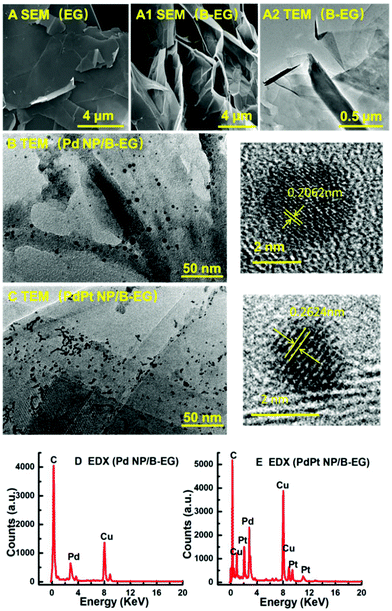
These 3D catalyst systems consist of EG or B-EG as the 3D support and Pd or PdPt bimetal NPs as the catalysts. Fig. 1A shows the SEM image of B-EG, revealing more folds and a lamellar structure. Its TEM image (Fig. 1A1) further shows that it actually consists of many thin layers that are stacked to form a porous and 3D structure. Different from smooth EG plates (Fig. 1A2), such a porous and 3D B-EG is thus expected to have a large specific surface area that is useful to load the catalysts of Pd or PdPt NPs. The TEM images of B-EG after further decoration with Pd and PdPt NPs are shown in Fig. 1B and C, respectively. More and bigger metal clusters are seen when PdPt NPs are loaded. To observe the morphology and crystallinity clearly, high-resolution TEM images of more than 100 nanoparticles have been recorded. The diameter of Pd NPs has been averaged to be about 4.1 ± 0.1 nm and the lattice fringe of these Pd NPs is 0.206 nm. For PdPt NPs, their size is smaller and is only about 2.1 ± 0.1 nm. Their lattice fringe is 0.262 nm. In the EDX spectrum for the clusters of Pd-NP/B-EG (Fig. 1D), the signals of Pd and C elements are clearly seen. The signals of Cu element are from the substrate used for EDX measurements. In the case of PdPt-NP/B-EG (Fig. 1E), the signals for Pt element are seen, besides these signals for Pd and C elements. From the integrated areas of two elements in this spectrum, the calculated mass ratio of Pd element to Pt one shown in Fig. 1(E) is approximately equal to 1![[thin space (1/6-em)]](https://www.rsc.org/images/entities/char_2009.gif) :
:![[thin space (1/6-em)]](https://www.rsc.org/images/entities/char_2009.gif) 1.
1.
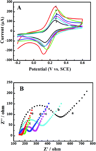
The electrochemical interfacial properties of these 3D catalyst systems were studied after being coated on a GCE. A redox couple of Fe(CN)63−/4− was employed as the probe. Fig. 2A shows the obtained cyclic voltammograms on a GCE before and after being coated with Pd-NP/EG catalysts or by different Pd-NP/B-EG catalysts. On all electrodes, a pair of well-defined redox waves is seen, obviously originating from the redox reaction of Fe(CN)63− + e− ↔ Fe(CN)64−. Compared with those of peak currents obtained on a GCE, the magnitudes of redox peak currents on modified electrodes are much enhanced. The highest peak current (206.4 μA) is found on a Pd-NP(30%)/B-EG/CGE, bigger than that on a GCE (119 μA), an EG/GCE (127 μA), a Pd-NP(30%)/EG/CGE (142 μA), a Pd-NP(20%)/B-EG/CGE (160 μA), and a Pd-NP(40%)/B-EG/CGE (197 μA). Therefore, the conductivity difference of EG from B-EG as well as the varied amount of Pd NPs determine the magnitudes of the peak currents. In other words, B-EG and a percentage of 30% Pd NPs appear the best to form such 3D catalyst systems.
Moreover, the peak currents on all electrodes are proportional to the square roots of scan rates, indicating diffusion-controlled electrode processes. According to the Randles–Sevcik equation, the calculated active surface area is 0.107, 0.114, 0.128, 0.142, 0.186, and 0.177 cm2 for a GCE, a EG/GCE, a Pd-NP(30%)/EG/GCE, a Pd-NP(20%)/B-EG/GCE, a Pd-NP(40%)/B-EG/GCE, and a Pd-NP(30%)/B-EG/GCE, respectively. A Pd-NP(30%)/B-EG/GCE exhibits the biggest surface area among these electrodes, suggesting that more Pd atoms are exposed to the solution. Therefore, its catalytic ability towards liquid fuels is expected to be higher than other electrodes.
The interfacial properties of these electrodes were further analysed using electrochemical impedance spectroscopy. The recorded Nyquist plots are shown in Fig. 2B. The linear phases in the low frequency ranges correlate with the diffusion processes, while the semicircles at high frequency ranges correspond to the electron transfer limited processes. Judged from the diameters of these semi-circles, the introduction of EG, Pd-NP/EG or Pd-NP/B-EG catalysts reduces the electron transfer resistances (Rct) of these interfaces. The value of Rct follows the order of GCE (390 Ω) > EG/GCE (216 Ω) > Pd-NP/EG/GCE (133 Ω) > Pd-NP(20%)/B-EG/GCE (107 Ω) > Pd-NP(40%)/B-EG/GCE (39 Ω) > Pd-NP(30%)/B-EG/GCE (52 Ω). The reduction of Rct on the modified GCEs in comparison with that on a GCE results from the addition of highly conductive graphite and in some cases active centres from Pd NPs. Then the electrode surface areas are enlarged and more reactive sites are provided. Such an order demonstrates the fastest electron transfer process of Fe(CN)63− + e− ↔ Fe(CN)64− on a Pd-NP(30%)/B-EG/GCE. A Pd-NP(30%)/B-EG/GCE is the best among these investigated electrode systems. It thus has been further utilized to investigate the electrocatalytic oxidation of formic acid and methanol.
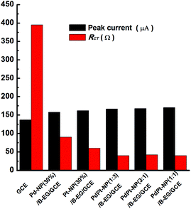
These properties were also examined when PdPt bimetal catalysts were applied to modify GCEs. Related cyclic voltammograms and Nyquist plots were recorded under the identified conditions as shown in Fig. 2. Fig. 3 compares the values of peak currents estimated from their cyclic voltammograms and Rct obtained from their Nyquist plots. For a GCE, the peak current and Rct are 119 μA and 389 Ω, respectively. They are changed to 158 μA and 90 Ω, 162 μA and 60 Ω, 167 μA and 40 Ω, 168 μA and 42 Ω, 170 μA and 40 Ω when a Pd-NP(30%)/B-EG/GCE, a Pt-NP(30%)/B-EG/GCE, a PdPt-NP(1![[thin space (1/6-em)]](https://www.rsc.org/images/entities/char_2009.gif) :
:![[thin space (1/6-em)]](https://www.rsc.org/images/entities/char_2009.gif) 3)/B-EG/GCE, a PdPt-NP(3
3)/B-EG/GCE, a PdPt-NP(3![[thin space (1/6-em)]](https://www.rsc.org/images/entities/char_2009.gif) :
:![[thin space (1/6-em)]](https://www.rsc.org/images/entities/char_2009.gif) 1)/B-EG/GCE, and a PdPt-NP(1
1)/B-EG/GCE, and a PdPt-NP(1![[thin space (1/6-em)]](https://www.rsc.org/images/entities/char_2009.gif) :
:![[thin space (1/6-em)]](https://www.rsc.org/images/entities/char_2009.gif) 1)/B-EG/GCE is employed, respectively. The increase of the magnitudes of redox currents and the reduction of Rct are found once single Pt NPs, Pd NPs, or PdPt bimetal NPs are introduced. The catalyst systems using bimetal PdPt NPs are superior to those only using single Pd or Pt NPs. However, in the catalyst systems using PdPt bimetal NPs with different mass ratios, the obtained peak currents and the values of Rct are quite close to each other, probably due to the fast faradaic process of Fe(CN)63− + e− ↔ Fe(CN)64− on these surfaces. To reduce the cost during the preparation of these catalyst systems, a PdPt-NP(1
1)/B-EG/GCE is employed, respectively. The increase of the magnitudes of redox currents and the reduction of Rct are found once single Pt NPs, Pd NPs, or PdPt bimetal NPs are introduced. The catalyst systems using bimetal PdPt NPs are superior to those only using single Pd or Pt NPs. However, in the catalyst systems using PdPt bimetal NPs with different mass ratios, the obtained peak currents and the values of Rct are quite close to each other, probably due to the fast faradaic process of Fe(CN)63− + e− ↔ Fe(CN)64− on these surfaces. To reduce the cost during the preparation of these catalyst systems, a PdPt-NP(1![[thin space (1/6-em)]](https://www.rsc.org/images/entities/char_2009.gif) :
:![[thin space (1/6-em)]](https://www.rsc.org/images/entities/char_2009.gif) 1)/B-EG/GCE was utilized and compared during catalytic tests.
1)/B-EG/GCE was utilized and compared during catalytic tests.
Performance of 3D catalyst systems
To find out the best catalyst system for the electrocatalytic oxidation of liquid fuels, several series of experiments were conducted. The electrocatalytic oxidation performance of formic acid was first investigated on 3D catalyst systems that only have the catalysts of Pd NPs. Then, electrocatalytic methanol oxidation was conducted in 3D catalyst systems based on PdPt bimetal NPs.Fig. 4 shows the cyclic voltammograms of formic acid on 3D catalyst systems that consist of varied amounts of Pd NPs and EG or B-EG. Similar electrocatalytic oxidation behaviour of formic acid is seen in four catalyst systems, where two oxidation peaks are clearly observed in the forward potential scans. The first oxidation peak comes from the direct oxidation of formic acid (dehydrogenation). The second and relatively stable oxidation peak originates from indirect oxidation of formic acid (dehydration).14 The peak current of the first oxidation peak is significantly higher than that of the second one, indicating that the electrocatalytic oxidation of formic acid in these catalyst systems is mainly controlled by the direct oxidation of formic acid. In alkaline media, the reaction steps of the electrocatalytic oxidation of formic acid in these 3D catalyst systems probably occurs in the following manner:17
| HCOOH + OH− → HCOO− + H2O | (1) |
| Pd + OH− → Pd-OHads + e− | (2) |
| 2Pd + HCOO− → Pd-Hads + Pd (COO−)ads | (3) |
| Pd(COO−)ads + 2OH− → CO32− + Pd + H2O + e− | (4) |
| Pd-OHads + Pd-Hads → 2Pd + H2O | (5) |
| HCOOH + 4OH− → CO32− + 3H2O + 2e− | (6) |
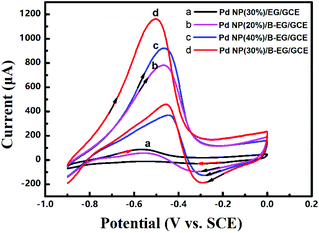 | ||
| Fig. 4 Cyclic voltammograms of 0.05 M HCOOH in 1.5 M KOH at a scan rate of 100 mV s−1 on a Pd-NP(30%)/EG/GCE (a), a Pd-NP(20%)/B-EG/GCE (b), a Pd-NP(40%)/B-EG/GCE (c), and a Pd-NP(30%)/B-EG/GCE (d). | ||
Moreover, the loading mass ratio of Pd NPs to B-EG has an obvious influence on the catalytic oxidation peak current (Fig. 4b, c and d). The obtained peak current on a Pd-NP(30%)/B-EG/GCE is as high as 1037 μA (Fig. 4d), ten times higher than that on a Pd-NP(30%)/EG/GCE (Fig. 4a). Furthermore, the initial peak potential for the electrocatalytic oxidation of formic acid shifts to −0.47 V on a Pd-NP(30%)/B-EG/GCE (Fig. 4d), the most negative value in comparison with that obtained on other catalyst systems. These results confirm that B-EG based catalyst systems are more favourable for the electrocatalytic oxidation of formic acid. A Pd-NP(30%)/B-EG catalyst system exhibits the best performance for the electrocatalytic oxidation of formic acid. This probably results from a high conductivity of B-EG and an enhanced amount of catalytic activity sites (namely exposed Pd atoms) on the surface of 3D B-EG.
Prior to the stability test of these 3D catalyst systems (shown in Fig. 4), the experimental conditions that influenced their performance towards the electrocatalytic oxidation of formic acid were optimized, covering the concentration of KOH solution, the concentration of the used Pd-NP(30%)/B-EG suspension, and the volume of the dropped suspension. During optimal experiments, the electrocatalytic oxidation of 0.05 M formic acid was studied on the Pd-NP (30%)/B-EG/GCEs under varied conditions. For example, an increase of CKOH from 0.5, 1.0, 1.5, 2.0, to 2.5 M led to a negative shift of the oxidation peak potential of formic acid in the forward scan. The biggest oxidation peak current was obtained in a KOH solution with a concentration of 1.5 M. This is because the concentration of KOH (CKOH) changes the ionization status of formic acid as well as the amount of OH− adsorbed on the catalyst surface. With respect to the concentration of the Pd-NP(30%)/B-EG suspension, it was altered from 1 to 6 mg ml−1. The obtained oxidation peak current of formic acid in the forward scan was the highest when the concentration of the Pd-NP(30%)/B-EG suspension was 4 mg ml−1. As for the volume of the Pd-NP(30%)/B-EG suspension cast onto a CCE, the oxidation peak current of formic acid in the forward scan increased once the volume was up to 7 μL and then started to descend when the volume was further increased. Consequently, a Pd-NP(30%)/B-EG suspension with a concentration of 4 mg ml−1 and a volume of 7 μL was employed to fabricate the Pd-NP(30%)/B-EG/GCEs for the investigation of the electrocatalytic oxidation of formic acid dissolved in 1.5 M KOH solution.
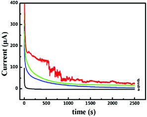
The long-term stability and toxicity resistance of these 3D catalyst systems towards the electrocatalytic oxidation of formic acid were tested. The current–time curves recorded at −0.45 V for 2500 s are shown in Fig. 5. The polarization currents on all catalyst systems decrease rapidly at the beginning of the timing, mainly due to the surface charging effect. The decay tendency of currents in the following time zone is fully different for different catalyst systems. For the system of Pd-NP(30%)/EG (Fig. 5a), the current touches zero very quickly. In contrast, when the systems of Pd-NP/B-EG catalyst systems (Fig. 5b, c and d) are utilized, the decay of the currents is much slow. In the measured time range, no zero current is seen, indicating their long-term stability towards the electrocatalytic oxidation of formic acid. In the Pd-NP(30%)/B-EG catalytic system, the highest current and the slowest current-decay rate are seen. The noise seen on the Pd-NP(30%)/B-EG catalyst indicates a fast oxidation process. In conclusion, the Pd-NP(30%)/B-EG catalyst system displays much higher catalytic ability and longer stability towards the electrocatalytic oxidation of formic acid.
Together with the best catalyst system (namely a Pd-NP(30%)/B-EG/GCE) for the electrocatalytic oxidation of formic acid, electrocatalytic methanol oxidation was then examined using a 3D catalyst system based on PdPt bimetal catalysts and EG or B-EG. Before these measurements, the applied experiment conditions were optimized. Taking a PdPt-NP(1![[thin space (1/6-em)]](https://www.rsc.org/images/entities/char_2009.gif) :
:![[thin space (1/6-em)]](https://www.rsc.org/images/entities/char_2009.gif) 1)/B-EG/GCE as an example, the optimal experimental conditions for electrocatalytic methanol oxidation were: a suspension of 4 mg ml−1 PdPt-NP(1
1)/B-EG/GCE as an example, the optimal experimental conditions for electrocatalytic methanol oxidation were: a suspension of 4 mg ml−1 PdPt-NP(1![[thin space (1/6-em)]](https://www.rsc.org/images/entities/char_2009.gif) :
:![[thin space (1/6-em)]](https://www.rsc.org/images/entities/char_2009.gif) 1)/B-EG, a volume of 5μL PdPt-NP(1
1)/B-EG, a volume of 5μL PdPt-NP(1![[thin space (1/6-em)]](https://www.rsc.org/images/entities/char_2009.gif) :
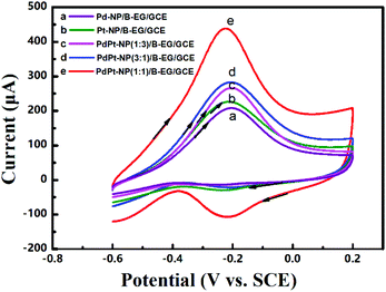
:![[thin space (1/6-em)]](https://www.rsc.org/images/entities/char_2009.gif) 1)/B-EG suspension, and a 1.5 M KOH solution. The cyclic voltammograms for electrocatalytic methanol oxidation in these 3D catalyst systems are shown in Fig. 6. Two typical anodic waves are noticed on all catalyst systems. The oxidation peak with the peak potential at −0.20 V in the forward scan results from the direct oxidation of methanol, while the second one with the peak potential at −0.39 V in the reverse scan originates from the oxidation of the incomplete oxidation products formed during the forward scan.18 In alkaline media, the reaction of electrocatalytic methanol oxidation in this PdPt-NP(1
1)/B-EG suspension, and a 1.5 M KOH solution. The cyclic voltammograms for electrocatalytic methanol oxidation in these 3D catalyst systems are shown in Fig. 6. Two typical anodic waves are noticed on all catalyst systems. The oxidation peak with the peak potential at −0.20 V in the forward scan results from the direct oxidation of methanol, while the second one with the peak potential at −0.39 V in the reverse scan originates from the oxidation of the incomplete oxidation products formed during the forward scan.18 In alkaline media, the reaction of electrocatalytic methanol oxidation in this PdPt-NP(1![[thin space (1/6-em)]](https://www.rsc.org/images/entities/char_2009.gif) :
:![[thin space (1/6-em)]](https://www.rsc.org/images/entities/char_2009.gif) 1)/B-EG catalyst system probably involves the following steps:18–21
1)/B-EG catalyst system probably involves the following steps:18–21
| CH3OH + Pt → Pt-COads + H+ | (7) |
| Pd + OH− → Pd-(OH)ads + e− | (8) |
| Pt-COads + Pd-(OH)ads → PtPd + CO2 + H+ + e− | (9) |
| CO2 + 2OH− → CO32− + H2O | (10) |
The oxidation peak potentials in all the catalyst systems are very close while the oxidation peak currents varied significantly. The highest oxidation peak currents are seen on a PdPt-NP(1![[thin space (1/6-em)]](https://www.rsc.org/images/entities/char_2009.gif) :
:![[thin space (1/6-em)]](https://www.rsc.org/images/entities/char_2009.gif) 1)/B-EG/GCE for both oxidation reactions. Such currents were bigger and more stable for 2500 s than those obtained in other systems, as confirmed from the same measurements shown in Fig. 5. Therefore, a PdPt-NP(1
1)/B-EG/GCE for both oxidation reactions. Such currents were bigger and more stable for 2500 s than those obtained in other systems, as confirmed from the same measurements shown in Fig. 5. Therefore, a PdPt-NP(1![[thin space (1/6-em)]](https://www.rsc.org/images/entities/char_2009.gif) :
:![[thin space (1/6-em)]](https://www.rsc.org/images/entities/char_2009.gif) 1)/B-EG catalyst system displays better catalytic ability and more durability towards electrocatalytic methanol oxidation.
1)/B-EG catalyst system displays better catalytic ability and more durability towards electrocatalytic methanol oxidation.
Conclusions
In summary, three-dimensional catalyst systems towards stable and efficient electrocatalytic oxidation of formic acid and methanol have been synthesized using cheap expanded graphite as the three-dimensional support and cost-effective palladium nanoparticles as the catalysts. The use of boron-doped expanded graphite and palladium/platinum bimetal nanoparticles further improves the catalytic performance of these three-dimensional catalyst systems towards the electrocatalytic oxidation of liquid fuels. Further studies with respect to the details of the active sites of bimetal nanoparticles and the adsorption behaviour (e.g., site, amount, energy, etc.) of intermediates during the electrocatalytic oxidation of liquid fuels on these three-dimensional catalyst systems need to be carried out. Their further applications for the electrocatalytic oxidation of other liquid fuels are worth exploring. Higher and better catalytic ability of single palladium and/or palladium/platinum bimetal nanoparticles loaded on expanded graphite or boron-doped expanded graphite towards the electrocatalytic oxidation of methanol and other liquid fuels is expected. To conclude, this work offers a simple and cost-effective approach to synthesize stable and efficient electrocatalysts at large scales for the industrial production of direct methanol fuel cells.Conflicts of interest
There are no conflicts to declare.Acknowledgements
This work was financially supported by the National Natural Science Foundation of China (61701352).References
- B. Dunn, H. Kamath and J.-M. Tarascon, Science, 2011, 334, 928–935 CrossRef CAS PubMed.
- A. Serov, K. Artyushkova, E. Niangar, C. Wang, N. Dale, F. Jaouen and P. Atanassov, Nano Energy, 2015, 16, 293–300 CrossRef CAS.
- X. Zhao, M. Yin, L. Ma, L. Liang, C. Liu, J. Liao, T. Lu and W. Xing, Energy Environ. Sci., 2011, 4, 2736–2753 RSC.
- A. Mehmood, M. A. Scibioh, J. Prabhuram, M. G. An and H. Y. Ha, J. Power Sources, 2015, 297, 224–241 CrossRef CAS.
- N. Kakati, J. Maiti, S. H. Lee, S. H. Jee, B. Viswanathan and Y. S. Yoon, Chem. Rev., 2014, 114, 12397–12429 CrossRef CAS PubMed.
- B. Zohuri, Small Modular Reactors as Renewable Energy Sources, Springer, Cham, 2019, 37–59 Search PubMed.
- C. Wang and M. H. Nehrir, IEEE Trans. Energy Convers., 2008, 23, 957–967 Search PubMed.
- T. Wilberforce, A. Alaswad, A. Palumbo, M. Dassisti and A. G. Olabi, Int. J. Hydrogen Energy, 2016, 41, 16509–16522 CrossRef CAS.
- A. Serov and C. Kwak, Appl. Catal., B, 2009, 90, 313–320 CrossRef CAS.
- Q. Li, T. Wang, D. Havas, H. Zhang, P. Xu, J. Han and G. Wu, Adv. Sci., 2016, 3, 1600140 CrossRef PubMed.
- W. Hong, C. Shang, J. Wang and E. Wang, Energy Environ. Sci., 2015, 8, 2910–2915 RSC.
- J. Bian, M. Xiao, S. J. Wang, Y. X. Lu and Y. Z. Meng, J. Colloid Interface Sci., 2009, 334, 50–57 CrossRef CAS PubMed.
- M. Huang, J. Zhang, C. Wu and L. Guan, J. Power Sources, 2017, 342, 273–278 CrossRef CAS.
- H. Li, Y. Zhang, Q. Wan, Y. Li and N. Yang, Carbon, 2018, 131, 111–119 CrossRef CAS.
- M. L. Yola, T. Eren, N. Atar, H. Saral and I. Ermiş, Electroanalysis, 2016, 28, 570–579 CrossRef CAS.
- D. Bin, B. B. Yang, F. F. Ren, K. Zhang, P. Yang and Y. K. Du, J. Mater. Chem. A, 2015, 3, 14001–14006 RSC.
- G. Hu, F. Nitze, H. R. Barzegar, T. Sharifi, A. Mikolajczuk, C.-W. Tai, A. Borodzinski and T. Wagberg, J. Power Sources, 2012, 209, 236–242 CrossRef CAS.
- A. Maksic, Z. Rakocevic, M. Smiljanic, M. Nenadovic and S. Strbac, J. Power Sources, 2015, 273, 724–734 CrossRef CAS.
- G. Yang, Y. Zhou, H.-B. Pan, C. Zhu, S. Fu, C. M. Wai, D. Du, J.-J. Zhu and Y. Lin, Ultrason. Sonochem., 2016, 28, 192–198 CrossRef CAS PubMed.
- R. K. Pandey and V. Lakshminarayanan, J. Phys. Chem. C, 2009, 113, 21596–21603 CrossRef CAS.
- F. C. Zhu, G. S. Ma, Z. C. Bai, R. Q. Hang, B. Tang, Z. H. Zhang and X. G. Wang, J. Power Sources, 2013, 242, 610–620 CrossRef CAS.
Footnote |
| † Equally contributed. |
| This journal is © The Royal Society of Chemistry 2019 |

