A strategically managed rechargeable battery system with a neutral methyl viologen anolyte and an acidic air-cathode enabled by a mediator-ion solid electrolyte†
Xingwen
Yu
 and
Arumugam
Manthiram
 *
*
Materials Science and Engineering Program, Texas Materials Institute, The University of Texas at Austin, Austin, Texas 78712, USA. E-mail: manth@austin.utexas.edu
First published on 30th May 2018
Abstract
Redox flow batteries with organic electrode materials are attracting much attention. Previous research efforts have been focusing on liquid-phase electrodes on both the anode and cathode sides. Since batteries based on air cathodes can provide immense advantages, coupling a liquid organic electrode with a gaseous air cathode could offer multiple benefits in terms of cost, safety, and energy density. Herein we present a liquid–gaseous battery system with an aqueous methyl viologen (MV) anode and an air cathode. However, under the traditional battery operation principle with the same electrolyte at the anode and cathode, the resulting MV–air battery will not be able to provide a reasonable voltage for practical applications. In this study, the cell voltage of the MV–air chemistry is strategically manipulated by using an acidic cathode electrolyte (catholyte) and a neutral anode electrolyte (anolyte). To operate a battery with different electrolytes at the anode and cathode, a sodium-ion (Na+-ion) conductive solid-state electrolyte (Na-SSE) membrane is employed to physically and electrically separate the two electrodes. The shuttling of sodium ions via the Na-SSE balances the ionic charge transfer between the two electrodes and sustains the redox reactions at the air cathode and the MV anode.
Introduction
Redox flow batteries are considered as a viable electrochemical energy storage technology to efficiently utilize clean energy harvested from renewable resources, such as wind and solar.1,2 However, due to a series of challenges, such as crossover of active materials between the two electrodes through the conventional ion-exchange separators leading to a lower efficiencies, cost, and chemical toxicity, a widespread implementation of conventional redox flow batteries is still limited.3–5 To achieve the goal of cost-effective, environmentally benign, safe energy storage systems, recent research in redox flow batteries has tended to shift from inorganic electrode materials to organic electrode materials.6–11 To date, most of the organic redox flow batteries have been developed with liquid-phase electrodes on both the anode and cathode sides.12–15 Interestingly, electrochemical cells with an air cathode can offer a sequence of technological advantages, such as reducing the volume, weight, and cost of the battery systems. With the use of free O2 from the atmosphere, the above technical merits can be easily achieved.16–21 However, metal-based anodes have been the main focus in the literature to couple with the air cathode to develop metal–air batteries.22–25 Rechargeable batteries with organic liquid-air chemistries have sparsely been reported.In this study, we present a new battery chemistry with a liquid-phase organic anode (methyl viologen, MV) and a gas-phase air cathode. To achieve a practically acceptable cell voltage, the MV–air battery is strategically developed with an acidic cathode electrolyte (catholyte) and a neutral anode electrolyte (anolyte). The catholyte and anolyte with different pH values are physically and electrically separated with a mediator-ion (Na+-ion) solid-state electrolyte (Na-SSE) membrane. The Na+-ions migrate back and forth through the Na-SSE during charge–discharge, acting as an ionic messenger to maintain the ionic charge balance between the two electrodes.
Results and discussion
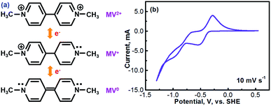
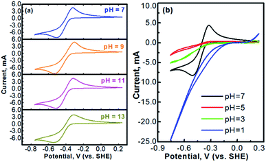
Methyl viologen (MV), which is N,N′-dimethyl-4,4′-bipyridinium dichloride ([(C6H7N)2]Cl2), is an electrochemically active organic material. It has recently been pursued as a liquid-phase electrode material in aqueous solutions.26,27 Methyl viologen mainly exists in three oxidation states, MV0, MV+, and MV2+.28,29 The transition between MV2+ and MV+ as well as that between MV+ and MV0 involves one-electron transfer in each process.30–32 Redox reactions of the methyl viologen species are as schematized in Fig. 1a. A cyclic voltammetry (CV) profile of a platinum electrode in a solution containing 0.1 M [(C6H7N)2]Cl2 and 0.5 M Na2SO4 (serves as a supporting electrolyte) is presented in Fig. 1b. The two reduction waves at ca. −0.52 V and ca. −0.95 V correspond, respectively, to the reduction of MV2+ to MV+ and that of MV+ to MV0.33,34 For the anodic process, the two oxidation waves at ca. −0.66 V and ca. −0.27 V correspond, respectively, to the oxidation of MV0 to MV+ and that of MV+ to MV2+. It can be seen that the first-step redox reaction of MV2+ ↔ MV+ is highly reversible. However, the reversibility of the second-step reaction of MV+ ↔ MV0 is relatively poor. According to the previous fundamental studies, the transition process of MV+ ↔ MV0 is actually electrochemically reversible.35 However, the poor reversibility of the MV+ ↔ MV0 couple in aqueous solution, as observed in Fig. 1b, is most likely due to the poor solubility and the uncharged feature of the MV0 species.35 Therefore, the electrochemical transition reaction between the MV2+ and the MV+ species will be an ideal redox couple for the development of redox flow batteries.Fig. 2 presents the cyclic voltammograms of the redox reaction of MV2+ ↔ MV+ in 0.1 M [(C6H7N)2]Cl2 + 0.5 M Na2SO4 solutions with different pH values. As seen in Fig. 2a, under neutral or alkaline conditions, the transition reaction of MV2+/MV+ is highly reversible without any significant side reactions. The redox potential of MV2+/MV+ is almost identical at the pH values of 7 to 13. However, as seen in Fig. 2b, the reversibility of the MV2+/MV+ reaction is poor under acidic conditions. It is almost irreversible at low pH values. Therefore, the methyl viologen can only be used as an electrochemically active electrode under the neutral or alkaline conditions.
The electrochemistry of oxygen reduction reaction (ORR) has been well established.36,37 Redox reactions and the corresponding redox potentials of oxygen under acidic and alkaline conditions are expressed, respectively, as eqn (1) and (2).
| O2 + 4H+ + 4e−↔ 2H2O, E0 = 1.23 V vs. SHE | (1) |
| O2 + 2H2O ↔ 4OH− + 4e−, E0 = 0.40 V vs. SHE | (2) |
According to the data presented in Fig. 2a, the redox potential of MV2+/MV+ under a neutral or an alkaline condition is ca. −0.4 V (vs. SHE). Therefore, if an MV - air cell is operated under the traditional principle with the same alkaline or neutral electrolyte at both the anode and cathode, the theoretical voltage of the resulting cell will be 0.8 V. The cell voltage will be even lower under the practical cell working conditions at higher current densities. Such a low voltage makes the MV–air cell unable to meet the practical application demand as an electrochemical energy storage system.
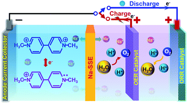
However, if the MV–air cell is operated with a neutral or alkaline MV anode and an acidic air cathode, a reasonably high theoretical cell voltage (ca. 1.6 V) can be achieved. Unfortunately, under the conventional cell operation principle by employing a porous separator, it would not allow developing such a dual-electrolyte cell. The acidic cathode electrolyte and the neutral anode electrolyte would mix with each other during cell operation. Herein, we strategically operate the MV–air cell with an acidic cathode electrolyte (catholyte) and a neutral anode electrolyte (anolyte). The catholyte and anolyte with different pH values are physically and electrically separated with a sodium-ion (Na+-ion) conductive solid-state electrolyte (Na-SSE) membrane, as schematized in Fig. 3. The redox reactions at the acidic air cathode and the neutral MV anode are sustained by the migration of Na+-ions as an ionic messenger through the Na-SSE. To minimize the overpotential of the oxygen redox reaction at the positive electrode, a decoupled positive electrode configuration was applied to the MV–air cell by employing a Ti supported IrO2 (IrO2/Ti) catalyst for the oxygen evolution reaction (OER) and a Pt/C (carbon supported platinum) catalyst for the oxygen reduction reaction (ORR). The as such fabricated cell is termed as MV (neutral)‖Na-SSE‖air (acid).
During the charge of an MV (neutral)‖Na-SSE‖air (acid) cell, H2O is oxidized to O2 on the IrO2/Ti OER catalyst. This process releases four electrons to the external circuit and releases four protons into the catholyte. At the anode, the [(C6H7N)2]Cl2 (MV2+) is reduced to [(C6H7N)2]Cl (MV+) by obtaining electrons via the external circuit. This process also releases a Cl− ion in the anolyte. In order to balance the ionic charge transfer between the catholyte and anolyte, sodium ions migrate via the Na-SSE from the cathode electrolyte to the anode electrolyte and couple with the released Cl− ions. During the discharge process, the reactions are reversed. At the anode, the [(C6H7N)2]Cl (MV+) is oxidized to [(C6H7N)2]Cl2 (MV2+) by combining with the Cl− ions and releasing one electron to the external circuit while the Na+-ions diffuse back to the cathode electrolyte through the Na-SSE. At the cathode, the O2 is reduced to water on the Pt/C ORR catalyst by receiving electrons from the external circuit.
The electrochemical kinetics of the MV2+/MV+ redox reaction was further studied with CV experiments. Fig. 4a shows the CV profiles of the platinum electrode in a solution containing 0.1 M [(C6H7N)2]Cl2 and 0.5 M Na2SO4 at different scan rates. At each scan rate, the electrochemical process of the MV2+/MV+ is perfectly reversible. Peak current densities (Ipeak) as a function of the square root of scan rate (ν1/2) for the cathodic (MV2+ → MV+) and the anodic (MV+ → MV2+) reactions are, respectively, summarized in Fig. 4b and c. The data were derived from Fig. 4a. In both the cathodic and the anodic cases, the Ipeakvs. V1/2 shows a perfect linear relationship. This implies that either the reduction of MV2+ or the oxidation of MV+ is a mass-transport control process. Therefore, the diffusion coefficients of MV2+ and MV+ species can be calculated according to the Randles–Sevcik equation.38,39
| Ip = 269000SD1/2n3/2ν1/2C | (3) |
The sodium mediator-ion SSE employed in this study is a NASICON-type material with a composition of Na3Zr2Si2PO12. This material exhibits a sodium-ion conductivity of ca. 1.0 × 10⁻³ S. cm−1 at room temperature.42 To ensure a high surface area for accommodating the liquid MV2+ and MV+ active electrode materials, a piece of carbon cloth purchased from the Fuel Cell Store was used as the anode matrix. A picture and a scanning electron microscope (SEM) image showing the high surface fabric of the carbon cloth are provided in Fig. S1.† The IrO2/Ti OER catalyst was prepared by depositing a thin layer of IrO2 on the surface of Ti mesh as described in the experimental procedure of the ESI.† A picture, as well as an SEM image of the IrO2/Ti OER catalyst, are provided in Fig. S2.†
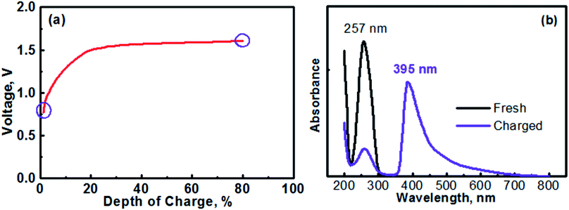
The anolyte of this study was prepared with 0.1 M [(C6H7N)2]Cl2 + 0.5 M Na2SO4. Therefore, the MV (neutral)‖Na-SSE‖air (acid) cell was actually assembled in the discharge state. It should be noted that toward practical applications, high-concentration anolyte would be preferred in order to achieve a high energy density with the cell. However, in this proof-of-concept study, the cell was operated with a relatively low-concentration anolyte to avoid any solubility limitation problems. Effects of the concentration of anolyte on the cell performances will be systematically studied in the future. Fig. 5a shows the initial charge profile of the MV (neutral)‖Na-SSE‖air (acid) cell. In order to avoid the formation of insoluble MV0, the cell was charged to a depth of 80% on the basis of the theoretical capacity of the MV2+/MV+ redox couple. Therefore, there does not appear a rising point in the first charge profile in Fig. 5a. To confirm the transition of MV2+ to MV+, the charge product of the anolyte was analyzed with ultraviolet-visible spectroscopy (UV-Vis). Fig. 5b shows the UV-Vis spectra of the fresh [(C6H7N)2]Cl2 anolyte and after being charged to a depth of 80%, as indicated by the purple circles in Fig. 5a. The absorption peaks located at 257 nm is attributed to the MV2+ species.43,44 The appearance of an absorption peak at 395 nm in the spectrum of the charged anolyte indicates the formation of MV+.43 The absorbance of the MV2+ peak for the charged anolyte is ca. 22% of that for the fresh [(C6H7N)2]Cl2 anolyte, indicating ca. 78% of the MV2+ species has been reduced to the MV+. This result is consistent with the assigned depth of charge of the MV (neutral)‖Na-SSE‖air (acid) cell. The transition of MV2+ to MV+ can also be visually observed since there is a color change upon the reduction of the MV2+ species.45,46 Fig. S3† presents the color change of the anolyte during charging an MV (neutral)‖Na-SSE‖air (acid) cell. For the convenience of observation, the anolyte chamber was specially designed with a crescent-shape grove in the lower right corner and a piece of Ti mesh (rather than the high-surface carbon cloth) was used as the anode current collector. As seen in Fig. S3,† the fresh anolyte is colorless before charging. After the cell was charged for 1 h at a current density of 1.0 mA cm−2, the anolyte exhibits a violet color. After charging for 2 h, the color of anolyte became even darker.
Fig. 6 presents the cycling performances of the MV (neutral)‖Na-SSE‖air (acid) cell. The cell was operated with a separate OER electrode and ORR electrode, as described in the experimental section of ESI.† The charge and discharge profiles were individually recorded with two separate channels on a battery testing instrument. A 5 minute resting time was preset between each charge and discharge period. Fig. 6a presents the voltage polarization curves of the MV (neutral)‖Na-SSE‖air (acid) cell. Upon applying a charge–discharge current, the cell voltage responds accordingly. As seen in Fig. 6a, the charge voltage of the cell increases and the discharge voltage decreases with the increase in the cycling current. The high polarization behavior of the cell is mostly due to the relatively low Na+-ion conductivity of the Na-SSE and the relatively high thickness (ca. 0.7 mm) of the Na-SSE membrane used for the fabrication of the cell. Reducing the thickness of the Na-SSE pellet with proper techniques is underway in our lab. Upon being able to fabricate a thin SSE membrane, the MV (neutral)‖Na-SSE‖air (acid) cell will be able to be cycled at high current densities. Fig. 6b shows the consecutive charge–discharge profile of the MV (neutral)‖Na-SSE‖air (acid) cell at a cycling current density of 1.0 mA cm−2. The consecutive charge–discharge curves of the cell operated at other current densities are provided in Fig. S4.† As seen in Fig. 6b and S4,† the cycling profiles show consistent charge and discharge voltages throughout the 50 cycles. There does not appear to be significant changes in the voltage polarization with a continuous cycling of the cell. Fig. S5† shows an SEM image of a cycled (after 50 cycles) carbon cloth matrix. In comparison to the fresh electrode (Fig. S1†), there is no obvious change observed in terms of the integrity of the carbon fiber. The stable cycling performance also indicates that different liquid electrolytes at the anode and the cathode are completely separated by the Na-SSE and the electrochemical reactions at the two electrodes are effectively mediated by the shuttling of the sodium ions.
Conclusions
In summary, this study has demonstrated an electrochemical energy storage system with a novel methyl viologen–air (O2) chemistry that is enabled by a mediator-ion solid electrolyte strategy. Operation of the cell with an acidic cathode electrolyte (catholyte) and a neutral anode electrolyte (anolyte) offers a reasonable cell voltage. Under the mediator-ion operating principle, the neutral anolyte and the acidic catholyte are electrically and physically separated by a Na+-ion conductive solid-state electrolyte (Na-SSE) membrane. The sodium ions shuttling through the solid-state electrolyte act as ionic mediator to maintain the ionic charge balance between the two electrodes and to maintain the redox reactions at the cathode and anode.Conflicts of interest
There are no conflicts of interest to declare.Acknowledgements
This work was supported by the U.S. Department of Energy, Office of Basic Energy Sciences, Division of Materials Sciences and Engineering under award number DE-SC0005397.Notes and references
- G. L. Soloveichik, Chem. Rev., 2015, 115, 11533–11558 CrossRef PubMed.
- L. J. Li and A. Manthiram, Adv. Energy Mater., 2016, 6, 1502054 CrossRef.
- A. Manthiram, X. Yu and S. Wang, Nat. Rev. Mater., 2017, 2, 16103 CrossRef.
- P. Alotto, M. Guarnieri and F. Moro, Renewable Sustainable Energy Rev., 2014, 29, 325–335 CrossRef.
- X. W. Yu, M. M. Gross, S. F. Wang and A. Manthiram, Adv. Energy Mater., 2017, 7, 1602454 CrossRef.
- J. Winsberg, T. Hagemann, T. Janoschka, M. D. Hager and U. S. Schubert, Angew. Chem., Int. Ed., 2017, 56, 686–711 CrossRef PubMed.
- X. L. Wei, W. X. Pan, W. T. Duan, A. Hollas, Z. Yang, B. Li, Z. M. Nie, J. Liu, D. Reed, W. Wang and V. Sprenkle, ACS Energy Lett., 2017, 2, 2187–2204 CrossRef.
- M. Park, J. Ryu, W. Wang and J. Cho, Nat. Rev. Mater., 2017, 2, 16080 CrossRef.
- C. M. Araujo, D. L. Simone, S. J. Konezny, A. Shim, R. H. Crabtree, G. L. Soloveichik and V. S. Batista, Energy Environ. Sci., 2012, 5, 9534–9542 Search PubMed.
- C. S. Sevov, R. E. M. Brooner, E. Chenard, R. S. Assary, J. S. Moore, J. Rodriguez-Lopez and M. S. Sanford, J. Am. Chem. Soc., 2015, 137, 14465–14472 CrossRef PubMed.
- X. W. Yu and A. Manthiram, Joule, 2017, 1, 453–462 CrossRef.
- B. Huskinson, M. P. Marshak, C. Suh, S. Er, M. R. Gerhardt, C. J. Galvin, X. D. Chen, A. Aspuru-Guzik, R. G. Gordon and M. J. Aziz, Nature, 2014, 505, 195–198 CrossRef PubMed.
- T. Janoschka, N. Martin, U. Martin, C. Friebe, S. Morgenstern, H. Hiller, M. D. Hager and U. S. Schubert, Nature, 2015, 527, 78–81 CrossRef PubMed.
- B. Hu, C. DeBruler, Z. Rhodes and T. L. Liu, J. Am. Chem. Soc., 2017, 139, 1207–1214 CrossRef PubMed.
- W. Wang and V. Sprenkle, Nat. Chem., 2016, 8, 204–206 CrossRef PubMed.
- A. C. Luntz and B. D. McCloskey, Chem. Rev., 2014, 114, 11721–11750 CrossRef PubMed.
- Y. G. Li and H. J. Dai, Chem. Soc. Rev., 2014, 43, 5257–5275 RSC.
- P. Gu, M. B. Zheng, Q. X. Zhao, X. Xiao, H. G. Xue and H. Pang, J. Mater. Chem. A, 2017, 5, 7651–7666 Search PubMed.
- Y. G. Li and J. Lu, ACS Energy Lett., 2017, 2, 1370–1377 CrossRef.
- L. J. Li and A. Manthiram, Nano Energy, 2014, 9, 94–100 CrossRef.
- L. J. Li, S. H. Chai, S. Dai and A. Manthiram, Energy Environ. Sci., 2014, 7, 2630–2636 Search PubMed.
- N. Imanishi and O. Yamamoto, Mater. Today, 2014, 17, 24–30 CrossRef.
- J. Fu, Z. P. Cano, M. G. Park, A. P. Yu, M. Fowler and Z. W. Chen, Adv. Mater., 2017, 29, 1604685 CrossRef PubMed.
- Z. Ma, X. X. Yuan, L. Li, Z. F. Ma, D. P. Wilkinson, L. Zhang and J. J. Zhang, Energy Environ. Sci., 2015, 8, 2144–2198 Search PubMed.
- D. Zhang, C. Z. Zhang, D. B. Mu, B. R. Wu and F. Wu, Prog. Chem., 2012, 24, 2472–2482 Search PubMed.
- Y. Ding and G. H. Yu, Angew. Chem., Int. Ed., 2017, 56, 8614–8616 CrossRef PubMed.
- B. Hu, C. Seefeldt, C. DeBruler and T. L. Liu, J. Mater. Chem. A, 2017, 5, 22137–22145 Search PubMed.
- I. Shpilevaya and J. S. Foord, Electroanal, 2014, 26, 2088–2099 CrossRef.
- J. R. White and A. J. Bard, J. Electroanal. Chem., 1986, 197, 233–244 CrossRef.
- P. M. S. Monk, R. D. Fairweather, M. D. Ingram and J. A. Duffy, J. Chem. Soc., Perkin Trans. 2, 1992, 2039–2042 RSC.
- A. Walcarius, L. Lamberts and E. G. Derouane, Electroanal, 1995, 7, 120–128 CrossRef.
- O. Enea, Electrochim. Acta, 1986, 31, 789–793 CrossRef.
- T. W. Hui and M. D. Baker, J. Phys. Chem. B, 2002, 106, 827–832 CrossRef.
- I. Okura, S. Nakamura, N. Kimthuan and K. I. Nakamura, J. Mol. Catal., 1979, 6, 261–267 CrossRef.
- C. L. Bird and A. T. Kuhn, Chem. Soc. Rev., 1981, 10, 49–82 RSC.
- H. Y. Yuan, Y. Hou, I. M. Abu-Reesh, J. H. Chen and Z. He, Mater. Horiz., 2016, 3, 382–401 RSC.
- T. J. Schmidt, V. Stamenkovic, P. N. Ross and N. M. Markovic, Phys. Chem. Chem. Phys., 2003, 5, 400–406 RSC.
- C. M. A. Brett and A. M. O. Brett, Electrochemistry Principles, Methods and Applications, Oxford University Press, Oxford/New York, 1993 Search PubMed.
- M. C. Henstridge, E. Laborda, E. J. F. Dickinson and R. G. Compton, J. Electroanal. Chem., 2012, 664, 73–79 CrossRef.
- Q. Q. Lin, Q. Li, C. Batchelor-McAuley and R. G. Compton, J. Electrochem. Sci. Technol., 2013, 4, 71–80 CrossRef.
- R. A. Mackay, S. A. Myers and A. BrajterToth, Electroanal, 1996, 8, 759–764 CrossRef.
- J. K. Kim, E. Lee, H. Kim, C. Johnson, J. Cho and Y. Kim, Chemelectrochem, 2015, 2, 328–332 CrossRef.
- J. F. Stargardt and F. M. Hawkridge, Anal. Chim. Acta, 1983, 146, 1–8 CrossRef.
- J. Peon, X. Tan, J. D. Hoerner, C. G. Xia, Y. F. Luk and B. Kohler, J. Phys. Chem. A, 2001, 105, 5768–5777 CrossRef.
- D. Wang, W. E. Crowe, R. M. Strongin and M. Sibrian-Vazquez, Chem. Commun., 2009, 1876–1878 RSC.
- Y. S. Park, S. Y. Um and K. B. Yoon, J. Am. Chem. Soc., 1999, 121, 3193–3200 CrossRef.
Footnote |
| † Electronic supplementary information (ESI) available: Details of experimental methods, a picture and a scanning electron microscopy (SEM) image of a piece of carbon cloth matrix, a picture and a SEM image of a piece of titanium mesh supported iridium oxide (IrO2/Ti) catalyst, color change of the anolyte during charging a MV(neutral)‖Na-SSE‖air (acid) cell, consecutive charge–discharge profiles of the MV (neutral)‖Na-SSE‖air (acid) cells at different cycling current densities, an SEM image of a carbon cloth matrix after 50 cycles, Fig. S1–S5. See DOI: 10.1039/c8se00227d |
| This journal is © The Royal Society of Chemistry 2018 |


