 Open Access Article
Nanoconfined nitrogen-doped carbon-coated MnO nanoparticles in graphene enabling high performance for lithium-ion batteries and oxygen reduction reaction†
Yinghui
Wang
,
Xing
Ding
,
Fan
Wang
,
Junqi
Li
,
Shuyan
Song
* and
Hongjie
Zhang
*
State Key Laboratory of Rare Earth Resource Utilization, Changchun Institute of Applied Chemistry, Chinese Academy of Sciences, Changchun 130022, P. R. China. E-mail: songsy@ciac.ac.cn; hongjie@ciac.ac.cn
First published on 9th March 2016
Abstract
To tackle the issues of inferior cycling stability and low conductivity for MnO as an anode material for lithium ion batteries (LIBs) and as a catalyst for oxygen reduction reaction (ORR), a facile and effective strategy is explored to confine N-doped carbon-coated MnO nanoparticles in a conductive graphene matrix. The synthesis of the GMNCs involves the two-step coating of Mn3O4 nanocrystals with polydopamine and graphene, followed by heat treatment to form the GNS@MnO@N-doped carbon composites (GMNCs). When evaluated as anode materials for LIBs, the as-prepared GMNCs exhibit an improved cycling stability (754.3 mA h g−1 after 350 cycles at 0.1 A g−1) compared to carbon-coated MnO and pure Mn3O4 due to the double carbon coating design. When evaluated as catalysts for ORR, the as-prepared GMNCs exhibit higher electrocatalytic activity than that of pure Mn3O4 and MnO catalysts, and superior stability to a commercial Pt/C catalyst due to the synergetic effect between the MnO and N-doped double carbon coating. The optimum design of the unique nanostructures with the synergetic effect provides a new route to design advanced materials as electrode/catalysts for energy conversion and storage.
Introduction
Interest in developing high-performance and environmentally-friendly energy conversion and storage systems, such as lithium ion batteries (LIBs), metal–air batteries and fuel cells, has grown significantly since it is expected to be one promising strategy to tackle the global energy crisis and environmental pollution issues.1–6 Of the energy conversion and storage systems, it is still a great challenge for LIBs to achieve high capacities, excellent cycling performance and rate capabilities for the growing power supply requirements. The most effective way to accomplish this objective is to shorten the diffusion path of the electrode materials or introduce a conductive buffering matrix.7–10 On the other hand, the major challenge associated with metal–air batteries/fuel cells is the high cost and limited supply of the catalyst for oxygen reduction reaction (ORR). To overcome this predicament, the replacement of platinum with nonprecious metal catalysts is highly desirable.11–15Transition-metal oxides have been extensively demonstrated as electrode materials and potential ORR catalysts for energy conversion and storage because of their excellent electrochemical activities, low cost, easy availability and environmental friendliness.16–18 Typically, manganese oxides (MnOx) are now renowned for their fascinating properties and potential applications. For instance, MnOx-based materials are promising anodes for LIBs because of their high densities, low conversion potentials, and high theoretical capacities (756 mA h g−1) as well as their voltage hysteresis (<0.8 V).19–21 Interestingly, they have also been widely studied as alternative ORR catalysts in alkaline solutions, because of their low cost and minimum environmental impact.22–25 However, MnOx-based materials usually suffer from two typical problems, poor durability and low electrical conductivity. On the one hand, the drastic volume change and low electrical conductivity generally result in rapid capacity fading and inferior rate performance of MnOx-based anodes.26 On the other hand, pristine MnOx materials usually exhibit limited ORR activities probably due to their low electrical conductivities.15
To resolve these problems, loading of MnOx nanoparticles into conducting carbon carriers can overcome the limitations and improve the LIB performance and ORR activity.27–30 Graphene sheets (GNS) are regarded as the most effective conducting matrix as well as a buffering substrate. Apart from improving the electrical conductivity, graphene with its large surface area and high flexibility can also act as a buffer layer to alleviate the volume variation of the active particles upon cycling.31 However, the exposed MnOx nanoparticles on the GNS surface are still prone to aggregation during the cycling, resulting in declining electrochemical performance. One solution to overcome this problem is to confine the nanoparticles within highly conductive carbon shells in the GNS to form a double conductive carbon-coated structure.32–36 Considering that N-doped carbons have considerable LIB performances and ORR activities,15,37–40 consequently, utilizing such a strategy to encapsulate MnO nanoparticles within N-doped carbon shells on GNS could achieve high electrochemical performances.
Motivated by this intriguing strategy, we confined MnO nanoparticles within N-doped double carbon shells in GNS to fabricate GNS@MnO@N-doped carbon composites (GMNCs) and explored their applications in LIBs and ORR. To the best of our knowledge, composites of GNS, N-doped carbon and MnO nanocrystals applied to both LIBs and ORR have not yet been reported. It is worth mentioning that the introduction of the carbon matrix enhances both the structure stability and electrical conductivity of MnO. Benefiting from the excellent electroconductive network, the efficient protection of the carbon shell and the synergetic effect between the MnO and N-doped carbon coating, the as-prepared GMNCs show a high electrochemical performance for LIBs and ORR.
Experimental section
Synthesis of Mn3O4@PDA nanoparticles
Mn3O4 nanocrystals were firstly synthesized using a previously reported method.41 Then, the as-obtained Mn3O4 nanocrystals were redispersed in cyclohexane (10 mL). For synthesizing the PDA-coated Mn3O4 nanoparticles (named as Mn3O4@PDA), Igepal CO-520 (0.65 mL) was added to the above solution. After vigorous stirring for 30 min, ammonium hydroxide (75 μL, 28 wt% in water) was added into the mixture using ultrasonication for 15 min. After vigorous stirring for another 30 min, dopamine hydrochloride aqueous solution (50 μL, 25 wt%) was slowly added to the above reaction mixture. After 24 h, the Mn3O4@PDA was collected using centrifugation, washed with water, and finally redispersed in water (2 mL).Synthesis of the GMNCs
GO was prepared using a modified Hummers method.42 Then, the as-obtained GO was redispersed in water (5 mg mL−1). For synthesizing the GNS@MnO@N-doped carbon composites (named as GMNCs), the as-obtained Mn3O4@PDA solution was added into the above GO solution, followed by ultrasonic treatment for 15 min. After vigorous stirring for 30 min, the mixed suspension was frozen in liquid N2 and then was obtained by freeze drying. Finally, the samples were put into a tubular furnace at 800 °C for 2 h (heating rate 5 °C min−1) under a N2 gas flow. For comparison, the Mn3O4@PDA (named as MnO@C) was also carbonized under the same conditions, the composites without MnO (named as GNCs) were prepared using an excess of hydrochloric acid (1 M) to etch the GMNCs and pure MnO was also synthesized as described elsewhere.28Characterization
The obtained samples were characterized using scanning electron microscopy (SEM Hitachi S-4800), transmission electron microscopy (TEM) recorded on a Tecna G2 operating at 200 kV, X-ray diffraction (XRD) patterns recorded on a Bruker D8 Focus Powder X-ray diffractometer using Cu Kα radiation, X-ray photoelectron spectroscopy (XPS) analysis conducted with an ESCALAB MK II X-ray Instrument, thermogravimetric analysis (TGA) carried out on a TA SDT 2960 simultaneous thermal analyzer in air with a heating rate of 10 °C min−1, and Raman spectra collected with a Renishaw 2000 model confocal microscopy Raman spectrometer.Lithium storage measurement
The working electrodes were fabricated by spreading a mixture of active materials (GMNCs, MnO@C and Mn3O4, 80 wt%), acetylene black (10 wt%) and polyvinylidene difluoride (binder 10 wt%) in appropriate amount of NMP (as solvent) on Cu foil using an Automatic Film Coater. Coin cells (CR2025) were laboratory-assembled by using lithium metal as the counter electrode, Celgard 2400 membrane as the separator, and LiPF6 (1 M in ethylene-carbonate/dimethyl-carbonate, EC/DMC, 1![[thin space (1/6-em)]](https://www.rsc.org/images/entities/char_2009.gif) :
:![[thin space (1/6-em)]](https://www.rsc.org/images/entities/char_2009.gif) 1 v/v) as the electrolyte. Galvanostatic charge/discharge tests were carried out on a Land Battery Measurement System (Land, China). Cyclic voltammetry (CV) and electrochemical impedance spectroscopy (EIS) were performed using a VMP3 electrochemical workstation (Bio-logic Inc.).
1 v/v) as the electrolyte. Galvanostatic charge/discharge tests were carried out on a Land Battery Measurement System (Land, China). Cyclic voltammetry (CV) and electrochemical impedance spectroscopy (EIS) were performed using a VMP3 electrochemical workstation (Bio-logic Inc.).
Electrocatalysis measurements
All the electrochemical characterization was performed on a VMP3 electrochemical workstation (Bio-Logic Inc.) with a conventional three-electrode cell, where Ag/AgCl and platinum foil were used as the reference and counter electrodes, respectively and a glassy carbon (GC) disk with a diameter of 5 mm served as the substrate for the working electrode. The detailed process for the working electrode’s preparation and the electrochemical measurements are included in the ESI.†13Results and discussion
The overall synthetic procedure of the GMNCs is illustrated in Scheme 1. Briefly, Mn3O4 nanocrystals were firstly synthesized using a low-temperature method. Afterwards, the Mn3O4 nanocrystals were coated with polydopamine (Mn3O4@PDA) that could present a valuable nitrogen-doping effect after the heating treatment. Then, the GNS@Mn3O4@PDA composites were prepared using the electrostatic interaction between the positively charged Mn3O4@PDA and the negatively charged graphene oxide in aqueous solution. Finally, the GNS@Mn3O4@PDA composites were carbonized at high temperature in an inert gas. Here, Mn3O4 was completely converted into MnO to form the GNS@MnO@N-doped carbon composites (GMNCs).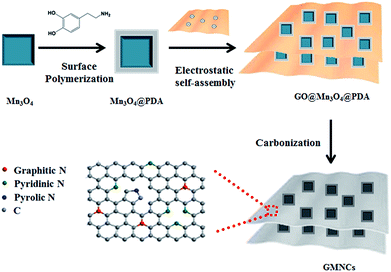 | ||
| Scheme 1 Schematic illustration on the preparation of the GNS@MnO@N-doped carbon composites (GMNCs). | ||
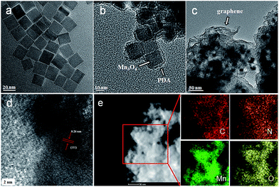
The morphologies of the as-prepared composites were examined using SEM and TEM. As shown in Fig. 1a, the as-prepared Mn3O4 nanocrystals are square prism-shaped, with an average diameter of ∼20 nm. After coating with polydopamine, the Mn3O4 nanocrystals are coated uniformly with a ∼2 nm-thick polymer layer (Fig. 1b and S1, see ESI†). When the graphene oxide (GO) is introduced and then the as-prepared composites are annealed, the Mn3O4@PDA nanocrystals are encapsulated into the graphene, forming the GNS@MnO@N-doped carbon composites. The SEM image reveals an interconnected and porous graphene framework (Fig. S2a, see ESI†). A high-magnification SEM image shows the distinct crumpled structure of graphene and the attached nanocrystals on its surface, suggesting an efficient assembly between the Mn3O4@PDA nanocrystals and graphene (Fig. S2b, see ESI†). The TEM image in Fig. 1c shows that plenty of nanoparticles with a cubic morphology were uniformly encapsulated into the wrinkling graphene. The HRTEM image of the region marked in Fig. 1d shows clear lattice fringes separated by 0.26 nm, which corresponds to the (111) lattice plane of MnO. Furthermore, the uniformly dispersed MnO nanocrystals on the graphene sheets are further elucidated by the scanning TEM (STEM) image and the corresponding element mapping images of C, Mn and O (Fig. 1e). Moreover, the even distribution of the N, derived from the pyrolysis of PDA,40 further confirmed the homogeneous carbon shell cover on the composite.
The crystalline nature of the as-prepared composites is further confirmed using the XRD patterns. As shown in Fig. 2a, all the intense diffraction peaks are well indexed to the hausmannite Mn3O4 (JCPDS 24-0734) phase.15 It is well known that heat treatment can result in the transformation of its crystalline phase because Mn3O4 is not stable in the presence of carbon under high temperature. For instance, annealing Mn3O4@PDA nanocrystals at 800 °C made their crystalline phase change, it is different from the original XRD pattern of Mn3O4 (Fig. S3a, see ESI†). While annealing Mn3O4@PDA nanocrystals at 900 °C can show strong diffraction peaks (Fig. S3b, see ESI†). Interestingly, annealing the GNS@Mn3O4@PDA composites at only 800 °C could show strong diffraction peaks at 35.0°, 40.6°, 58.8°, 70.3°, and 73.8° which are indexed as the (111), (200), (220), (311) and (222) reflections of cubic MnO (JCPDS 75-0626), respectively (Fig. 2b). No other characteristic peaks from the impurities are observed, indicating that the annealed Mn3O4 is completely converted into MnO in the presence of sufficient carbon under relatively low temperatures. Moreover, a broad peak observed at 26.0° is attributed to the (002) plane of the graphite, suggesting the presence of disordered or amorphous carbon. Raman spectroscopy further confirms the existence of MnO and the formation of N-doped carbon (Fig. 2c). The peak at 647 cm−1 is assigned to the Mn–O vibration.28,29 Additionally, the two broad peaks at 1358 and 1597 cm−1 are attributed to the characteristic D-band and G-band vibration modes of carbon, respectively. Obviously, the intensity of the D band is higher than that of the G band, suggesting the existence of defects, disordered and non-graphitic carbon in the sample.27,28 The N-doped carbon was promising for providing more Li storage sites and higher ORR activities than graphitic carbon. TGA is used to determine the chemical composition of the GMNCs (Fig. 2d). The results show that the GMNC composite contains ca. 64.9% MnO, which was measured using TG analysis at air atmosphere on the basis of the complete burning up of the GMNCs and the transformation from MnO to Mn2O3 at 900 °C.20,43
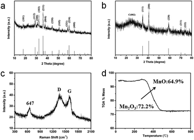 | ||
| Fig. 2 XRD patterns of (a) the Mn3O4 nanocrystals and (b) the GMNCs. (c) Raman spectrum, and (d) TGA curve of the GMNCs. | ||
XPS is performed to further investigate the surface electronic states and the composition of the GMNCs. As shown in Fig. 3a, in the survey spectrum, the detected peaks of Mn2p, O1s, C1s and N1s confirm the presence of Mn, O, C and N elements in the sample. Here, the peaks arising from Mn (2p and 3p) and O (1s) are assigned to MnO. Meanwhile, the peak labeled C1s originates from the graphene nanosheets. In addition, the peak labeled N1s originates from the PDA. The high-resolution Mn2p spectrum (Fig. 3b) shows two obvious signals at 641.8 eV for Mn2p3/2 and 653.8 eV for Mn2p1/2, confirming the characteristics of MnO.26,28 The high-resolution C1s spectrum (Fig. 3c) can be resolved into four peaks at ca. 284.6, 285.6, 286.4, and 288.6 eV, corresponding to the sp3C–sp3C, N–sp2C, C–O–C, and C–O bonds, respectively. Similarly, the high-resolution N1s spectrum (Fig. 3d) can be fitted into three peaks at 400.4 and 398.9 eV with a weak peak at 394.5 eV, corresponding to pyrrolic, pyridinic, and Mn–N bonds, respectively.28,44 These results indicate the successful preparation of GNS@MnO@N-doped carbon composites.
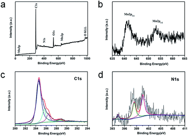 | ||
| Fig. 3 XPS spectra for the GMNCs: (a) the survey spectrum and the high resolution spectra for (b) Mn2p, (c) C1s, (d) N1s. | ||
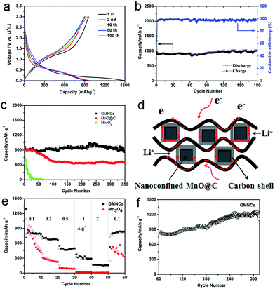
The electrochemical performance of the as-prepared GMNCs as anode materials for LIBs was investigated. The charge–discharge profiles of the different cycles are given in Fig. 4a, which shows the typical characteristics of voltage trends for the MnO electrode, different from that of Mn3O4 (Fig. S4, see ESI†). During the initial discharge process, a long voltage plateau at about 0.30 V is clearly observed which could be ascribed to the reduction of Mn2+ to Mn, whereas for the first charge process, the observed slope between 1.2 and 2.0 V could correspond to the oxidation of Mn to Mn2+. From the second cycle onward, the discharge plateau has shifted to about 0.45 V, which may result from the enhanced kinetics and also indicates the irreversible formation of metal nanoparticles and Li2O.28,45 The results are in good agreement with the CV curves (Fig. S5a, see ESI†). In addition, it can also be seen that the first discharge and charge specific capacities are 1494.4 and 958.7 mA h g−1, respectively, corresponding to an irreversible capacity loss of 35.8%. The large capacity loss is mainly attributed to the irreversible processes such as electrolyte decomposition and inevitable formation of the SEI layer. However, after the first cycle, the coulombic efficiency of the GMNCs increased to 95.5% (Fig. 4b) and then is maintained around 99% for the whole cycling, showing a good reversibility. After 180 cycles, the GMNCs show a high specific reversible capacity of 994.3 mA h g−1, which reveals a good cyclic performance. In order to further study the long-term stability of the GMNCs, a different electrode is examined under the same electrochemical conditions. As shown in Fig. 4c, the GMNCs deliver a higher initial discharge specific capacity of 1024 mA h g−1 and maintain a reversible capacity of 754.3 mA h g−1 after 350 cycles at 0.1 A g−1, corresponding to capacity retentions of 73.7%, which shows a better lithium storage performance than those of the reported MnO-based materials (Table S1, see ESI†). As a comparison, the MnO@C shows a higher initial discharge specific capacity of 1277.4 mA h g−1, however, the capacity drops dramatically during the first 100 cycles and is about 465.8 mA h g−1 after 350 cycles, which corresponds to capacity retentions of 36.5%. In the case of the pure Mn3O4 electrode, it shows a lower initial discharge specific capacity of 663.8 mA h g−1 and a drastic capacity decay. Apparently, this result indicates that the nanoconfinement of the MnO@C particles inside the graphene (double carbon coating design) plays a key role in the significant enhancement of the cycling stability. In addition to the improved cycle stability, the GMNCs also show favorable rate capabilities, which deliver capacities of 873.8, 737.2, 550.1, 374.1, and 165.2 mA h g−1 at current densities of 0.1, 0.2, 0.5, 1, and 2 A g−1, respectively (Fig. 4e). The results are remarkably superior to those of Mn3O4, which shows a continuous capacity decrease at each current density in the range of 0.1–2 A g−1, decaying from 897.9 to 19 mA h g−1. It is obvious that the N-doped double carbon coating plays an important role in increasing the electrical conductivity and reducing the charge-transfer impedance, which can be confirmed using electrochemical impedance spectroscopy (EIS) measurements (Fig. S5b, see ESI†). Remarkably, when the rate of the GMNCs is finally returned to its initial value of 0.1 A g−1 after the back and forth high rate and 50 cycles measurement, the reversible capacity is recovered to 833 mA h g−1 again, which demonstrates that the GMNCs could show the most excellent rate performance. Interestingly, there is a gradual increase in the capacity (more than 1200 mA h g−1) in the following cycles up to 320 cycles (Fig. 4f), which may be ascribed to the progressive formation of a polymeric gel-like film resulting from the kinetically active electrolyte degradation during the conversion process28,46 and the defects formed by the N-doping,47 thus enhancing the lithium storage capacity of the MnO-based composites.
On the basis of the above results, the GMNCs show good electrochemical performances, especially cycling stability, which is attributed to the unique N-doped double carbon coating design. On the one hand, the N-doping could enhance the electrochemical reactivity and electronic conductivity, and generate a large number of defects, which may provide additional Li insertion sites and enhance the lithium storage of the active materials. On the other hand, the nanoconfinement of the optimal core–shell nanostructure combined with the graphene extremely reduces the aggregation of the MnO nanoparticles, and rapidly accommodates the volume variation during the repeated Li+ intercalation/deintercalation processes and ensures the effective diffusion of Li+ and e− into and out of the MnO nanoparticle structure (Fig. 4d).
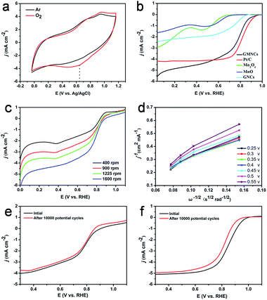
The ORR catalytic activities of the as-prepared GMNCs were then investigated. CV is first performed in Ar- and O2-saturated 0.1 M KOH solution. As shown in Fig. 5a, a featureless voltammetric current is observed for the GMNCs in Ar-saturated solution, whereas a well-defined cathodic peak occurred at about 0.65 V in an O2-saturated solution, confirming the electrocatalytic activity of the GMNCs towards ORR. In addition, the GMNC catalyst shows a more positive ORR peak potential than that of the pure Mn3O4 and MnO catalysts (Fig. S6, see ESI†), highlighting the improved ORR catalytic activity.15 In order to gain further insight into the role of the N-doped double carbon coating in ORR, rotating disk electrode (RDE) experiments are performed in O2-saturated solution and a characteristic set of polarization curves for ORR are displayed in Fig. 5b. It is obvious that the pure Mn3O4, MnO and GNC catalysts exhibit little ORR activity. However, the GMNC catalyst shows a significantly increased ORR onset potential of ca. 0.98 V, which is close to that of the commercial Pt/C (ca. 1.0 V) and much more positive than that of the pure Mn3O4 (ca. 0.70 V), MnO (ca. 0.73 V) and GNC (ca. 0.86 V) catalysts. Furthermore, the GMNC catalyst also shows the more positive half-wave potential and relatively well-defined diffusion-limiting current, which are almost comparable with that of the Pt/C catalyst and much higher than that of the pure Mn3O4, MnO and GNC catalysts (Table S2, see ESI†). The improved ORR catalytic activities could be attributed to the existence of a synergetic effect between the MnO and N-doped double carbon coated structure.
To investigate the kinetics of the oxygen reduction, a set of polarization curves for the GMNC catalyst recorded at different rotation speeds are obtained in Fig. 5c. It is obvious that an increase in the rotation leads to an increase in the current density, which could be attributed to the shortened diffusion distance of oxygen at high speeds.48 According to the polarization curves at the different potentials, the corresponding Koutecky–Levich (K–L) equations are obtained to analyze the kinetic parameters for ORR process (Fig. 5d). The K–L plots at the different electrode potentials exhibit good linearity, which suggests first-order reaction kinetics toward the concentration of dissolved oxygen and a similar electron transfer number for ORR. Based on the slopes of the K–L plots, the electron transfer number (n) of the GMNC catalyst is calculated to be on average 3.5, which suggests that the GMNC catalyst exhibits a combination of four-electron and two-electron reaction pathways, but mainly the former one towards oxygen reduction. In contrast, the electron transfer number of pure Mn3O4, MnO and GNCs catalysts at the same potential is only 3.30, 3.23 and 3.08 (Fig. S7 and Table S2, see ESI†). To verify ORR pathway, a rotating ring-disk electrode (RRDE) experiment for the GMNC catalyst is performed to monitor the formation of the peroxide species (HO2−) during ORR process.13 As shown in Fig. S8 (see ESI†), the electron transfer number is calculated to be on average 3.53, which is well consistent with the results obtained from the K–L plots based on the RDE experiments. Interestingly, these results are almost comparable with that of the reported MnO-based materials.11,22–24,49–53
To confirm the enhanced stability of the GMNC catalyst for ORR, the polarization curves before and after the durability test are investigated. Obviously, the polarization curves with weak degradation in the half-wave potential were observed on the GMNC catalyst after 10![[thin space (1/6-em)]](https://www.rsc.org/images/entities/char_2009.gif) 000 potential cycles (Fig. 5e), whereas there is obvious degradation for the commercial Pt/C catalyst (Fig. 5f). These comparisons clearly demonstrate that the GMNC catalyst is much more stable than Pt/C in an alkaline medium. Most importantly, the GMNC catalyst possesses low cost characteristics, indicating a promising cathode catalyst candidate for alkaline methanol fuel cell applications.
000 potential cycles (Fig. 5e), whereas there is obvious degradation for the commercial Pt/C catalyst (Fig. 5f). These comparisons clearly demonstrate that the GMNC catalyst is much more stable than Pt/C in an alkaline medium. Most importantly, the GMNC catalyst possesses low cost characteristics, indicating a promising cathode catalyst candidate for alkaline methanol fuel cell applications.
Conclusions
In summary, we have developed a facile and effective method to synthesize GMNCs through the impregnation of MnO@N-doped carbon nanoparticles into a conductive graphene matrix. The as-prepared GMNCs present improved Li storage properties and high ORR activities. The double carbon coating design can not only suppress the agglomeration and growth of Mn3O4 nanocrystals during the calcination process, but also permits high electrochemical performance for both LIBs and ORR. On the one hand, the highly conductive double carbon matrix provides a conductive channel to improve the Li ion insertion and charge transfer efficiency and effectively buffers the volume changes of MnO during the electrochemical reaction process. On the other hand, the synergetic effects between the MnO and N-doped double carbon make a remarkable contribution to a high ORR activity. The novel structure described here can be further extended to the preparation of many other kinds of metal/metal oxides-containing double carbons for wide applications including energy storage, catalysis, and electrocatalysis.Acknowledgements
This work was supported by financial aid from the National Natural Science Foundation of China (Grant No. 51502284, 21521092, 51372242, 21401186 and 21210001), the Hong Kong, Macao and Taiwan Science and Technology Cooperation Special Project of Ministry of Science and Technology of China (No. 2014DFT10310), the Program of Science and Technology Development Plan of Jilin Province of China (No. 20140201007GX), the National Key Basic Research Program of China (No. 2014CB643802) and the Jilin Province Youth Foundation (20130522122JH and 20150520007JH).Notes and references
- M. Winter and J. B. Brodd, Chem. Rev., 2004, 104, 4245–4259 CrossRef CAS PubMed.
- J. M. Tarascon and M. Armand, Nature, 2001, 414, 359–367 CrossRef CAS PubMed.
- P. Poizot, S. Laruelle, S. Grugeon, L. Dupont and J. M. Tarascon, Nature, 2000, 407, 496–499 CrossRef CAS PubMed.
- H. Wang, H. B. Feng and J. H. Li, Small, 2014, 10, 2165–2181 CrossRef CAS PubMed.
- L. H. Tang, Y. Wang, Y. M. Li, H. B. Feng, J. Lu and J. H. Li, Adv. Funct. Mater., 2009, 19, 2782–2789 CrossRef CAS.
- L. L. Zhang, M. Wei, S. Q. Wang, Z. Li, L. X. Ding and H. H. Wang, Chem. Sci., 2015, 6, 3211–3216 RSC.
- H. G. Wang, S. Yuan, D. L. Ma, X. B. Zhang and J. M. Yan, Energy Environ. Sci., 2015, 8, 1660–1681 CAS.
- Y. Liang, P. Zhang and J. Chen, Chem. Sci., 2013, 4, 1330–1337 RSC.
- W. Wei, S. B. Yang, H. X. Zhou, I. Lieberwirth, X. L. Feng and K. Müllen, Adv. Mater., 2013, 25, 2909–2914 CrossRef CAS PubMed.
- E. Kang, Y. S. Jung, A. S. Cavanagh, G. H. Kim, S. M. George, A. C. Dillon, J. K. Kim and J. Lee, Adv. Funct. Mater., 2011, 21, 2430–2438 CrossRef CAS.
- Y. Z. Dong, M. J. Liu, Y. Liu, S. W. Wang and J. H. Li, J. Mater. Chem. A, 2015, 3, 19969–19973 CAS.
- Y. Zheng, Y. Jiao, L. Ge, M. Jaroniec and S. Z. Qiao, Angew. Chem., Int. Ed., 2013, 52, 3110–3116 CrossRef CAS PubMed.
- H. X. Zhong, J. Wang, Y. W. Zhang, W. L. Xu, W. Xing, D. Xu, Y. F. Zhang and X. B. Zhang, Angew. Chem., Int. Ed., 2014, 53, 14235–14239 CrossRef CAS PubMed.
- M. Sun, Y. Liu, H. J. Liu, J. H. Qu and J. H. Li, Nanoscale, 2015, 7, 1250–1269 RSC.
- Y. M. Tan, C. F. Xu, G. X. Chen, X. L. Fang, N. F. Zheng and Q. J. Xie, Adv. Funct. Mater., 2012, 22, 4584–4591 CrossRef CAS.
- G. Q. Zhang, B. Y. Xia, C. Xiao, L. Yu, X. Wang, Y. Xie and X. W. Lou, Angew. Chem., Int. Ed., 2013, 52, 8643–8647 CrossRef CAS PubMed.
- Z. L. Wang, D. Xu, H. X. Zhong, J. Wang, F. L. Meng and X. B. Zhang, Sci. Adv., 2015, 1, e1400035 Search PubMed.
- F. Y. Cheng, J. Shen, B. Peng, Y. D. Pan, Z. L. Tao and J. Chen, Nat. Chem., 2011, 3, 79–84 CrossRef CAS PubMed.
- X. Zhang, Z. Xing, L. L. Wang, Y. C. Zhu, Q. W. Li, J. W. Liang, Y. Yu, T. Huang, K. B. Tang, Y. T. Qian and X. Y. Shen, J. Mater. Chem., 2012, 22, 17864–17869 RSC.
- S. Zhang, L. Zhu, H. Song, X. Chen and J. Zhou, Nano Energy, 2014, 10, 172–180 CrossRef CAS.
- K. Zhang, X. Han, Z. Hu, X. Zhang, Z. Tao and J. Chen, Chem. Soc. Rev., 2015, 44, 699–728 RSC.
- J.-S. Lee, G. S. Park, H. I. Lee, S. T. Kim, R. Cao, M. Liu and J. Cho, Nano Lett., 2011, 11, 5362–5366 CrossRef CAS PubMed.
- W. Xiao, D. Wang and X. W. Lou, J. Phys. Chem. C, 2010, 114, 1694–1700 CAS.
- F. Cheng, Y. Su, J. Liang, Z. Tao and J. Chen, Chem. Mater., 2010, 22, 898–905 CrossRef CAS.
- Y. L. Cao, H. X. Yang, X. P. Ai and L. F. Xiao, J. Electroanal. Chem., 2003, 557, 127–134 CrossRef CAS.
- Y. M. Sun, X. L. Hu, W. Luo, F. F. Xia and Y. H. Huang, Adv. Funct. Mater., 2013, 23, 2436–2444 CrossRef CAS.
- K. J. Zhang, P. X. Han, L. Gu, L. X. Zhang, Z. H. Liu, Q. S. Kong, C. J. Zhang, S. M. Dong, Z. Y. Zhang, J. H. Yao, H. X. Xu, G. L. Cui and L. Q. Chen, ACS Appl. Mater. Interfaces, 2012, 4, 658–664 CAS.
- Y. Xiao, X. Wang, W. Wang, D. Zhao and M. H. Cao, ACS Appl. Mater. Interfaces, 2014, 6, 2051–2058 CAS.
- W. Luo, X. L. Hu, Y. M. Sun and Y. H. Huang, ACS Appl. Mater. Interfaces, 2013, 5, 1997–2003 CAS.
- Y. Xia, Z. Xiao, X. Dou, H. Huang, X. H. Lu, R. J. Yan, Y. P. Gan, W. J. Zhu, J. P. Tu, W. K. Zhang and X. Y. Tao, ACS Nano, 2013, 7, 7083–7092 CrossRef CAS PubMed.
- D. Chen, H. B. Feng and J. H. Li, Chem. Rev., 2012, 112, 6027–6053 CrossRef CAS PubMed.
- Y. Su, S. Li, D. Wu, F. Zhang, H. Liang, P. Gao, C. Cheng and X. Feng, ACS Nano, 2012, 6, 8349–8356 CrossRef CAS PubMed.
- C. Zhang, X. Peng, Z. Guo, C. Cai, Z. Chen, D. Wexler, S. Li and H. Liu, Carbon, 2012, 50, 1897–1903 CrossRef CAS.
- X. Jiang, X. Yang, Y. Zhu, Y. Yao, P. Zhao and C. Li, J. Mater. Chem. A, 2015, 3, 2361–2369 CAS.
- Z. Zhang, L. Zhang, W. Li, A. Yu and P. Wu, ACS Appl. Mater. Interfaces, 2015, 7, 10395–10400 CAS.
- D. H. Liu, H. Y. Lü, X. L. Wu, B. H. Hou, F. Wan, S. D. Bao, Q. Yan, H. M. Xie and R. S. Wang, J. Mater. Chem. A, 2015, 3, 19738–19746 CAS.
- U. N. Maiti, W. J. Lee, J. M. Lee, Y. Oh, J. Y. Kim, J. E. Kim, J. Shim, T. H. Han and S. O. Kim, Adv. Mater., 2014, 26, 40–67 CrossRef CAS PubMed.
- Y. Liu, P. Liu, D. Wu, Y. Huang, Y. Tang, Y. Su, F. Zhang and X. Feng, Chem.–Eur. J., 2015, 21, 5617–5622 CrossRef CAS PubMed.
- H. G. Wang, Y. Wang, Y. Li, Y. Wan and Q. Duan, Carbon, 2015, 82, 116–123 CrossRef CAS.
- R. Liu, S. M. Mahurin, C. Li, R. R. Unocic, J. C. Idrobo, H. J. Gao, S. J. Pennycook and S. Dai, Angew. Chem., Int. Ed., 2011, 50, 6799–6802 CrossRef CAS PubMed.
- M. H. Oh, T. Yu, S. H. Yu, B. Lim, K. T. Ko, M. G. Willinger, D. H. Seo, B. H. Kim, M. G. Cho, J. H. Park, K. Kang, Y. E. Sung, N. Pinna and T. Hyeon, Science, 2013, 340, 964–968 CrossRef CAS PubMed.
- W. S. Hummers and R. E. Offeman, J. Am. Chem. Soc., 1958, 80, 1339 CrossRef CAS.
- R. Ma, Y. Bando, L. Zhang and T. Sasaki, Adv. Mater., 2004, 16, 918–922 CrossRef CAS.
- W. Jiao, N. Li, L. Z. Wang, L. Wen, F. Li, G. Liu and H. M. Cheng, Chem. Commun., 2013, 49, 3461–3463 RSC.
- B. Sun, Z. Chen, H. S. Kim, H. Ahn and G. Wang, J. Power Sources, 2011, 196, 3346–3349 CrossRef CAS.
- Y. Xiao and M. H. Cao, ACS Appl. Mater. Interfaces, 2015, 7, 12840–12849 CAS.
- Y. Mao, H. Duan, B. Xu, L. Zhang, Y. S. Hu, C. C. Zhao, Z. X. Wang, L. Q. Chen and Y. S. Yang, Energy Environ. Sci., 2012, 5, 7950–7955 CAS.
- N. Mahmood, C. Z. Zhang, J. Jiang, F. Liu and Y. L. Hou, Chem.–Eur. J., 2013, 19, 5183–5190 CrossRef CAS PubMed.
- Y. T. Meng, W. Q. Song, H. Huang, Z. Ren, S. Y. Chen and S. L. Suib, J. Am. Chem. Soc., 2014, 136, 11452–11464 CrossRef CAS PubMed.
- K. X. Lei, X. P. Han, Y. X. Hu, X. Liu, L. Cong, F. Y. Cheng and J. Chen, Chem. Commun., 2015, 51, 11599–11602 RSC.
- C. H. Kuo, I. M. Mosa, S. Thanneeru, V. Sharma, L. Zhang, S. Biswas, M. Aindow, S. P. Alpay, J. F. Rusling, S. L. Suib and J. He, Chem. Commun., 2015, 51, 5951–5954 RSC.
- R. W. Chen, J. Yan, Y. Liu and J. H. Li, J. Phys. Chem. C, 2015, 119, 8032–8037 CAS.
- Y. Gorlin and T. F. Jaramillo, J. Am. Chem. Soc., 2010, 132, 13612–13614 CrossRef CAS PubMed.
Footnote |
| † Electronic supplementary information (ESI) available: Additional chemicals and materials, electrocatalysis measurements in detail, XRD, and electrochemical characterizations. See DOI: 10.1039/c5sc04668h |
| This journal is © The Royal Society of Chemistry 2016 |

