Catalytic CO2 hydrogenation to formic acid over carbon nanotube-graphene supported PdNi alloy catalysts†
Lan Thi Mai Nguyen‡
a,
Hunmin Park‡a,
Marimuthu Banub,
Jae Yul Kimc,
Duck Hyun Younb,
Ganesan Mageshb,
Won Yong Kima and
Jae Sung Lee*b
aDepartment of Chemical Engineering, Pohang University of Science and Technology (POSTECH), Pohang, 790-784, Korea
bSchool of Energy and Chemical Engineering, Ulsan National Institute of Science and Technology (UNIST), Ulsan, 689-798, Korea. E-mail: jlee1234@unist.ac.kr
cBasic Materials & Chemicals R&D, LG Chem, Ltd., Daejeon, 305-738, Korea
First published on 3rd December 2015
Abstract
Pure formic acid was successfully produced via CO2 hydrogenation for the first time over a heterogeneous catalyst of PdNi alloy on a carbon nanotube-graphene (CNT-GR) support in water as an eco-friendly solvent without a base additive. The highest formic acid yield obtained was 1.92 mmol with a turnover number of 6.4 and a turnover frequency of 1.2 × 10⁻⁴ s−1 under mild reaction conditions of 40 °C and 50 bar. Alloying Pd with Ni brought a significant enhancement in catalytic activity compared to the monometallic Pd catalyst. In addition, the CNT-GR composite as a catalytic support improved the dispersion of Pd–Ni alloy particles, which exhibited good stability under the reaction conditions.
1. Introduction
Formic acid (FA) is an organic chemical with a good environmental compatibility and has been used for a variety of applications such as pharmaceutical, agriculture or textile industries. Currently, industrial FA production is mainly based on the carbonylation of methanol followed by hydrolysis.1 Recently, direct CO2 hydrogenation to FA has received great attention as a potential route for reutilization CO2 as an abundant and sustainable carbon feedstock.2–5 Over the last decade, the combination of CO2 fixation and H2 storage in one compound like FA has become an interesting and challenging research topic worldwide.6–8| CO2 + H2 = HCOOHΔG0298 K = +32.9 kJ mol−1 | (1) |
Since the thermodynamics of the pure FA formation from CO2 hydrogenation is not favorable even at high temperature and pressure,3,9 organic and inorganic bases are often added to the reaction mixture to increase the conversions, although the pure formic acid has to be recovered from the formed formate salts in an additional post-treatment step.9
To date, catalytic CO2 hydrogenation to formate or FA has focused on homogeneous catalysts (e.g., Ru, Rh, Ir, Fe, Pd, etc.), which offered high activity and selectivity with or without base additives to stabilize the product formic acid derivatives.2,4,10–12 Notably, Moret and co-workers reported Ru complex as a highly active catalyst for CO2 hydrogenation to produce pure FA in the mixture of (DMSO/H2O) solvent with FA concentration up to 1.31 M.2 However, FA yield was very low with a turnover-number (TON) of 0.95 and a turnover-frequency (TOF) of 7.9 × 10⁻³ h−1. Also homogeneous catalyst systems have a number of intrinsic drawbacks including difficulty in isolation and purification of the product from the reaction solution. In order to address the issue, heterogeneous catalysts (e.g., Ni, Pd, Au) for the FA synthesis from CO2 hydrogenation have been investigated in both theoretical13–15 and experimental studies.3,16–19 Heterogeneous catalysts are easily recovered after reaction and readily applicable to a continuous reaction system in a large industrial process. However, because of their low activity and chemo-selectivity,8 heterogeneous catalysts were studied under the presence of bases (e.g., amine, NaOH, NaHCO3) and/or specific solvents. To the best of our knowledge, pure FA production over heterogeneous catalysts has not been reported and the high yield synthesis of pure FA over a more practical heterogeneous catalyst is in great demand.
In the present work, we attempt to develop a heterogeneous catalyst for the direct hydrogenation of CO2 to pure FA. The active component was a PdNi alloy, which exhibited a significantly enhanced catalytic activity compared to monometallic Pd catalyst. As a support, carbon nanotube-graphene (CNT-GR) composite was employed. CNT and GR have high surface area, good dispersion of catalytic particles and inertness with active components.20,21 However, GR sheets stack spontaneously over themselves and CNTs easily bundle together, and hence the majority of their surfaces cannot be used effectively for catalyst preparation. When CNT-GR composite is formed, they serve as a spacer for each other and the stacking of GR and the bundling of CNTs are prevented to expose their own high surface areas.22,23 Thus the heterogeneous PdNi alloy catalyst supported on CNT-GR produced pure FA under mild conditions without further product purification step and was easily separated from product by simple filtration. Its catalytic activity and selectivity was comparable with known homogeneous catalysts. A reaction mechanism for pure FA synthesis over heterogeneous catalyst also has been proposed.
2. Experimental section
2.1 Materials and catalyst synthesis
Palladium(II) nitrate hydrate (Pd(NO3)2, 99.999%), nickel(II) nitrate hexahydrate (Ni(NO3)2·6H2O, 99.999%), hydrazine monohydrate (N2H4·H2O, 64–65%), sodium nitrate (NaNO3), potassium permanganate (KMnO4) and concentrated sulfuric acid (H2SO4, 98%) were purchased from Sigma Aldrich. Graphite flake (325 mesh) was provided by Alpha Aesar and extra pure H2O2 by Junsei (Japan). Carbon nanotube (CNT, CM-95) was purchased from Hanwha Chemical (Korea). Carbon dioxide (99.999%) and hydrogen (99.999%) were provided by Daesung Gases Supplier (Korea). Deionized (DI) water was purged with argon for 2 h prior to use. All chemicals were used without further purification.Graphene oxide (GO) was synthesized by Hummers method using graphite flake (ESI S1†). In this study, Ni, Pd and PdNi supported on CNT/GR composite were obtained by wet impregnation followed by reduction. 0.25 g each of CNT and GO were first dispersed in 220 ml water in a 500 ml round flask, and then ultrasonicated for 3 h. Then the mixture of Pd(NO3)2 and Ni(NO3)2 with total 1 mmol of metals (Pd/Ni atomic ratio of 3/7) was added drop-wise to CNT-GO colloidal solution followed by stirring for 2 h. In addition, once the solution temperature reached 90 °C, 10 ml of hydrazine hydrate (65% in water) was added with vigorous stirring to obtain immediately a black solution. After 12 h, the solution was cooled down to room temperature. The black solution was then filtered and washed with water and acetone several times, and finally dried in vacuum at 110 °C for 12 h.
2.2 Catalyst characterization
Powder X-ray diffraction (XRD) patterns were obtained using a PW 3040/60 X'pert Pro (PANalytical) with Cu Kα radiation. The HRTEM images were recorded on a JEOL TEM-2100F/CESCOR microscope operated at 200 kV. Elemental analyses (EA) were performed using Elemental Determinators (Thermo Scientific, ELAN DRC-II). The compositional analysis of metals and alloy was done by Inductively Coupled Plasma-Optical Emission Spectrometers (ICP/OES, Varian 720-ES). The surface composition and chemical state of catalyst surface were obtained from the X-ray photoelectron spectrometer (XPS, Thermo Fischer, Kα). In addition, Fourier transform infrared spectroscopy (FT-IR, Agilent, 670-IR) was used to identify the presence of functional groups on surface of catalysts with the scanning range from 500 to 4000 cm−1. Nitrogen adsorption measurements at 77 K were performed on Nanoporosity-XQ (Mirae Scientific Instruments, Korea) to determine the specific surface area and pore size distribution.2.3 Hydrogenation of CO2
Hydrogenation of CO2 to formic acid was carried out in a high-pressure stainless steel autoclave (300 ml, internal diameter 64 mm) with a magnetic stirrer. In a typical run, 0.5 g of the catalyst was charged into a batch reactor with 90 ml DI water as solvent. The reactor was purged several times with N2 and H2, and pressurized with H2, CO2 (H2/CO2 = 1) up to desirable pressure. CO2 was heated at 70 °C prior to injection to prevent liquefaction at high pressure. After that, the system was heated by a mantle equipped with a temperature controller, followed by stirring at 170 rpm. The reaction was carried out for 15 h. At the end of the reaction, the reactor was cooled down to room temperature naturally, and then pressure was released to ambient condition. For the recycling test, the catalyst was recovered by evaporating liquid products in vacuum oven and treated with H2 at 130 °C for 1 h to remove hydrocarbon residues before each cycle of catalytic reactions.The liquid product in the autoclave obtained after filtration was analysed by Agilent 1200 series HPLC system equipped with a quaternary pump, a thermo-prep auto sampler, an online degasser, and a thermostatically controlled column compartment. The Hi-plex H column (7.7 × 300 mm) was used at 55 °C using 5 mM H2SO4 solution as an eluent. The flow rate was kept at 0.6 ml min−1 with a run time of 30 min and the UV detector of 210 nm. The sample liquid injection volume was 20 μl. A series of standard solutions of formic acid was prepared (0.005 M, 0.01 M, 0.015 M, 0.02 and 0.03 M, respectively) to generate a calibration curve with a R2 of 0.999. The gaseous samples were analysed using an Agilent HP 6890 GC with a Carboxen 1000 column and a thermal conductivity detector. The gas products collected at reactor outlet were only CO2, H2 and N2 with no other gas products.
3. Results and discussion
3.1 Characterization of physical properties
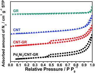
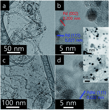
In screening experiments described in Section 3.2, Pd3Ni7 was found to be the optimum composition of the alloy catalyst. The nitrogen sorption isotherms of CNT-GR and PdNi/CNT-GR are shown in Fig. 1. As expected, combination of CNT and GR as a composite created mesopores, which were absent in CNT or GR alone. These mesopores hence come from the role as spacers of two types of nano carbons for each other preventing CNT bundling or GR sheets stacking.24 As a result, CNT-GR offers high surface area and large pore volume that are essential to disperse metal nanoparticles on the surface of the support.23,24 The surface areas of the CNT-GR and Pd3Ni7/CNT-GR were 288 and 266 m2 g−1, respectively, which were much higher than those of CNT (224 m2 g−1) or GR (33.0 m2 g−1). Moreover, the external surface area of CNT-GR (231 m2 g−1) remarkably increased compared to that of CNT (160 m2 g−1) by adding GR while the micropore volume slightly decreased (56.9 m2 g−1 and 62.4 m2 g−1 for CNT-GR and CNT, respectively). These changes in textural properties are consistent with the ‘mutual spacer mechanism’ for the formation of CNT-GR composite stated above. The textural properties are summarized in Table S1.†The particle size and compositions of Pd and Pd3Ni7 on CNT-GR composite could be determined by TEM in Fig. 2. The Pd and PdNi nanoparticles are uniform and well-dispersed on the surface of CNT-GR support with small particle sizes of 3 nm and 4 nm, respectively. In order to identify the possible formation of Pd–Ni alloy particles, the HRTEM images were recorded. The lattice distances of 2.27 Å and 2.00 Å observed in Fig. 2b are in good agreement with 2.244 Å and 1.944 Å for (111) and (002) lattice planes of Pd, respectively (76148 ICSD card).25 The Pd–Ni phase in Fig. 2d shows a slight shrinkage in the lattice distance of PdNi(111) to 2.22 Å. The energy dispersive spectrum (EDS) analysis of Pd3Ni7/CNT-GR in Fig. S2† confirms the presence of carbon, oxygen, nickel, palladium elements on the alloy catalyst.
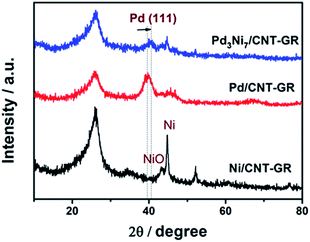
In XRD patterns of Fig. 3, the peak located at a 2θ value of about 26° is attributed to the graphite (002) plate of the GR-CNT support. The characteristic peaks of Pd/CNT-GR (39.9°, 46.1°, 67.8°) and Ni/CNT-GR (44.7°, 52.1°, 76.7°) reflect Pd (Fm3m, JCPDS # 01-087-0645) and Ni (Fm3m, JCPDS # 01-071-3740) metallic phases, respectively. However, the XRD peaks of the metals in Pd3Ni7/CNT-GR are significantly weaker than those in monometallic catalysts, indicating that Ni addition lowers crystallinity in agreement with previous reports.26–28 The Pd (111) peak of Pd3Ni7/CNT-GR catalyst slightly shifts to a higher 2θ angle compared to the corresponding Pd (111) peak in the Pd/CNT-GR, revealing the shrinkage of the lattice distance by the formation of PdNi alloy. The new distance from the XRD (2.23 Å) is consistent with the distance observed by TEM (2.22 Å). From the broadening of XRD peaks, the crystallite sizes of Pd and PdNi alloy in Pd/CNT-GR and Pd3Ni7/CNT-GR catalysts were around 2.9 nm and 5.2 nm, respectively. Unalloyed Ni particles are also present in Pd3Ni7/CNT-GR catalyst as evidenced by sharp peaks at 44.7° and 52.1°. But the quantity of this residual Ni species which do not attend PdNi alloy formation is not significant. Hence, both TEM and XRD have demonstrated PdNi alloy formation in Pd3Ni7/CNT-GR catalyst.
The efficient reduction of graphene oxide (GO) by hydrazine is confirmed by the FTIR spectra for Pd3Ni7/CNT-GR in Fig. S3.† Characteristic peaks of GO at O![[double bond, length as m-dash]](https://www.rsc.org/images/entities/char_e001.gif) C–OH (1000 cm−1), O–C–O (1100–1250 cm−1), C
C–OH (1000 cm−1), O–C–O (1100–1250 cm−1), C![[double bond, length as m-dash]](https://www.rsc.org/images/entities/char_e001.gif) O (1600 cm−1), and O
O (1600 cm−1), and O![[double bond, length as m-dash]](https://www.rsc.org/images/entities/char_e001.gif) C–OH (1750 cm−1)29 bonds disappeared after hydrazine treatment. Also, the ID/IG ratio of GO (0.98) in Raman spectra increased to 1.2, due to the presence of unrepaired defects that remained after the removal of large amounts of oxygen-containing functional groups. This clearly indicates the successful reduction of GO. The metal contents in the catalyst were determined by the ICP/AES analysis as 5.14 and 6.76 wt% for Pd and Ni, respectively. Thus the Pd/(Pd + Ni) atomic ratio from ICP analysis (29.5 at%) is in good agreement with the expected value (30 at%).
C–OH (1750 cm−1)29 bonds disappeared after hydrazine treatment. Also, the ID/IG ratio of GO (0.98) in Raman spectra increased to 1.2, due to the presence of unrepaired defects that remained after the removal of large amounts of oxygen-containing functional groups. This clearly indicates the successful reduction of GO. The metal contents in the catalyst were determined by the ICP/AES analysis as 5.14 and 6.76 wt% for Pd and Ni, respectively. Thus the Pd/(Pd + Ni) atomic ratio from ICP analysis (29.5 at%) is in good agreement with the expected value (30 at%).
The XPS spectrum of Pd3Ni7/CNT-GR shown in Fig. 4 reveals surface oxidation state and their relative concentration of Pd- and Ni-species. Pd 3d5/2 and 3d3/2 XPS peaks in Pd3Ni7/CNT-GR appear at 335.6 eV and 341.0 eV, which indicates mixed valences of Pd-species on the catalyst surface; Pd0, Pd2+ (PdO) and Pd4+ (PdO2).30 The relative atomic percent of Pd0-species in the total amount of loaded Pd is 62.6% in Pd3Ni7/CNT-GR and 52.5% in Pd/CNT-GR (Table 1). The surface exposed Pd concentration of Pd3Ni7/CNT-GR (5.197 at%) determined by XPS (Fig. S5†) is considerably higher than the intended value (0.72 at%), which indicates that Pd is well dispersed on the surface while carbon supports are slightly stacked and aggregated. The surface concentration of Ni determined by XPS is 10.9 at%, which corresponds to a Pd/(Pd + Ni) ratio of 32.3 at%. This is close to the intended value (30 at%) and measured ICP/AES value (29.4 at%), indicating that Pd and Ni atoms form randomly mixed alloy particles instead of a core–shell structure. Even though their bulk crystallinity is observed as reduced Pd in XRD analysis, the surface Pd species contains oxidized species because of exposure to atmosphere. However, these oxidized Pd species on the surface would be easily reduced by hydrogen during the CO2 hydrogenation reaction.
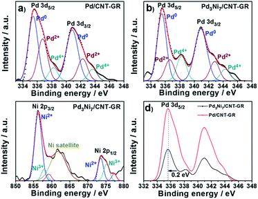 | ||
| Fig. 4 Pd 3d and Ni 2p XPS spectra; (a) Pd in Pd/CNT-GR, (b) Pd in Pd3Ni7/CNT-GR, (c) Ni in Pd3Ni7/CNT-GR, and (d) comparison of Pd spectra in Pd/CNT-GR and Pd3Ni7/CNT-GR. | ||
| Sample | Eb, Pd 3d5/2 [eV] | Relative content [mol%] | ||||
|---|---|---|---|---|---|---|
| Pd0 | Pd2+ | Pd4+ | Pd0 | Pd2+ | Pd4+ | |
| Pd/CNT-GR | 355.6 | 336.7 | 338.2 | 52.5 | 36.8 | 10.7 |
| Pd3Ni7/CNT-GR | 355.5 | 336.6 | 338.2 | 62.6 | 26.5 | 10.9 |
Furthermore, there is a peak shift (0.2 eV) of Pd 3d5/2 binding energy in Pd3Ni7/CNT-GR to the lower value compared to Pd/CNT-GR, indicating a slight electron donation from Ni to Pd or electronic structure modification of Pd active sites by addition of Ni. The decreased binding energy of Pd 3d might prevent the strong poisoning of Pd surface by reaction intermediate such as CO or carbonate.27 On the other hand, Ni 2p binding energy of Pd3Ni7/CNT-GR (856.4 eV) is shifted to higher value (0.6 eV) compared to Ni/CNT-GR (Fig. S4†), which is consistent with the electron transfer from Ni to Pd in Pd3Ni7/CNT-GR as stated in Pd 3d XPS spectra. The spectrum presented in Fig. 4c shows mainly the features inherent to spectra of NiO mixed with NiOOH of Ni-species31 instead of Ni0-species, which is attributed to surface oxidation by air exposure as observed in Pd 3d spectra. The bulk property of Ni, however, is revealed as reduced metal state by XRD analysis, and the surface oxidized Ni would be easily reduced under reductive atmosphere during the catalytic reaction.
3.2 Catalytic CO2 hydrogenation to HCOOH
As mentioned, catalytic CO2 hydrogenation to HCOOH over heterogeneous catalysts suffers a lot of problems including low activity and selectivity, and unfavorable thermodynamics requiring a base additive. It has not been possible to obtain pure HCOOH through the processes with high yields. Palladium has been known as an active metal for H2 activation as well as CO2 hydrogenation.5,18,32 However, pure Pd can be easily poisoned by some intermediates of the reaction like CO.6,33 Kwak et al. reported that pure Pd was almost inactive for CO2 reduction when it was loaded on inert CNT support.34 Addition of a second component (e.g. La2O3) as an activation site of CO2 underlined the multifunctionality by the formation of atomically dispersed Pd–La bimetallic species in an active catalyst for the reduction of CO2.34In the present work, we attempted to design Pd–Ni alloy metal catalyst, because Ni was found to be a good catalyst for CO2 hydrogenation to HCOOH by theoretical studies.13,14 As references, mono-metallic Ni/CNT-GR and Pd/CNT-GR catalysts were also studied for the same reaction. A blank test without any catalyst did not produce formic acid. The reactions produced exclusively HCOOH (>99% selectivity) with only a trace of acetic acid (Fig. S8†). Hence, HCOOH is considered as the sole product in the following discussion. Fig. 5a reveals that the Pd–Ni bimetallic catalyst has synergistic effect on HCOOH yield compared to mono-metallic Pd/CNT-GR and Ni/CNT-GR catalysts. Indeed, Pd3Ni7/CNT-GR exhibits a significant enhancement in catalytic activity, which is correlated with the lower binding energy of Pd active sites by the addition of Ni (discussed in XPS analysis). This would decrease binding energy between formate intermediate and Pd nanoparticles on the surface of catalyst leading to the enhanced catalytic reaction rates. Furthermore, the high concentration of the surface Pd0-species in the form of PdNi alloys is proposed to contribute to improved HCOOH formation. For Ni/CNT-GR catalyst, the reaction did not occur at all. In addition to its intrinsically low activity, the formation of large Ni metal particles (21 nm, calculated by Scherrer's equation at 44.7° peak in XRD pattern) with protective NiO species (Fig. 3) on the surface may be responsible.
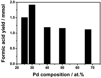 | ||
| Fig. 5 Formic acid yields as a function of Pd content. Reaction conditions: 1 mmol (Pd + Ni) catalysts, 90 ml H2O, P = 50 bar (H2/CO2 = 1), 40 °C, 15 h. | ||
The Pd/Ni atomic ratio was optimized in the hydrogenation of sodium bicarbonate in a previous report.26 Here, in the CO2 hydrogenation to pure FA, we re-optimized the bimetallic composition of Pd/Ni by varying Pd molar content. The result in Fig. 5 shows that the catalyst with Pd/Ni molar ratio of 3/7 has the highest catalytic activity. Over the Pd3Ni7/CNT-GR catalyst, the observed formic acid yield reaches 1.92 mmol, which is significantly higher than the other four catalysts with higher or lower Pd content. As determined by XPS, the exposed amount of Pd species on the catalytic surface exhibits linear relation (R2 ∼ 1) with the nominal amount of Pd in the catalysts (Fig. S5†). However, the higher surface Pd content in bimetallic catalysts above the optimum value does not increase catalytic activity (Fig. 5 and S6†) even though Pd active sites play the main role in H2 activation as well as CO2 hydrogenation. The Pd/(Pd + Ni) ratio determined by XPS (32.3 at%) also indicates that PdNi alloy particles in the catalyst do not form core–shell structure. With the optimized Pd3Ni7, Pd would have an optimal binding energy with the reaction intermediates that gives the highest catalytic reaction rate of CO2 hydrogenation to HCOOH. More details on optimal Pd composition on the catalytic performance will be discussed in the following section (Scheme 1).
The effects of reaction temperature and pressure were investigated in the presence of 1 mmol Pd3Ni7/CNT-GR. As shown in Fig. 6a, the optimal operating temperature was 40 °C at 40 bar of H2 pressure, which produced the highest formic acid yield of 1.35 mmol. Generally, increasing temperature accelerates reaction rate, however, the hydrogenation of CO2 into formic acid is an exothermic reaction (ΔH0298 K = −31.2 kJ mol−1, ΔS0298 K = −0.215 kJ K−1 mol−1), which has unfavorable equilibrium at high temperature (ΔG303 K = 33.95 kJ mol−1 and ΔG323 K = 38.25 kJ mol−1). In addition, the reaction between CO2 and H2 at high temperature normally results in either the formation of CO and H2O (reverse water gas shift reaction) or formic acid decomposition back to CO2 (CO) and H2. On the other hand, the reaction kinetics is not favorable at very low temperature (30 °C) to overcome the activation barrier of the reaction.
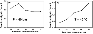 | ||
| Fig. 6 Formic acid yields as functions of (a) reaction temperature and (b) reaction pressure. Reaction conditions: 1 mmol Pd3Ni7/CNT-GR, 90 ml H2O, H2/CO2 = 1, 15 h. | ||
The unfavorable reaction equilibrium of HCOOH formation from CO2 and H2 could be shifted to the product side by increasing total gas pressure. As expected in Fig. 6b, the yield of FA at 40 °C gradually increases with increasing pressures, reaching the highest value at 1.92 mmol at 50 bar. This result is in agreement with the thermodynamics viewpoint as well as previous reports that higher total gaseous pressure is favorable for CO2 reduction into formic acid.2 In summary, the total gas pressure is beneficial to high FA yield while the temperature has a detrimental influence in our limited range of investigation (pressure ≤ 50 bar and temperature ≤ 100 °C). The behavior is understandable on thermodynamics as well as kinetics ground.
In the hydrogenation of CO2 into HCOOH in pure water solvent over a heterogeneous catalyst, some active metal component sites could migrate from the support into the reaction solution, and those leached species could contribute significantly to the catalytic activity. Thus, a leaching test was conducted at 40 °C in 90 ml H2O at 50 bar. The resulting solution after reaction was subsequently filtered, and then the filtrate was used as the catalytic solution for fresh reagents of CO2 and H2 without added catalyst. No additional HCOOH was observed, indicating negligible leaching of the active catalyst. In another test of metal leaching, ICP-OES analysis indicated that there was no Pd but a small Ni content around 0.18 mM l−1 (≤3% of the loaded Ni) in the filtrate after the hydrogenation reaction. This result is acceptable because Ni/NiO is slightly unstable in weakly acidic formic acid solution. The catalytic activity decreases significantly after the first cycle (Fig. S7†), which could be attributed to a small amount of leached Ni from the catalysts. However, the performance is stabilized from the second cycle with negligible deactivation up to 7 cycles. In summary, the CNT-GR supported PdNi alloy catalyst exhibited high efficiency and excellent stability in CO2 hydrogenation into formic acid in addition to its intrinsic practical advantage in separation and recycling.
3.3 A proposed reaction pathway
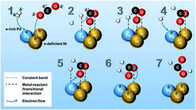
The reaction mechanism of CO2 hydrogenation to methanol or methane over heterogeneous catalysts has been discussed both in theoretical and experimental studies.5 The multifunctionality of the catalytic system plays an important role in CO2 and H2 activation, in which noble metals (Pt, Ru, Rh, and Pd, etc.) are active for splitting H2 into H atoms,35 while transition metal (i.e. Ni)13,14 has high reactivity in the CO2 reduction.34Although there are different proposals in the reaction mechanism on hydrogenation of CO2 into several products (e.g., CH4, CH3OH, CO, methyl formate, etc.),5,34 only a few reaction mechanisms for the hydrogenation of CO2 towards pure formic acid over heterogeneous catalyst has been reported by the theoretical calculation. Peng et al.14,36 verified through density functional theory calculation that CO2 is adsorbed as formate intermediate on Ni surface and consecutively reacts with subsurface H in Ni producing formic acid as final product. In Scheme 1, a possible reaction pathway for HCOOH synthesis on Pd3Ni7 bimetallic catalyst surface is presented. The mechanistic ideas are illustrated in Scheme 1 according to the following steps: (1) as investigated in XPS analysis, there is electron transfer from Ni to Pd atoms. Therefore, Pd and Ni are in the electron-rich and -deficient state, respectively. (2) H2 molecules dissociatively adsorb on Pd surface and the O atoms of CO2 molecule adsorb on the different Ni atoms separately, which is the stabilized form of CO2 on the Ni surface as calculated by previous studies.14,36 (3) The adsorbed H atom on the Pd moves to C atom of adsorbed CO2, and (4) another H atom adsorbs on vacant Pd site. (5) Newly adsorbed H atom on Pd surface forms a new interaction with O atom of adsorbed CO2 on Ni surface, and (6) results in adsorbed HCOOH on Ni surface. (7) Finally, the adsorbed HCOOH on Ni surface leaves the catalytic surface of Pd3Ni7/CNT-GR. The mechanism proposed here addresses a significant role of Pd3Ni7 bimetallic system on the selective formation of formic acid from CO2 hydrogenation. Moreover, the Ni/Pd atomic ratio of PdNi bimetallic system of Scheme 1 (Ni/Pd = 2) is close to the optimized composition of Pd (Ni/Pd = 2.33 for Pd3Ni7), which could explain why Pd3Ni7 composition exhibits the outstanding performance in Fig. 5.
4. Conclusion
In conclusion, we have established a new bimetallic Pd–Ni system supported on CNT-GR composite for CO2 hydrogenation into formic acid. The unique properties of the support expose the active Pd–Ni alloy to the surface to facilitate the interaction with CO2 and H2 reagents. This work for the first time provides a valuable strategy to develop a new heterogeneous catalytic system for the hydrogenation of CO2 toward pure formic acid under mild conditions (50 bar, 40 °C) without base additives. The remarkably enhanced catalytic activity and selectivity of Pd–Ni alloy compared to monometallic Pd catalyst has unambiguously proven the need of bifunctionality in CO2 activation. The dilution of Pd by a less expensive second metal such as Ni not only has economical advantage but also offers synergistic effect on reactivity and selectivity of formic acid synthesis from the hydrogenation of CO2. Furthermore, in comparison with pure formic production via homogeneous systems in Table S2,† our study achieved a comparable result as formic acid concentration of 0.036 M, turnover number (TON) of 5.4 and turnover frequency (TOF) of 1.0 × 10⁻⁴ s−1 (see ESI† for the calculation for TON and TOF) with exceptionally milder reaction conditions of 45 ml H2O, 40 °C and 50 bar. Since our TON and TOF values are based on the total amount of Pd in the catalyst, these values should be considered as low bound of true values. This approach marks an obvious advance in the field of heterogeneous catalytic CO2 hydrogenation to formic acid.Acknowledgements
This research was supported by Brain Korea Plus Program of Ministry of Education, and Korea Center for Artificial Photosynthesis (KCAP, No. 2009-0093880) funded MSIP, and Project No. 10050509 funded by MOTIE of Republic of Korea. This work was also supported by Ulsan National Institute of Science and Technology.References
- W. Reutemann and H. Kieczka, in Ullmann's Encyclopedia of Industrial Chemistry, Wiley-VCH Verlag GmbH & Co. KGaA, 2000 Search PubMed.
- S. Moret, P. J. Dyson and G. Laurenczy, Nat. Commun., 2014, 5, 4017 CrossRef CAS PubMed.
- D. Preti, C. Resta, S. Squarcialupi and G. Fachinetti, Angew. Chem., Int. Ed., 2011, 50, 12551–12554 CrossRef CAS.
- R. Tanaka, M. Yamashita and K. Nozaki, J. Am. Chem. Soc., 2009, 131, 14168–14169 CrossRef CAS PubMed.
- W. Wang, S. Wang, X. Ma and J. Gong, Chem. Soc. Rev., 2011, 40, 3703–3727 RSC.
- K. Tedsree, T. Li, S. Jones, C. W. A. Chan, K. M. K. Yu, P. A. J. Bagot, E. A. Marquis, G. D. W. Smith and S. C. E. Tsang, Nat. Nanotechnol., 2011, 6, 302–307 CrossRef CAS PubMed.
- J. F. Hull, Y. Himeda, W.-H. Wang, B. Hashiguchi, R. Periana, D. J. Szalda, J. T. Muckerman and E. Fujita, Nat. Chem., 2012, 4, 383–388 CrossRef CAS PubMed.
- S. Enthaler, J. von Langermann and T. Schmidt, Energy Environ. Sci., 2010, 3, 1207–1217 CAS.
- S. Wesselbaum, U. Hintermair and W. Leitner, Angew. Chem., Int. Ed., 2012, 51, 8585–8588 CrossRef CAS PubMed.
- H. Hayashi, S. Ogo and S. Fukuzumi, Chem. Commun., 2004, 2714–2715 RSC.
- S. Ogo, R. Kabe, H. Hayashi, R. Harada and S. Fukuzumi, Dalton Trans., 2006, 4657–4663 RSC.
- C. Ziebart, C. Federsel, P. Anbarasan, R. Jackstell, W. Baumann, A. Spannenberg and M. Beller, J. Am. Chem. Soc., 2012, 134, 20701–20704 CrossRef CAS PubMed.
- G. Peng, S. J. Sibener, G. C. Schatz, S. T. Ceyer and M. Mavrikakis, J. Phys. Chem. C, 2011, 116, 3001–3006 Search PubMed.
- G. Peng, S. J. Sibener, G. C. Schatz and M. Mavrikakis, Surf. Sci., 2012, 606, 1050–1055 CrossRef CAS.
- T. Maihom, S. Wannakao, B. Boekfa and J. Limtrakul, J. Phys. Chem. C, 2013, 117, 17650–17658 CAS.
- C. Hao, S. Wang, M. Li, L. Kang and X. Ma, Catal. Today, 2011, 160, 184–190 CrossRef CAS.
- Z. Xu, N. D. McNamara, G. T. Neumann, W. F. Schneider and J. C. Hicks, ChemCatChem, 2013, 5, 1769–1771 CrossRef CAS.
- J. H. Lee, J. Ryu, J. Y. Kim, S.-W. Nam, J. H. Han, T.-H. Lim, S. Gautam, K. H. Chae and C. W. Yoon, J. Mater. Chem. A, 2014, 2, 9490–9495 CAS.
- C. J. Stalder, S. Chao, D. P. Summers and M. S. Wrighton, J. Am. Chem. Soc., 1983, 105, 6318–6320 CrossRef CAS.
- M. C. Bahome, L. L. Jewell, D. Hildebrandt, D. Glasser and N. J. Coville, Appl. Catal., A, 2005, 287, 60–67 CrossRef CAS.
- H. J. Schulte, B. Graf, W. Xia and M. Muhler, ChemCatChem, 2012, 4, 350–355 CrossRef CAS.
- D. H. Youn, S. Han, J. Y. Kim, J. Y. Kim, H. Park, S. H. Choi and J. S. Lee, ACS Nano, 2014, 8, 5164–5173 CrossRef CAS.
- T. Sun, Z. Zhang, J. Xiao, C. Chen, F. Xiao, S. Wang and Y. Liu, Sci. Rep., 2013, 3, 2527 Search PubMed.
- J. Y. Kim, J.-W. Jang, D. H. Youn, J. Y. Kim, E. S. Kim and J. S. Lee, RSC Adv., 2012, 2, 9415–9422 RSC.
- E. Coronado, A. Ribera, J. Garcia-Martinez, N. Linares and L. M. Liz-Marzan, J. Mater. Chem., 2008, 18, 5682–5688 RSC.
- M. Wang, J. Zhang and N. Yan, Front. Chem., 2013, 1, 1–8 CAS.
- Y.-l. Qin, J. Wang, F.-z. Meng, L.-m. Wang and X.-b. Zhang, Chem. Commun., 2013, 49, 10028–10030 RSC.
- J. Saha, K. Bhowmik, I. Das and G. De, Dalton Trans., 2014, 43, 13325–13332 RSC.
- H. Zhang, D. Hines and D. L. Akins, Dalton Trans., 2014, 43, 2670–2675 RSC.
- X.-L. Liang, X. Dong, G.-D. Lin and H.-B. Zhang, Appl. Catal., B, 2009, 88, 315–322 CrossRef CAS.
- M. Yurderi, A. Bulut, M. Zahmakiran and M. Kaya, Appl. Catal., B, 2014, 160–161, 514–524 CrossRef CAS.
- N. Iwasa, H. Suzuki, M. Terashita, M. Arai and N. Takezawa, Catal. Lett., 2004, 96, 75–78 CrossRef CAS.
- Y. Soma-Noto and W. M. H. Sachtler, J. Catal., 1974, 32, 315–324 CrossRef CAS.
- J. H. Kwak, L. Kovarik and J. Szanyi, ACS Catal., 2013, 3, 2094–2100 CrossRef CAS.
- L. Wang and R. T. Yang, Energy Environ. Sci., 2008, 1, 268–279 CAS.
- G. Peng, S. J. Sibener, G. C. Schatz, S. T. Ceyer and M. Mavrikakis, J. Phys. Chem. C, 2012, 116, 3001–3006 Search PubMed.
Footnotes |
| † Electronic supplementary information (ESI) available. See DOI: 10.1039/c5ra21017h |
| ‡ These authors contributed equally to this work. |
| This journal is © The Royal Society of Chemistry 2015 |

