 Open Access Article
Creative Commons Attribution 3.0 Unported Licence
First examples of aliphatic zirconium MOFs and the influence of inorganic anions on their crystal structures†
Helge
Reinsch
a,
Ivo
Stassen
a,
Bart
Bueken
a,
Alexandra
Lieb
b,
Rob
Ameloot
a and
Dirk
De Vos
*a
aCentre for Surface Chemistry and Catalysis, University of Leuven, Kasteelpark Arenberg 23, 3001 Heverlee, Belgium. E-mail: dirk.devos@biw.kuleuven.be; Fax: +32 16 3 21998; Tel: +32 16 32 16 39
bInstitut für Chemie, Universitätsplatz 2, 39106, Magdeburg, Germany
First published on 18th September 2014
Abstract
Utilizing the aliphatic linker molecule adipic acid (1,6-hexanedioic acid, HO2C–C4H8–CO2H) or 3-methyladipic acid (racemic mixture, HO2C–C4H7CH3–CO2H), the first crystalline zirconium adipates were synthesized under aqueous conditions. Their structures were deduced from powder X-ray diffraction data and were confirmed by Rietveld refinements. For all three compounds, the inorganic nodes are related to the well-known Zr6O4(OH)4 cluster frequently observed in aromatic zirconium MOFs. Employing ZrOCl2·8H2O and 3-methyladipic acid, a framework with bcu topology was obtained. Starting from adipic acid and Zr(SO4)2·4H2O, we observed the incorporation of sulfate into the crystal structure. Four sulfate anions are coordinated to each Zr–oxo cluster in a bidentate fashion. In this complex structure, square grids formed by Zr–oxo clusters and adipate anions and furthermore a hydrogen-bonded inorganic dia net can be observed. The third compound presented here is structurally related to the zirconium methyladipate. Using adipic acid and adding CrO42− under strongly acidic conditions leads to the incorporation of Cr2O72− into the bcu net. The dichromate anions are coordinated twofold to two different Zr–oxo clusters in a monodentate fashion and thus serve as inorganic connectors between the framework's nodes.
Introduction
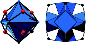
Metal–organic frameworks (MOFs) have attracted tremendous interest during the past two decades, and several thousands of structures have been reported.1 Such compounds are based on inorganic cations or metal–oxo clusters which are connected most often by polycarboxylic acids to yield frameworks with sometimes enormous porosity. Among this ever-growing number of compounds, materials based on Zr4+ ions have increasingly become the focus of research, given their outstanding chemical and thermal stability which are hardly paralleled by MOFs based on other cations.2 These remarkable properties are usually attributed to the high charge and strong oxophilicity of the Zr4+ ion. Such compounds are moreover found to exhibit promising properties especially in catalysis and adsorption applications. The coordination sphere of the Zr4+ ions can be manipulated via dehydration of the Zr6O4(OH)4 cluster or by the induction of defects in the structure to yield highly active Lewis acidic catalysts.3 Moreover, Zr-MOFs can be used as photocatalysts4 or, utilising functional groups residing at the linker molecules, as acid–base catalysts.5 Introducing catalytically active sites at porphyrinic linker molecules is also a promising approach to incorporate biomimetic active centres.6 Furthermore, Zr-MOFs have been tested in adsorption experiments and were found to be exceptional materials for CO2 capture7 and hydrocarbon separations.8With the exception of the MIL-140 series,2 which is based on one-dimensional Zr–oxo chains, Zr-MOFs are based on the very same inorganic building unit, a Zr6O8 cluster (Fig. 1, left), in which eight oxygen atoms are capping the faces of a Zr6 octahedron. In most cases, four O2− ions and four OH− ions coordinate to the Zr4+ centers under hydrated conditions.9 Employing aromatic polycarboxylic acids with different geometries as linker molecules has already led to the discovery of various porous frameworks containing this inorganic building unit.10 The best-known and most intensively investigated framework structure is UiO-66, in which ideally all twelve edges of the Zr6 octahedron are capped by carboxylate groups (Fig. 1, right).
This eventually leads to an eightfold square antiprismatic coordination environment for the Zr4+ ions, and thus a twelve-connected fcu framework is formed, in which the inorganic nodes are connected via terephthalate molecules (1,4-benzenedicarboxylate). However, while the impact of the size and shape of the aromatic or conjugated linker molecules on the resulting crystal structure has been thoroughly investigated,11 no Zr-MOFs based on aliphatic linker molecules have been reported until now. Nevertheless, this remains an interesting route to explore since aliphatic analogues of, e.g., the archetypical MIL-53 structure were already obtained,12 which exhibit substantially different properties compared to their aromatic counterparts.13 These observations inspired us to attempt the synthesis of MOFs based on Zr4+ and adipic acid (1,6-hexanedioic acid). Regarding its size, this linker molecule can be considered as a single-chain aliphatic counterpart of the most often employed terephthalic acid.
Experimental
All chemicals used for the synthesis are commercially available and were used without further purification. The syntheses were carried out in crimp cap vials with a volume of 11 mL which were placed in a preheated copper block.Synthesis
For the synthesis of [Zr6(OH)16(O2C–C4H7CH3–CO2)4]·nH2O (1), a mixture of 480 mg (3 mmol) of 3-methyladipic acid (racemic mixture), 966 mg (3 mmol) of ZrOCl2·8H2O, 5 mL of water and 800 μL of concentrated aqueous HCl was heated to 90 °C under stirring for 20 h. The white solid was filtered, washed with water and acetone and dried on the filter.To synthesise [Zr6(OH)12(SO4)4(O2C–C4H8–CO2)2(H2O)4]·nH2O (2), a mixture of 292 mg (2 mmol) of adipic acid, 710 mg (2 mmol) of Zr(SO4)2·4H2O and 5 mL of water was heated to 90 °C under stirring for 20 h. The white product was filtered, washed with water and acetone and dried on the filter.
For the synthesis of [Zr6(OH)10(Cr2O7)3(O2C–C4H8–CO2)4]·nH2O (3), a mixture of 292 mg (2 mmol) of adipic acid, 500 mg (2 mmol) of ZrO(NO3)2·xH2O, 1550 mg (8 mmol) of K2CrO4, 4 mL of water and 1 mL of concentrated nitric acid was heated to 90 °C under stirring for 20 h. The brownish red solid was filtered, washed with water and acetone and dried on the filter.
Characterisation
High-resolution PXRD data were collected from glass capillaries (diameter 0.7 mm) using a PANalytical Empyrean diffractometer (CuKα radiation) in transmission geometry for compounds 1 and 3. For compound 2, the data were collected using a STOE Stadi P diffractometer with Cu-Kα1 radiation in Debye–Scherrer geometry. Thermogravimetric experiments were carried out under a flow of oxygen using a TA Instruments Q500 at a heating rate of 10 °C min−1. IR spectra were measured with a Bruker IFS 66 v/s using KBr discs. EDX data were measured using a Philips ESEM XL30 after sputtering the sample with carbon. Force field calculations for structural optimisation were performed using Materials Studio,14 and all processing of PXRD data was carried out using TOPAS Academic.15Results and discussion
Structure determination
Structure determination from powder X-ray diffraction (PXRD) data can be an elaborate and sometimes futile process, especially when no further structural information (e.g. NMR or EXAFS data) is available. To bypass this, we used an uncommon approach. We assumed, based on the available literature, that the inorganic building units are similar or identical to the ones observed for UiO-66, since this is without doubt the most frequently observed inorganic node in Zr-MOFs. In addition, we then attempted to deduce the arrangement of these Zr–oxo clusters in space from crystal structures that have already been reported using supergroup–subgroup relationships. This process always started with the indexing of the experimental pattern. Subsequently, we tried to identify symmetry relationships between the indexed cell and the known Zr-MOFs. In a next step, the structure known from the literature was converted to a hypothetical crystal structure exhibiting the symmetry obtained by indexing using PowderCell.16 It is worth noting that this procedure reduces the symmetry, while it preserves the packing mode of the inorganic building units. This procedure was applied for compounds 1 and 3, starting with the crystal structure of UiO-66. The supergroup–subgroup sequence used for 1 was Fm![[3 with combining macron]](https://www.rsc.org/images/entities/char_0033_0304.gif) m → I4/mmm → P4/mnc. For 3, the sequence found was Fm
m → I4/mmm → P4/mnc. For 3, the sequence found was Fm![[3 with combining macron]](https://www.rsc.org/images/entities/char_0033_0304.gif) m → I4/mmm → Fmmm → Fmm2. In the case of 2, the arrangement (or packing) of the clusters is related to the structure of the Zr-MOF PCN-225 and the sequence used is I41/amd → I41/a. In these first models, the original linker molecules were deleted and/or replaced by the employed ones in appropriate positions. The cell parameters were then adjusted to the values obtained from indexing and these first models were optimised by force field calculations (Universal Force Field) using Materials Studio, yielding the second models. The ratios of Zr/S in 2 and Zr/Cr in 3 were measured by EDX spectroscopy. The corresponding number of inorganic anions was then inserted into the second models in the most plausible positions and the obtained model was again optimised by force field methods to give starting points for Rietveld refinements. For 1, the linker molecules were treated as rigid bodies adapting an extended linear conformation, while all other atoms in 1 as well as the structures of 2 and 3 were freely refined. The partial occupancies of the inorganic anions in 3 were limited to values matching with the measured EDX spectra. Residual electron densities inside the cavities of the frameworks were modelled as partially occupied oxygen atoms. However, based on further characterisation, it can be anticipated that other guest species like residual linker molecules are present inside the cavities, and thus these atoms just serve as placeholders for guest molecules. Some relevant parameters of the refinements are summarised in Table 1. We would like to point out that we observed two polymorphs of 2 which differ only by two peaks of very low, albeit varying intensities (see the ESI†). While the compound exhibiting I41/a symmetry was used for Rietveld refinement, the two weak additional peaks indicate a slight distortion towards lower symmetry (e.g. space group P
m → I4/mmm → Fmmm → Fmm2. In the case of 2, the arrangement (or packing) of the clusters is related to the structure of the Zr-MOF PCN-225 and the sequence used is I41/amd → I41/a. In these first models, the original linker molecules were deleted and/or replaced by the employed ones in appropriate positions. The cell parameters were then adjusted to the values obtained from indexing and these first models were optimised by force field calculations (Universal Force Field) using Materials Studio, yielding the second models. The ratios of Zr/S in 2 and Zr/Cr in 3 were measured by EDX spectroscopy. The corresponding number of inorganic anions was then inserted into the second models in the most plausible positions and the obtained model was again optimised by force field methods to give starting points for Rietveld refinements. For 1, the linker molecules were treated as rigid bodies adapting an extended linear conformation, while all other atoms in 1 as well as the structures of 2 and 3 were freely refined. The partial occupancies of the inorganic anions in 3 were limited to values matching with the measured EDX spectra. Residual electron densities inside the cavities of the frameworks were modelled as partially occupied oxygen atoms. However, based on further characterisation, it can be anticipated that other guest species like residual linker molecules are present inside the cavities, and thus these atoms just serve as placeholders for guest molecules. Some relevant parameters of the refinements are summarised in Table 1. We would like to point out that we observed two polymorphs of 2 which differ only by two peaks of very low, albeit varying intensities (see the ESI†). While the compound exhibiting I41/a symmetry was used for Rietveld refinement, the two weak additional peaks indicate a slight distortion towards lower symmetry (e.g. space group P![[4 with combining macron]](https://www.rsc.org/images/entities/char_0034_0304.gif) ). Such distortional phenomena have been observed previously for the UiO-66 framework as well.17
). Such distortional phenomena have been observed previously for the UiO-66 framework as well.17
| Compound | 1 | 2 | 3 |
|---|---|---|---|
| Space group | P4/mnc | I41/a | Fmm2 |
| a/Å | 11.5042(4) | 14.9579(5) | 16.6935(13) |
| b/Å | 11.5042(4) | 14.9579(5) | 16.6920(11) |
| c/Å | 24.7857(12) | 29.1046(12) | 24.7658(27) |
| α = β = γ/° | 90 | 90 | 90 |
| V/Å3 | 3280.3(2) | 6511.8(4) | 6900.9(10) |
| R WP/% | 4.5 | 4.5 | 8.0 |
| R Bragg/% | 0.8 | 0.7 | 4.4 |
| GoF | 3.2 | 1.5 | 4.2 |
While the R values are satisfying, the GoF for 1 and 3 are rather high. We attribute this mostly to the fact that the assignment of the residual electron density to oxygen atoms is not sufficient to accurately model the pore content in these structures. This is substantiated by the observation of protonated carboxylic acid groups of linker molecules in the respective IR spectra, which might be occluded inside the cavities. Moreover, the proximity of residual electron densities to framework atoms in 3 and to a lesser extent in 2 leaves us with the assumption that the described frameworks have a certain degree of disorder, which cannot unambiguously be modelled by PXRD methods. This disorder likely originates from the conformational flexibility of the linker molecules and the dichromate species.
The Rietveld plots are shown in Fig. 2 and further crystallographic information can be found in the ESI.† From these plots and from the cell parameters, it is already obvious that the structures of 1 and 3 are related to each other. Actually, a tetragonal model for 3 was set up as well since the extinction conditions match well with the tetragonal symmetry. However, all attempts to refine such a tetragonal model were unsuccessful, which indicated a lower symmetry, i.e. orthorhombic symmetry.
Crystal structures and properties
All three crystal structures are based on the inorganic building unit which is shown in Fig. 1. However, the coordinating moieties and the geometric arrangements of these moieties substantially differ from one material to another.Employing adipic acid and ZrOCl2·8H2O or ZrO(NO3)2·xH2O in water, only products of low crystallinity could be obtained, irrespective of the synthesis temperature and the molar ratios of the reactants or additives like mineral acids. Replacing the linker molecule with 3-methyladipic acid allowed for the synthesis of highly crystalline 1, which we assume to be a well-ordered substituted analogue of the product obtained using adipic acid (see the ESI† for comparison of PXRD data). This induction of higher crystallinity could be, e.g., due to stronger interactions inside the framework or lower conformational flexibility of the methyladipate molecules compared to that of adipate molecules, possibly resulting in a less disordered arrangement.
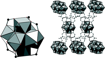
In the structure of 1, eight carboxylate groups are coordinated to the Zr6O8 core. The structure can be derived from the twelve-connected structure of UiO-66, if four groups coordinating in the equatorial plane of the cluster are omitted (Fig. 3, left). It was reported that under acidic and aqueous conditions, the Zr6O8 cluster is in fact a Zr6(OH)8 cluster.18 Anticipating that the composition inside this framework is similar, we propose the formula [Zr6(OH)16(O2C–C4H7CH3–CO2)4]·nH2O. Thus, we assume that all coordinating oxygen atoms in the equatorial plane of the cluster are part of the OH− ions. However, based on the measured data, it cannot be excluded that OH− ions are partially replaced by H2O molecules and/or O2− ions.
This connectivity results in a uninodal net with bcu topology. The cavities observed are occupied by guest molecules. The linker molecule 3-methyladipate possesses a chiral centre, but since a racemic mixture was employed for the synthesis, the CH3 substituents are statistically distributed over the four possible positions (Fig. 3, right).
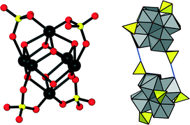
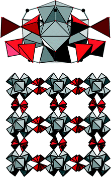
Drastically different coordination chemistry is observed in 2. In this compound, four SO42− ions are coordinated to the inorganic cluster in a bidentate fashion. The arrangement of these anions corresponds to the corners of a tetrahedron. According to the observed bond lengths, these sulfate ions are also interacting with OH groups at adjacent inorganic clusters via hydrogen bonds (Fig. 4). Combining these binding modes, a purely inorganic hydrogen-bonded framework of zirconium sulfate clusters with dia topology is observed in 2 as a substructure.
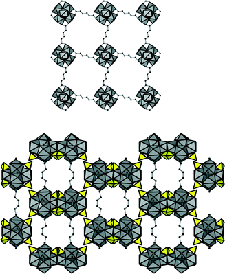
In addition, four carboxylate groups of the organic linker molecules are coordinating in the equatorial plane of the cluster, leading to a square grid layer based on inorganic nodes and adipate anions. This eventually results in an open framework structure (Fig. 5) virtually completely filled with guest molecules. Based on the assumption that the core of the cluster is represented by the formula Zr6(OH)816+ (as assumed also for 1), the composition of the framework of 2 was deduced to be [Zr6(OH)12(SO4)4(O2C–C4H8–CO2)2(H2O)4]·nH2O.
The structural differences between 1 and 2 indicate a very strong effect of inorganic anions on the connectivity of the Zr–oxo cluster. To the best of our knowledge, no similarity to the direct coordination of sulfate ions in 2 has been reported yet for the hexanuclear zirconium cluster. Similar coordination modes have only been observed in compounds based on an octadecanuclear Zr–oxo cluster19 or on heptadecanuclear20 and nonanuclear21 Hf–oxo species. In Zr-MOF chemistry, such a binding mode has not yet been observed since only ZrCl4, ZrOCl2·8H2O and ZrO(NO3)2·xH2O are generally employed for the synthesis of Zr-MOFs. Apparently, the nature of the inorganic counterion can play a major role in the coordination chemistry of Zr-MOFs. This could be caused by, for example, the higher charge of SO42− compared to that of Cl− or NO3−. Moreover, the bidentate nature of sulfate may lead to a chelating effect. An indication that this effect is already present in solution was recently given in a study of the chemistry of Zr4+ in aqueous solutions as a function of the concentration of sulfate ions.19
This coordinating effect inspired us to further investigate the role of inorganic anions in the synthesis of zirconium adipates. Replacing Zr(SO4)2·4H2O by the oxynitrate and adding Na2S2O3 or Na2SO4 in an amount corresponding to the amount of SO42− in the synthesis of 2 under otherwise identical synthesis conditions indeed lead to the formation of Zr adipates. The PXRD patterns are comparable to those measured for 2, but due to the lower crystallinity no further characterization was carried out.
Adding K2CrO4 to the mixture of ZrO(NO3)2·xH2O and adipic acid in water yields a yellow crystalline powder after heating. However, the strongest peaks seem to be present as duplets with a small shift (see the ESI†). The ratio of intensities of these twin peaks can be changed by adjusting the pH, and under highly acidic conditions, pure 3 was obtained. Thus, we assume that the impure yellow solid obtained at higher pH incorporates the yellow CrO42− ions, while the higher acidity in the synthesis of 3 shifts the chromate–dichromate equilibrium. In this way, only dichromate is incorporated into the framework of 3 which is also suggested by its brownish red colour. Based on the analytical results, the composition of the framework of 3 is given by the formula [Zr6(OH)10(Cr2O7)3(O2C–C4H8–CO2)4]·nH2O.
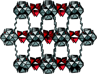
In the structure of 3, each Cr2O72− ion is coordinated twofold in a monodentate way to two zirconium clusters; the dichromate species thus interconnect the inorganic nodes. The dichromate anions are partially occupying two different positions, and therefore purely inorganic square grid layers are observed (Fig. 6).
When no dichromate is present, the respective position is occupied by OH groups. The remaining coordination sites at the Zr clusters are occupied by eight carboxylate groups, and thus a bcu framework of Zr–oxo clusters and adipate molecules is formed. Thus, the essential difference between 1 and 3 is the incorporation of interconnecting dichromate ions in 3. The complete framework structure is shown in Fig. 7.
While all three compounds discussed herein contain potential voids, the thermal removal of these molecules at 100 °C invariably leads to an irreversible and strong decrease in crystallinity. We assume that the flexible adipate molecules, unlike terephthalate molecules, do not possess sufficient rigidity to maintain the crystalline ordering in the described structures once the guest molecules are removed.
It is remarkable that among the anions present in the different synthesis mixtures, only the sulfate anions are substantially affecting the framework topology. The effect of strong interaction is already present in solution,19 and the nature of the species in solution was reported to depend strongly on the concentration of sulfate. This is also confirmed in our study by the occurrence of another yet unidentified compound (see the ESI† for PXRD) when the synthesis of 2 is carried out under diluted conditions, indicating an even more diverse concentration-dependent coordination chemistry. In contrast to this, chloride, nitrate, chromate or dichromate in the solution all lead to the same bcu topology which therefore may be anticipated to be the thermodynamically preferred framework for zirconium adipates.
The IR spectra (Fig. 8) of the three compounds all show a broad absorption around 3400 cm−1 due to the incorporation of water molecules inside the framework's cavities. For compounds 1 and 3, there are also signals around 1700 cm−1 which indicate that residual protonated linker molecules might be present inside the pores. The signal at 1640 cm−1 in the spectrum of 2 is attributed to the δ-OH modes. The signals between 1580 cm−1 and 1440 cm−1 are due to asymmetric and symmetric carboxylate vibrations of the linker molecules. Signals at 1130, 1065 and 605 cm−1 in the spectrum of 2 further confirm the presence of sulfate inside the framework. The signals at 950 and 890 cm−1 in the spectrum of 3 are assigned to the presence of dichromate ions.
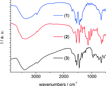 | ||
| Fig. 8 Infrared spectra of (from top to bottom) the methyladipate 1, the adipate/sulfate 2 and the adipate/dichromate 3. | ||
The thermogravimetric curves measured at a heating rate of 10 °C min−1 under a flow of oxygen indicate that for all three compounds substantial amounts of water are removed from the pores up to a temperature of ~100 °C (see the ESI†). However, as already mentioned, the crystallinity is strongly decreased upon solvent removal and thus the framework structure is not maintained upon thermal treatment. The full decomposition of the samples starts between 250 °C and 300 °C. The expected and observed steps of mass loss are summarized in the ESI.† The observed values are in reasonable agreement with the expected ones, but especially for compound 1, the presence of additional guest molecules leads to a larger weight loss value than expected for a guest-free framework.
Conclusions
The synthesis of the three new compounds clearly demonstrates that aqueous synthesis conditions can be well suitable for the discovery of new Zr-MOFs. The diversity of aliphatic polycarboxylic acids could allow for the synthesis of many more compounds. Moreover, the impact of inorganic anions on the obtained crystal structures holds great promise to induce the formation of new Zr-MOFs which hopefully could be employed as well for the synthesis of more rigid frameworks with permanent porosity. This is especially of interest, taking into account the requirements for a large-scale synthesis, which should exclude the utilisation of, e.g., chlorides and nitrates due to corrosion and safety issues.22 Thus, we are currently investigating whether rigid aromatic linker molecules can be employed as well under similar synthesis conditions.Acknowledgements
DDV thanks IWT (Vlaanderen) for support in the SBO project MOFShape, KU Leuven for CASAS Methusalem funding, FWO for research projects G.0486.12 and G.0256.14 and for fellowships to IS, BB and RA, and Belspo for funding in IAP 7/05.Notes and references
- H. Furukawa, K. E. Cordova, M. O'Keeffe and O. M. Yaghi, Science, 2013, 341, 974 CrossRef CAS PubMed.
- M. Kandiah, M. H. Nilsen, S. Usseglio, S. Jakobsen, U. Olsbye, M. Tilset, C. Larabi, E. A. Quadrelli, F. Bonino and K. P. Lillerud, Chem. Mater., 2010, 22, 6632 CrossRef CAS; V. Guillerm, F. Ragon, M. Dan-Hardi, T. Devic, M. Vishnuvarthan, B. Campo, A. Vimont, G. Clet, Q. Yang, G. Maurin, G. Ferey, A. Vittadini, S. Gross and C. Serre, Angew. Chem., Int. Ed., 2012, 51, 9267 CrossRef PubMed.
- P. Valvekens, F. Vermoortele and D. De Vos, Catal. Sci. Technol., 2013, 3, 1435 Search PubMed; F. Vermoortele, B. Bueken, G. Le Bars, B. Van de Voorde, M. Vandichel, K. Houthoofd, A. Vimont, M. Daturi, M. Waroquier, V. Van Speybroeck, C. Kirschhock and D. De Vos, J. Am. Chem. Soc., 2013, 135, 11465 CrossRef CAS PubMed.
- C. Gomes Silva, I. Luz, F. X. Llabres i Xamena, A. Corma and H. Garcia, Chem. – Eur. J., 2010, 17, 11133 CrossRef PubMed.
- F. Vermoortele, R. Ameloot, A. Vimont, C. Serre and D. De Vos, Chem. Commun., 2011, 47, 1521 RSC.
- Y. Chen, T. Hoang and S. Ma, Inorg. Chem., 2012, 51, 12600 CrossRef CAS PubMed.
- Q. Yang, S. Vaesen, F. Ragon, A. D. Wiersum, D. Wu, A. Lago, T. Devic, C. Martineau, F. Taulelle, P. L. Llewellyn, H. Jobic, C. Zhong, C. Serre, G. De Weireld and G. Maurin, Angew. Chem., Int. Ed., 2013, 52, 10316 CrossRef CAS PubMed.
- P. S. Bárcia, D. Guimarães, P. A. P. Mendes, J. A. C. Silva, V. Guillerm, H. Chevreau, C. Serre and A. E. Rodrigues, Microporous Mesoporous Mater., 2011, 139, 67 CrossRef CAS PubMed; T. Duerinck, R. Bueno-Perez, F. Vermoortele, D. De Vos, S. Calero, G. V. Baron and J. F. M. Denayer, J. Phys. Chem. C, 2013, 117, 12567 Search PubMed.
- L. Valenzano, B. Civalleri, S. Chavan, S. Bordiga, M. H. Nilsen, S. Jakobsen, K. P. Lillerud and C. Lamberti, Chem. Mater., 2011, 23, 1700 CrossRef CAS.
- J. H. Cavka, S. Jakobsen, U. Olsbye, N. Guillou, C. Lamberti, S. Bordiga and K. P. Lillerud, J. Am. Chem. Soc., 2008, 130, 13850 CrossRef CAS PubMed; V. Bon, V. Senkovskyy, I. Senkovska and S. Kaskel, Chem. Commun., 2012, 84, 8407 RSC; A. Schaate, P. Roy, A. Godt, J. Lippke, F. Waltz, M. Wiebcke and P. Behrens, Chem. – Eur. J., 2011, 17, 6643 CrossRef PubMed; W. Morris, B. Volosskiy, S. Demir, F. Gándara, P. L. McGrier, H. Furukawa, D. Cascio, J. F. Stoddart and O. M. Yaghi, Inorg. Chem., 2012, 51, 6443 CrossRef PubMed; D. Feng, Z.-Y. Gu, J.-R. Li, H.-L. Jiang, Z. Wei and H.-C. Zhou, Angew. Chem., Int. Ed., 2012, 51, 10453 CrossRef; H.-L. Jiang, D. Feng, K. Wang, Z.-Y. Gu, Z. Wei, Y.-P. Chen and H.-C. Zhou, J. Am. Chem. Soc., 2013, 135, 13934 CrossRef PubMed; H. Furukawa, F. Gándara, Y. Zhang, J. Jiang, W. L. Queen, M. R. Hudson and O. Yaghi, J. Am. Chem. Soc., 2014, 136, 4369 CrossRef PubMed; W. Liang, H. Chevreau, F. Ragon, P. D. Southon, V. K. Peterson and D. M. D'Alessandro, CrystEngComm, 2014, 16, 6530 RSC.
- V. Bon, I. Senkovska, I. A. Baburin and S. Kaskel, Cryst. Growth Des., 2013, 13, 1231 Search PubMed; G. Wißmann, A. Schaate, S. Lilienthal, I. Bremer, A. M. Schneider and P. Behrens, Microporous Mesoporous Mater., 2012, 152, 64 CrossRef CAS PubMed; A. Schaate, P. Roy, T. Preuße, S. J. Lohmeier, A. Godt and P. Behrens, Chem. – Eur. J., 2011, 17, 9320 CrossRef PubMed; V. Bon, I. Senkovska, M. S. Weiss and S. Kaskel, CrystEngComm, 2013, 15, 9572 RSC; W. Zhang, H. Huang, D. Liu, Q. Yang, Y. Xiao, Q. Ma and C. Zhong, Microporous Mesoporous Mater., 2013, 171, 118 CrossRef PubMed.
- F. Niekiel, M. Ackermann, P. Guerrier, A. Rothkirch and N. Stock, Inorg. Chem., 2013, 52, 8699 CrossRef CAS PubMed; I. H. Kim, X. Wang and A. J. Jacobson, Solid State Sci., 2010, 12, 76 CrossRef PubMed; L. Wang, T. Song, C. Li, J. Xia, S. Wang, L. Wang and J. Xu, J. Solid State Chem., 2012, 190, 208 CrossRef PubMed.
- F. Niekiel, J. Lannoeye, H. Reinsch, A. S. Munn, A. Heerwig, I. Zizak, S. Kaskel, R. I. Walton, D. de Vos, P. Llewellyn, A. Lieb, G. Maurin and N. Stock, Inorg. Chem., 2014, 53, 4610 CrossRef CAS PubMed.
- Materials Studio Version 5.0, Accelrys Inc., San Diego, CA, 2009 Search PubMed.
- Topas Academics 4.2, Coelho Software, 2007 Search PubMed.
- W. Kraus and G. Nolze, PowderCell 2.4, 2000 Search PubMed.
- S. Jakobsen, D. Gianolio, D. S. Wragg, M. H. Nilsen, H. Emerich, S. Bordiga, C. Lamberti, U. Olsbye, M. Tilset and K. P. Lillerud, Phys. Rev. B: Condens. Matter Mater. Phys., 2012, 86, 125429 CrossRef.
- L. Pan, R. Heddy, J. Li, C. Zheng, X.-Y. Huang, X. Tang and L. Kilpatrick, Inorg. Chem., 2008, 47, 5537 CrossRef CAS PubMed.
- Y.-J. Hu, K. E. Knope, S. Skanthakumar, M. G. Kanatzidis, J. F. Mitchell and L. Soderholm, J. Am. Chem. Soc., 2013, 135, 14240 CrossRef CAS PubMed; P. J. Squattrito, P. R. Rudolf and A. Clearfield, Inorg. Chem., 1987, 26, 4240 CrossRef.
- S. J. Dalgarno, J. L. Atwood and C. L. Raston, Inorg. Chim. Acta, 2007, 360, 1344 CrossRef CAS PubMed.
- A. Kalaji and L. Soderholm, Chem. Commun., 2014, 50, 997 RSC.
- M. Gaab, N. Trukhan, S. Maurer, R. Gummaraju and U. Müller, Microporous Mesoporous Mater., 2012, 157, 131 CrossRef CAS PubMed.
Footnote |
| † Electronic supplementary information (ESI) available: Additional PXRD data, crystallographic information and thermogravimetric data. See DOI: 10.1039/c4ce01457j |
| This journal is © The Royal Society of Chemistry 2015 |

