Recent advances in two-dimensional nanomaterials as bifunctional electrocatalysts for full water splitting
Cui
Xu
a,
Mengyang
Zhang
a,
Xianjun
Yin
a,
Qiang
Gao
a,
Shuai
Jiang
a,
Junye
Cheng
d,
Xin
Kong
*bc,
Bin
Liu
 *a and
Hui-Qing
Peng
 *a
*a
aState Key Laboratory of Chemical Resource Engineering, Beijing Advanced Innovation Center for Soft Matter Science and Engineering, College of Chemistry, Beijing University of Chemical Technology, Beijing, 100029, P. R. China. E-mail: binliu@buct.edu.cn; hqpeng@mail.buct.edu.cn
bCenter of Super-Diamond and Advanced Films (COSDAF) and Department of Materials Science and Engineering, City University of Hong Kong, HK SAR, China
cKunming University of Science and Technology, Department of Materials Science and Engineering, Kunming, 650504, P. R. China. E-mail: xinkong2-c@my.cityu.edu.hk
dDepartment of Materials Science, Shenzhen MSU-BIT University, Shenzhen, 517182, P. R. China
First published on 11th August 2023
Abstract
Two-dimensional (2D) nanomaterials are some of the most promising bifunctional electrocatalysts that can simultaneously catalyze the hydrogen evolution reaction (HER) and oxygen evolution reaction (OER). They have attracted extensive attention owing to their decent electrocatalytic performance and cost advantages. In this review, we first provide an overview of 2D bifunctional electrocatalyst categories including layered double hydroxides, graphitic carbon nitride, metal–organic frameworks, transition metal dichalcogenides, and transition metal carbon/nitrogen compounds, and discuss their structures and synthesis methods, presenting detailed discussion on how the special 2D systems are synthesized and characterized experimentally, which complement a comprehensive understanding of the characteristics of 2D bifunctional electrocatalysts. Moreover, we focus on the recent development of 2D nano-catalysts with both HER and OER activity in the field of overall water splitting and summarize some typical strategies for enhancing the bifunctional activities, including doping, nanocomposite construction, interface formation, defect engineering and morphology modulation. The structure–activity relationships are also discussed with the aim of providing guidance in designing novel 2D bifunctional electrocatalysts. Finally, we explore some of the challenges and perspectives that remain in this rapidly growing field. We believe that the systematic and comprehensive contents of this review will stimulate wider research and attention.
1. Introduction
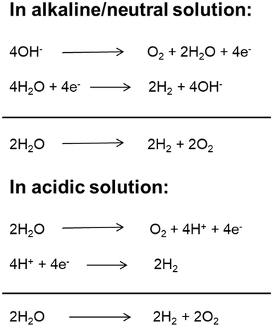
With a growing population and rapid economic development, the global energy demand will continue to grow in the future. Fossil fuels (coal, oil, natural gas, etc.) have always been the main energy source for the global economy and society due to their high energy and easy access.1 However, the overuse of fossil fuels has caused serious energy crises and environmental pollution. Therefore, it is significant to develop and utilize clean renewable energy to substitute conventional energies.2 Hydrogen is a renewable, clean, zero-carbon-emission secondary energy. At present, most hydrogen is produced from fossil resources through steam reforming processes, which increases the consumption of fossil fuels and emissions of carbon dioxide. Among the developed technologies, producing molecular hydrogen from cheap and plentiful water through electrolysis technology has been widely regarded as a promising approach due to its simple conversion process, cleanliness, flexibility and high purity of hydrogen production.3,4 Although water electrolysis technology has been developed and applied in the two centuries since it was first reported,5,6 its widespread application is limited because of its high energy consumption and high cost.7 The electrolytic water splitting reaction includes two half reactions: cathodic hydrogen evolution reaction (HER) and anodic oxygen evolution reaction (OER).8 Depending on the reaction environment (acidic, neutral or basic), the two half-reactions of water electrolysis can be expressed in different ways as shown in Fig. 1. Under standard conditions (25 °C and 1 atm), the ΔG of the water splitting reaction is 237.1 kJ mol−1, corresponding to a thermodynamic potential of 1.23 V.9 However, the adverse factors of electrode materials (such as activation energy and ion and gas diffusion) and device-related factors (such as solution concentration, wire and electrode resistance, electrolyte diffusion blockage, bubble formation, and heat release) result in a large overpotential during electrolysis. Therefore, the actual potential of water electrolysis is always far higher than the theoretical minimum value (commercial cells usually work at a voltage of 1.8–2.0 V).10 Therefore, exploring suitable catalysts to reduce the reaction overpotential and increase the reaction rate and thus the total electrolysis efficiency is the current research direction. An ideal catalyst for water electrolysis must meet two basic requirements. First, the catalyst must be highly active and have a minimum overpotential to produce a high current density. Second, the catalyst must have long-term stability. Hence, the development of electrocatalysts possessing high activity and stability will be favorable for the advancement of the large-scale applications of electrolysis-related technologies. Earlier, Pt was used for the HER, while RuO2 and IrO2 were used for the OER.11–15 However, their scarcity, high cost and non-bifunctional properties hamper the application in large-scale water splitting. In most of the cases, the electrocatalysts show high HER performance but worse performance for the OER in acidic medium, and high OER performance but inferior performance for the HER in alkaline medium.16 At the same time, to meet the practical application requirements, the HER and OER should be carried out in the same electrolyte utilizing a single catalyst to achieve full water splitting. However, the current prevailing water splitting requires the integration of two types of catalysts that are especially suitable for the HER and OER, respectively. Such a combination is usually incompatible and thus results in a poor overall performance. Therefore, the development of bifunctional catalysts, which are highly active for both the HER and OER, is of prime importance for full water splitting.Two-dimensional (2D) nanomaterials are regarded as some of the most promising electrocatalysts for the HER and OER.17–22 The significance and irreplaceability of 2D nano-catalysts can be demonstrated as follows: (1) 2D nanomaterials have high specific surface areas (maximal surface to bulk ratio), copious surface and edge-exposed sites, high morphological anisotropy, tunable chemical composition, and unique electronic structure; (2) most 2D catalysts could serve as ideal platforms to couple with other materials or substrates compared with the bulk catalyst; (3) 2D catalysts can be easily activated and optimized for enhanced activity by some activation strategies; (4) 2D catalysts can be used as an ideal model to investigate the relationship between the exposed active sites and the catalytic activity, revealing the catalytic mechanism. In 2004, Geim and Novoselov isolated graphene for the first time by stripping graphite.23 Since then, researchers have discovered a series of 2D nanomaterials with similar layered structural characteristics, including layered double hydroxides (LDHs), graphite phase carbon nitride (g-C3N4), 2D metal–organic frameworks (MOFs), transition metal dichalcogenides (TMDs) and transition metal carbon/nitrogen compounds (MXenes) and 2D metal nanomaterials, which have attracted extensive research interest in electrocatalytic due to their unique surface chemistry properties and high specific surface area. With the development of electrocatalysts used for water electrolysis, 2D nanomaterials have been found to be electrocatalytically active toward the OER or HER. In particular, 2D bifunctional catalysts that can simultaneously catalyze the HER and OER (i.e., full water splitting) have attracted extensive attention because of their decent catalytic performance and cost advantage. In spite of the great advances, no review is available that is exclusively dedicated to introducing the advances in 2D nanomaterials as bifunctional electrocatalysts for full water splitting, with a particular emphasis on activation strategies for improving bifunctional catalytic activities so far. Moreover, the catalytic activity origin of electrocatalysts is unclear due to the frequent lack of deep insights into the catalytic reaction mechanism at the atomic level, and especially the discussion of the effect of their electronic structure and morphology on catalytical properties is still limited.24–26 Thus, we would like to make a comprehensive summary and induction of the progress of 2D electrocatalysts used for overall water splitting (considering the relatively limited reports on 2D metal nanomaterials as bifunctional electrocatalysts,27–29 this review does not introduce it detail), so as to provide reference and guidance for researchers in related fields.
In this review, we will first provide an overview of 2D bifunctional electrocatalyst categories, including layered double hydroxides, graphitic carbon nitride, metal–organic frameworks, transition metal dichalcogenides, and transition metal carbon/nitrogen compounds, and discuss their structures and synthesis methods, presenting detailed discussion on how the special 2D systems are synthesized and characterized experimentally which will complement a comprehensive understanding on the characteristics of 2D bifunctional electrocatalysts. Then, we will summarize the effective activation strategies of 2D bifunctional electrocatalysts including doping, defect engineering, nanocomposite construction, interface formation and morphology engineering (Fig. 2). Meanwhile, the relationship between the structure and performance of 2D catalysts will be discussed. Finally, perspectives on the challenges and opportunities in developing new 2D cost-effective and high-efficiency bifunctional electrocatalysts for practical applications will be outlined, which will provide valuable insights for the development of novel 2D bifunctional electrocatalysts with high performance.
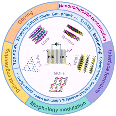 | ||
| Fig. 2 The schematic picture showing two-dimensional nanomaterials about their structures, synthesis methods and activation strategies in the field of overall water splitting. | ||
2. Structure of two-dimensional nanomaterials
2.1 Layered double hydroxides (LDHs)
LDHs are a class of 2D anionic clay materials, which is a general term for hydrotalcite and hydrotalcite like compounds. As shown in Fig. 3a, their general expression is [M2+1−xMx3+(OH)2]x+[Ax/nn−]·mH2O,1 where M2+ and M3+ represent the metal cations respectively, and m represents interlamellar water volume. Ax/nn− is the intercalation anion, and the x value is equal to the mole ratio of M2+/(M2++M3+), and the x value ranges from 0.2 to 0.33. In terms of expression, LDHs are mainly composed of three parts: main laminate, interlayer anions and solvent molecules. The main laminate is composed of divalent metal cations M2+ (Ca2+, Fe2+, Mg2+, Zn2+, etc.) and trivalent metal cations M3+ (Fe3+, Ni3+, Ti3+, Cr3+, etc.). The interlayer is mainly occupied by intercalated anions (OH−, NO3−, CO32−, HCO3−, etc.), and solvent molecules are mainly water molecules between the main laminates.30 Generally speaking, M2+ and M3+ metal ions are the active sites in catalytic reactions of LDHs.31,32 LDHs with different properties and functions can be obtained by adjusting the type of metal cation, the mole ratio of M2+/M3+ and the anions in solution. LDHs have attracted great interest in energy storage/conversion, chemical sensing, magnetism, optics, biomedical science, and other fields due to their tunability of composition and the structure, simplicity of the synthesis process and uniqueness of physical and chemical properties.33–39 At present, many kinds of LDHs are successfully applied in the catalytic electrolysis of water reaction and show good results due to their excellent electrical conductivity and structural stability. Since 2009, there has been an explosion of publications on LDH-based materials employed as efficient electrocatalysts.39–41 In order to promote the performance of LDH-based electrocatalysts, some strategies including modification of carbon materials, defect engineering, and loading of noble metals could be adopted, which will be discussed in a later chapter.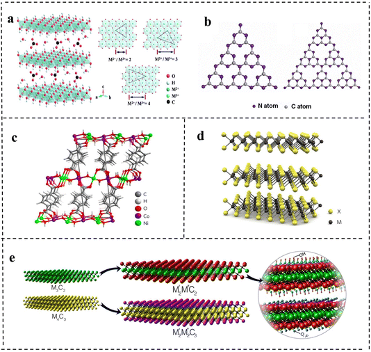 | ||
| Fig. 3 The schematic structures of (a) layered double hydroxides (LDHs). Reproduced with permission from ref. 30. Copyright 2020, Elsevier. (b) Graphite phase carbon nitride (g-C3N4). Reproduced with permission from ref. 46. Copyright 2017, American Chemical Society. (c) Metal–organic frameworks (MOFs). Reproduced with permission from ref. 56. Copyright 2016, Springer Nature. (d) Transition metal dichalcogenides (TMDs). Reproduced with permission from ref. 61. Copyright 2012, Springer Nature. (e) Transition metal carbon/nitrogen compounds (MXenes). Reproduced with permission from ref. 66. Copyright 2015, American Chemical Society. | ||
2.2 Graphite phase carbon nitride (g-C3N4)
g-C3N4, a metal-free polymeric material, is one of the oldest 2D materials in the record of scientific literature, and has a high nitrogen content and similar planar structure to graphene.42 Its history can be traced back to 1834, when Berzelius successfully synthesized a carbon nitride compound, which was named by Liebig. Subsequently, in 1996, Teter et al.43 used first-principles methods to accurately calculate the structure of carbon nitride compounds and proposed five different crystal structures of carbon nitride: α-C3N4 phase, β-C3N4 phase, cubic C3N4 phase, quasi-cubic C3N4 phase and graphite-like C3N4 phase. Among them, the structure of graphite-like C3N4 (g-C3N4) is the most stable. The highly delocalized π conjugated system is formed by sp2 hybridization between C atoms and N atoms. Studies have found that the basic structural units of g-C3N4 are two allotropes of g-C3N4, a triazine ring (C3N3) and a heptazine ring (C6N7) (as shown in Fig. 3b).44–46 Kroke et al.47 calculated the binding energy of the heptazine ring unit by first-principles density functional theory (DFT), and it was 30 KJ mol−1, much lower than that of the triazine ring, indicating that g-C3N4 composed of the heptazine ring was more stable than the triazine ring. Therefore, the heptazine ring is generally considered to be the typical structure of g-C3N4. g-C3N4 with a heptazine ring as the structural unit is formed by sp2 hybridization, so a π conjugated plane is formed between rings through the connection of N atoms at the end of the rings, which shows considerable chemical stability (stable in acids, alkalis, and various organic solvents), thermal stability (up to 600 °C in air) and an appealing electronic structure with a suitable bandgap.48 At the same time, layers are connected by weak van der Waals force. Thus, g-C3N4 has a broad application prospect in the field of catalysis, triggering a lot of research work.At present, g-C3N4 is widely used in catalytic reactions due to its advantages of highly active sites, easy preparation, low cost and excellent photoelectric chemical properties. The application of g-C3N4 in electrochemical catalysis was first studied in 2009. Lyth et al.49 first demonstrated that g-C3N4 had higher oxygen reduction catalytic activity than carbon black in an acidic environment, but its ultralow specific surface area and weak electrical conductivity limited its catalytic activity. After mixing g-C3N4 with carbon black, the specific surface area and conductivity of the catalyst were improved and the activity was obviously enhanced. Pure g-C3N4 based compounds are not competitive in the field of electrocatalysis and have low current densities even at very high overpotentials because of the weak electrical conductivity. However, the activity of g-C3N4 can be optimized by means of hybridizing with carbon-based materials, metal or non-metal doping, and regulating the morphology and nanostructure. Since then, some researchers began to study modified g-C3N4 materials in depth to achieve enhanced catalytic activity, which had been successfully applied in water electrolysis to catalyze the HER and OER.
2.3 Metal–organic frameworks (MOFs)
A metal–organic framework is a kind of organic–inorganic hybrid material with intramolecular pores formed by self-assembly of metal ions or clusters and organic ligands through coordination bonds.50 In layered MOFs, there are strong in-plane coordination bonds, but weak interactions between layers (e.g., van der Waals forces and hydrogen bonding) as shown in Fig. 3c.42 In 1995, Yaghi et al.51 successfully synthesized 2D structural MOF materials by reacting the transition metal Co with 1,3,5-benzenetricarboxylic acid and proposed the concept of metal–organic frameworks for the first time. Different from inorganic porous materials and general organic complexes, MOFs have both the rigidity of inorganic materials and the flexibility of organic materials, possessing a designable structure, large channel, and high surface area. Basically, the metal nodes can serve as active sites for the catalytic process. Therefore, so far, MOFs have been reported to be widely used in gas storage, biocatalysis, photocatalysis, chemical sensing and other fields.52 However, when MOFs are used in electrocatalysis, the main problems are poor electrical conductivity and the instability of their own structure caused by metal nodes surrounded by organic linkers compared with other 2D nanomaterials.53,54 Accordingly, researchers have made some progress in increasing the electrical conductivity and stability of MOFs for good electrocatalytic performance by combining different metal ions or metal clusters with different organic ligands to adjust the structure.55 Many studies have shown that 2D MOFs have unique characteristics compared with gross phase MOFs, which have great potential in the field of electrocatalysis.56–58 2D MOFs allow more active sites to be exposed on the surface. Due to the lack of organic ligands, the metal sites on the surface are unsaturated, which greatly improves the catalytic activity.59 In addition, the ultrathin structure can provide a short diffusion path and fast electron charge transfer, further enhancing the catalytic activity. The diverse and tunable chemical structures of 2D MOFs provide a convenient way to fabricate a variety of efficient catalysts with bifunctional catalytic activity by expanding the surface area, incorporating bimetallic components and combining non-metallic elements. 2D MOFs also introduce better simplicity and compatibility for electrocatalytic systems. Despite many advantages, the research on bifunctional MOF-based catalysts is still in the initial stage, which faces several challenges in academic research and industrial applications.2.4 Transition metal dichalcogenides (TMDs)
Transition metal dichalcogenides are another class of 2D materials that have been extensively investigated following the unconventional properties of graphene. TMDs have attracted extensive attention because of their broad energy application prospects and striking fundamental properties.60 TMDs can be described by the chemical formula of MX2, where M refers to transition metal elements such as molybdenum (Mo), tungsten (W), niobium (Nb) and rhenium (Re). It is sandwiched between two chalcogenide X2 such as sulfur (S), selenium (Se) and tellurium (Te) with a thickness of ≤1 nm. The atoms are covalently bonded within each layer (X–M–X), and the individual layers are connected together through weak van der Waals (vdW) forces with +4 state metal and −2 state chalcogen atoms. Due to the presence of lone pairs of chalcogen atoms terminating the surface of the layers and the resulting difference in oxidation states, a significant amount of ionic character is induced between the metal and chalcogen atoms. MX2 layered structures have three thermodynamically stable structures: 2H (hexagonal symmetry and triangular prism coordination, with two layers in each repeating unit), 3R (rhombic symmetry and triangular prism coordination, with three layers in each repeating unit) and 1T (tetragonal symmetry and octahedral coordination, with one layer in each repeating unit) with a spacing of 0.7 nm (as shown in Fig. 3d).61 The unique structure of TMDs can also be visualized from the perspective of two distinct orientations characterized by surface inertness (basal planes) and high surface energy (edges), exhibiting anisotropic properties. It has been revealed that the electrical conductivity along the layer is ≈2200 times higher than that across the van der Waals force gaps between layers, predicting much faster electron transport at the edges compared to the basal planes.62 Such inherent characteristics of TMDs can give rise to prominently active catalysis in electrocatalytic reactions provided that the active edges are maximally exposed.63,642.5 Transition metal carbon/nitrogen compounds (MXenes)
MXene is a new kind of 2D material, which is divided into transition metal carbide and nitride. In 2011, Gogotsi et al.65 for the first time obtained a 2D layered transition metal carbon/nitride material (named MX) after selective etching of the A atom layer in a MAX phase. MAX phases are a large family of layered ternary transition-metal carbides or nitrides with the chemical formula Mn+1AXn (n = 1, 2, or 3), where M is a transition metal, A is an A-group element (usually IIIA or IVA group), and X is C or N. Since the M–A bond is weaker than the M–X bond, the “A” atomic layer can be selectively etched from the maximum phase using HF. Compared with the crystal structure of MAX phases, the A atomic layer of MX is missing, and the 2D structure is similar to that of graphene, so it is named MXene. There has been an exponential increase in the number of reports on MXene materials thus far. Researchers have traditionally defined the general formula for the MXene structure as Mn+1XnTx, where n = 1–3, Tx represents surface termination groups, such as –OH, –O, or –F (the structures are shown in Fig. 3e)66 and studies showed that the stoichiometric coefficient ratios of MXenes are M2X, M3X2 and M4X3 respectively.67,68 MXene materials have a layered structure with van der Waals force and hydrogen bonding between the adjacent layers, a highly adjustable transition metal combination structure and a large specific surface area. In addition, MXenes also exhibit excellent charge transfer kinetics meaning good electrical conductivity compared with other 2D nanomaterials, and the –OH functional group on the surface can interact with polar solvents such as water and ethanol, showing good hydrophilicity.69–71 All of these properties make MXenes an effective electrocatalyst. As a class of young 2D nanomaterials, MXenes feature high electrical conductivity, hydrophilicity, and adjustable surface properties, and exhibit great potential in overall water splitting as electrocatalysts. In 2016, Mo2CTx and Ti3C2Tx were reported for the first time as HER and OER catalysts, respectively. Since then, the number of MXene papers in the field of water splitting has increased year by year.72,733. Synthesis method
3.1 Top-down
At present, the methods of synthesizing 2D materials are mainly divided into top-down and bottom-up methods. Top-down synthesis is usually the decomposition process of layered or massive materials under the action of external forces. The key to this approach is to destroy the van der Waals forces, hydrogen bonds or π–π stacking between the layered structures, and further delaminate the layered structures to 2D ultrathin nanosheets. There are many top-down synthesis methods for 2D nanomaterials, including liquid phase stripping, gas phase stripping, ultrasonic stripping, mechanical stripping, intercalation/chemical stripping, etching, etc.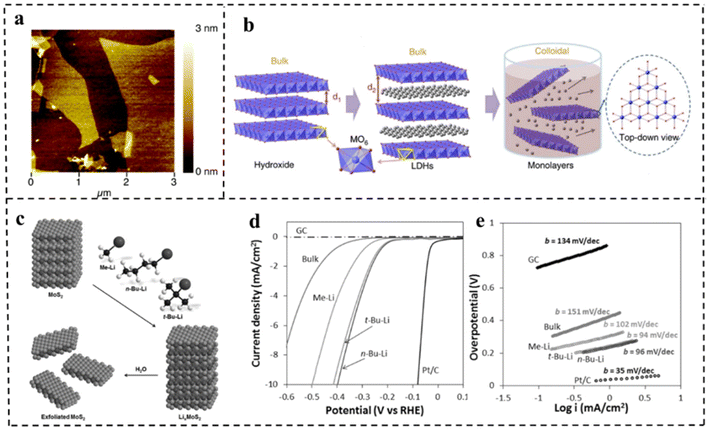 | ||
| Fig. 4 (a) AFM image of delaminated MgAl-LDH sheets. Reproduced with permission from ref. 74. Copyright 2005, American Chemical Society. (b) Schematic representation of LDH nanosheets' synthesis and structures. Reproduced with permission from ref. 75. Copyright 2014, Springer Nature. (c) Schematic representation of exfoliation of MoS2 with methyllithium, n-butyllithium and tert-butyllithium. (d) Polarization curves and (e) corresponding Tafel plots for MoS2 with different exfoliation media and other control materials. Reproduced with permission from ref. 76. Copyright 2015, Wiley-VCH. | ||
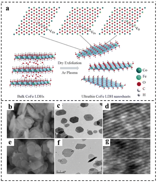 | ||
| Fig. 5 (a) Schematic representation of CoFe LDH nanosheets obtained by Ar plasma exfoliation. Scanning electron microscope (SEM), transmission electron microscope (TEM), and high resolution transmission electron microscope (HRTEM) images of (b–d) the bulk CoFe LDHs and (e–g) the ultrathin CoFe LDHs–Ar nanosheets. Reproduced with permission from ref. 80. Copyright 2017, Wiley-VCH. | ||
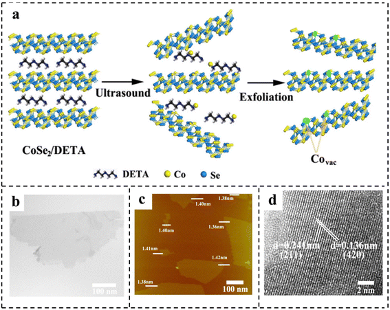 | ||
| Fig. 6 (a) Schematic of the formation of vacancies in CoSe2 ultrathin nanosheets. Characterization of CoSe2 ultrathin nanosheets: (b) TEM image; (c) AFM image; (d) HRTEM image. Reproduced with permission from ref. 85. Copyright 2014, American Chemical Society. | ||
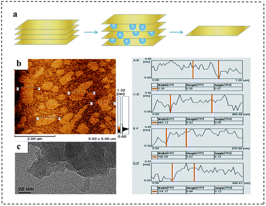 | ||
| Fig. 7 (a) Illustration of the synthetic strategy of monolayer g-C3N4 nanosheets. (b) AFM images and (c) TEM images of the as-prepared monolayer g-C3N4 nanosheets. The right panel shows the height and width information of different nanosheets from the AFM images. Reproduced with permission from ref. 89. Copyright 2013, Royal Society of Chemistry. | ||
Song et al.90 obtained MnDMS nanosheets from a flexible ligand 2,2-dimethylsuccinate and Mn ions. The MnDMS nanoparticles could be obtained by simple ultrasonication of a MnDMS crystal, which could then be exfoliated into ultrathin nanosheets by lithium-ion intercalation. Huang et al.91 developed an electro-chemical/chemical exfoliation strategy to prepare ultrathin 2D Co-MOF nanosheets as an efficient OER electrocatalyst. Chemical exfoliation is also generally suitable for stripping bulk TMDs with organolithium compounds such as butyllithium (BuLi),92,93 methyllithium (MeLi),94 or lithium borohydride (LiBH4)95 as intercalation reagents (Fig. 8a–e). In these studies, Jin et al.93 converted 2H–MoS2 multilayered semiconducting nanostructures into 1T-MoS2 polycrystalline nanosheets by soaking them in n-butyl lithium solution at room temperature for 6–48 hours (Fig. 8b). Due to the electron transfer of the embedded Li, the original triangular prismatic 2H–MoS2 structure was destroyed, which was conducive to the octahedral coordination of Mo atoms, thus achieving the transition to the 1T phase. Then, by reacting the embedded lithium with excess water to produce hydrogen, the nanostructures were stripped away, thereby separating the two-dimensional nanosheets.
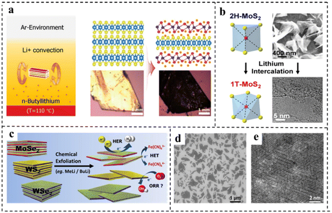 | ||
| Fig. 8 (a) Illustration of the synthetic strategy and structure of vertical hetero-phase MoTe2 (experimental setup for the Li+-intercalation into a MoTe2 single crystal, and the convectional flow of Li+ ions was described by two brown arrows in n-butyllithium solution). Reproduced with permission from ref. 92. Copyright 2019, Wiley-VCH. (b) Illustration of the synthetic strategy of 1T-MoS2. Reproduced with permission from ref. 93. Copyright 2013, American Chemical Society. (c) Illustration of the synthetic strategy of various chemically exfoliated TMDs (MoSe2, WS2, and WSe2). Reproduced with permission from ref. 94. Copyright 2014, American Chemical Society. (d) SEM image of chemically exfoliated MoS2 nanosheets deposited on SiO2. (e) HRTEM image of chemically exfoliated MoS2 with octahedral coordination (1T phase). Reproduced with permission from ref. 95. Copyright 2013, American Chemical Society. | ||
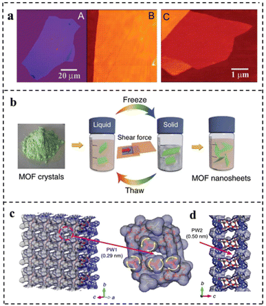 | ||
| Fig. 9 (a) Graphene films: (A) photograph (in normal white light) of a relatively large multilayer graphene flake with a thickness of ∼3 nm on top of an oxidized Si wafer. (B) AFM image of a 2 μm by 2 μm area of this flake near its edge. Colors: dark brown, SiO2 surface; orange, 3 nm height above the SiO2 surface. (C) AFM image of single-layer graphene. Colors: dark brown, SiO2 surface; brown-red (central area), 0.8 nm height; yellow-brown (bottom left), 1.2 nm; orange (top left), 2.5 nm. Notice the folded part of the film near the bottom, which exhibited a differential height of ∼0.4 nm. Reproduced with permission from ref. 23. Copyright 2004, The American Association for the Advancement of Science. (b) Schematic of freeze–thaw exfoliation of MAMS-1 crystals into dispersed nanosheets. (c) Tilted vertical view of the ab plane in the MAMS-1 monolayer featuring PW1 (amplified view of PW1 highlighted in magenta). (d) View along an axis of the MAMS-1 monolayer featuring PW2. Reproduced with permission from ref. 96. Copyright 2017, Springer Nature. | ||
In 2010, a monolayer and small amount of MoS2 were stripped on a SiO2/Si substrate. Using a micromechanical stripping method widely used for preparing graphene samples, large pieces of MoS2 were placed on a strip of tape, which was repeatedly folded and unfolded to separate single and multi-layer MoS2 films from the 2H–MoS2 bulk crystal and then pressed the tape onto a silicon substrate covered with a SiO2 layer. The measurements showed that exfoliation produced layers with a discrete number of these units. The measurements showed that exfoliation produced layers with a discrete number of these units. The AFM image showed that the thickness of monolayer MoS2 was 0.6–0.7 nm, which was consistent with the layer spacing of monolayer MoS2 (0.62 nm), and the films composed of MoS2 showed a wide distribution in heights due to the stacking of layers (Fig. 10a–c).97
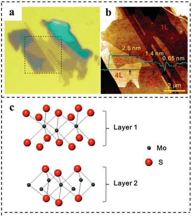 | ||
| Fig. 10 (a) Optical micrograph of thin MoS2 films deposited on the SiO2/Si substrate. (b) AFM height image was taken for the 8 × 8 μm2 area indicated by dotted lines in (a). The thickness of each layer is shown by the height profile (in green) taken along the blue line in the AFM image. (c) Schematic model of the MoS2 bilayer structure. Reproduced with permission from ref. 97. Copyright 2010, American Chemical Society. | ||
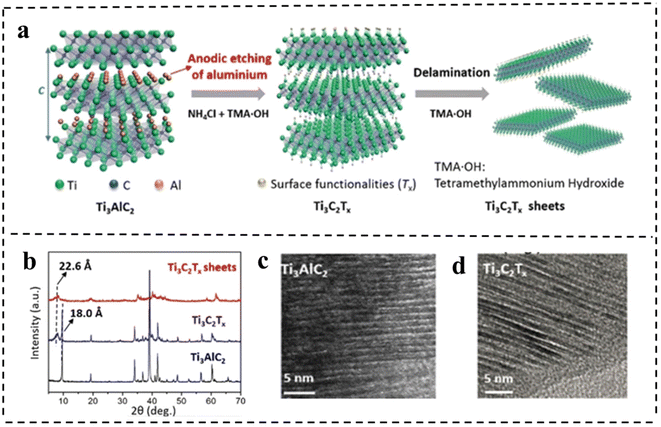 | ||
| Fig. 11 (a) Schematic of the etching and delamination process of bulk Ti3AlC2. (b) XRD patterns of Ti3AlC2 and Ti3C2Tx. HRTEM images of (c) Ti3AlC2 and (d) Ti3C2Tx, respectively. Reproduced with permission from ref. 101. Copyright 2018, Wiley-VCH. | ||
3.2 Bottom-up
Although top-down approaches facilitate the preparation of 2D nanomaterials with specific properties and provide low-cost products using direct methods, these approaches still have limitations for the practical application of 2D nanomaterials. These problems include formation of unstable nanosheets, inability to control the number of layers, limitation of layered materials, low yield of products, and frequent breakage and re-stacking of stripped nanosheets. Unlike the top-down approach, the bottom-up synthesis method enables the synthesis of different ultrathin nanosheets by controlling the growth direction or inhibiting the chemical synthesis of inter-layer interactions during the synthesis process. It has the advantages of high preparation yield, controllable thickness, large transverse size and good dispersion for the synthesized 2D nanomaterials. Common bottom-up synthesis methods include solvothermal synthesis, surfactant-assisted synthesis, chemical vapor deposition, inorganic–organic additive synthesis, etc.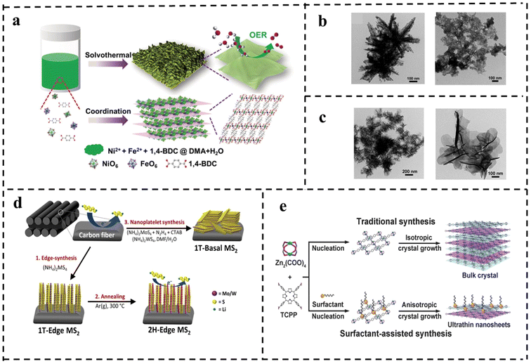 | ||
| Fig. 12 (a) Schematic of the synthetic process for the ultrathin metal–organic framework nanosheets and their utilization for the OER. TEM images of (b) with water as solvent only and with DMAC as reaction solvent only and (c) ultra-thin NiFe-MOF NSs. Reproduced with permission from ref. 107. Copyright 2019, Wiley-VCH. (d) Schematic of structured synthesis of TMDs (MS2, M = Mo/W) on carbon cloth. Reproduced with permission from ref. 108. Copyright 2019, Elsevier. (e) Schematic of the synthesis of Zn-TCPP. Reproduced with permission from ref. 109. Copyright 2015, Wiley-VCH. | ||
The solvothermal method has the advantages of being easy to operate (one-step synthesis) and easy to scale (gram-scale has been achieved in some cases), and is a no-addition process. However, it is only sometimes applicable to different situations, and direct solvothermal synthesis largely depends on the proper selection of solvents and reaction conditions.
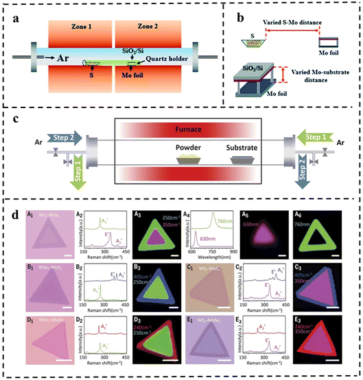 | ||
| Fig. 13 (a) The sketch of the CVD system for the growth of MoS2 flakes. (b) Schematic diagram of the varied distance between Mo foil and the S/growth substrate. Reproduced with permission from ref. 114. Copyright 2021, Royal Society of Chemistry. (c) Schematic diagram of the modified CVD system with a reversible Ar flow for the epitaxial growth of the lateral TMD heterostructures. (d) Optical microscopy images for the grown various 2D NSs with lateral heterostructures using the setup and their corresponding characterization. Reproduced with permission from ref. 115. Copyright 2017, The American Association for the Advancement of Science. | ||
The improved step-by-step CVD synthesis could fabricate multiple heterojunctions. In general, the lateral heterostructures of the two different TMD monolayers are fragile and may not survive the multi-step growth process. In 2017, Zhang et al.115 proposed a novel step-by-step synthesis strategy that successfully solved this problem. Various in-plane 2D TMD nanostructures were grown by reversing the gas flow direction. Firstly, monolayer TMD NSs were grown on a substrate by the CVD method. During the sequential growth process, the original long monolayer was placed downstream of the argon gas flow, which reversed the flow during the temperature change, thus cooling the existing monolayer TMD material and preventing undesirable thermal degradation from occurring. Also, the reverse argon flow suppressed uncontrolled nucleation prior to the sequential growth step (Fig. 13c). This effective CVD technique can produce WSe2–MoS2 and multiple heterojunctions (WS2–WSe2–MoS2 and WS2–MoSe2–WSe2, Fig. 13d).
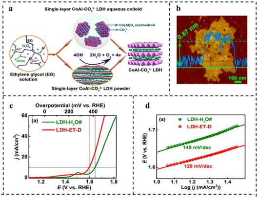 | ||
| Fig. 14 (a) Schematic diagram of synthesis of water-dispersible single-layer CoAl–CO32− LDH. (b) AFM image of single-layer CoAl–CO32− LDH. (c) Polarization curves in O2-saturated 1 M KOH at a scan rate of 0.5 mV s−1. (d) Tafel plots corresponding to (c). Reproduced with permission from ref. 116. Copyright 2017, American Chemical Society. | ||
4. Activation strategies
In this section, we will focus on the recent development of 2D bifunctional nanocatalysts with both HER and OER activity in the field of full water splitting. And we will discuss and summarize some typical strategies for enhancing bifunctional activities, including doping, nanocomposite construction, interface formation, defect engineering, morphology modulation and so on. The structure–activity relationships will also be discussed with the aim of providing guidance in designing novel 2D bifunctional electrocatalysts. The recent research advancements in 2D bifunctional nanocatalysts for full water splitting are comprehensively summarized in Table 1.| Catalyst | Synthesis method | Electrolyte | η 10 | Tafel slope | Ref. | ||||
|---|---|---|---|---|---|---|---|---|---|
| HER | OER | Overall WE | HER | OER | |||||
| Activation strategies | NiVRu-LDH | One-pot hydrothermal | 1.0 M KOH | 12 mV | 190 mV | 1.42 V | 40 mV dec−1 | 83 mV dec−1 | 118 |
| NiVIr-LDH | 47 mV | 180 mV | 107 mV dec−1 | 38 mV dec−1 | |||||
| Ni–MoSe2@Ti2NTx | Hydrothermal | 1.0 M KOH | 92 mV | 270 mv (η50) | 1.59 V | 79.7 mV dec−1 | 81.1 mV dec−1 | 119 | |
| Nanocomposite construction | NiFe LDH-NS@DG10 | Stripping | 1.0 M KOH | 300 mV | 210 mV | 1.5 V | 110 mV dec−1 | 52 mV dec−1 | 125 |
| Ni3S2/VG@NiCo LDHs | Electrodeposition | 1.0 M KOH | 120 mV | 320 mV (η100) | 1.66 V | 87 mV dec−1 | 97 mV dec−1 | 126 | |
| CoFe@NiFe/NF | Hydrothermal electrodeposition | 1.0 M KOH | 240 mV | 190 mV | 1.59 V | 88.88 mV dec−1 | 45.7 mV dec−1 | 127 | |
| Ir/g-C3N4/NG | Solvothermal | 1.0 M KOH | 22 mV | 300 mV | 1.56 V | 22 mV dec−1 | 72.8 mV dec−1 | 128 | |
| g-C3N4/CeO2/Fe3O4 | Coprecipitation | 1.0 M KOH | 310 mV | 400 mV | 1.94 V | 102 mV dec−1 | 74 mV dec−1 | 129 | |
| CoP/Ti3C2 MXene | In situ phosphorylation | 1.0 M KOH | 102 mV | 280 mV | 1.58 V | 68.7 mV dec−1 | 95.4 mV dec−1 | 131 | |
| NFPS@MXene | Self-assemble | 1.0 M KOH | 196 mV | 282 mV | 1.65 V | 114 mV dec−1 | 36.5 mV dec−1 | 132 | |
| Ni3S2@MoS2/FeOOH | Electrodeposited | 1.0 M KOH | 95 mV | 234 mV | 1.57 V | 85 mV dec−1 | 49 mV dec−1 | 134 | |
| LSC/K–MoSe2 | Sol–gel molten-metal-assisted | 1.0 M KOH | 128 mV | 230 mV | 1.59 V | 45 mV dec−1 | 79 mV dec−1 | 135 | |
| Interface formation | ZIF/Ni–B@NF | Room-temperature boronization | 1.0 M KOH | 67 mV | 234 mV | 1.54 V | 108 mV dec−1 | 76 mV dec−1 | 140 |
| MoSe2–Cu2S (NHSs) | Defect passivated colloidal | 1.0 M KOH | 350 mV | 264 mV | — | 110 mV dec−1 | 63 mV dec−1 | 141 | |
| Ni0.85Se–MoSe2 | Solvothermal hydrothermal | 1.0 M KOH | 108 mV | 380 mV | 1.70 V | 77 mV dec−1 | — | 142 | |
| Ni0.75Se | Solvothermal hydrothermal | 1.0 M KOH | 221 mV | 340 mV | 172 mV dec−1 | — | |||
| Defect engineering | P–V–NiFe LDH NSA | Cation doping plasma reduction | 1.0 M KOH | 19 mV | 29 5 mV (η100) | 1.43 V | 38 mv dec−1 | 56 mV dec−1 | 147 |
| MoS2/NiS2 | Hydrothermal | 1.0 M KOH | 62 mV | 278 mV | 1.59 V | 50.1 mV dec−1 | 91.7 mv dec−1 | 148 | |
| Morphology modulation | CoSe2 spheres | Hydrothermal | 1.0 M KOH | — | 325 mV | — | — | 80 mV dec−1 | 152 |
| 0.5 M H2SO4 | 167 mV | — | — | 38 mV dec−1 | — | ||||
| NiFe-MOF | One-step chemical bath deposition | 0.1 M KOH | 134 mV | 240 mV | 1.55 V | — | 34 mV dec−1 | 153 | |
| NiFe (dobpdc) | Hydrothermal | 1.0 M KOH | 113 mV | 207 mV | 1.59 V | 69 mV dec−1 | 36 mV dec−1 | 154 | |
| Cu@NiFeLDH | Electrodeposition | 1.0 M KOH | 116 mV | 199 mV | 1.54 V | 58.9 mV dec−1 | 27.8 mV dec−1 | 155 | |
4.1 Doping
Doping can tailor the band structure, valence state of the active site, charge redistribution, and the adsorption and desorption behaviors of reactants, intermediates and products, which facilitates H2 and O2 evolution.117Xing et al.118 synthesized NiV-LDH, NiVRu-LDH, and NiVIr-LDH by a simple one-step hydrothermal method and found that doping Ru or Ir in self-supported NiV-LDH could induce the V vacancy which was verified by Raman and X-ray absorption fine structure (XAFS) as shown in Fig. 15a. DFT calculations showed that Ru and Ir doping in NiV-LDH could optimize the adsorption energy of intermediates during the HER process, while accelerating the OER kinetic process as shown in Fig. 15b–e. Therefore, the NiVIr-LDH‖NiVRu-LDH electrolyzer showed excellent catalytic activity which could provide a current density of 10 mA cm−2 with only 1.42 V, much smaller than that of RuO2‖Pt/C.
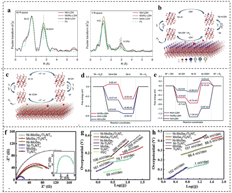 | ||
| Fig. 15 (a) Ni and d V K-edge extended XANES oscillation functions k3χ (k). (b) The atomic model of NiVRu-LDH and the proposed HER pathway. (c) The atomic model of NiVIr-LDH and the proposed OER pathway. (d) The free energy diagram of the HER and (e) OER on the NiV-LDH, NiVRu-LDH, and NiVIr-LDH catalysts. Reproduced with permission from ref. 118. Copyright 2019, Springer Nature. (f) The Nyquist plots and Tafel plots of HER performance (g) and OER performance (h) of Ni–MoSe2@Ti2NTx and other control materials. Reproduced with permission from ref. 119. Copyright 2020, Elsevier. | ||
Doping transition metals can also improve the electrical conductivity and stability of catalysts. For example, Zong et al.119 synthesized Ni doped MoSe2@Ti2NTx. The study revealed that Ni doped MoSe2 had improved HER properties as Ni doping generated numerous hydrolysis sites and decreased the energy barrier required for overall water splitting. The replacement of Ni atoms with Mo in MoSe2 also produced a catalyst with semi-conducting properties, thus enhancing its electrical conductivity (Fig. 15f). For the HER, Ni–MoSe2@Ti2NTx showed an overpotential of 92 mV at 10 mA cm−2 and a Tafel slope of only 79.7 mV dec−1as compared to MoSe2@Ti2NTx (η10: 139 mV and Tafel slope: 118 mV dec−1), revealing that Ni doping profoundly elevated HER activity (Fig. 15g). For the OER, Ni–MoSe2@Ti2NTx revealed an η50 of 270 mV and a Tafel slope of 81.1 mV dec−1 as compared to MoSe2@Ti2NTx (η50: 328 mV and Tafel slope: 96.4 mV dec−1) (Fig. 15h). Due to the Ni doping improved HER and OER performance in alkaline media, Ni–MoSe2@Ti2NTx was utilized as both the anode and the cathode, which exhibited a small voltage of 1.59 V to afford a current density of 10 mA cm−2.
Although doping is one of the good strategies to improve the catalytic performance of 2D catalysts, there are still some limitations: the site and density of doping cannot be controlled precisely through currently developed synthesis techniques, which results in difficulty in fine-tuning the activity of electrocatalysts.
4.2 Nanocomposite construction
Constructing a 2D composite catalyst can enhance the water electrolysis efficiency of bifunctional catalysts.120,121 The heterostructures usually comprise two or more different components, possibly integrating the merits and overcoming the disadvantages of the individual ones.122,123 Hybridization of catalytically active components with highly conductive substrate materials to form composites is a widely used method that can synergistically achieve optimized electronic structures, abundant active sites, and improved operational stability,124 and the selection of materials that can have a synergistic effect with existing materials is the difficulty of this strategy. This section summarizes the research advances in 2D materials including LDH, g-C3N4, MXene and TMD hybridizing with other components to construct bifunctional catalysts for overall water splitting in recent years.2D carbonaceous materials (e.g., graphene) with a large surface area and outstanding electrical conductivity have been considered ideal substrates for anchoring electrocatalysts to achieve enhanced activity. Yao's group125 reported a highly efficient bifunctional catalyst based on strongly coupled stripped NiFe-LDH nanosheets and defective graphene (DG) (Fig. 16a). The catalyst showed high electrocatalytic activity for the OER, with an η10 of 210 mV and a Tafel slope of 52 mV dec−1 under alkaline conditions. The excellent OER and HER activities of the prepared NiFe LDH-NS@DG10 catalysts were due to the more efficient anchoring sites on DG brought about by the defects, which resulted in the direct and strong coupling of transition metal atoms (Ni and Fe) on 2D NiFe-LDH nanolayers. DFT calculations demonstrated that the separation and redistribution of electrons and holes on DG and NiFe LDH were achieved through the combination of DG and NiFe LDH (Fig. 16b and c). The high density of electrons on DG elevated the HER, while the high density of holes on NiFe LDH enhanced the OER. The Han, s group126 reported a bifunctional electrocatalyst consisting of Ni3S2 as the template, vertical graphene (VG) as the bridging material, and NiCo-LDH nanosheets as the active catalyst, as shown in Fig. 16d–f. It is found that the VG bridging between NiCo-LDH and Ni3S2 enabled fast charge-transfer and a high density of active sites, resulting in improved electrical conductivity, intrinsic activity, and electrochemical stability. The hybrid Ni3S2/VG@NiCo LDH catalyst exhibited excellent activity in alkaline solution for both the OER and the HER. In addition, the hybrid catalyst possessed superior stability with 99% retention of voltage upon a continued current density of 10 mA cm−2 for over 24 h. Similarly, Shi and coworkers127 prepared a novel CoFe-LDH@NiFe-LDH core–shell architecture on NF through a facile hydrothermal and electrodeposition method. The formed CoFe-LDH@NiFe-LDH core–shell architectures featured a 3D interconnected porous structure, which provided abundantly accessible active sites and contact areas with electrolytes. In addition, the strong electronic interaction between CoFe-LDH and NiFe-LDH not only promoted fast charge transfer at the interface, but also synergistically optimized the binding energies of the reaction intermediates, thus accelerating the reaction kinetics and enhancing the electrocatalytic efficiency. The resulting CoFe@NiFe/NF electrode architectures exhibited excellent activities and stabilities for the OER and HER. Furthermore, an efficient and stable alkaline electrolyzer using CoFe@NiFe/NF as both the cathode and anode achieved a voltage of 1.59 V at 10 mA cm−2.
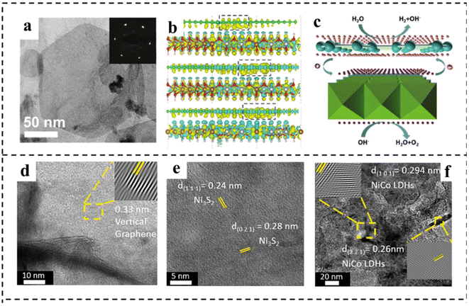 | ||
| Fig. 16 (a) TEM image of typical exfoliated LDH-NS anchored on DG with the corresponding selected area diffraction pattern (inset). (b) The side views of the3D charge density difference plot for the interfaces between defective graphene sheets (DG-5, DG-585, or DG-5775). Yellow and cyan isosurfaces represent charge accumulation, and green, brown, silver, and red balls represent C, Fe, Ni, and O atoms, respectively. (c) Schematic illustration of NiFe LDH-NS@DG10 for overall water splitting. The pink and purple spheres represent electrons and holes, respectively. Reproduced with permission from ref. 125. Copyright 2017, Wiley-VCH. (d–f) HRTEM images of VG, Ni3S2, and NiCo LDHs. Reproduced with permission from ref. 126. Copyright 2021, Elsevier. | ||
The construction of a composite can also solve the problems of poor conductivity and the lack of redox sites of graphitic carbon nitride (g-C3N4). Jiang et al.128 reported nitrogen-doped graphene (NG) chemically coupled with g-C3N4 to form C3N4/NG layers composited with monodispersed Ir nanoparticles. The C3N4/NG layers facilitated the kinetics of overall electrochemical water splitting: firstly, due to the presence of pyridine N in g-C3N4, the nearby C atoms with SP2 hybrid has a high positive charge density, which is conducive to the adsorption of the reactant and the charge transfer between the reaction species and the catalyst surface, thus improving the OER performance. Additionally, C3N4/NG delivered high HER performance owing to its moderate adsorption–desorption ability for hydrogen, thus accelerating the kinetics of full water splitting. Moreover, g-C3N4 was helpful to the dispersion of active materials without aggregation, thereby exposing the active sites. Rashid et al.129 reported the first ternary composite based on g-C3N4, which consisted of g-C3N4, CeO2 and Fe3O4, showing an excellent and durable bifunctional catalytic activity for the OER and HER in the alkaline medium owing to the synergetic effects between the three ingredients.
MXene has high conductivity, which can afford the rapid transfer of electrons, and as a result it is often used as a highly conductive substrate to improve the activity of catalysts.130 For example, Yan and his group131 reported a general approach to synthesize CoP/Ti3C2 MXene on Ti3C2 MXene nanosheets. In the CoP/Ti3C2 MXene hybrid, Ti3C2 MXene as a highly conductive substrate not only facilitated rapid electron transfer, but also prevented the aggregation of CoP nanoarrays. Meanwhile, CoP nanoarrays could prevent restacking of MXene nanosheets. Especially, the strong interactions between CoP and Ti3C2 MXene endowed the CoP/Ti3C2 MXene composite with exceptional catalytic activities and stabilities toward the HER at all pH values. Meanwhile, CoP/Ti3C2 MXene also exhibited superior OER performance in alkaline electrolyte. The CoP/Ti3C2 MXene even outperformed the commercial Pt/C‖IrO2 couple for overall water splitting under alkaline conditions. Du et al.132 synthesized a novel NixFe1−x PS3/MXene (NFPS/MXene) hybrid through a facile self-assembly process of LDH on a MXene surface, followed by a low temperature in situ solid phase reaction. The final NFPS showed nano-mosaic shapes instead of the original TM-LDHS nanosheets, which had a unique electronic structure and extremely high electrochemically active surface area, leading to excellent overall water splitting activity in 1 M KOH.
MoS2 shows favorable activity for the HER in acidic electrolytes due to the near-optimal hydrogen adsorption free energy. However, the HER kinetics of MoS2 under alkaline conditions are sluggish due to the inferior ability for water dissociation.133 FeOOH shows much stronger adsorption of hydroxyl species, enabling it to be effective for water dissociation. Unfortunately, the OER activity of FeOOH is much inferior due to its strong interaction with hydroxyl species. Xu et al.134 found that coupling FeOOH with MoS2 could not only promote the alkaline HER activity of MoS2 by accelerating water dissociation, but also enhance the OER activity of FeOOH through the electronic modulation by MoS2 (Fig. 17a). This one-stone-two-birds effect enabled the hybrid MoS2/FeOOH to show outstanding HER and OER performance. The MoS2/FeOOH was further coupled with 3D Ni3S2 nanowires to fabricate the Ni3S2@MoS2/FeOOH. The morphological characterization indicated that FeOOH nanosheets were intimately coupled with MoS2 nanosheets (Fig. 17b). XPS analyses revealed electron transfer from Fe atoms to Mo atoms (Fig. 17c and d). The Mo sites with a lower state in MoS2 had higher HER activity, and the Fe sites with a higher state in FeOOH had higher OER activity. Such electronic modulation of Fe and Mo centers in Ni3S2@MoS2/FeOOH hybrids was beneficial to improving their HER and OER activities. Ni3S2@MoS2/FeOOH as an OER catalyst showed the lowest Tafel slope of 49 mV dec−1, lower than that of Ni3S2/FeOOH (56 mV dec−1) and Ni3S2@MoS2 (114.0 mV dec−1). Meanwhile, the catalyst exhibited a very low overpotential of 282 mV at a high current density of 100 mA cm−2. Impressively, as an HER catalyst, Ni3S2@MoS2/FeOOH could output a current density of 100 mA cm−2 at a low overpotential of 177 mV, showing excellent electrocatalytic HER performance. Furthermore, as a bifunctional electrocatalyst, the electrocatalyst required only a small battery voltage of 1.57 V at 10 mA cm−2. Han et al.135 developed a composite catalyst consisting of perovskite oxide (La0.5Sr0.5CoO3−δ, LSC) and potassium ionically bonded molybdenum diselenide (K–MoSe2) as a bifunctional catalyst for integral hydrolyzation (Fig. 17e). It is found that the LSC/K–MoSe2 system had the characteristics of multi-direction charge transfer phenomena, including bidirectional charge transfer from K to MoSe2 and from LSC to MoSe2 (Fig. 17f), which endowed MoSe2 with an electron-rich surface and increased electrical conductivity to improve the HER kinetics (Fig. 17g and h). Besides, the improvement of the electrophilicity of LSC improved the adsorption capacity of oxygen producing intermediates on the catalyst surface, thus improving the performance of the OER (Fig. 17i). Furthermore, LSC/K–MoSe2 exhibited remarkable chronopotentiometry stability over 2500 h at a high current density of 100 mA cm−2.
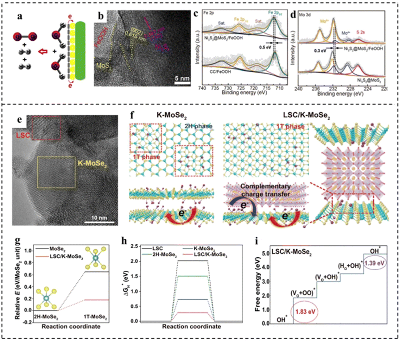 | ||
| Fig. 17 (a) Schematic diagram for the overall water splitting mechanism of Ni3S2@MoS2/FeOOH. (b) HRTEM image of Ni3S2@MoS2/FeOOH. (c) Fe 2p XPS spectra of Ni3S2@MoS2/FeOOH and FeOOH on carbon cloth (FeOOH/CC). (d) Mo 3d XPS spectra of Ni3S2@MoS2/FeOOH and Ni3S2@MoS2. Reproduced with permission from ref. 134. Copyright 2019, Elsevier. (e) HRTEM image of LSC/K–MoSe2. (f) Schematic of the atomic structure and charge transfer effect for K–MoSe2 and LSC/K–MoSe2. Complementary charge transfer in LSC/K–MoSe2 can modulate the electronic structure of MoSe2, increasing the 1T-MoSe2 ratio in the heterostructure. (g) Relative energies of 1T-MoSe2 in the monolayer structure (black line) and LSC/K–MoSe2 heterostructure (red line) compared to the energy of the 2H–MoSe2 monolayer. (h) Free energy diagrams for the HER for LSC, 2H–MoSe2, K–MoSe2, and LSC/K–MoSe2. (i) Free energy diagrams for the OER for LSC/K–MoSe2. Reproduced with permission from ref. 135. Copyright 2021, Springer Nature. | ||
4.3 Interface formation
Interface engineering can create new active sites and promote electron transfer, thus boosting the efficiency of water splitting.136,137 Moreover, the generated synergetic effects between different interfaces tailor the electronic structures of catalysts and the modulated electronic structure in turn influences the overall performance in electrocatalysis. Owing to the ultrathin properties of 2D components, most atoms in 2D layers can participate in the interface structure, which may lead to more pronounced interface effects on the modulation of electronic structures than in the ontology.138,139 For example, Wu constructed a rich crystalline-amorphous boundary into ultrathin Ni-ZIF/Ni–B nanosheets.140 DFT calculations indicated that the crystalline-amorphous interface not only reduced the energy barrier for the formation of *OH, but also reduced the reaction free energy from *O to *OOH. Besides, an optimal ΔGH* that was closer to zero implied its higher catalytic HER activity (Fig. 18a and b). Benefiting from the interface engineering, the Ni-ZIF/Ni–B nanosheets required an η10 of 67 mV for the HER and an η10 of 234 mV for the OER. Furthermore Ni-ZIF/Ni–B@NF as a bifunctional electrocatalyst for overall water splitting achieved an η10 of 1.54 V. Sapra et al.141 used interfacial engineering of the basal planes of MoSe2 nanosheets (NSs) with Cu2S nanocrystals (NCs) to obviously promote the water splitting rate under alkaline conditions (Fig. 18c and d). In their work, the interface between the MoSe2 NSs and Cu2S NCs increased the number of OER active sites, as shown in Fig. 18e and f. The type-II alignment of nanoheterostructures (NHSs) formed an in-built potential at the interfaces, which helped to facilitate interfacial charge transfer at the junctions of two constituents. DFT calculations revealed (Fig. 18g and h) that due to the presence of type II NHSs, Cu2S NCs formed a built-in electric field at the junction, making them more electrophilic. This made the catalytic active site of NHSs more favorable for surface adsorption and conversion. The internal electric field at the interface significantly reduced the energy barrier for the formation of OH*, O*, OOH* and other intermediates, thus promoting the OER. Due to the increased number of active sites and the modulation of the electronic structure, MoSe2–Cu2S NHSs exhibited higher OER activity with an η10 of 264 mV. Also, the built-in electric field also greatly promoted the HER activity of MoSe2–Cu2S NHSs owing to the reduction of the kinetic energy barrier. Mahalingam and coworkers142 introduced Ni0.75Se nanoparticles into MoSe2 to construct a Ni0.85Se/MoSe2 interface, which served as an active site for water splitting. The synthesized interfacial structure was composed of interlinked Ni0.85Se nanoparticles and MoSe2 thin slices with abundant heterojunctions. As shown in Fig. 18i–l, SEM and TEM revealed distinguishable interfaces (boundaries) between Ni0.85Se particles and MoSe2 flakes. Electrochemical investigations showed that the alkaline HER activity of the Ni0.85Se/MoSe2 interface structure was significantly increased, which was attributed to the efficient hydrolysis dissociation process on the Ni0.85Se promoter in the interface structure and the exposure of more MoSe2 catalytically active sites (edges). In addition, the prepared Ni0.85Se/MoSe2 showed high OER activity. An alkaline electrolysis cell was constructed with Ni0.85Se/MoSe2 and Ni0.75Se as the cathode and anode, showing a voltage of 1.7 V at 10 mA cm−2.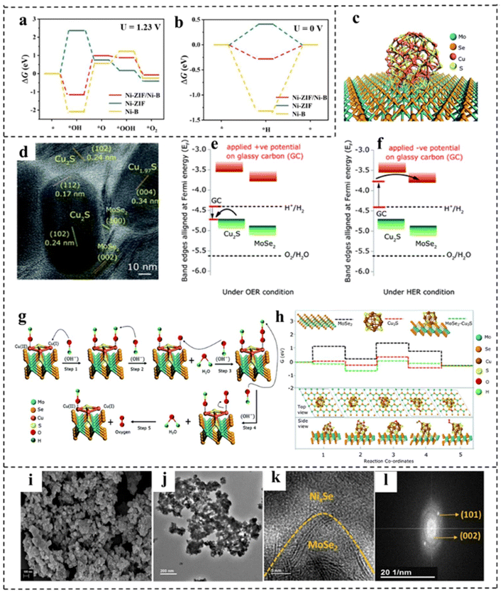 | ||
| Fig. 18 (a) The calculated free–energy diagram of the OER and (b) the HER of Ni-ZIF/Ni–B and other control materials. Reproduced with permission from ref. 140. Copyright 2020, Wiley-VCH. (c) Schematic illustration of MoSe2–Cu2S NHSs. (d) HRTEM image of MoSe2–Cu2S NHSs. Schematic illustration of the energy band alignment of MoSe2–Cu2S NHSs in (e) the OER via Cu2S and (f) the HER via MoSe2. (g) Schematic illustration of the mechanism of the OER. (h) Free energy profiles of the reactants, intermediates and products of the OER for MoSe2 NSs, Cu2S NCs and MoSe2–Cu2S NHSs. Reproduced with permission from ref. 141. Copyright 2021, Royal Society of Chemistry. (i–k) SEM, TEM, and HRTEM images, and (l) fast Fourier transformation of the Ni0.85Se–MoSe2 interfacial structure. Reproduced with permission from ref. 142. Copyright 2021, American Chemical Society. | ||
Interfacial engineering can be used to enhance the performance of overall water splitting. However, the heterogeneous interface and its microenvironment are complex, which makes the study of the catalytic reaction mechanism difficult. Besides, because of the simplification and idealization of the constructed model in theoretical calculations, there is still a gap between the heterogeneous interface model and the actual catalyst's interface. This makes it difficult for theoretical calculations to accurately reveal the real catalytic mechanism.
4.4 Defect engineering
Introducing defects into catalysts is another important strategy to enhance intrinsic activity. With the introduction of defect structures, the electronic configurations of catalyst sites are effectively tuned to facilitate the formation and transformation of intermediate states, thereby promoting specific electrochemical reactions. In most cases, defects are generally regarded as active sites for electrocatalytic processes due to the regulation of localized electronic and surface configurations.143,144 According to their sizes, defects in catalytic materials can be mainly divided into four types, including 0 D point defects, 1D line defects, 2D plane defects and 3D volume defects. Point defects can be further divided into three types: vacancy defects, impurity doped defects and metal defect coordination structures.145 First, defect engineering can provide more active sites for electrocatalysts, thus directly refining their electrocatalytic activity. Second, the rational construction of composites can form a large number of defective structures, which can effectively adjust the electronic structure and promote electron transfer, thus improving the efficiency of overall water separation. Third, catalytically active substances can be anchored on defective carriers, which can directly maximize the exposure of active substances and improve the charge transfer between catalytically active substances.At present, various strategies for defect construction have been used in 2D bifunctional electrocatalysts, such as high temperature reduction and plasma treatment.146 For example, Yu et al.147 synthesized a P–V–NiFe LDH nanosheet array (NSA) with multiple vacancies through a cation doping combined with plasma reduction strategy. As a bifunctional electrocatalyst, the P–V–NiFe LDH NSA shows a small η10 of 200 mV with significant stability for 1000 h. The authors discussed in detail the role of vacancy defects through structural analysis and theoretical simulation. As shown in Fig. 19a–c, the surface of NiFe LDH became rough after introducing defects. Meanwhile, DFT calculations revealed that V doping, oxygen vacancies (Ov) and Ni vacancies (Niv) could optimize the hydrogen adsorption (Fig. 19e and g) and increase the conductivity (Fig. 19f, h and i). In addition, Ov and Niv were favorable for H2O adsorption and dissociation in the HER, and the V-doping and Ov efficiently reduced the energy barrier for the formation of O* in the OER (Fig. 19d).
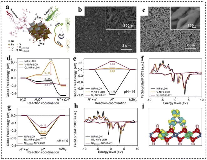 | ||
| Fig. 19 (a) Schematic illustration of the reaction mechanism of the P–V–NiFe LDH NSA. SEM images of (b) the NiFe LDH NSA and (c) the P–V–NiFe LDH NSA. The diagram of calculated adsorption free energy on the NiFe LDH (100) plane (d and e) and (001) plane (g) for the Volmer step (d) and Tafel step (e and g). The calculated projected densities of states of the Fe 3d orbital on the NiFe LDH (100) plane (f) and (001) plane (h). (i) The differential charge density contour plot after supporting Ni clusters on the NiFe LDH (001) plane. The cyan and yellow colors indicate the decrease and increase in the electron density, respectively. The 3D isosurface value is set as 0.007 e Å−3. Blue balls: Ni atoms; green balls: Fe atoms; red balls: O atoms; pink balls: H atoms. Reproduced with permission from ref. 147. Copyright 2020, Elsevier. | ||
Besides, the rational construction of composites can lead to the formation of defective structures. For example, Qi et al.148 prepared defect-rich MoS2/NiS2 nanosheets by annealing Ni–Mo precursors with sublimated sulfur in an Ar atmosphere (Fig. 20a). Fig. 20b–e demonstrate that MoS2/NiS2 had numerous defects and interfaces, providing more catalytic sites for electrocatalytic reactions. The mismatch between MoS2 and NiS2 created a distinct heterointerface that could induce abundant defects and disordered structures. Raman spectroscopy (Fig. 20f) further indicated the existence of abundant low-coordination Mo–S edge sites in MoS2/NiS2, while XPS demonstrated the existence of sulfur defects (Fig. 20g). This structure facilitated the generation of electrons and accelerated the electrocatalytic process, thereby improving the activities of the HER and OER. As a result, the optimized MoS2/NiS2 nanosheets showed a low voltage of 1.59 V at 10 mA cm−2 (Fig. 20h).
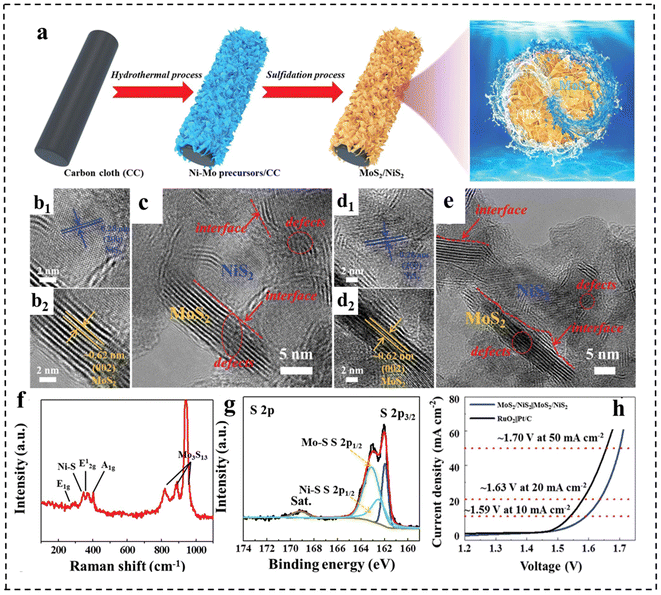 | ||
| Fig. 20 (a) Schematic illustration for the formation of defect-rich heterogeneous MoS2/NiS2 nanosheets. (b–e) HRTEM images of MoS2/NiS2 nanosheets. (f) Raman spectrum of MoS2/NiS2 nanosheets. (g) High-resolution XPS profiles of S 2p in MoS2/NiS2 nanosheets. (h) Polarization curves of optimal MoS2/NiS2 nanosheets and RuO2‖Pt/C for overall water splitting. Reproduced with permission from ref. 148. Copyright 2019, Wiley-VCH. | ||
Despite great advances, the reported strategies used to prepare defective catalysts, such as chemical etching and plasma etching, still present significant challenges in controlling site-specific defect construction and precisely controlling defect concentration.149 In addition, the most frequently reported defect-based materials rarely meet the practical needs of industrial production. Therefore, further research and development of methods for large-scale preparation of defect catalysts are necessary. Meanwhile, some defects are unstable, making the catalyst prone to failure during the catalytic process. Therefore, the stabilization of defects is also a concern of defect engineering. Whether stable defect structures can be maintained or reconstituted during the actual catalytic process needs to be further investigated. Besides, the quantification and precise control of defects are a challenge.
4.5 Morphology modulation
Morphological engineering of 2D nanomaterials as bifunctional electrocatalysts for full water splitting plays an important role in achieving excellent electrocatalytic performance, because it is closely related to the physical specific surface area, the number of exposed active centers for catalytic reactions, and the mass transfer during electrochemical reactions. Generally, morphological engineering is not as effective as other means of increasing the intrinsic activity of the catalyst. In this section, we present the rational design and effects of morphological engineering with typical examples.150,151 For example, Li et al.152 reported a simple and controllable strategy to prepare CoSe2 with different shapes. By adjusting the additional amount of NH4F, CoSe2 samples (spherical, linear and rod-like) were successfully synthesized (Fig. 21a–c). Among them, the CoSe2 microspheres were revealed to have a regular sea urchin shape and hollow structure, resulting in a large specific surface area and a large number of channels to promote mass transfer efficiency. Therefore, the CoSe2 sphere electrocatalyst showed excellent catalytic performance for the OER and HER under alkaline and acidic conditions, respectively (e.g., an η10 of 325 mV and a Tafel slope of 80 mV dec−1 for the OER in alkaline media and an η10 of 167 mV and a Tafel slope of 38 mV dec−1 for the HER in acidic media, respectively).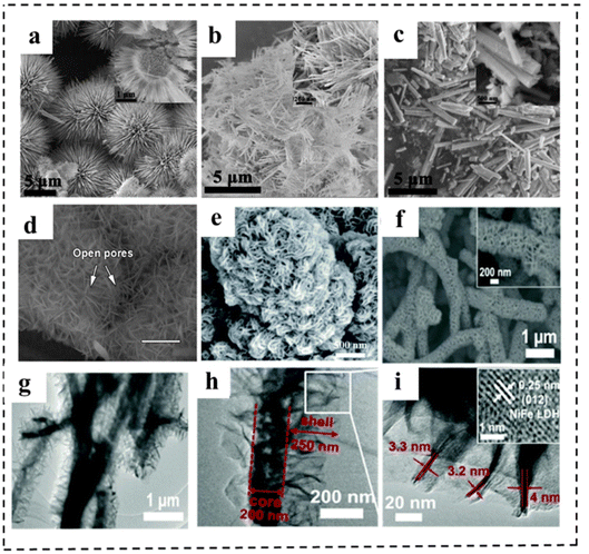 | ||
| Fig. 21 (a-c) SEM images of CoSe2 spheres, wires and rods. Reproduced with permission from ref. 152. Copyright 2019, Elsevier. (d) SEM image (scale bars are 300 mm) of NiFe-MOF/NF. Reproduced with permission from ref. 153. Copyright 2017, Springer Nature. (e) SEM images of NiFe (dobpdc). Reproduced with permission from ref. 154. Copyright 2020, Royal Society of Chemistry. (f) SEM images of Cu@NiFe LDH at high magnification. (g–i) TEM images of Cu@NiFe LDH. (j) Detailed image of the squared part in the image of Cu@NiFe LDH to show the lattice fringe (inset). Reproduced with permission from ref. 155. Copyright 2017, Royal Society of Chemistry. | ||
Morphological regulation strategies can also be used to ameliorate the catalytic performance of MOFs. The small pore size is one of the major challenges in using MOFs for electrocatalysis, which inhibits the effective mass transport of electrolytes to active centers and diffusion of products, resulting in hindered electrocatalyst performance. This is especially a problem in water electrolysis because the electrode products are O2 and H2 gases, which have the potential to cover the active sites of MOFs and inhibit ions' transport. To solve this issue, increasing the pore size of the MOF is a good solution. Zhao et al.153 prepared a MOF with different hierarchical-scale porosities (several-hundred-micrometre macropores, tens-of-nanometre open pores, several-nanometre mesopores and intrinsic microporosity). The extra-large macropores of nickel foam could facilitate the mass transport of electrolytes and gaseous products, while the open pores between vertically aligned nanosheets, and small mesopores and micropores of the MOF provided enormous, highly accessible active sites and short ion diffusion pathways (Fig. 21d). Thus, the resulting NiFe-MOF catalyst exhibited excellent activities and stabilities for the OER (η10: 240 mV) and HER (η10: 134 mV). The electrolytic cell was demonstrated to show excellent catalytic activity, delivering a voltage of 1.55 V at 10 mA cm−2 in 0.1 M KOH. Similarly, Lin et al.154 synthesized NiFe (dobpdc) by utilizing a longer organic linker (H4dobpdc). The NiFe (dobpdc) had a yarn-ball like structure assembled from 2D nanosheet subunits, and it possessed a high surface area and large pore size (Fig. 21e). This allowed adequate contact with H2O and enlarged the electrochemically active surface area, resulting in an accelerated water splitting reaction. This bifunctional NiFe (dobpdc) MOF electrocatalyst exhibited low overpotentials for the OER and HER, respectively. Moreover, DFT calculations revealed that the longer ligand (dobpdc4) had the ability of extracting and releasing charges during the steps of (* → OH*) and (OH* → O*), respectively.
Besides, 3D core–shell nanoarchitectures grown on conductive substrates are of great interest due to their large surface areas, efficient electron transfer, and intimate access to the electrolyte. For example, Yu et al.155 fabricated a 3D catalyst with a core–shell nanostructure, in which few-layer NiFe LDH nanosheets uniformly and vertically grew on Cu nanowire (NW) cores supported on Cu foam (Fig. 21f). The TEM image in Fig. 21g–i showed that the nanosheets were interconnected with each other, forming a highly porous surface morphology, which offered many channels for electrolyte diffusion and gaseous product release. Also, such a 3D nanostructure facilitated efficient electron transfer from the inner metallic Cu NWs to the outer shell of the NiFe LDH layer. Thus, the Cu@NiFe LDH exhibited outstanding OER as well as HER performance in alkaline medium. Using them as bifunctional catalysts for overall water splitting, a voltage of 1.54 V at 10 mA cm−2 was achieved with excellent durability, which was much better than the benchmark of IrO2(+)‖Pt(−) electrodes.
5. Conclusion and outlook
Electrolysis of water is an important technology for green hydrogen production facing energy and environmental crisis. In the past decades, great efforts and breakthroughs have been made in the design and optimization of bifunctional electrocatalysts. This paper systematically reviews the classification, controlled synthesis and formation mechanisms of 2D nanomaterials including graphitized carbon nitride, layered double hydroxide, transition metal dichalcogenide, transition metal carbon/nitride and 2D metal–organic framework compounds. The strategies for tuning the catalytic activity of 2D bifunctional electrocatalysts (doping, defect engineering, nanocomposite construction, interface formation, and morphology engineering), and the effects on the electrocatalytic performance of the OER and HER are then discussed: doping and defect engineering are implemented to fine-tune the electronic configuration and states; nanocomposites and interfaces are constructed to synergistically boost water splitting performance; morphology engineering is utilized to expose more active sites. In practical applications, the combination of different strategies is more effective in balancing OER and HER performances. Despite the promising progress in the development of 2D electrocatalysts for full water splitting, there are still some problems to be solved in the practical application of water electrolysis.First of all, the current yields, quality and quantity of 2D nanomaterials are still insufficient to meet industrial and commercial demands, so developing effective tactics for the large-scale production of high-quality 2D materials is needed. Therefore, there is a great need to optimize the current synthesis methods. Besides, the long-term stability and toxicity of the synthetic routes are also of great concern. The ideal 2D catalysts should be easy to prepare on a large scale, highly stable, environmentally friendly and cost-effective. Thinner even monolayered or more defective 2D bifunctional electrocatalysts can achieve high electrocatalytic performance, but such electrocatalysts often show problems such as inactivation caused by structural instability, especially under harsh reaction conditions. In this regard, it is crucial to seek new methods to synthesize inherently stable 2D electrocatalysts or develop efficient protection strategies to stabilize 2D electrocatalysts during electrocatalytic processes. Especially, balancing and optimizing the activity and stability in industrial-scale applications, like in strong alkali electrolytes, under high temperature or high current density (e.g., 1 A cm−2) conditions, are also a challenge. Second, the current characterization of 2D bifunctional electrocatalysts is usually based on non-in-situ methods. However, the chemical reaction process is dynamic, and the intermediates as one of the most important factors cannot be detected using these methods, leading to a poor understanding of their working mechanism. Therefore, in situ characterization and tracer techniques such as in situ Raman, in situ Fourier transform infrared and in situ XAFS should be developed to obtain real-time observations and investigations on the intermediates, the valence and electron distribution of the catalytically active sites, and the catalytic pathway, thus constructing the relationships between the structure and performance of 2D bifunctional electrocatalysts. This will help to get an in-depth understanding on the fundamental principles of 2D bifunctional electrocatalysts during full water splitting at the atomic level. Third, the gap between the molecular configurations in theoretical calculations and the actual products in experiments hinders the investigation of the activity origin in many electrocatalytic processes. This is due in part to the limitations of current computing power and the complexity of currently available candidates with multiple physico-chemical properties. As a result, the fundamental basis for the active origin is still highly needed. Finally, 2D bifunctional electrocatalysts show good catalytic activity in alkaline water electrolysis, but in practical applications, electrocatalysts that are universal to pH are still a challenge. 2D bifunctional electrocatalysts for pH generalization or seawater electrolysis are still quite limited in practical applications.
With the development of materials science and chemistry, we believe that any kind of 2D nanomaterial can be prepared into a single layer or a few atomic layers using appropriate methods. Going forward, the combination of theoretical calculations, experimental measurements, and advanced spectroscopic characterization may be the best way to design and develop novel 2D bifunctional electrocatalysts. Bridging the gap between theory and experiment for 2D electrocatalysts is critical and will require close collaboration between materials scientists, computational chemists and electrochemists. We believe that the systematic and comprehensive content of this review will stimulate wider research and attention to the further advances of 2D nanomaterials as bifunctional electrocatalysts for full water splitting.
Conflicts of interest
The authors declare no conflict of interest.Acknowledgements
We are grateful for financial support from the National Natural Science Foundation of China (52002015, 22275010, and 22105016), and the Research Fund Program of Guangdong Provincial Key Laboratory of Fuel Cell Technology (FC202203).References
- M.-Q. Zhao, Q. Zhang, J.-Q. Huang and F. Wei, Adv. Funct. Mater., 2012, 22, 675–694 CrossRef CAS.
- X. Zou and Y. Zhang, Chem. Soc. Rev., 2015, 44, 5148–5180 RSC.
- S. J. Davis, N. S. Lewis, M. Shaner, S. Aggarwal, D. Arent, I. L. Azevedo, S. M. Benson, T. Bradley, J. Brouwer, Y.-M. Chiang, C. T. M. Clack, A. Cohen, S. Doig, J. Edmonds, P. Fennell, C. B. Field, B. Hannegan, B.-M. Hodge, M. I. Hoffert, E. Ingersoll, P. Jaramillo, K. S. Lackner, K. J. Mach, M. Mastrandrea, J. Ogden, P. F. Peterson, D. L. Sanchez, D. Sperling, J. Stagner, J. E. Trancik, C.-J. Yang and K. Caldeira, Science, 2018, 360, eaas9793 CrossRef PubMed.
- Y. Li, R. Zhang, J. Li, J. Liu, Y. Miao, J. Guo and M. Shao, Chin. Chem. Lett., 2021, 32, 1165–1168 CrossRef CAS.
- S. Chu and A. Majumdar, Nature, 2012, 488, 294–303 CrossRef CAS PubMed.
- L. Meng and L. Li, Nano Res. Energy, 2022, 1, e9120020 CrossRef.
- M. Wang, L. Chen and L. Sun, Energy Environ. Sci., 2012, 5, 6763–6778 RSC.
- C. Wang, Q. Zhang, B. Yan, B. You, J. Zheng, L. Feng, C. Zhang, S. Jiang, W. Chen and S. He, Nano-Micro Lett., 2023, 15, 52 CrossRef CAS.
- B. You and Y. Sun, Acc. Chem. Res., 2018, 51, 1571–1580 CrossRef CAS PubMed.
- E. Fabbri, A. Habereder, K. Waltar, R. Kötz and T. J. Schmidt, Catal. Sci. Technol., 2014, 4, 3800–3821 RSC.
- Y. Jiao, Y. Zheng, M. Jaroniec and S. Z. Qiao, Chem. Soc. Rev., 2015, 44, 2060–2086 RSC.
- H. Xu, H. Shang, C. Wang and Y. Du, Coord. Chem. Rev., 2020, 418, 213374 CrossRef CAS.
- C. Wang, A. Schechter and L. Feng, Nano Res. Energy, 2023, e9120056 CrossRef.
- J. Safaei and G. Wang, Nano Res. Energy, 2022, 1, e9120008 CrossRef.
- X. Zhou, T. Yang, T. Li, Y. Zi, S. Zhang, L. Yang, Y. Liu, J. Yang and J. Tang, Nano Res. Energy, 2023, 2, e9120086 CrossRef.
- M. Kopp, D. Coleman, C. Stiller, K. Scheffer, J. Aichinger and B. Scheppat, Int. J. Hydrogen Energy, 2017, 42, 13311–13320 CrossRef CAS.
- H. Yang, Z. Chen, P. Guo, B. Fei and R. Wu, Appl. Catal., B, 2020, 261, 118240 CrossRef CAS.
- C. Liao, B. Yang, N. Zhang, M. Liu, G. Chen, X. Jiang, G. Chen, J. Yang, X. Liu, T.-S. Chan, Y.-J. Lu, R. Ma and W. Zhou, Adv. Funct. Mater., 2019, 29, 1904020 CrossRef.
- D. Xing, Y. Wang, P. Zhou, Y. Liu, Z. Wang, P. Wang, Z. Zheng, H. Cheng, Y. Dai and B. Huang, Appl. Catal., B, 2020, 278, 119295 CrossRef CAS.
- J. Wu, M. Liu, K. Chatterjee, K. P. Hackenberg, J. Shen, X. Zou, Y. Yan, J. Gu, Y. Yang, J. Lou and P. M. Ajayan, Adv. Mater. Interfaces, 2016, 3, 1500669 CrossRef.
- C. Chen, X. Xie, B. Anasori, A. Sarycheva, T. Makaryan, M. Zhao, P. Urbankowski, L. Miao, J. Jiang and Y. Gogotsi, Angew. Chem., Int. Ed., 2018, 57, 1846–1850 CrossRef CAS.
- X. Li, Q. Hu, H. Yang, T. Ma, X. Chai and C. He, Chin. Chem. Lett., 2022, 33, 3657–3671 CrossRef CAS.
- K. S. Novoselov, A. K. Geim, S. V. Morozov, D. Jiang, Y. Zhang, S. V. Dubonos, I. V. Grigorieva and A. A. Firsov, Science, 2004, 306, 666–669 CrossRef CAS PubMed.
- A. Bruix, J. T. Margraf, M. Andersen and K. Reuter, Nat. Catal., 2019, 2, 659–670 CrossRef CAS.
- J. H. Montoya, L. C. Seitz, P. Chakthranont, A. Vojvodic, T. F. Jaramillo and J. K. Nørskov, Nat. Mater., 2017, 16, 70–81 CrossRef PubMed.
- C. Zhang, Z. Guo, Y. Tan, C. Yu, K. Liu, C. Yu and L. Jiang, Nano Res. Energy, 2023, 2, e9120063 CrossRef.
- Y. Chen, Z. Fan, Z. Zhang, W. Niu, C. Li, N. Yang, B. Chen and H. Zhang, Chem. Rev., 2018, 118, 6409–6455 CrossRef CAS PubMed.
- R. Sun, W. Guo, X. Han and X. Hong, Chem. Res. Chin. Univ., 2020, 36, 597–610 CrossRef CAS.
- Z. Li, L. Zhai, Y. Ge, Z. Huang, Z. Shi, J. Liu, W. Zhai, J. Liang and H. Zhang, Natl. Sci. Rev., 2022, 9, nwab142 CrossRef CAS PubMed.
- G. Zhao, J. Zou, X. Chen, J. Yu and F. Jiao, Chem. Eng. J., 2020, 397, 125407 CrossRef CAS.
- A. I. Khan, A. Ragavan, B. Fong, C. Markland, M. O'Brien, T. G. Dunbar, G. R. Williams and D. O'Hare, Ind. Eng. Chem. Res., 2009, 48, 10196–10205 CrossRef CAS.
- S. Jiang, Y. Liu, W. Xie and M. Shao, J. Energy Chem., 2019, 33, 125–129 CrossRef.
- Z. Shan, P. S. Archana, G. Shen, A. Gupta, M. G. Bakker and S. Pan, J. Am. Chem. Soc., 2015, 137, 11996–12005 CrossRef CAS PubMed.
- J.-H. Choy, S.-Y. Kwak, Y.-J. Jeong and J.-S. Park, Angew. Chem., Int. Ed., 2000, 39, 4041–4045 CrossRef PubMed.
- L. Zhang, J. Liang, L. Yue, K. Dong, J. Li, D. Zhao, Z. Li, S. Sun, Y. Luo, Q. Liu, G. Cui, A. Ali Alshehri, X. Guo and X. Sun, Nano Res. Energy, 2022, 1, e9120028 CrossRef.
- Z. Lu, L. Qian, Y. Tian, Y. Li, X. Sun and X. Duan, Chem. Commun., 2016, 52, 908–911 RSC.
- T. Wang, G. Nam, Y. Jin, X. Wang, P. Ren, M. G. Kim, J. Liang, X. Wen, H. Jang, J. Han, Y. Huang, Q. Li and J. Cho, Adv. Mater., 2018, 30, e1800757 CrossRef PubMed.
- C. X. Zhao, J. N. Liu, J. Wang, D. Ren, J. Yu, X. Chen, B. Q. Li and Q. Zhang, Adv. Mater., 2021, 33, e2008606 CrossRef PubMed.
- L. Zhou, C. Zhang, Y. Zhang, Z. Li and M. Shao, Adv. Funct. Mater., 2021, 31, 2009743 CrossRef CAS.
- B. Liu, T. Xiao, X. Sun, H.-Q. Peng, X. Wang, Y. Zhao, W. Zhang and Y.-F. Song, J. Mater. Chem. A, 2022, 10, 19649–19661 RSC.
- S. Jiang, T. Xiao, C. Xu, S. Wang, H. Q. Peng, W. Zhang, B. Liu and Y. F. Song, Small, 2023, 19, 2208027 CrossRef CAS PubMed.
- M. Groenewolt and M. Antonietti, Adv. Mater., 2005, 17, 1789–1792 CrossRef CAS.
- D. M. Teter and R. J. Hemley, Science, 1996, 271, 53–55 CrossRef CAS.
- Y. Zhao, J. Zhang and L. Qu, ChemNanoMat, 2015, 1, 298–318 CrossRef CAS.
- A. Zambon, J. M. Mouesca, C. Gheorghiu, P. A. Bayle, J. Pécaut, M. Claeys-Bruno, S. Gambarelli and L. Dubois, Chem. Sci., 2016, 7, 945–950 RSC.
- C. Tan, X. Cao, X. J. Wu, Q. He, J. Yang, X. Zhang, J. Chen, W. Zhao, S. Han, G. H. Nam, M. Sindoro and H. Zhang, Chem. Rev., 2017, 117, 6225–6331 CrossRef CAS PubMed.
- E. Kroke, M. Schwarz, E. Horath-Bordon, P. Kroll, B. Noll and A. D. Norman, New J. Chem., 2002, 26, 508–512 RSC.
- X. Wang, K. Maeda, A. Thomas, K. Takanabe, G. Xin, J. M. Carlsson, K. Domen and M. Antonietti, Nat. Mater., 2009, 8, 76–80 CrossRef CAS PubMed.
- S. M. Lyth, Y. Nabae, S. Moriya, S. Kuroki, M. a. Kakimoto, J.-i. Ozaki and S. J. J. o. P. C. C. Miyata, J. Phys. Chem., 2009, 113, 20148–20151 CAS.
- Z. Su, Q. Huang, Q. Guo, S. J. Hoseini, F. Zheng and W. Chen, Nano Res. Energy, 2023, 2, e9120078 CrossRef.
- O. M. Yaghi, G. Li and H. Li, Nature, 1995, 378, 703–706 CrossRef CAS.
- X. Kong, G. Liu, H.-Q. Peng, Z. Xu, S. Bu, B. Liu and W. Zhang, J. Mater. Chem. A, 2022, 10, 6596–6606 RSC.
- L. Sun, M. G. Campbell and M. Dincă, Angew. Chem., Int. Ed., 2016, 55, 3566–3579 CrossRef CAS PubMed.
- Y. Zhi, Z. Wang, H.-L. Zhang and Q. Zhang, Small, 2020, 16, 2001070 CrossRef CAS PubMed.
- M. Zhao, Y. Huang, Y. Peng, Z. Huang, Q. Ma and H. Zhang, Chem. Soc. Rev., 2018, 47, 6267–6295 RSC.
- S. Zhao, Y. Wang, J. Dong, C.-T. He, H. Yin, P. An, K. Zhao, X. Zhang, C. Gao, L. Zhang, J. Lv, J. Wang, J. Zhang, A. M. Khattak, N. A. Khan, Z. Wei, J. Zhang, S. Liu, H. Zhao and Z. Tang, Nat. Energy, 2016, 1, 16184 CrossRef CAS.
- Q. Shao, J. Yang and X. Huang, Chem. - Eur. J., 2018, 24, 15143–15155 CrossRef CAS PubMed.
- T. Ahmad, S. Liu, M. Sajid, K. Li, M. Ali, L. Liu and W. Chen, Nano Res. Energy, 2022, 1, e9120021 CrossRef.
- X. F. Lu, B. Y. Xia, S.-Q. Zang and X. W. Lou, Angew. Chem., Int. Ed., 2020, 59, 4634–4650 CrossRef CAS PubMed.
- M. Chhowalla, H. S. Shin, G. Eda, L.-J. Li, K. P. Loh and H. Zhang, Nat. Chem., 2013, 5, 263–275 CrossRef PubMed.
- Q. H. Wang, K. Kalantar-Zadeh, A. Kis, J. N. Coleman and M. S. Strano, Nat. Nanotechnol., 2012, 7, 699–712 CrossRef CAS PubMed.
- M. Pumera, Z. Sofer and A. Ambrosi, J. Mater. Chem. A, 2014, 2, 8981–8987 RSC.
- J. Tabernor, P. Christian and P. O'Brien, J. Mater. Chem. A, 2006, 16, 2082–2087 RSC.
- W. Qiu, M. Xu, X. Yang, F. Chen, Y. Nan, J. Zhang, H. Iwai and H. Chen, J. Mater. Chem., 2011, 21, 13327–13333 RSC.
- M. Naguib, M. Kurtoglu, V. Presser, J. Lu, J. Niu, M. Heon, L. Hultman, Y. Gogotsi and M. W. Barsoum, Adv. Mater., 2011, 23, 4248–4253 CrossRef CAS PubMed.
- B. Anasori, Y. Xie, M. Beidaghi, J. Lu, B. C. Hosler, L. Hultman, P. R. C. Kent, Y. Gogotsi and M. W. Barsoum, ACS Nano, 2015, 9, 9507–9516 CrossRef CAS PubMed.
- J. Halim, S. Kota, M. R. Lukatskaya, M. Naguib, M.-Q. Zhao, E. J. Moon, J. Pitock, J. Nanda, S. J. May, Y. Gogotsi and M. W. Barsoum, Adv. Funct. Mater., 2016, 26, 3118–3127 CrossRef CAS.
- S. Lai, J. Jeon, S. K. Jang, J. Xu, Y. J. Choi, J.-H. Park, E. Hwang and S. Lee, Nanoscale, 2015, 7, 19390–19396 RSC.
- Q. Hu, D. Sun, Q. Wu, H. Wang, L. Wang, B. Liu, A. Zhou and J. He, J. Phys. Chem. A, 2013, 117, 14253–14260 CrossRef CAS PubMed.
- M. Khazaei, A. Mishra, N. S. Venkataramanan, A. K. Singh and S. Yunoki, Curr. Opin. Solid State Mater. Sci., 2019, 23, 164–178 CrossRef CAS.
- A. D. Dillon, M. J. Ghidiu, A. L. Krick, J. Griggs, S. J. May, Y. Gogotsi, M. W. Barsoum and A. T. Fafarman, Adv. Funct. Mater., 2016, 26, 4162–4168 CrossRef CAS.
- Z. W. Seh, K. D. Fredrickson, B. Anasori, J. Kibsgaard, A. L. Strickler, M. R. Lukatskaya, Y. Gogotsi, T. F. Jaramillo and A. Vojvodic, ACS Energy Lett., 2016, 1, 589–594 CrossRef CAS.
- T. Y. Ma, J. L. Cao, M. Jaroniec and S. Z. Qiao, Angew. Chem., Int. Ed., 2016, 55, 1138–1142 CrossRef CAS PubMed.
- L. Li, R. Ma, Y. Ebina, N. Iyi and T. Sasaki, Chem. Mater., 2005, 17, 4386–4391 CrossRef CAS.
- F. Song and X. Hu, Nat. Commun., 2014, 5, 4477 CrossRef CAS PubMed.
- A. Ambrosi, Z. Sofer and M. Pumera, Small, 2015, 11, 605–612 CrossRef CAS PubMed.
- X. Zhang, X. Xie, H. Wang, J. Zhang, B. Pan and Y. Xie, J. Am. Chem. Soc., 2013, 135, 18–21 CrossRef CAS PubMed.
- S. Yang, Y. Gong, J. Zhang, L. Zhan, L. Ma, Z. Fang, R. Vajtai, X. Wang and P. M. Ajayan, Adv. Mater., 2013, 25, 2452–2456 CrossRef CAS PubMed.
- Q. Lin, L. Li, S. Liang, M. Liu, J. Bi and L. Wu, Appl. Catal., B, 2015, 163, 135–142 CrossRef CAS.
- Y. Wang, Y. Zhang, Z. Liu, C. Xie, S. Feng, D. Liu, M. Shao and S. Wang, Angew. Chem., Int. Ed., 2017, 56, 5867–5871 CrossRef CAS PubMed.
- R. B. Nielsen, K. O. Kongshaug and H. Fjellvåg, J. Mater. Chem., 2008, 18, 1002–1007 RSC.
- P. Amo-Ochoa, L. Welte, R. Gonzalez-Prieto, P. J. Sanz Miguel, C. J. Gomez-Garcia, E. Mateo-Marti, S. Delgado, J. Gomez-Herrero and F. Zamora, Chem. Commun., 2010, 46, 3262–3264 RSC.
- Y. Peng, Y. Li, Y. Ban, H. Jin, W. Jiao, X. Liu and W. Yang, Science, 2014, 346, 1356–1359 CrossRef CAS PubMed.
- S. Zhao, Y. Wang, J. Dong, C.-T. He, H. Yin, P. An, K. Zhao, X. Zhang, C. Gao, L. Zhang, J. Lv, J. Wang, J. Zhang, A. M. Khattak, N. A. Khan, Z. Wei, J. Zhang, S. Liu, H. Zhao and Z. Tang, Nat. Energy, 2016, 1, 16184 CrossRef CAS.
- Y. Liu, H. Cheng, M. Lyu, S. Fan, Q. Liu, W. Zhang, Y. Zhi, C. Wang, C. Xiao, S. Wei, B. Ye and Y. Xie, J. Am. Chem. Soc., 2014, 136, 15670–15675 CrossRef CAS PubMed.
- T. P. Nguyen, S. Choi, J.-M. Jeon, K. C. Kwon, H. W. Jang and S. Y. Kim, J. Phys. Chem. C, 2016, 120, 3929–3935 CrossRef CAS.
- P. J. S. Jin-Chong Tan, E. G. Bithell and A. K. Cheetham, ACS Nano, 2012, 6, 615–621 CrossRef PubMed.
- Y. Peng, Y. Li, Y. Ban and W. Yang, Angew. Chem., Int. Ed., 2017, 56, 9757–9761 CrossRef CAS PubMed.
- J. Xu, L. Zhang, R. Shi and Y. Zhu, J. Mater. Chem. A, 2013, 1, 14766–14772 RSC.
- W.-J. Song, Talanta, 2017, 170, 74–80 CrossRef CAS PubMed.
- J. Huang, Y. Li, R.-K. Huang, C.-T. He, L. Gong, Q. Hu, L. Wang, Y.-T. Xu, X.-Y. Tian, S.-Y. Liu, Z.-M. Ye, F. Wang, D.-D. Zhou, W.-X. Zhang and J.-P. Zhang, Angew. Chem., Int. Ed., 2018, 57, 4632–4636 CrossRef CAS PubMed.
- Y. A. Eshete, N. Ling, S. Kim, D. Kim, G. Hwang, S. Cho and H. Yang, Adv. Funct. Mater., 2019, 29, 1904504 CrossRef.
- M. A. Lukowski, A. S. Daniel, F. Meng, A. Forticaux, L. Li and S. Jin, J. Am. Chem. Soc., 2013, 135, 10274–10277 CrossRef CAS PubMed.
- A. Y. S. Eng, A. Ambrosi, Z. Sofer, P. Šimek and M. Pumera, ACS Nano, 2014, 8, 12185–12198 CrossRef CAS PubMed.
- D. Voiry, M. Salehi, R. Silva, T. Fujita, M. Chen, T. Asefa, V. B. Shenoy, G. Eda and M. Chhowalla, Nano Lett., 2013, 13, 6222–6227 CrossRef CAS PubMed.
- X. Wang, C. Chi, K. Zhang, Y. Qian, K. M. Gupta, Z. Kang, J. Jiang and D. Zhao, Nat. Commun., 2017, 8, 14460 CrossRef CAS PubMed.
- H. Y. Changgu Lee, L. E. Brus, T. F. Heinz, J. Hone and S. Ryu, ACS Nano, 2010, 4, 2695–2700 CrossRef PubMed.
- M. Naguib, M. Kurtoglu, V. Presser, J. Lu, J. Niu, M. Heon, L. Hultman, Y. Gogotsi and M. W. Barsoum, Adv. Mater., 2011, 23, 4248–4253 CrossRef CAS PubMed.
- O. M. Michael Naguib, J. Carle, V. Presser, J. Lu, L. Hultman, Y. Gogotsi and M. W. Barsoum, ACS Nano, 2012, 6, 1322–1331 CrossRef PubMed.
- M. Naguib, J. Come, B. Dyatkin, V. Presser, P.-L. Taberna, P. Simon, M. W. Barsoum and Y. Gogotsi, Electrochem. Commun., 2012, 16, 61–64 CrossRef CAS.
- S. Yang, P. Zhang, F. Wang, A. G. Ricciardulli, M. R. Lohe, P. W. M. Blom and X. Feng, Angew. Chem., Int. Ed., 2018, 57, 15491–15495 CrossRef CAS PubMed.
- S. Liu, J. Zhu, M. Sun, Z. Ma, K. Hu, T. Nakajima, X. Liu, P. Schmuki and L. Wang, J. Mater. Chem. A, 2020, 8, 2490–2497 RSC.
- A. Carne, C. Carbonell, I. Imaz and D. Maspoch, Chem. Soc. Rev., 2011, 40, 291–305 RSC.
- M. M. Rao, B. R. Reddy, M. Jayalakshmi, V. S. Jaya and B. Sridhar, Mater. Res. Bull., 2005, 40, 347–359 CrossRef CAS.
- X. Wang, J. Zhang, S. Yang, H. Yan, X. Hong, W. Dong, Y. Liu, B. Zhang and Z. Wen, Electrochim. Acta, 2019, 295, 1–6 CrossRef CAS.
- Z. Hu, E. M. Mahdi, Y. Peng, Y. Qian, B. Zhang, N. Yan, D. Yuan, J.-C. Tan and D. Zhao, J. Mater. Chem. A, 2017, 5, 8954–8963 RSC.
- F.-L. Li, P. Wang, X. Huang, D. J. Young, H.-F. Wang, P. Braunstein and J.-P. Lang, Angew. Chem., Int. Ed., 2019, 58, 7051–7056 CrossRef CAS PubMed.
- A. Y. S. Eng, J. L. Cheong and S. S. Lee, Appl. Mater. Today, 2019, 16, 529–537 CrossRef.
- M. Zhao, Y. Wang, Q. Ma, Y. Huang, X. Zhang, J. Ping, Z. Zhang, Q. Lu, Y. Yu, H. Xu, Y. Zhao and H. Zhang, Adv. Mater., 2015, 27, 7372–7378 CrossRef CAS PubMed.
- C. Cong, J. Shang, X. Wu, B. Cao, N. Peimyoo, C. Qiu, L. Sun and T. Yu, Adv. Opt. Mater., 2014, 2, 131–136 CrossRef.
- Y. Zhang, Y. Zhang, Q. Ji, J. Ju, H. Yuan, J. Shi, T. Gao, D. Ma, M. Liu, Y. Chen, X. Song, H. Y. Hwang, Y. Cui and Z. Liu, ACS Nano, 2013, 7, 8963–8971 CrossRef CAS PubMed.
- J. Chen, X. Zhao, S. J. R. Tan, H. Xu, B. Wu, B. Liu, D. Fu, W. Fu, D. Geng, Y. Liu, W. Liu, W. Tang, L. Li, W. Zhou, T. C. Sum and K. P. Loh, J. Am. Chem. Soc., 2017, 139, 1073–1076 CrossRef CAS PubMed.
- H. Kumar, B. Bharti, S. Aslam, R. U. R. Sagar, K. Wang, L. Gan, P. Hua, X. Zeng and Y. Su, Int. J. Energy Res., 2020, 44, 7846–7854 CrossRef CAS.
- F. Chen, X. Jiang, J. Shao, B. Lu, L. Fu, S. Zhao and W. Su, CrystEngComm, 2021, 23, 1345–1351 RSC.
- Z. Zhang, P. Chen, X. Duan, K. Zang, J. Luo and X. Duan, Science, 2017, 357, 788–792 CrossRef CAS PubMed.
- H. Li, T. Thanh-Nhan, B.-J. Lee, C. Zhang, J.-D. Park, T.-H. Kang and J.-S. Yu, ACS Appl. Mater. Interfaces, 2017, 9, 20294–20298 CrossRef CAS PubMed.
- C. Tang, H. S. Wang, H. F. Wang, Q. Zhang, G. L. Tian, J. Q. Nie and F. Wei, Adv. Mater., 2015, 27, 4516–4522 CrossRef CAS PubMed.
- D. Wang, Q. Li, C. Han, Q. Lu, Z. Xing and X. Yang, Nat. Commun., 2019, 10, 3899 CrossRef PubMed.
- H. Zong, K. Yu and Z. Zhu, Electrochim. Acta, 2020, 353, 136598 CrossRef CAS.
- G. Qian, J. Chen, T. Yu, J. Liu, L. Luo and S. Yin, Nano-Micro Lett., 2021, 14, 20 CrossRef PubMed.
- H. Y. Wang, L. Wang, J. T. Ren, W. W. Tian, M. L. Sun and Z. Y. Yuan, Nano-Micro Lett., 2023, 15, 155 CrossRef CAS PubMed.
- X.-P. Li, L.-R. Zheng, S.-J. Liu, T. Ouyang, S. Ye and Z.-Q. Liu, Chin. Chem. Lett., 2022, 33, 4761–4765 CrossRef CAS.
- Y. Wen, Z. Wei, J. Liu, R. Li, P. Wang, B. Zhou, X. Zhang, J. Li and Z. Li, J. Energy Chem., 2021, 52, 412–420 CrossRef CAS.
- B. Liu, Y. F. Zhao, H. Q. Peng, Z. Y. Zhang, C. K. Sit, M. F. Yuen, T. R. Zhang, C. S. Lee and W. J. Zhang, Adv. Mater., 2017, 29, 1606521 CrossRef PubMed.
- Y. Jia, L. Zhang, G. Gao, H. Chen, B. Wang, J. Zhou, M. T. Soo, M. Hong, X. Yan, G. Qian, J. Zou, A. Du and X. Yao, Adv. Mater., 2017, 29, 1700017 CrossRef PubMed.
- X. Zhang, J. Fan, X. Lu, Z. Han, C. Cazorla, L. Hu, T. Wu and D. Chu, Chem. Eng. J., 2021, 415, 129048 CrossRef CAS.
- R. Yang, Y. Zhou, Y. Xing, D. Li, D. Jiang, M. Chen, W. Shi and S. Yuan, Appl. Catal., B, 2019, 253, 131–139 CrossRef CAS.
- B. Jiang, T. Wang, Y. Cheng, F. Liao, K. Wu and M. Shao, ACS Appl. Mater. Interfaces, 2018, 10, 39161–39167 CrossRef CAS PubMed.
- J. Rashid, N. Parveen, T. u. Haq, A. Iqbal, S. H. Talib, S. U. Awan, N. Hussain and M. Zaheer, ChemCatChem, 2018, 10, 5587–5592 CrossRef CAS.
- M. Yu, J. Zheng and M. Guo, J. Energy Chem., 2022, 70, 472–479 CrossRef CAS.
- L. Yan, B. Zhang, S. Wu and J. Yu, J. Mater. Chem. A, 2020, 8, 14234–14242 RSC.
- C.-F. Du, K. N. Dinh, Q. Liang, Y. Zheng, Y. Luo, J. Zhang and Q. Yan, Adv. Energy Mater., 2018, 8, 1801127 CrossRef.
- J. Staszak-Jirkovský, C. D. Malliakas, P. P. Lopes, N. Danilovic, S. S. Kota, K.-C. Chang, B. Genorio, D. Strmcnik, V. R. Stamenkovic, M. G. Kanatzidis and N. M. Markovic, Nat. Mater., 2016, 15, 197–203 CrossRef PubMed.
- M. Zheng, K. Guo, W.-J. Jiang, T. Tang, X. Wang, P. Zhou, J. Du, Y. Zhao, C. Xu and J.-S. Hu, Appl. Catal., B, 2019, 244, 1004–1012 CrossRef CAS.
- N. K. Oh, J. Seo, S. Lee, H.-J. Kim, U. Kim, J. Lee, Y.-K. Han and H. Park, Nat. Commun., 2021, 12, 4606 CrossRef CAS PubMed.
- Y. Jiang, Y. Li, Y. Jiang, X. Liu, W. Shen, M. Li and R. He, Chin. Chem. Lett., 2022, 33, 4003–4007 CrossRef CAS.
- P. Wang, Y. Luo, G. Zhang, Z. Chen, H. Ranganathan, S. Sun and Z. Shi, Nano-Micro Lett., 2022, 14, 120 CrossRef CAS.
- L. Yan, L. Cao, P. Dai, X. Gu, D. Liu, L. Li, Y. Wang and X. Zhao, Adv. Funct. Mater., 2017, 27, 1703455 CrossRef.
- X. Gao, H. Zhang, Q. Li, X. Yu, Z. Hong, X. Zhang, C. Liang and Z. Lin, Angew. Chem., Int. Ed., 2016, 55, 6290–6294 CrossRef CAS PubMed.
- H. Xu, B. Fei, G. Cai, Y. Ha, J. Liu, H. Jia, J. Zhang, M. Liu and R. Wu, Adv. Energy Mater., 2020, 10, 1902714 CrossRef CAS.
- M. S. Hassan, P. Basera, S. Gahlawat, P. P. Ingole, S. Bhattacharya and S. Sapra, J. Mater. Chem. A, 2021, 9, 9837–9848 RSC.
- H. R. Inta, S. Ghosh, A. Mondal, G. Tudu, H. V. S. R. M. Koppisetti and V. Mahalingam, ACS Appl. Energy Mater., 2021, 4, 2828–2837 CrossRef CAS.
- Z. Xiao, C. Xie, Y. Wang, R. Chen and S. Wang, J. Energy Chem., 2021, 53, 208–225 CrossRef CAS.
- Q. Xie, Z. Cai, P. Li, D. Zhou, Y. Bi, X. Xiong, E. Hu, Y. Li, Y. Kuang and X. Sun, Nano Res., 2018, 11, 4524–4534 CrossRef CAS.
- C. Xie, D. Yan, H. Li, S. Du, W. Chen, Y. Wang, Y. Zou, R. Chen and S. Wang, ACS Catal., 2020, 10, 11082–11098 CrossRef CAS.
- X. Kong, Q. Gao, S. Bu, Z. Xu, D. Shen, B. Liu, C.-S. Lee and W. Zhang, Mater. Today Energy, 2021, 21, 100784 CrossRef CAS.
- Y. Tang, Q. Liu, L. Dong, H. B. Wu and X.-Y. Yu, Appl. Catal., B, 2020, 266, 118627 CrossRef CAS.
- J. Lin, P. Wang, H. Wang, C. Li, X. Si, J. Qi, J. Cao, Z. Zhong, W. Fei and J. Feng, Adv. Sci., 2019, 6, 1900246 CrossRef PubMed.
- Y. J. Wu, J. Yang, T. X. Tu, W. Q. Li, P. F. Zhang, Y. Zhou, J. F. Li, J. T. Li and S. G. Sun, Angew. Chem., Int. Ed., 2021, 60, 26829–26836 CrossRef CAS PubMed.
- Y. Guo, Z. Yao, C. Shang and E. Wang, ACS Appl. Mater. Interfaces, 2017, 9, 39312–39317 CrossRef CAS PubMed.
- X. Zhao, P. Gao, Y. Yan, X. Li, Y. Xing, H. Li, Z. Peng, J. Yang and J. Zeng, J. Mater. Chem. A, 2017, 5, 20202–20207 RSC.
- K. Lan, J. Li, Y. Zhu, L. Gong, F. Li, P. Jiang, F. Niu and R. Li, J. Colloid Interface Sci., 2019, 539, 646–653 CrossRef CAS PubMed.
- J. Duan, S. Chen and C. Zhao, Nat. Commun., 2017, 8, 15341 CrossRef CAS PubMed.
- L. Qi, Y.-Q. Su, Z. Xu, G. Zhang, K. Liu, M. Liu, E. J. M. Hensen and R. Y.-Y. Lin, J. Mater. Chem. A, 2020, 8, 22974–22982 RSC.
- L. Yu, H. Zhou, J. Sun, F. Qin, F. Yu, J. Bao, Y. Yu, S. Chen and Z. Ren, Energy Environ. Sci., 2017, 10, 1820–1827 RSC.
| This journal is © The Royal Society of Chemistry 2023 |

