 Open Access Article
Creative Commons Attribution 3.0 Unported Licence
Embedded carbon in a carbon nitride hollow sphere for enhanced charge separation and photocatalytic water splitting†
Lei
Luo
 a,
Jiani
Ma
 *a,
Haixing
Zhu
a and
Junwang
Tang
*b
aKey Lab of Synthetic and Natural Functional Molecule Chemistry of Ministry of Education, the Energy and Catalysis Hub, College of Chemistry and Materials Science, Northwest University, Xi'an 710127, P. R. China
bDepartment of Chemical Engineering, University College London, Torrington Place, London WC1E 7JE, UK
First published on 26th February 2020
Abstract
Surface modification and morphological engineering are two important approaches to improve photocatalysis through enhancing photoabsorption and retarding charge recombination. Herein, a graphitic carbon integrated graphitic carbon nitride (C3N4) hollow sphere has been prepared via the modified shape-selective templating method in order to enchance light absorption and promote charge seperation under visible-light irradiation. MCM-41 that underwent carbonization at different temperatures in an inert atmosphere but not the conventional soft-template elimination was utilized as the sacrificial template. The resultant materials achieved an excellent photocatalytic performance with their hydrogen evolution rate reaching 718.1 μmol g−1 h−1, approximately 15 times higher than that of the bulk graphitic C3N4, resulting in 1.54% apparent quantum yield at 420 nm. The efficient photocatalysis was mainly attributed to the synergy of the vesicle morphology and carbon modification. The advantageous vesicle structure enhanced photoabsorption via the light scattering effect, while further carbon modification provided an efficient pathway to promote charge speration and transfer, which demonstrated that the carbon derived from the organic template residues (hexadecyl trimethyl ammonium bromide) was a facile yet effective medium to optimize the photocatalysis of C3N4.
1. Introduction
Photocatalysis is an alternative and capable pathway to mitigate the consequence of the intensive fossil fuel consumption in many potential areas, including water splitting for hydrogen evolution,1–3 carbon dioxide photoreduction,4,5 nitrogen fixation6–9 and methane upgrade.10–15 The key is the development of an efficient photocatalyst. Amongst various photocatalysts, visible-light responsive graphitic carbon nitride (C3N4) has recently emerged as a promising candidate due to its good activity and remarkable chemical stability.16,17 Nevertheless, the photocatalysis of pristine C3N4 is still restricted by the limited photoabsorption, the severe charge recombination and the low quantum yield.17 Defect modification,18–21 metal/nonmetal doping,22–24 morphological engineering25–30 and heterojunction construction31–35 were reported as widely acceptable methods to enhance its photocatalytic performance. In particular, hollow structured semiconductors have been evidenced as auspicious matrices mainly because of the extended visible light responsive region, induced by the charge scattering effect.36–40 Although great and attractive efforts have been made, refinement of hybrid material design and in-depth understanding of the photocatalytic pathway are still highly required.Spatial separation of the oxidation and reduction reaction sites is meaningful to promote charge separation, alternatively on different crystal facets or on the interior and exterior surfaces of hollow nanostructures.41,42 However, it is a challenge to controllably fabricate a hollow structure of a photocatalyst with spatially precise distribution of various cocatalysts, especially on the inner surface. In addition, the encapsulation of functional species is beneficial for high stability to avoid the loss of the active species where the encapsulation could be achieved through the solvent-thermally assisted coating or the “ship-in-a-bottle” methods.43–45 Nevertheless, these Janus modifications based on hollow substances including the matrix and cocatalysts mostly were reported for inorganic photocatalysts instead of polymer photocatalysts.
Graphitic carbon allotropes such as quantum dots,46,47 graphene,48–51 carbon nanotubes52,53 and carbon black54 were reported to be able to accept the photogenerated electrons from the conduction band of a photocatalyst, thus accelerating charge separation. A strong interaction between the carbon allotropes and the matrix is usually highly required for efficient interfacial charge transfer.31 Pristine hollow C3N4 could be facilely prepared through hard-templating with the assistance of core–shell55 or multi-shell29 silica templates. Our previous work revealed that the “introduction-coating-desilication” route was efficient to fabricate thin-shell C3N4 vesicles and encapsulate highly dispersed metal oxide species like iron, cobalt, nickel and silver.56 Therefore to immobilise carbon species inside the C3N4 sphere as a cocatalyst or electron acceptor to trigger charge transfer is beneficial to photocatalysis and feasible although hardly reported.
Herein, through the modified shape-selective templating method,56 graphitic carbon species have been fully embedded inside the C3N4 vesicles using the carbon modified MCM-41 as the sacrificial template. Without any introduction of foreign carbon species, the soft-templates (hexadecyl trimethyl ammonium bromide, CTAB) inside the channel of MCM-41 were in situ carbonized instead of thermal elimination, resulting in a relatively narrow channel of MCM-41 to persist the shape selectivity. As a result, the graphitic carbon species could then accept the photoexcited electrons, promoting charge separation, accelerating interfacial electron transfer and thereafter enhancing the photocatalytic water splitting performance.
2. Experimental
2.1. Materials
All chemicals were of reagent grade and used without further purification. Tetraethyl orthosilicate (TEOS), hexadecyl trimethyl ammonium bromide (CTAB), distilled water, aqueous ammonia (NH3·H2O) (27 wt%), melamine, ammonium hydrogen fluoride (NH4HF2), triethanolamine (TEA), ultrapure argon (99.999%) and a 30 mL crucible with a lid were used.2.2. Preparation of the sacrificial templates
Pristine MCM-41 and carbon modified MCM-41 were used as the templates for pristine C3N4 vesicle and carbon modified C3N4 vesicle preparation. MCM-41 was prepared by the modified Stöber method.57 In a typical experiment, 2.90 g CTAB was mixed with a solution containing 955.2 g distilled water and 459.0 g ethanol. After stirring at 35 °C for 30 minutes, 17.0 g NH3·H2O (27 wt%) was added and stirred for another 5 minutes. Then, 18.0 g TEOS was quickly added into the solution accompanied by vigorous stirring for 24 hours. The as-obtained suspension was centrifuged and washed with ethanol 3 times and then dried at 100 °C overnight. Pristine MCM-41 was obtained through calcination of the as-dried white powder in air at 550 °C for 6 h to thermally eliminate the organic CTAB soft templates. Carbon modified MCM-41 was prepared by calcination of the as-dried white powder in ultrapure nitrogen at a certain temperature for 3 h to convert CTAB to graphitic carbon species in the meso-channels. Carbon modified MCM-41 was denoted as MCM-41(Nx), where x represents the calcination temperature.2.3. Preparation of the C3N4 vesicles loaded with graphitic carbon species
Graphitic carbon modified C3N4 vesicles were prepared with melamine as the precursor and carbon modified MCM-41 as the template. In a typical experiment, 1.00 g melamine was mixed with 0.50 g carbon modified MCM-41 and uniformly ground. The grey powders were then put into a 30 mL crucible with a lid and calcined at 550 °C for 3 hours with a ramp rate of 10 °C min−1. After cooling down, desilication was conducted by immersing in NH4HF2 (4 M) solution for 72 h. The samples were named C-GCNx, where x represents the carbonization temperature during MCM-41(Nx) preparation.Pristine C3N4 vesicles (denoted as PCN) were prepared for comparison and templated by pristine MCM-41 as reported previously.56 Bulk C3N4 (denoted as BCN) was prepared under the same conditions but without a silica template.
2.4. Characterization
Powder X-Ray diffraction (XRD) patterns were recorded on a D8 ADVANCE diffractometer (Bruker Co.). X-ray photoelectron spectroscopy (XPS) was performed on a PHI 5000 VersaProbeIII instrument (ULVAC-PHI Co.). Elemental analysis (EA) was conducted on a VarioEL III elemental analyzer. Nitrogen physical adsorption–desorption isotherms were recorded on a Quantachrome Autosorb-iQ2 gas adsorption analyzer at 77 K. The samples were degassed at 100 °C for 8 h before each measurement. Pore size distribution was calculated by the Barrett–Joyner–Halenda (BJH) method. Pore volume was measured at p/p0 = 0.95. High-resolution transmission electron microscope (HRTEM) images and mapping images were recorded with a Talos F200X instrument. UV-Vis diffuse reflectance spectroscopy (DRS) was performed on a UV-3600 spectrophotometer (Shimadzu Co.) with BaSO4 as the reference. Bandgap energy was calculated by using the Tauc plots. Steady-state photoluminescence (PL) spectra were recorded at room temperature with an excitation wavelength of 310 nm. Time-resolved fluorescence spectra were collected at room temperature on an FLSP920 spectrofluorometer. Photoelectrochemical measurements including electrochemical impedance spectroscopy (EIS) and photocurrent density were conducted with a conventional three-electrode cell on a CHI660E workstation. Photocatalyst coated indium tin oxide (ITO) glass, a Ag/AgCl electrode, a platinum sheet electrode and 0 1 M Na2SO4 solution were used as the working electrode, the reference electrode, the counter electrode and the electrolyte, respectively. For the working electrode preparation, 20 mg photocatalysts were dispersed with ultrasonication in 20 mL isopropanol solution of magnesium nitrate and then electroplated on the ITO glass. The as-prepared working electrode was dried at room temperature. Photocurrent density was recorded by using a 300 W Xe lamp with an optical cut-off filter (λ > 420 nm) as the light source.2.5. Photocatalytic hydrogen production
Photocatalytic water splitting for hydrogen production was conducted in a top-irradiation reactor. A 300 W Xenon lamp source (PLS-SXE300D, Beijing Perfectlight Technology Co., Ltd.) with an optical cut-off filter (λ > 420 nm) was used as the visible light source. Typically, 20 mg photocatalyst powder was suspended in a mixture of 20 mL TEA and 180 mL H2O. Then aqueous H2PtCl6 solution with 3.0 wt% Pt was added under moderate agitation. After sealing, the reactor was continuously purged by ultrapure argon (99.999%) for 1 h to remove the dissolved oxygen in water. Then light was turned on to photo-reduce Pt on photocatalysts. The evolved gases were analyzed every 60 min using a gas chromatograph (GC-3600A, Beifen-Ruili Co., Ltd.) equipped with a Thermal Conductivity Detector (TCD) and a 5 Å molecular sieve column. The apparent quantum yield (AQY) under monochromatic light was measured and calculated by the following equation. Monochromatic light was provided by adding a bandpass filter (±10 nm) to the Xe lamp.3. Results and discussion
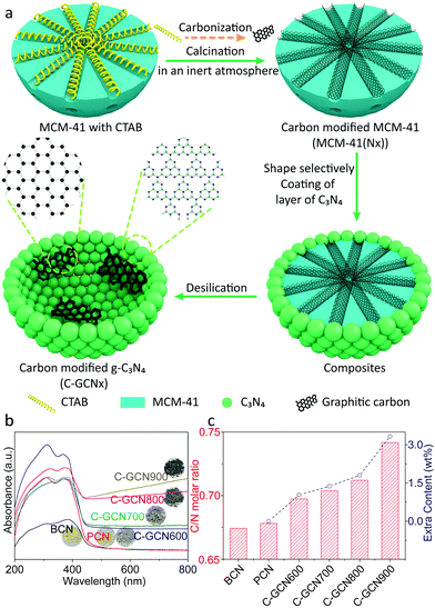
MCM-41 is considered as one of the most important ordered mesoporous materials and typically prepared through the modified Stöber method with the assistance of CTAB micellae, which are conventionally eliminated through calcination or washing with ethanol to dredge the mesoporous channel. As CTAB uniformly distributes in the channel of MCM-41 after hydrothermal synthesis, in situ carbonization but not complete elimination will probably convert it into useful graphitic carbon species and produce carbon modified MCM-41. In other words, graphitic carbon could be introduced into the channel. Meanwhile, the shrinkage of CTAB during carbonization will retain partial ordered mesoporous distribution, which is capable of the pore size selectivity of the molecular sieves.56Fig. 1a illustrates the procedure of carbon modified C3N4 vesicles (denoted as C-GCNx). Through the shape-selective templating method, thin-shelled C3N4 particles could be coated around the carbon modified MCM-41 templates. Followed by desilication by NH4HF2 solution, C-GCNx would be obtained. Notably, MCM-41 templates with different carbon contents and graphitization degrees could be prepared at different carbonization temperatures. Meanwhile, due to the pore confinement effect, carbon species should be highly dispersed, which would be beneficial to further incorporation with the C3N4 matrix.Compared with the pristine MCM-41, MCM-41(Nx) obtained from thermal treatment under an argon atmosphere shows darker colours and gradually changes from grey to black as shown in Fig. S1,† corresponding to the temperature increase, which suggests the carbonization of CTAB and the change of the graphitic degree. Raman spectra with 532 nm excitation were recorded to verify the degree of graphitization. As shown in Fig. S2a,† the peaks at 1339 and 1592 cm−1 are assigned to the amorphous carbon species and graphitic carbon, respectively.58,59 Graphitization degree is evaluated by the intensity ratio of the amorphous carbon species (ID) to that of the graphitic carbon (IG). The higher the ratio of ID/IG, the lower the degree of graphitization. As shown in Table S1,† with the increase of calcination temperature, the ratio of ID/IG firstly decreases and then increases, reaching the minimum for the sample MCM-41(N700). These results suggest that samples prepared at 700 °C exhibit the highest degree of graphitization, and might have the highest conductivity which can facilitate electron transfer.
As the pore size distribution has a deterministic effect on the shape-selectivity, small-angle XRD patterns were recorded and are shown in Fig. S2b.† As displayed in Fig. S2b,† pristine MCM-41 exhibits an obvious diffraction peak at 2.54°, indicating the uniform mesoporous size distribution. In comparison, all MCM-41(Nx) samples exhibit the diffraction peak but with much weaker intensity, suggesting that carbon residues remained with MCM-41 and absorbed partial X-ray. Meanwhile, a gradually right-shifted diffraction peak from 2.48° to 2.95° was observed, suggesting the narrowed channel according to Bragg's law (2d![[thin space (1/6-em)]](https://www.rsc.org/images/entities/char_2009.gif) sin
sin![[thin space (1/6-em)]](https://www.rsc.org/images/entities/char_2009.gif) θ = nλ), thus concluding that certain carbon species are confined in the channel of MCM-41. Meanwhile, the residue graphitic carbon gradually increases with the temperature increasing, as evidenced by elemental analysis (Table S1†).
θ = nλ), thus concluding that certain carbon species are confined in the channel of MCM-41. Meanwhile, the residue graphitic carbon gradually increases with the temperature increasing, as evidenced by elemental analysis (Table S1†).
Nitrogen physical adsorption–desorption isotherms were recorded and are shown in Fig. S2c,† with the pore size distribution and textural properties shown in Fig. S2d† and in Table S2.† Compared with pristine MCM-41, MCM-41(N600) and MCM-41(N700) exhibit a similar pore size distribution at 1.0–2.8 nm centred at 1.96 nm. Elemental analysis results suggest that samples MCM-41(N600) and MCM-41(N700) have a low carbon content of 1.23 and 1.37 wt%. For samples MCM-41(N800) and MCM-41(N900), the pore size distribution decreases to a value of 1.69 nm and <1 nm, corresponding to the increase of carbon content to 2.20 and 3.05 wt%, respectively. TEM-mapping images of MCM-41(N700) (Fig. S3†) reveal the uniform distribution of graphitic carbon inside the channel. On the basis of the above results, high temperature carbonation did not destroy the silicon skeleton of MCM-41. At the same time, highly dispersed graphitic carbon species exist uniformly in the ordered channels of MCM-41. The shrinkage of CTAB during carbonation dredges MCM-41. As the MCM-41(Nx) sample maintains a relatively larger pore size than the diameter of melamine molecules, shape-selectivity is retained. The relatively larger pore allows melamine diffusion along the channel, while further polymerization into C3N4 is forbidden due to the confinement of the channel size, which eventually leads to the generation of a thin-shell C3N4 vesicle structure. The as-prepared carbon-modified C3N4 vesicles were denoted as C-GCNx.
UV-DRS spectra were recorded to investigate the photoabsorption properties of the tailored C3N4 (Fig. 1b). Compared with BCN, PCN presents an obvious nearly 2.1 times higher photoabsorption (e.g. at 400 nm), attributed to the light scattering effect.60 As to the carbon modified C-GCNx, photoabsorption further enhances in the visible light range, corresponding to the colour changes from yellow for PCN to grey for C-GCNx. This suitable optical absorption enhancement would be beneficial to photocatalysis. Fig. 1c shows the elemental analysis results. Due to the existence of uncondensed amino groups, the C/N molar ratio of BCN is lower than the ideal value of 0.75. Compared with BCN, the C/N molar ratio of PCN exhibits a certain improvement and reaches 0.678, suggesting that MCM-41 can enhance the polymerization of melamine. With the graphitic carbon content in MCM-41 templates increasing, the residue graphitic carbon content of C-GCNx also increases gradually. Assuming that the composition of the C3N4 matrix in C-GCNx is consistent with that of PCN, the calculated carbon content is shown in Fig. 1c. The increase of the extra carbon content from 1.0 wt% for C-GCN600 to 3.3 wt% for C-GCN900 suggests partial graphitic carbon remaining, further confirming that the facile method is feasible for the combination of graphitic carbon with C3N4.
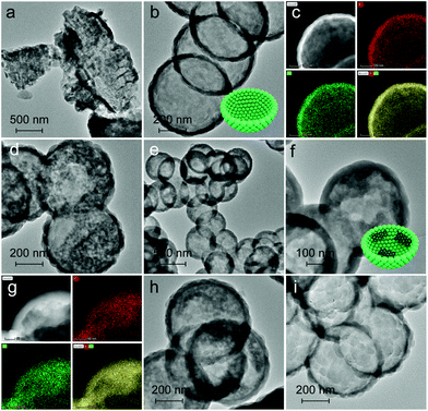
The morphology and elemental distribution were characterized in terms of TEM and TEM-mapping (Fig. 2). BCN prepared without MCM-41 presents a dense and bulk morphology as reflected in Fig. 2a. In contrast, PCN (Fig. 2b and c) exhibits a thin-shell vesicle structure with no visualized substances existing inside and uniform distribution of carbon and nitrogen elements, suggesting the composition of PCN, which is consistent with our previous work.56 This is due to the fact that the relatively narrow channel of pristine MCM-41 allows melamine and its oligomer to diffuse inside. In comparison, C-GCN600 (Fig. 2d) also exhibits a vesicle structure but with impurities inside, confirming that the graphitic carbon is retained from the MCM-41(Nx) templates. With the carbonization temperature increasing, the preservation of shape-selectivity of MCM-41(Nx) enables the as-prepared C3N4 hybrids to maintain the thin-shell vesicle structure. As the multiple reflection effect occurs on the internal surface of C3N4 vesicles, excessive graphitic carbon attached on the inner wall of the shell would lead to the waste absorption of photons by graphitic carbon. Notably, the uniform coexistence of carbon and nitrogen is observed inside C-GCN700 (Fig. 2g). Although the encapsulation of graphitic carbon can promote photoabsorption as evidenced by the UV-DRS spectra, excessive carbon might not be beneficial to photocatalytic reactions.
The textural properties of the tailored C3N4 were measured by XRD, FT-IR and XPS (Fig. 3 and Fig. S5 and S6†). The (100) and (002) diffraction peaks of BCN at 13.0° and 27.8° are associated with the in-plane repeated heptazine and the inter-layer structural stacking units.61 Compared with BCN, the peak intensity of PCN is obviously reduced, corresponding to the lower degree of crystallinity. Compared with PCN, the 002 diffraction patterns of C-GCN700 show no shift but smaller intensity, which might be attributed to a low degree of crystallinity of C3N4 or the encapsulated graphitic carbon that could absorb partial X-ray during XRD characterization. Meanwhile, all C-GCNx almost exhibit the same XRD peaks (Fig. S5†), suggesting that the graphitic carbon remaining in the channel of MCM-41 did not affect the polymerization of melamine into C3N4. FT-IR spectra (Fig. S6†) were recorded to evidence the functional groups and existing forms of nitrogen. All samples present similar FT-IR spectra of the typical g-C3N4. The absorption band at 810 cm−1 is assigned to the breathing mode of triazine units. The strong bands in the region of 1200–1650 cm−1 are attributed to the skeletal stretching vibration modes of heptazine heterocycles. The broad band around 3400 cm−1 originated from the O–H and N–H vibration, which comes from the uncondensed amino groups and the adsorbed moisture.62
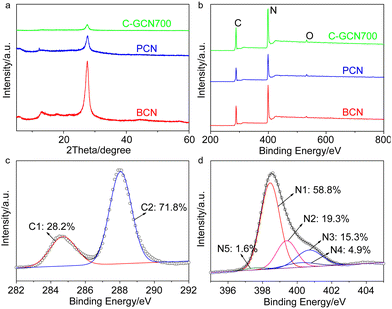 | ||
| Fig. 3 (a) XRD patterns and (b) XPS spectra of BCN, PCN and C-GCN700. Corresponding high resolution (c) C 1s and (d) N 1s spectra of C-GCN700. | ||
XPS measurements were conducted to further study the chemical states of the tailored C3N4. The C 1s peak at 287.8 eV, N 1s at 398.7 eV and O 1s at 532.5 eV are observed from survey XPS spectra (Fig. 3b). The oxygen comes from the adsorbed oxygen species like molecular oxygen and water.63 High resolution N 1s spectra (Fig. 3d) show that C-GCN700 consists of 58.8% pyridinic nitrogen (N1, 398.5 eV), 19.3% tertiary nitrogen (N2, 399.4 eV), 15.3% amino functional groups (N3, 400.7 eV), 4.9% pyrrolic nitrogen (N4, 400.2 eV) and 1.6% N-graphitic carbon (N5, 397.6 eV),64 whereas no N4 and N5 signals can be detected in pristine C3N4 (PCN) vesicles (Fig. S7†). The 1.6% nitrogen-graphitic carbon peak could be attributed to the formation of C–N–C bonding,65 which serves to link the graphitic carbon with C3N4 vesicles. The effective incorporation of the graphitic carbon and C3N4 could be beneficial to the charge transfer from C3N4 to the graphitic carbon, thus enhancing electron separation. The sample BCN exhibits a similar XPS spectrum (Fig. S8†) to PCN, indicating its typical g-C3N4 structure.
Photoluminescence (PL) spectra were usually used to characterize charge separation efficiency, because PL emission mainly arises from charge recombination.66 The effective separation of photogenerated charge carriers upon graphitic carbon modified C3N4 vesicles was confirmed by the steady-state PL emission spectra (Fig. 4a). In contrast to the strong emission peak of BCN, PCN exhibits extremely weaker intensity, implying that the recombination of charge carriers is greatly inhibited. When further introducing graphitic carbon into C3N4 vesicles, a much weaker PL intensity is observed, thus indicating that radiative recombination in C-GCN700 is greatly suppressed by the graphitic carbon species. This result was further evidenced by the time-resolved PL spectra in Fig. 4b. The average PL lifetime (Table S3†) of C-GCN700 is 3.90 ns, longer than that of BCN (2.58 ns) and PCN (3.49 ns), which is attributed to the synergy of the vesicle structure and the incorporation of graphitic carbon species. As PCN and C-GCN700 present a thin-shell vesicle structure compared with the bulk of BCN, it would shorten the distance for charge carriers to transfer to the surface, therefore restraining their recombination. When compared with PCN, the photogenerated electrons in C-GCN700 would transfer from the conduction band to the carbon species, facilitating the charge separation and prolonging the lifetime. The prolonged lifetime facilitates the exciton diffusion to a longer distance for catalytic reactions before recombination, thus increasing the possibility of charges reacting with reactants. This might result in the enhanced charge separation efficiency of C-GCN700, beneficial to photocatalytic performance. To ensure this, the electrochemical impedance spectroscopy (EIS) Nyquist plot was studied (Fig. 4c). It is observed that the arc radius of the C-GCN700 catalyst is much smaller than that of BCN and PCN. This decreased arc radius indicates a smaller resistance of C-GCN700 and could be beneficial to the interfacial charge transfer on the surface of C-GCN700. Furthermore, the effect of incorporation of graphitic carbon with C3N4 was shown in photocurrent responses (Fig. 4d). The 3.3 times enhancement of photocurrent of C-GCN700 compared to that of PCN indicates the improved charge separation in C-GCN700 due to the graphitic carbon cocatalysts. Therefore, the above PL, EIS and photocurrent studies clearly reveal the exact role of graphitic carbon in the charge separation and transfer properties of C-GCN700. Overall the graphitic carbon incorporated with C3N4 has a significant effect on photoabsorption, charge separation and transfer, which would improve its photocatalytic activity.
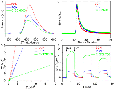 | ||
| Fig. 4 (a) Steady-state PL spectra (λex = 310 nm), (b) time-resolved PL spectra (λex = 400 nm), (c) EIS Nyquist plots and (d) photocurrent response of BCN, PCN and C-GCN700. | ||
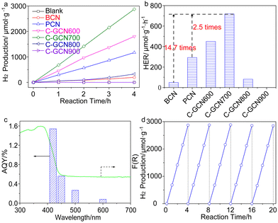
The band edge position was established (Table S4†), which is sufficient to drive the photocatalytic water splitting reaction. Fig. 5a shows the photocatalytic hydrogen production results under visible light irradiation using triethanolamine (TEA) as a sacrificial reagent and platinum as a co-catalyst. In the absence of photocatalysts, no hydrogen is detected within four hours. As shown in Fig. 5a and b, the H2 evolution rate of PCN reaches 293.1 μmol g−1 h−1, which is 6.0 times higher than that of BCN (48.9 μmol g−1 h−1) and attributed to the enhanced photoabsorption as evidenced by the UV-DRS spectra (Fig. 1b). In contrast, C-GCN700 presents the highest H2 evolution rate of 718.1 μmol g−1 h−1, which is 14.7 times and 2.5 times higher than that of BCN and PCN, thus suggesting that C-GCN700 undergoes faster exciton transfer and the encapsulated graphitic carbon could enhance the charge separation. In the cases of C-GCN800 and C-GCN900, the decreased photoactivity is attributed to the excessive carbon shielding the active sites and increasing the non-transparency of C3N4. The apparent quantum yield (Fig. 5c) of C-GCN700 at 420 nm reaches 1.54%, nearly 10 times higher than that of BCN (0.17%). Notably, C-GCN700 is grey and shows obvious absorbance at 600 nm which is likely due to the intraband caused by carbon doping. This absorption wavelength is much longer than that of BCN and PCN. With 600 nm monochromatic light irradiation, C-GCN700 still shows the photocatalytic hydrogen evolution activity. C-GCN700 was reused for five cycles and showed no obvious deactivation of photoactivity (Fig. 5d), demonstrating its high photocatalytic stability.
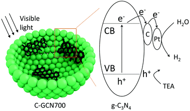
On the basis of the above results, a tentative photocatalytic mechanism is proposed (Scheme 1). Due to the multiple light reflection inside the cavity, photoabsorption was dramatically enhanced by the hollow sphere structure as evidenced by the UV-DSR absorption spectra. Upon irradiation, electrons were excited from the valence band (VB) to the conduction band (CB). Then the excited electrons were transferred to the carbon species and then to the Pt cocatalyst. In parallel, the holes in the VB were consumed by the TEA sacrificial agents. Subsequently, the captured electrons react with protons on the surface of Pt to generate H2. With graphitic carbon species inside PCN vesicles, they specifically behave as electron acceptors, facilitating the separation and transfer of charge carriers.
4. Conclusion
In summary, graphitic carbon species have been successfully fully integrated inside C3N4 vesicles and promote the charge separation and transfer, with the apparent quantum yield of C-GCN700 for H2 production at 420 nm reaching 1.54%, 10 times higher than that of the bulk CN (BCN). The special vesicle morphology and the embedded graphitic carbon simultaneously favour the visible light photoabsorption and promote the charge separation and transfer, thus achieving such an enhancement of photocatalytic water spitting for H2 production, 14.7 and 2.5 fold higher than that observed on BCN and PCN. This work provides a facile and efficient approach to the refinement of hybrid material design of metal-free hollow photocatalysts and enhancement of charge separation due to the incorporation of graphitic carbon with C3N4.Conflicts of interest
There are no conflicts to declare.Acknowledgements
L. Luo is thankful to the China Postdoctoral Science Foundation (Grant No. 2019M663802) and J. Ma is also grateful to the National Natural Science Foundation of China (21973075).Notes and references
- Y. Wang, A. Vogel, M. Sachs, R. S. Sprick, L. Wilbraham, S. J. A. Moniz, R. Godin, M. A. Zwijnenburg, J. R. Durrant, A. I. Cooper and J. Tang, Nat. Energy, 2019, 4, 746 CrossRef CAS.
- X. Wang, K. Maeda, A. Thomas, K. Takanabe, G. Xin, J. M. Carlsson, K. Domen and M. Antonietti, Nat. Mater., 2009, 8, 76 CrossRef CAS PubMed.
- D. T. Martin, K. Qiu, S. A. Shevlin, A. D. Handoko, X. Chen, Z. Guo and J. Tang, Angew. Chem., 2014, 126, 9394 CrossRef.
- J. Hou, S. Cao, Y. Wu, F. Liang, Y. Sun, Z. Lin and L. Sun, Nano Energy, 2017, 32, 359 CrossRef CAS.
- W. Tu, Y. Li, L. Kuai, Y. Zhou, Q. Xu, H. Li, X. Wang, M. Xiao and Z. Zou, Nanoscale, 2017, 9, 9065 RSC.
- C. Ling, X. Niu, Q. Li, A. Du and J. Wang, J. Am. Chem. Soc., 2018, 140, 14161 CrossRef CAS PubMed.
- X. Chen, N. Li, Z. Kong, W.-J. Ong and X. Zhao, Mater. Horiz., 2018, 5, 9 RSC.
- S. Wang, X. Hai, X. Ding, K. Chang, Y. Xiang, X. Meng, Z. Yang, H. Chen and J. Ye, Adv. Mater., 2017, 29, 1701774 CrossRef PubMed.
- Y. Zhao, Y. Zhao, R. Shi, B. Wang, G. I. N. Waterhouse, L. Z. Wu, C. H. Tung and T. Zhang, Adv. Mater., 2019, 31, 1806482 CrossRef PubMed.
- S. Wu, X. Tan, J. Lei, H. Chen, L. Wang and J. Zhang, J. Am. Chem. Soc., 2019, 141, 6592 CrossRef CAS PubMed.
- J. Xie, R. Jin, A. Li, Y. Bi, Q. Ruan, Y. Deng, Y. Zhang, S. Yao, G. Sankar, D. Ma and J. Tang, Nat. Catal., 2018, 1, 889 CrossRef CAS.
- X. Chen, Y. Li, X. Pan, D. Cortie, X. Huang and Z. Yi, Nat. Commun., 2016, 7, 12273 CrossRef CAS PubMed.
- X. Yu, V. De Waele, A. Lofberg, V. Ordomsky and A. Y. Khodakov, Nat. Commun., 2019, 10, 700 CrossRef CAS PubMed.
- Y. Zhou, L. Zhang and W. Wang, Nat. Commun., 2019, 10, 506 CrossRef CAS PubMed.
- H. Song, X. Meng, Z.-j. Wang, H. Liu and J. Ye, Joule, 2019, 3, 1606 CrossRef CAS.
- F. K. Kessler, Y. Zheng, D. Schwarz, C. Merschjann, W. Schnick, X. Wang and M. J. Bojdys, Nat. Rev. Mater., 2017, 2, 17030 CrossRef CAS.
- W. J. Ong, L.-L. Tan, Y. H. Ng, S.-T. Yong and S.-P. Chai, Chem. Rev., 2016, 116, 7159 CrossRef CAS PubMed.
- S. Bai, N. Zhang, C. Gao and Y. Xiong, Nano Energy, 2018, 53, 296 CrossRef CAS.
- W. Zhang, H. He, Y. Tian, H. Li, K. Lan, L. Zu, Y. Xia, L. Duan, W. Li and D. Zhao, Nano Energy, 2019, 66, 104113 CrossRef CAS.
- P. Niu, M. Qiao, Y. Li, L. Huang and T. Zhai, Nano Energy, 2018, 44, 73 CrossRef CAS.
- Z. Zhu, H. Pan, M. Murugananthan, J. Gong and Y. Zhang, Appl. Catal., B, 2018, 232, 19 CrossRef CAS.
- J. Ran, T. Y. Ma, G. Gao, X.-W. Du and S. Z. Qiao, Energy Environ. Sci., 2015, 8, 3708 RSC.
- C. Liu, H. Huang, W. Cui, F. Dong and Y. Zhang, Appl. Catal., B, 2018, 230, 115 CrossRef CAS.
- Z. Qin, Z. Huang, M. Wang, D. Liu, Y. Chen and L. Guo, Appl. Catal., B, 2020, 261, 118211 CrossRef CAS.
- L. Luo, A. Zhang, M. J. Janik, K. Li, C. Song and X. Guo, Appl. Surf. Sci., 2017, 396, 78 CrossRef CAS.
- L. Luo, A. Zhang, M. J. Janik, C. Song and X. Guo, RSC Adv., 2016, 6, 94496 RSC.
- Z. Chen, S. Lu, Q. Wu, F. He, N. Zhao, C. He and C. Shi, Nanoscale, 2018, 10, 3008 RSC.
- Y. Chen and X. Wang, J. Phys. Chem. C, 2018, 122, 3786 CrossRef CAS.
- Z. Tong, D. Yang, Z. Li, Y. Nan, F. Ding, Y. Shen and Z. Jiang, ACS Nano, 2017, 11, 1103 CrossRef CAS PubMed.
- Y. Si, Z. Sun, L. Huang, M. Chen and L. Wu, J. Mater. Chem. A, 2019, 7, 8952 RSC.
- J. Low, J. Yu, M. Jaroniec, S. Wageh and A. A. Al-Ghamdi, Adv. Mater., 2017, 29, 1601694 CrossRef PubMed.
- H. Yang, R. Cao, P. Sun, J. Yin, S. Zhang and X. Xu, Appl. Catal., B, 2019, 256, 117862 CrossRef CAS.
- Z.-Y. Liang, M.-H. Huang, S.-Y. Guo, Y. Yu, W. Chen and F.-X. Xiao, Catal. Sci. Technol., 2019, 9, 672 RSC.
- T. Li, Y.-B. Li, X.-C. Dai, M.-H. Huang, Y. He, G. Xiao and F.-X. Xiao, J. Phys. Chem. C, 2019, 123, 4701 CrossRef CAS.
- Z.-Y. Liang, J.-X. Wei, X. Wang, Y. Yu and F.-X. Xiao, J. Mater. Chem. A, 2017, 5, 15601 RSC.
- B. Jin, E. Jung, M. Ma, S. Kim, K. Zhang, J. I. Kim, Y. Son and J. H. Park, J. Mater. Chem. A, 2018, 6, 2585 RSC.
- B. Qiu, Q. Zhu, M. Du, L. Fan, M. Xing and J. Zhang, Angew. Chem., Int. Ed., 2017, 56, 2684 CrossRef CAS PubMed.
- L. Zhou, Z. Zhuang, H. Zhao, M. Lin, D. Zhao and L. Mai, Adv. Mater., 2017, 29, 1602914 CrossRef PubMed.
- J. Qi, K. Zhao, G. Li, Y. Gao, H. Zhao, R. Yu and Z. Tang, Nanoscale, 2014, 6, 4072 RSC.
- X. Wang, M. Liao, Y. Zhong, J. Y. Zheng, W. Tian, T. Zhai, C. Zhi, Y. Ma, J. Yao, Y. Bando and D. Golberg, Adv. Mater., 2012, 24, 3421 CrossRef CAS PubMed.
- D. Zheng, X. N. Cao and X. Wang, Angew. Chem., Int. Ed., 2016, 55, 11512 CrossRef CAS PubMed.
- R. Li, F. Zhang, D. Wang, J. Yang, M. Li, J. Zhu, X. Zhou, H. Han and C. Li, Nat. Commun., 2013, 4, 1432 CrossRef PubMed.
- Y. Wang, W. Yang, X. Chen, J. Wang and Y. Zhu, Appl. Catal., B, 2018, 220, 337 CrossRef CAS.
- C. Pan, J. Xu, Y. Wang, D. Li and Y. Zhu, Adv. Funct. Mater., 2012, 22, 1518 CrossRef CAS.
- C. Dai, S. Zhang, A. Zhang, C. Song, C. Shi and X. Guo, J. Mater. Chem. A, 2015, 3, 16461 RSC.
- J. Liu, H. Xu, Y. Xu, Y. Song, J. Lian, Y. Zhao, L. Wang, L. Huang, H. Ji and H. Li, Appl. Catal., B, 2017, 207, 429 CrossRef CAS.
- C. Xu, Q. Han, Y. Zhao, L. Wang, Y. Li and L. Qu, J. Mater. Chem. A, 2015, 3, 1841 RSC.
- Q. Xiang, J. Yu and M. Jaroniec, J. Phys. Chem. C, 2011, 115, 7355 CrossRef CAS.
- A. Du, S. Sanvito, Z. Li, D. Wang, Y. Jiao, T. Liao, Q. Sun, Y. H. Ng, Z. Zhu, R. Amal and S. C. Smith, J. Am. Chem. Soc., 2012, 134, 4393 CrossRef CAS PubMed.
- Q. Han, Z. Cheng, J. Gao, Y. Zhao, Z. Zhang, L. Dai and L. Qu, Adv. Funct. Mater., 2017, 27, 1606352 CrossRef.
- Y. Wang, Q. Xia, X. Bai, Z. Ge, Q. Yang, C. Yin, S. Kang, M. Dong and X. Li, Appl. Catal., B, 2018, 239, 196 CrossRef CAS.
- A. Saha, A. Moya, A. Kahnt, D. Iglesias, S. Marchesan, R. Wannemacher, M. Prato, J. J. Vilatela and D. M. Guldi, Nanoscale, 2017, 9, 7911 RSC.
- H. Zhao, S. Wang, F. He, J. Zhang, L. Chen, P. Dong, Z. Tai, Y. Wang, H. Gao and C. Zhao, Carbon, 2019, 150, 340 CrossRef CAS.
- L. Zhang, Z. Jin, H. Lu, T. Lin, S. Ruan, X. S. Zhao and Y.-J. Zeng, ACS Omega, 2018, 3, 15009 CrossRef CAS PubMed.
- J. Sun, J. Zhang, M. Zhang, M. Antonietti, X. Fu and X. Wang, Nat. Commun., 2012, 3, 1139 CrossRef.
- L. Luo, K. Li, A. Zhang, H. Shi, G. Zhang, J. Ma, W. Zhang, J. Tang, C. Song and X. Guo, J. Mater. Chem. A, 2019, 7, 17815 RSC.
- Z. Teng, X. Su, Y. Zheng, J. Sun, G. Chen, C. Tian, J. Wang, H. Li, Y. Zhao and G. Lu, Chem. Mater., 2013, 25, 98 CrossRef CAS.
- I. K. Moon, J. Lee, R. S. Ruoff and H. Lee, Nat. Commun., 2010, 1, 73 CrossRef PubMed.
- J.-B. Wu, M.-L. Lin, X. Cong, H.-N. Liu and P.-H. Tan, Chem. Soc. Rev., 2018, 47, 1822–1873 RSC.
- H. Li, Z. Bian, J. Zhu, D. Zhang, G. Li, Y. Huo, H. Li and Y. Lu, J. Am. Chem. Soc., 2007, 129, 8406 CrossRef CAS PubMed.
- L. Luo, A. Zhang, M. J. Janik, K. Li, C. Song and X. Guo, Mater. Lett., 2017, 188, 130 CrossRef CAS.
- L. Luo, A. Zhang, M. J. Janik, C. Song and X. Guo, RSC Adv., 2016, 6, 91960 RSC.
- P. Hu, C. Chen, R. Zeng, J. Xiang, Y. Huang, D. Hou, Q. Li and Y. Huang, Nano Energy, 2018, 50, 376 CrossRef CAS.
- Y. Zhao, F. Zhao, X. Wang, C. Xu, Z. Zhang, G. Shi and L. Qu, Angew. Chem., Int. Ed., 2014, 53, 13934 CrossRef CAS PubMed.
- Q. Han, B. Wang, J. Gao and L. Qu, Angew. Chem., Int. Ed., 2016, 55, 10849 CrossRef CAS PubMed.
- L. J. Fang, X. L. Wang, J. J. Zhao, Y. H. Li, Y. L. Wang, X. L. Du, Z. F. He, H. D. Zeng and H. G. Yang, Chem. Commun., 2016, 52, 14408 RSC.
Footnote |
| † Electronic supplementary information (ESI) available. See DOI: 10.1039/d0nr00226g |
| This journal is © The Royal Society of Chemistry 2020 |


