 Open Access Article
Elastic sheath–liquid crystal core fibres achieved by microfluidic wet spinning†
Lawrence W.
Honaker
 *,
Shameek
Vats
,
Manos
Anyfantakis
 and
Jan P. F.
Lagerwall
 *
*
Experimental Soft Matter Physics Group, Physics and Materials Science Research Unit, University of Luxembourg, L-1511 Luxembourg, Grand Duchy of Luxembourg. E-mail: lhonaker@kent.edu; jan.lagerwall@lcsoftmatter.com
First published on 2nd September 2019
Abstract
While coaxial polymer sheath–liquid crystal core fibres attract interest for fundamental research as well as applied reasons, the main method for achieving them so far, electrospinning, is complex and has significant limitations. It has proven particularly challenging to spin fibres with an elastic sheath. As an alternative approach, we present a microfluidic wet spinning process that allows us to produce liquid crystal core–polyisoprene rubber sheath fibres on a laboratory scale. The fibres can be stretched by up to 300% with intact core–sheath geometry. We spin fibres with nematic as well as with cholesteric liquid crystal in the core, the latter turning the composite fibre into an elastic cylindrical photonic crystal. Iridescent colours are easily observable by the naked eye. As this coaxial wet spinning should be amenable to upscaling, this could allow large-scale production of innovative functional fibres, attractive through the various responsive characteristics of different liquid crystal phases being incorporated into an elastic textile fiber form factor.
Introduction
The field of smart textiles and wearable technology is a fast-growing domain of research. An interest in this field is to incorporate sensors and sensing-capable materials that do not rely on electrical power into fibres to be used in yarns and other textiles. Many methods exist for the production of coaxial fibres consisting of a polymer sheath with a functional heterocore, such as a liquid crystal. These range from phase separation techniques, where a heterocore separates from the sheath as a result of a change in solution composition during production,1–4 to coating techniques which coat a passive textile with a responsive/reactive material,5 and coaxial electrospinning, which produces core–sheath fibres by drawing materials from co-flowing liquids using an electric field.6–15 These techniques aim to produce fibres with continuous cores during the fibre production process itself without the need for later filling of the fibre, in direct contrast to processes employed in commonly-used techniques for producing liquid metal core fibres.16 In addition to the simultaneous spinning being a much simpler one-step process, spinning both the fibre sheath and core simultaneously also expands the possible range of accessible fibre sizes. Simultaneous spinning allows the achievement of extremely thin fibres that cannot be created through simple capillary filling, with diameters of as small as a few micrometres.13,17Some of the advantages of electrospinning are that the set-ups are readily adapted to laboratory settings and that it allows the incorporation of liquid crystals,6,9,13,17 liquids that show anisotropic physical properties thanks to long-range orientational ordering of molecules that are anisotropic in shape, into fibres with diameters as low as hundreds of nanometers. Thanks to the strong responsiveness and sensitivity of liquid crystals which results from the ease of influencing the orientational ordering and thus their macroscopic physical properties, these composite fibres can then be used as platforms for sensing of various stimuli, ranging from temperature to biological or chemical analytes.2,6,7,9,18–20
On the other hand, the range of polymers suitable for electrospinning is somewhat limited,15 with minimal success achieved by using elastomers, in part due to the volatile, nonpolar solvents needed to dissolve them.21,22 This reveals a need for a technique better suited to spinning fibres with an elastomeric sheath and a functional heterocore.
Wet spinning techniques are a less-explored option for the production of coaxial fibres. Wet spinning techniques pump a polymer dope (a solution of a polymer and its solvent from which fibres are obtained) into a coagulation bath tuned to extract the dope solvent, leaving a continuous polymer fibre behind.23–26 Careful tuning of ratios between the flow rates of the polymer dope and the coagulation bath and composition of the coagulation bath are necessary to produce the desired outcomes of a jet that leads to continuous fibres.23,25 Jetting results from a balance between interfacial tension forces, which favour the collapse of a jet into droplets due to Plateau–Rayleigh instability, and inertial and viscous forces that promote jet stability and dampen the propagation of instabilities along the jet length.27,28 Wet spinning is a technique that scales well to industrial production, already being employed in the production of textile fibres from materials such as acrylics26 and polyamides.29 To our knowledge, however, no work has been undertaken in the production of core–sheath fibres using a wet spinning approach, particularly those incorporating a liquid crystalline core.
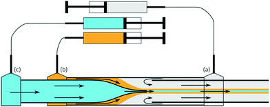
In this work, we present a protocol for microfluidic wet spinning of fibres that incorporate both a rubbery polymer into the sheath and a liquid crystal into the core. This protocol shows both the production of microscale elastomer fibres within the scale of an ordinary chemistry laboratory and the incorporation of the heterocore into the same. The combination of an optimised coagulation bath and balanced spinning parameters help to solidify the fibre.
Experimental
Materials and methods
For the experiments described in this paper, the coagulation bath contained, apart from the solvent, 10% w/w polyvinylpyrrolidone (PVP, Mw = 1.3 Mg mol−1, Aldrich), which functions as a flow stabiliser by counteracting the Rayleigh instability by means of its very high molar mass and the resulting entanglements between chains, as well as by increasing the viscosity of the bath. We also added a salt, either magnesium sulphate (MgSO4, Aldrich), lithium bromide (LiBr, Aldrich), or calcium chloride (CaCl2, Merck) in order to create a diffusion gradient to better drive the extraction of the dope solvent.31 PVP is preferred over stabilisers such as poly(vinyl alcohol) due to the latter's insolubility in ethanol, the main component of the coagulation bath when working with organic dope solvents. MgSO4 is sparingly soluble in ethanol, with a maximum concentration of 0.1% w/w, whereas LiBr and CaCl2 are both readily soluble at concentrations of at least 10% w/w. The coagulation baths were left to stir gently (120–200 rpm) at approximately 30–40 °C overnight until a macroscopically homogeneous solution was obtained.
To collect the fibres, we additionally prepared hydrophobised glass slides: as reported by Kim et al.32 and by Kye et al.,8 the use of hydrophobic substrates is necessary to avoid fibre collapse during the drying process. This was done by the silanisation of the glass surfaces, similar to the method used for treating the glass capillaries, followed by baking at 115 °C under vacuum for at least 30 min and then left to dry overnight at room temperature.
Results and discussion
Pure elastomer fibres
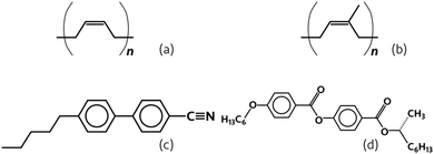
The choice of solvent for the polymer dope is important. When using n-hexane or toluene as the solvent for the elastomer and ethanol in the coagulation bath, fibres were readily obtained. The optimum concentration of polymer in solution was, in the case of PI, 14% w/w in n-hexane and 12.5% w/w in toluene, with the lower required concentration in toluene being a result of toluene being a better solvent for the polymer compared to n-hexane. In contrast, THF and n-decane are not suitable candidates, and each for a different reason. In the case of n-decane, even in the presence of salt, it does not get extracted from the jet quickly enough to produce fibres before the onset of Rayleigh instability, which is likely a consequence of the aliphatic chain length of n-decane and its poorer miscibility with ethanol. On the other hand, THF is extracted too quickly, consistently clogging the spinneret devices. The polymer concentration within the spinning dope also was important to control: for concentrations of greater than approximately 14% w/w PB or PI in n-hexane or 12.5% w/w in toluene, the solution could not be spun into fibres using our microfluidics set-up, the viscosity being too high. Similarly, at concentrations below about 11% w/w, the relatively low viscosity of the dope solution led to a fast development of Rayleigh instability between the bath and the dope in the jet.
Fibres are obtainable with relatively low flow rates of both bath and dope, ranging from 0.75–1.75 mL h−1 bath flow rate and 0.25–1.00 mL h−1 dope flow rate. When spinning PI, lower dope flow rates than those needed to spin PB were needed, most likely due to the higher molecular weight creating more entanglements, thus suppressing the onset of Rayleigh instability. The strategy of selecting polymers with longer chains, when possible, is similar to the case in electrospinning and other fibre spinning techniques, where the use of high-mass polymers can improve the spinning process.33 The higher molar mass is why we prefer to produce fibres from PI, which will be the primary material used in the fibres presented in this article.
A relatively high flow rate for the bath is used to better and more continuously refresh the solution, helping to drive the extraction of solvent from the dope. Since our fibre production technique relies on the extraction of solvent from the dope, constantly renewing the bath prevents it from becoming saturated with dope solvent, allowing for a faster and more continuous solvent removal. On the other hand, a high flow rate of bath solvent, if solvent extraction does not happen quickly enough, thins the jet to the point of breaking. This is akin to the process of droplet generation in flow-focussing geometries.34–36 We found the best jetting, where robust fibres capable of being easily handled were obtained within the length of the tubing, to be with flow rate ratios between the bath and polymer dope around 4![[thin space (1/6-em)]](https://www.rsc.org/images/entities/char_2009.gif) :
:![[thin space (1/6-em)]](https://www.rsc.org/images/entities/char_2009.gif) 1. We could obtain extremely thin fibres with flow rate ratios of bath to dope of as high as 20
1. We could obtain extremely thin fibres with flow rate ratios of bath to dope of as high as 20![[thin space (1/6-em)]](https://www.rsc.org/images/entities/char_2009.gif) :
:![[thin space (1/6-em)]](https://www.rsc.org/images/entities/char_2009.gif) 1, but the resulting fibres were fragile and difficult to handle, and incorporating a liquid crystal core into such a thin fibre is extremely difficult. An example of such jetting can be seen in Fig. S1, S2 and in Videos S1, S2 (ESI†).
1, but the resulting fibres were fragile and difficult to handle, and incorporating a liquid crystal core into such a thin fibre is extremely difficult. An example of such jetting can be seen in Fig. S1, S2 and in Videos S1, S2 (ESI†).
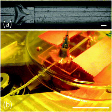
We explored several methods of collecting the fibres. Continuous fibres could be collected on copper wire frames, directly drawn on the surface of an ethanol bath, or collected on a hydrophobised collector, such as a silanised glass slide. We observed that fibres stored on hydrophilic glass, such as an untreated glass slide, would collapse and be largely undetachable from the substrates, as noted also in previous work by Kim et al.9,32 and Kye et al.8 In contrast, the polymer fibres can more easily be removed from hydrophobic substrates, even after drying for over a week. The use of hydrophobised glass as supporting substrates, the collection and storage of fibres in an ethanol bath, and freely-hanging storage all were found to be suitable methods for keeping intact elastomer fibres for observation. In contrast, storage on copper wire frames consistently led to fibre breakage: this is likely a consequence of a strong tension that develops as the fibre dries, which thus leads to breakage.
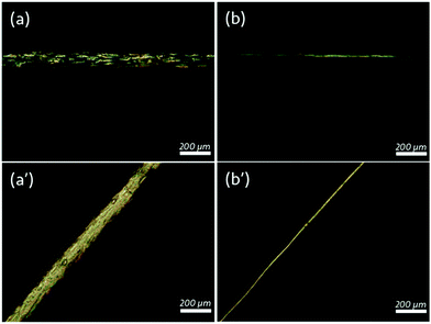
Thinning the fibres by additional manual stretching showed greater birefringence within the length of the fibre, though the observed birefringence overall was uniformly coloured and corresponded to the lower orders described by the Michel–Lévy diagram. Using the Michel–Lévy diagram, we can estimate the birefringence of a typical fibre with a diameter of 30 μm as 0.004.39 This value, while low, makes sense due to a completely unstretched fibre not showing any visible birefringence: the anisotropy induced by stretching is quite low, so the corresponding birefringence should also be of a low magnitude.
Even very thin polymer fibres were extremely stretchable, capable of undergoing a maximum strain of well over 500% before breaking. However, upon release of stretching, the fibres would restore only to an already-stretched state of about 300–400% strain. This is probably because the stretching of these fibres disentangles the polymer chains without a sufficient restoring force to restore the original configuration. The unstretched fibres started with diameters of about 70–100 μm and could be readily thinned by stretching to 25–40 μm without breaking. An example of the high degree of stretching achievable with a fibre is shown in Video S4 (ESI†).
Fibres with liquid crystal cores
Extraction of the dope solvent into the coagulation bath proceeds similarly here to the case when no core was spun into the fibres. The difference is that the solvent for the sheath is miscible with both the liquid crystal core phase and the coagulation bath. This additional solubility can have a drastic effect on the outcome of the spinning process, since the addition of solvent to a liquid crystal can have a significant impact on its phase diagram, with even a small amount of solvent (such as ethanol or hexane) substantially decreasing the clearing point and potentially triggering phase separation, leading to an isotropic liquid without any visible birefringence or colour.6,40 The addition of salt to the coagulation bath helps to solve this issue, as the dope solvent is more likely to diffuse along the gradient into the region of higher solute concentration (here, the salt) and the salt, in turn, is not significantly soluble in the dope solvent.41 We are also able to further mitigate the effect of core and sheath solvent miscibility by the use of an RO-TN-class mixture as the core when ethanol is used as the bath solvent due to the reduced miscibility of RO-TN mixtures with ethanol compared to that of 5CB. The result is that the leaching of core material into the ethanol bath is much less favourable than the extraction of hexane into the same, thus promoting the maintenance of core contiguity.
The readiness of the liquid crystal to remain within the cores of the fibres is also very much a consequence of the balancing of the parameters influencing the jetting. As reported by Utada et al.27 and by Castro-Hernández et al.,28 the transition between a regime where the jet breaks apart into droplets and where the jet continues unbroken requires a balance of inertial or viscous forces against interfacial forces. In non-turbulent flows, such as in the spinneret device, the relevant balance is between the viscous forces which dampen the propagation of Rayleigh instability within the jet against the interfacial forces which contribute to it.28 While it may appear at first that miscibility of the core with the sheath polymer solvent is not desirable for keeping a continuous core, Lacaze et al. reported that a small degree of miscibility between the phases drastically reduces the interfacial tension,42 on the order of 10−7 mN m−1. This extremely low interfacial tension allows the viscous forces to dominate, resulting in jetting as opposed to instability and break-up: this phenomenon contributes to the jet stability at both the bath-dope and dope-liquid crystal interfaces, though the stability at the former is additionally assisted by the solvent extraction from the polymer dope.
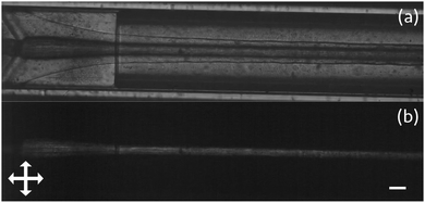
Verification of core contiguity takes place by viewing the fibre spinning process between crossed linear polarisers: since the polymer solution shows no birefringence in the microfluidic device, even under flow, any visible birefringence observed between crossed polarisers would come solely from the liquid crystal. The most contiguous cores were observed with flow rates of 0.60 mL h−1 and 0.75 mL h−1 core with a dope flow rate of 0.45 mL h−1 (corresponding to flow rate ratios of 4![[thin space (1/6-em)]](https://www.rsc.org/images/entities/char_2009.gif) :
:![[thin space (1/6-em)]](https://www.rsc.org/images/entities/char_2009.gif) 3 and 5
3 and 5![[thin space (1/6-em)]](https://www.rsc.org/images/entities/char_2009.gif) :
:![[thin space (1/6-em)]](https://www.rsc.org/images/entities/char_2009.gif) 3 of liquid crystal to dope, respectively). With a liquid crystal to dope flow rate ratio closer to 2
3 of liquid crystal to dope, respectively). With a liquid crystal to dope flow rate ratio closer to 2![[thin space (1/6-em)]](https://www.rsc.org/images/entities/char_2009.gif) :
:![[thin space (1/6-em)]](https://www.rsc.org/images/entities/char_2009.gif) 1, we saw that there was additionally some leakage of the liquid crystal from the jet, which explains the additional bright signal in that image (images of the process are presented in the ESI†).
1, we saw that there was additionally some leakage of the liquid crystal from the jet, which explains the additional bright signal in that image (images of the process are presented in the ESI†).
Fibres are collectable with the same techniques as collecting the pure polymer fibres, though we found that storing the fibres under ethanol resulted in the liquid crystal and, where present, the dye (such as Sudan Black) leaching from the fibres, resulting in the loss of the functional core as indicated by the greatly reduced birefringence. This is most likely a result of the liquid crystal swelling the rubber, which is predicted from the very similar solubility parameters of PI and common liquid crystals: by using methods suggested by Fedors43 and Hansen44,45 and data from Araya et al.,46 the solubility parameters of, for example, 5CB (as a representative liquid crystal) and PI suggest some miscibility of the 5CB with the PI and consequent swelling of the polymer by the liquid crystal. Similarly, the ZLI-3786 also may induce swelling of the PI, as suggested by its structure (detailed calculations of the Hansen solubility parameters can be found in the ESI†). Thus, although ethanol is not a solvent of PI, it comes into contact with the 5CB/liquid crystal since the material is present in both the sheath and the core. As the sheath-dissolved 5CB is then dissolved into the ethanol, more 5CB diffuses from the core into the sheath to take its place, eventually depleting the fibres of the liquid crystal.
Similar to the pure elastomer fibres, collection of fibres on hydrophobised substrates was found to both prevent fibre collapse and keep the core relatively intact for short periods, but the swelling of the liquid crystal into the polymer itself shortened the lifespan of the available fibres for collection (when stored on glass slides, fibres could be kept for up to a week). We presume this is at least partly due to the liquid crystal acting as a plasticiser for the elastomer, causing it to become softened with time:18 its solubility in the elastomer additionally contributes to the softening phenomenon we see.
Birefringence due to the liquid crystal was seen throughout the fibre, as viewed between crossed polarisers. A filled fibre is presented in Fig. 6. Regardless of the diameter of the fibres, if liquid crystals were incorporated into the fibre during the spinning process, the observed birefringence was markedly different from that of the fibres spun without a liquid crystal core, displaying bright, higher-order colours from the Michel–Lévy diagram,39 corresponding to higher first order up to second order, throughout the length of the fibre. Very thick (>80 μm) fibres did not show strong alignment of the liquid crystal contained within the core, though there was often enough aligned material where the brightness became visibly reduced upon rotation between crossed polarisers. Some samples of these thicker fibres are shown in Fig. 7. The liquid crystal-filled fibres were generally thicker than the unfilled fibres, the likely source of this being the thickness of the jet of liquid crystal in the spinneret: from a spinneret with an orifice of 60 μm, for example, the minimum jet diameter appeared to be 100 μm. With a smaller spinneret diameter, it would conceivably be possible to produce thinner cores and thinner fibres, but smaller orifices become clogged more easily.
 | ||
| Fig. 6 A PI fibre spun from a 14% w/w PI in n-hexane dope with a core consisting of the liquid crystal mixture RO-TN 615. Scale bars indicate 100 μm. (a) A fibre viewed under a single polariser. (b) The same fibre in (a) viewed between crossed polarisers; arrows indicate the direction of the linear polarisers. (c) As (b), but upon 45° clockwise rotation, showing birefringence that differs from Fig. 4(b) in being of higher order.39 | ||
Upon stretching the fibres with thinner cores, provided the fibre itself remained intact, the core remained so as well: in fact, the alignment in the core became significantly improved. This is most likely due to the aligning effect from the sheath being much stronger in thinner cores combined with a better alignment of the polymer chains upon stretching, in part due to PI promoting a degenerate planar anchoring. Because the PI is a weakly anchoring substrate, the alignment promoted by the polymer is not readily sustained through the diameter of the fibre.
In general, the maximum strain before breaking of a fibre with liquid crystal filling was much lower than the maximum strain of a liquid crystal-filled fibre: generally, about 250–300% strain was achievable. The lower maximum strain is likely a consequence of the polymer sheath being significantly thinner compared to the thickness of the pure polymer fibre. The increased fragility may also be a function of the plasticisation caused by the liquid crystal in the core leaching into the fibre sheath with time.
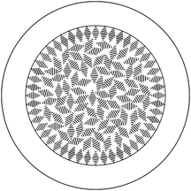
Flow rates and ratios to obtain cholesteric filling in the fibres were very similar to those used to spin PI fibres with nematic liquid crystal cores. Macroscopically, we were able to obtain fibres that generally reflected green colour under ambient light conditions, as seen in Fig. 8. Unusually, while the liquid crystal was prepared to have a reflection in the red region of the UV-Vis spectrum (as viewed by sandwiching a sample of the liquid crystal between two glass slides and observing it along the sample normal), the resulting fibres, as shown, reflect green. To explain this, we propose the following tentative model for the arrangement of the liquid crystal molecules in the core of the fibre. The liquid crystal molecules organize helically, with a constant pitch determined by the chiral dopant concentration, but the orientation of the helix axis can vary within the sample. Near the interface of the liquid crystal with the polymer sheath, the molecules are expected to adopt a planar alignment, with the helix axis aligned orthogonal to the interface, much as is the case with the alignment of liquid crystal molecules on a rubbed polymer substrate (with the ‘rubbing’ here coming from the striations of the polymer sheath that appear upon shearing during jetting).57 The aligning effect of the liquid crystal is progressively lost as we move towards the centre of the fibre; thus, the helix orientation, which has no impact on the free energy in the absence of an aligning field, varies more or less randomly. The helix pitch, in contrast, remains constant throughout the bulk, as the pitch enters the free energy expression. The bulk of the liquid crystal core is thus analogous to a ‘powder-like’ multidomain, polycrystalline material containing crystallites with different orientations, although the liquid nature of the cholesteric phase means that there are no grain boundaries, but rather continuous variations. Fig. 9 shows a schematic of the proposed liquid crystal configuration, where we for simplicity have drawn discrete ‘snippets’ of helix orientation and we have ignored the freedom to orient the helix out of the paper plane.
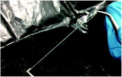 | ||
| Fig. 8 A long (∼20 cm) sample of a PI fibre filled with a mixture of 25% w/w ZLI-3786 in RO-TN 651, viewed under ambient room lighting. | ||
As suggested in the proposed configuration, the optical response comes from Bragg reflection from both the ‘powder-like’ interior and the well-aligned ‘shell’ next to the interface, but we believe the dominant reflection is from the powder-like interior. Red reflection will, for our cholesteric mixture, only occur for vertical helix alignment, which we expect at significant fractions only near the sheath at both the top and bottom of the fibre. To assess the colour reflected from the randomly aligned interior, we need to consider both the dependence of reflection colour as well as dependence of the intensity of the magnitude by which the helix tilts away from the vertical direction of the incident light (which is also the observation direction). The direction of tilt is unimportant, since it does not enter Bragg's law, nor does it affect the reflection intensity. This is akin to the statistical description of liquid crystal molecule orientation using an orientational distribution function (ODF) in the so-called ‘de Vries-type liquid crystals’.58 A full analysis would require the establishment of the ODF for the helix orientation and integration of reflection colours and intensities weighted by the ODF, an endeavour that is beyond the scope of this paper. However, since the reflection intensity goes to zero for horizontal helix orientation but the ODF will have its maximum at that tilt angle, we can estimate that the optically most relevant tilt angle should be at an intermediate tilt angle of some ∼30–40°, corresponding to a maximum strength reflection colour in the green-blue range. This matches well the overall observed reflected colour.
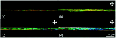
We can verify the effect and dependence of the angle of illumination on the light reflected from the fibre, as shown in Fig. 10. With normally incident light, the reflected colours were between red and green (a–b); as the angle of incidence increased to about 30°–45°, the resulting reflection (still observed in the original normal direction) shifted to green (c); and with light incident from 70°–90° with respect to the fibre normal, the reflected colour was mainly blue (d). This demonstrates that all helix orientations are present within the fibre core, such that we see significant reflection regardless of how the light is incident. With the uncontrolled angle of incidence in the macroscopic photo in Fig. 8, we thus see a superposition of multiple reflection colours.
While Enz et al. found a change in normal incidence-reflected colour as a function of fibre core thickness,13 we observed a similar phenomenon, but this was much more subtle and less obvious to the unaided eye. This is most likely due to the colour change of the cholesteric liquid crystal upon heating or cooling: stretching the fibre causes local heating due to a change in conformational entropy between the stretched and unstretched states. We see a similar effect when we heat the fibre by gentle blowing or the use of a heat gun, as can be seen in Video S6 (ESI†), when the reflected colour blueshifts before redshifting again upon cooling.
Filling of cholesteric liquid crystal into the core of the fibres did not appear to negatively affect their tensile properties compared to non-chiral nematic liquid crystal filling; in fact, stretching to strains of over 300% was still achievable from a fibre of diameter 150–200 μm while the core integrity was maintained, with a minimum diameter of approximately 35–50 μm achievable.
Conclusions
We have presented a protocol for the wet spinning of elastomer fibres incorporating a liquid crystal core, either nematic or cholesteric, throughout its length. These fibres are highly stretchable, maintaining their core integrity even under substantial strain.The primary drawback of the present technique is the minimum achievable thickness of the produced fibres from the spinneret. This can potentially be mitigated through the use of thinner capillaries to consequently thin the jets produced and through the use of more viscous materials, both in polymer dopes and in the coagulation bath, to suppress the onset of Rayleigh instability in the thinner jet. An additional issue is material-related: the liquid crystal leaches quite readily into the polymer sheath, which causes degradation of the polymer properties with time (an effect which is not seen in the pure elastomer fibres).
Further work will explore achieving thinner diameters of fibres in addition to the incorporation of both liquid metals, which have a considerably higher interfacial tension and lower miscibility with many fluids, and liquid crystal elastomer materials into the fibre cores with potential use for tensile sensors and in soft robotic actuator applications. We will also explore polysiloxanes (e.g. PDMS), which are much less miscible with most liquid crystals that might be used in the core, and look at cross-linking the fibres and exploring different materials to improve their durability.
Conflicts of interest
There are no conflicts to declare.Acknowledgements
Funding was provided in part by an Aide à la formation–recherche grant from the Luxembourg National Research Foundation (project code LIMEFLOW) and by a Consolidator Grant from the European Research Commission (project code INTERACT). The authors would like to thank the Goodyear Innovation Centre, Luxembourg, for graciously providing the cis-1,4-polybutadiene and cis-1,4-polyisoprene used in this work; Dr Ulrich Siegel, Nicolas Tournier, Dr Nicolò Maccaferri, Ricardo Rojas Aedo, and Robert Wagener for providing equipment used during both the fibre spinning and characterisation process and technical support; Dr Catherine Reyes for assisting in performing some of the characterisation and for helpful discussions; Dr V. S. R. Jampani for assistance with instrumentation and the experimental set-up and for useful discussions; and Dr Rijeesh Kizhakidathazhath, Dr Anshul Sharma, Prof Irena Drevenšek-Olenik, and Prof Margaret W. Frey for helpful discussions and feedback.Notes and references
- J. L. West, J. Wang and A. Jákli, Airbrushed Liquid Crystal/Polymer Fibers for Responsive Textiles, Adv. Sci. Technol., 2017, 100, 43–49 Search PubMed.
- J. Wang, A. I. Jákli and J. L. West, Morphology Tuning of Electrospun Liquid Crystal/Polymer Fibers, ChemPhysChem, 2016, 17, 3080–3085 CrossRef CAS PubMed.
- J. Wang, J. Kolacz, Y. Chen, A. Jákli, J. Kawalec, M. Benitez and J. L. West, Smart Fabrics Functionalized by Liquid Crystals, SID 2017 Dig., 2017, 147–149 Search PubMed.
- E. A. Buyuktanir, M. W. Frey and J. L. West, Self-assembled, optically responsive nematic liquid crystal/polymer core-shell fibers: Formation and characterization, Polymer, 2010, 51, 4823–4830 CrossRef CAS.
- Y. Guan, D. M. Agra-Kooijman, S. Fu, A. Jákli and J. L. West, Responsive Liquid-Crystal-Clad Fibers for Advanced Textiles and Wearable Sensors, Adv. Mater., 2019, 1902168, 1902168 CrossRef.
- C. G. Reyes, A. Sharma and J. P. F. Lagerwall, Non-electronic gas sensors from electrospun mats of liquid crystal core fibres for detecting volatile organic compounds at room temperature, Liq. Cryst., 2016, 43, 1986–2001 CrossRef CAS.
- M. Urbanski, C. G. Reyes, J. Noh, A. Sharma, Y. Geng, V. S. R. Jampani and J. P. F. Lagerwall, Liquid crystals in micron-scale droplets, shells and fibers, J. Phys.: Condens. Matter, 2017, 28, 1–53 Search PubMed.
- Y. Kye, C. Kim and J. Lagerwall, Multifunctional responsive fibers produced by dual liquid crystal core electrospinning, J. Mater. Chem. C, 2015, 3, 8979–8985 RSC.
- D. K. Kim, M. Hwang and J. P. F. Lagerwall, Liquid crystal functionalization of electrospun polymer fibers, J. Polym. Sci., Part B: Polym. Phys., 2013, 51, 855–867 CrossRef CAS.
- A. Sharma and J. P. F. Lagerwall, Electrospun Composite Liquid Crystal Elastomer Fibers, MDPI Mater., 2018, 11, 1–16 Search PubMed.
- M. Bognitzki, W. Czado, T. Frese, A. Schaper, M. Hellwig, M. Steinhart, A. Greiner and J. H. Wendorff, Nanostructured Fibers via Electrospinning, Adv. Mater., 2001, 4095, 70–72 CrossRef.
- H. Yang, C. R. Lightner and L. Dong, Light-Emitting Coaxial Nanofibers, ACS Nano, 2011, 6, 622–628 CrossRef PubMed.
- E. Enz and J. Lagerwall, Electrospun microfibres with temperature sensitive iridescence from encapsulated cholesteric liquid crystal, J. Mater. Chem., 2010, 20, 6866–6872 RSC.
- E. Enz, V. La Ferrara and G. Scalia, Confinement-Sensitive Optical Response of Cholesteric Liquid Crystals in Electrospun Fibers, ACS Nano, 2013, 7, 6627–6635 CrossRef CAS PubMed.
- J. Xue, T. Wu, Y. Dai and Y. Xia, Electrospinning and Electrospun Nanofibers: Methods, Materials, and Applications, Chem. Rev., 2018, 119, 5298–5415 CrossRef.
- S. Zhu, J. So, R. Mays, S. Desai, W. R. Barnes, B. Pourdeyhimi and M. D. Dickey, Ultrastretchable Fibers with Metallic Conductivity Using a Liquid Metal Alloy Core, Adv. Funct. Mater., 2013, 1–7 Search PubMed.
- J.-D. Lin, C.-P. Chen, L.-J. Chen, Y.-C. Chuang, S.-Y. Huang and C.-R. Lee, Morphological appearances and photo-controllable coloration of dye-doped cholesteric liquid crystal/polymer coaxial microfibers fabricated by coaxial electrospinning technique, Opt. Express, 2016, 24, 3112 CrossRef CAS PubMed.
- L. Pschyklenk, T. Wagner and P. Kaul, in 12. Dresdner Sensor-Symposium 2015, 2015, pp. 278–282.
- N. Popov, L. W. Honaker, M. Popova, N. Usol’tseva, E. K. Mann, A. Jákli, P. Popov and P. Popov, Thermotropic Liquid Crystal-Assisted Chemical and Biological Sensors, MDPI Mater., 2018, 11, 14–17 Search PubMed.
- P. Popov, L. W. Honaker, E. E. Kooijman, E. K. Mann and A. I. Jákli, A liquid crystal biosensor for specific detection of antigens, Sens. Biosensing Res., 2016, 8, 31–35 CrossRef.
- M. Tian, Q. Hu, H. Wu, L. Zhang, H. Fong and L. Zhang, Formation and morphological stability of polybutadiene rubber fibers prepared through combination of electrospinning and in situ photo-crosslinking, Mater. Lett., 2011, 65, 3076–3079 CrossRef CAS.
- I. Cacciotti, J. N. House, C. Mazzuca, M. Valentini, F. Madau, A. Palleschi, P. Straf and F. Nanni, Neat and GNPs loaded natural rubber fibers by electrospinning: Manufacturing and characterization, Mater. Des., 2015, 88, 1109–1118 CrossRef CAS.
- D. Puppi and F. Chiellini, Wet-spinning of Biomedical Polymers: from Single Fibers Production to Additive Manufacturing of 3D Scaffolds, Polym. Int., 2017, 66, 1690–1696 CrossRef CAS.
- S. Montesanto, G. A. Mannella, F. C. Pavia, V. La Carrubba and V. Brucato, Coagulation bath composition and desiccation environment as tuning parameters to prepare skinless membranes via diffusion induced phase separation, J. Appl. Polym. Sci., 2015, 42151, 1–10 Search PubMed.
- M. Vehviläinen, T. Kamppuri, M. Rom, J. Janicki, D. Ciechańska, S. Grönqvist, M. Siika-Aho, K. E. Christoffersson and P. Nousiainen, Effect of wet spinning parameters on the properties of novel cellulosic fibres Effect of wet spinning parameters on the properties of novel cellulosic fibres, Cellulose, 2008, 15, 671–680 CrossRef.
- B. Ozipek and H. Karakas, Advances in filament yarn spinning of textiles and polymers, Woodhead Publishing Limited, 2014, pp. 174–186 Search PubMed.
- A. S. Utada, A. Fernandez-Nieves, H. A. Stone and D. A. Weitz, Dripping to Jetting Transitions in Coflowing Liquid Streams, Phys. Rev. Lett., 2007, 99, 1–4 CrossRef PubMed.
- E. Castro-Hernández, V. Gundabala, A. Fernandez-Nieves and J. M. Gordillo, Scaling the drop size in coflow experiments, New J. Phys., 2009, 11, 075021 CrossRef.
- T. A. Hancock, J. E. Spruiell and J. L. White, Wet Spinning of Aliphatic and Aromatic Polyamides, J. Appl. Polym. Sci., 1977, 21, 1227–1247 CrossRef CAS.
- K. Wang, Y. C. Lu, J. H. Xu and G. S. Luo, Determination of dynamic interfacial tension and its effect on droplet formation in the T-shaped microdispersion process, Langmuir, 2009, 25, 2153–2158 CrossRef CAS PubMed.
- J. Hung, US. Pat., 4602083, 1986 Search PubMed.
- D. K. Kim and J. P. F. Lagerwall, Influence of wetting on morphology and core content in electrospun core–sheath fibers, ACS Appl. Mater. Interfaces, 2014, 6, 16441–16447 CrossRef CAS PubMed.
- A. M. Afifi, H. Yamane and Y. Kimura, Effect of Polymer Molecular Weight on the Electrospinning of Polylactides in Entangled and Aligned Fiber Forms, Fiber, 2010, 66, 35–42 CrossRef CAS.
- G. T. Vladisavljević, H. Shahmohamadi, D. B. Das, E. E. Ekanem, Z. Tauanov and L. Sharma, Glass capillary microfluidics for production of monodispersed poly(DL-lactic acid) and polycaprolactone microparticles: Experiments and numerical simulations, J. Colloid Interface Sci., 2014, 418, 163–170 CrossRef PubMed.
- S. M. Vuong and S. L. Anna, Tuning bubbly structures in microchannels, Biomicrofluidics, 2012, 6, 1–19 CrossRef PubMed.
- S.-Y. Tang, I. D. Joshipura, Y. Lin, K. Kalantar-Zadeh, A. Mitchell, K. Khoshmanesh and M. D. Dickey, Liquid-Metal Microdroplets Formed Dynamically with Electrical Control of Size and Rate, Adv. Mater., 2015, 28, 604–609 CrossRef PubMed.
- D. W. Saunders, Birefringence of Rubbers, Nature, 1950, 165, 360 CrossRef CAS.
- H. Okamoto, T. Inoue and K. Osaki, Viscoelasticity and Birefringence of Polyisoprene, J. Polym. Sci., Part B: Polym. Phys., 1995, 33, 417–424 CrossRef CAS.
- B. E. Sørensen, A revised Michel-Lévy interference colour chart based on first-principles calculations, Eur. J. Mineral., 2013, 25, 5–10 CrossRef.
- C. G. Reyes, J. Baller, T. Araki and J. P. F. Lagerwall, Isotropic–isotropic phase separation and spinodal decomposition in liquid crystal–solvent mixtures, Soft Matter, 2019, 1–11 Search PubMed.
- S. M. Arkhipov, V. I. Mikheeva and A. E. Pruntsev, Joint Solubility of Lithium and Aluminum Bromides and Iodides in Ether and Toluene at 25 °C, Izv. Akedemii Nauk SSSR, Seriya Khimicheskaya, 1975, 1660–1662 CAS.
- L. Lacaze, P. Guenoun, D. Beysens, M. Delsanti, P. Petitjeans and P. Kurowski, Transient surface tension in miscible liquids, Phys. Rev. E: Stat., Nonlinear, Soft Matter Phys., 2010, 82, 1–8 CrossRef PubMed.
- R. F. Fedors, A Method for Estimating Both the Solubility Parameters and Molar Volumes of liquids, Polym. Eng. Sci., 1974, 14, 147–154 CrossRef CAS.
- C. M. Hansen, Technical University of Denmark, 1967.
- C. M. Hansen, Hansen Solubility Parameters: A User's Handbook, CRC Press, Boca Raton, Florida, 2nd edn, 2000 Search PubMed.
- K. Araya and K. Iwasaki, Solubility Parameters of Liquid Crystals, Mol. Cryst. Liq. Cryst., 2003, 392, 49–57 CrossRef CAS.
- V. K. Gupta, J. J. Skaife, T. B. Dubrovsky and N. L. Abbott, Optical amplification of ligand-receptor binding using liquid crystals, Science, 1998, 279, 2077–2080 CrossRef CAS PubMed.
- P. Popov, L. W. Honaker, E. E. Kooijman, E. K. Mann and A. I. Jákli, A Liquid Crystal Biosensor for Specific Detection of Antigens, Sens. Biosensing Res., 2016, 8, 31–35 CrossRef.
- Y. Geng, J. Noh, I. Drevenšek-Olenik, R. Rupp, G. Lenzini and J. P. F. Lagerwall, High-fidelity spherical cholesteric liquid crystal Bragg reflectors generating unclonable patterns for secure authentication, Sci. Rep., 2016, 6, 1–9 Search PubMed.
- J. H. Jang and S. Y. Park, pH-responsive cholesteric liquid crystal double emulsion droplets prepared by microfluidics, Sens. Actuators, B, 2017, 241, 636–643 CrossRef CAS.
- T. Bellini, G. Zanchetta, T. P. Fraccia, R. Cerbino, E. Tsai, G. P. Smith, M. J. Moran, D. M. Walba and N. A. Clark, Liquid crystal self-assembly of random-sequence DNA oligomers, Proc. Natl. Acad. Sci. U. S. A., 2012, 109, 1110–1115 CrossRef CAS PubMed.
- Y. Geng, J.-H. Jang, K.-G. Noh, J. Noh, J. P. F. Lagerwall and S.-Y. Park, Through the Spherical Looking-Glass: Asymmetry Enables Multicolored Internal Reflection in Cholesteric Liquid Crystal Shells, Adv. Opt. Mater., 2018, 6, 1700923 CrossRef.
- H.-L. Liang, E. Enz, G. Scalia and J. P. F. Lagerwall, Molecular Crystals and Liquid Crystals Liquid Crystals in Novel Geometries Prepared by Microfluidics and Electrospinning, Mol. Cryst. Liq. Cryst., 2011, 549, 69–77 CrossRef CAS.
- E. Enz, Martin Luther University Halle-Wittenberg, 2013.
- D. R. Burfield, Polymer Glass Transition Temperatures, J. Chem. Educ., 1987, 64, 875 CrossRef CAS.
- F. Haaf, A. Sanner and F. Straub, Polymers of N-Vinylpyrrolidone: Synthesis, Characterization and Uses, Polym. J., 1985, 17, 143–152 CrossRef CAS.
- J. Stöhr and M. G. Samant, Liquid crystal alignment by rubbed polymer surfaces: a microscopic bond orientation model, J. Electron Spectrosc. Relat. Phenom., 2002, 98–99, 189–207 Search PubMed.
- J. P. F. Lagerwall and F. Giesselmann, Current Topics in Smectic Liquid Crystal Research, ChemPhysChem, 2006, 7, 20–45 CrossRef CAS PubMed.
Footnote |
| † Electronic supplementary information (ESI) available. See DOI: 10.1039/c9tc03836a |
| This journal is © The Royal Society of Chemistry 2019 |

