
DNA origami-templated gold nanorod dimer nanoantennas: enabling addressable optical hotspots for single cancer biomarker SERS detection†
Mridu
Sharma
,
Charanleen
Kaur
,
Priyanka
Singhmar
,
Shikha
Rai
and
Tapasi
Sen
 *
*
Institute of Nano Science and Technology, Sector-81, Mohali, Punjab-140306, India. E-mail: tapasi@inst.ac.in
First published on 12th July 2024
Abstract
The convergence of DNA origami and surface-enhanced Raman spectroscopy (SERS) has opened a new avenue in bioanalytical sciences, particularly in the detection of single-molecule proteins. This breakthrough has enabled the development of advanced sensor technologies for diagnostics. DNA origami offers a highly controllable framework for the precise positioning of nanostructures, resulting in superior SERS signal amplification. In our investigation, we have successfully designed and synthesized DNA origami-based gold nanorod monomer and dimer assemblies. Moreover, we have evaluated the potential of dimer assemblies for label-free detection of a single biomolecule, namely epidermal growth factor receptor (EGFR), a crucial biomarker in cancer research. Our findings have revealed that the significant Raman amplification generated by DNA origami-assembled gold nanorod dimer nanoantennas facilitates the label-free identification of Raman peaks of single proteins, which is a prime aim in biomedical diagnostics. The present work represents a significant advancement in leveraging plasmonic nanoantennas to realize single protein SERS for the detection of various cancer biomarkers with single-molecule sensitivity.
1. Introduction
Biomarkers constitute a family of molecular entities which serve as quantifiable indicators of various biological processes and pathological states.1 Proteins constitute a primary category of biomarkers, alongside nucleic acids, lipids, glycans, and volatile organic compounds.2 Biomarkers are essential for improving our comprehension of disease causes, enabling prompt diagnosis, forecasting treatment outcomes, and directing therapeutic actions.3,4 Various methodologies are used in biomarker detection, each with a unique approach to analyse biomolecular indicators of biological processes or diseases.5,6 Immunoassays, nucleic acid amplification and magnetic resonance imaging (MRI) techniques are the established methodologies for detection of various biomarkers.7–9 Furthermore, mass spectrometry, next-generation sequencing, colorimetric assays, electrochemical sensing, and fluorescence based techniques constitute an emerging field of strategies useful for biomarker sensing.2,10,11 However, there are some serious limitations associated with these methods. Immunoassays and imaging techniques are majorly indirect approaches relying on the use of antibodies and contrast agents.12 These techniques are labour intensive, require extensive sample preparation, have longer acquisition times, and have high data processing requirements.13 Moreover, false positives and artifacts are other major problems, and hence, all these constitute a serious hindrance to carrying out real-time measurements with absolute accuracy.14–16Unlike these methods, Raman spectroscopy directly investigates the chemical composition of samples, providing detailed structural information.17 Each peak in the Raman spectrum corresponds to a specific vibrational transition, providing a unique “fingerprint” for the target molecule.18 It does not require any labelling agent thus avoiding potential artifacts and preserving sample integrity.19 Furthermore, Raman spectroscopy can detect multiple biomolecules simultaneously in a single measurement, offering comprehensive molecular profiling without the need for separate assays or probes.20,21 Hence, Raman spectroscopy is a promising prospective tool for real-time analysis of biomarkers providing immediate feedback for diagnostic and therapeutic decision-making.22 Surface enhanced Raman spectroscopy (SERS), while grounded in Raman scattering principles, alleviates the poor cross-section limitation and has emerged as a powerful technique renowned for its substantial signal amplification and unparalleled detection capabilities.23,25 SERS exploits the distinctive plasmonic characteristics of metallic nanostructures, such as gold and silver, to create regions of heightened and localized electromagnetic fields.24 It has been reported that anisotropic nanostructures with their sharp tips and rough edges contribute more to the enhancement and hence are favoured for designing SERS based sensing platforms.25 As strong plasmonic hotspots are generated, the target analyte experiences intensified light–matter interactions, leading to markedly enhanced Raman signal outputs.26 In recent years, numerous research teams worldwide have effectively demonstrated the potential of SERS using metallic nanostructures for detecting biomarkers in various disease contexts, including Alzheimer's disease, and different forms of cancer.27,28
While the above-mentioned techniques like immunoassays, MRI etc. possess sensitivity in the ranges of femtomolar to attomolar concentrations of analyte biomarkers, it is noteworthy to mention that SERS provides a unique opportunity to detect biomarkers at the single molecule level.29,30 This corroborates SERS as a powerful methodology for generating sensing devices with the lowest possible detection limits which are highly necessary for diagnosis of diseases at early stages.31 To achieve single-molecule (SM) detection via Raman spectroscopy, a substantial increase in Raman scattering intensity, typically falling within the range of 107 to 1010, is imperative.26 It has been established that dimers of metallic anisotropic nanostructures can produce such high electromagnetic enhancements owing to their confinement of electric fields at the sharp tips.23 Precise alignment of nanostructures and the target analyte relative to each other is a critical prerequisite, underscoring the importance of precision in the design process.32 This issue is addressed through the utilization of a relatively modern technique known as DNA origami.33 This contemporary approach has become a crucial component of DNA nanotechnology, facilitating the precise fabrication of nanostructures and the creation of specific docking sites for target molecules with unmatched sub-nanometer accuracy.34 Recently, DNA origami has been employed in the design of plasmonic platforms, curating a class of powerful plasmonic nanoantennas, featuring adjustable nanogaps, enabling precise positioning of target molecules and facilitating single molecule SERS experiments.35,36 In a recent study, our group integrated aptamer sequences in the DNA origami template to capture and detect a single thrombin protein through single molecule SERS.37 Tapio et al. employed DNA origami assembled nanoparticle dimers to demonstrate single molecule detection of cytochrome c and horseradish peroxidase proteins.35 Very recently, Schuknecht et al. presented a unique strategy in which rather than pre-immobilizing the analyte in the hotspot, it was made to diffuse into the plasmonic hotspot during the SERS measurements for sensing at the single molecule level.38
Although the progress achieved thus far has been commendable, notable limitations have emerged. Obtaining signals from proteins lacking chromophores poses a challenge, as the majority of proteins do not possess chromophores.39,40 Additionally, achieving an optimal balance between protein size and hotspot volume becomes increasingly problematic as the protein size increases.38 These two principal factors have considerably constrained the efficacy of SM-SERS in real-time clinical diagnostics of diseases such as cancer, Alzheimer's disease, cardiovascular diseases, etc. Moreover, the retrieval of inherent Raman signals from prospective biomarkers utilizing a label-free methodology is of substantial significance, particularly in the context of complex diseases like cancer, characterized by multiple biomarkers. The adoption of a label-free approach is imperative to circumvent potential artifacts and interference arising from the use of labelling agents.
Hence, this report delves into addressing these challenges using the Epidermal Growth Factor Receptor (EGFR) protein, a clinically significant biomarker of cancer.41 Notably, EGFR lacks a chromophore and, with a size exceeding the conventional 2–3 nm commonly used in SM-SERS measurements, poses a considerable obstacle. By designing DNA origami-assembled Au NR dimers with tuneable nanogaps in the range of 3–10 nm, we have demonstrated the specific placement of EGFR in the hotspot and detection with single-molecule sensitivity through a label-free SERS approach. To the best of our knowledge, this is the first report detailing the label-free single molecule identification of an important cancer biomarker based on DNA origami-assembled plasmonic nanoantennas.
2. Materials and methods
2.1. Materials
Gold(III) chloride trihydrate (HAuCl4·3H2O, ≥99.9%), silver nitrate (AgNO3), ascorbic acid, sodium borohydride (NaBH4), sodium dodecyl sulphate (SDS), tris(hydroxymethyl)aminomethane (Tris base), disodium ethylenediaminetetraacetic acid (EDTA), tris(carboxyethyl)phosphine hydrochloride (TCEP·HCl), sodium chloride (NaCl), and magnesium chloride hexahydrate (MgCl2·6H2O) were obtained from Sigma-Aldrich. Cetyltrimethylammonium bromide (CTAB, 99%) was purchased from SRL. Recombinant human epidermal growth factor receptor (EGFR, extracellular domain) was purchased from PeproTech (ThermoFisher). M13mp18 single-stranded DNA was procured from New England Biolabs (NEB) and used without purification. The staple strands, modified staples and aptamer sequence were procured from Integrated DNA Technologies (IDT) and used without further purification. HPLC purified thiolated DNA oligonucleotides and modified staple strands were obtained from Metabion (Germany). Sephacryl S-300 high resolution resin was purchased from GE Healthcare. Carbon coated Cu TEM grids were purchased from Ted Pella and Si wafer was procured from Ekta Marketing Corporation. AFM mica discs of V1 quality were bought from Agar Scientific. Micro bio spin chromatography columns for packing of resin were purchased from Bio-Rad. All the experiments were done using ultrapure Milli-Q water (resistivity 18.2 MΩ cm−1). All glassware used for the experiment were washed with aqua regia and dried appropriately before use.2.2. Methods
![[thin space (1/6-em)]](https://www.rsc.org/images/entities/char_2009.gif) :1 and 4:1 to prepare monomer and dimer assemblies. To prepare dimerized rectangular DNA origami, two monomer units, each with a different set of capturing strands were used. For preparing Au NR monomer assemblies, this dimerized DNA origami was mixed with one set of prepared DNA functionalized Au NRs. However, the dimerized DNA origami was mixed with the two sets of DNA functionalized Au NRs to prepare DNA origami based Au NR dimers. The solutions were prepared in TBE buffer containing 300 mM NaCl and subjected to repeated heating cycles between 20 °C and 40 °C over a period of approximately 12 hours in PCR. Structural characterization was performed with an atomic force microscope (AFM) and a transmission electron microscope (TEM).
:1 and 4:1 to prepare monomer and dimer assemblies. To prepare dimerized rectangular DNA origami, two monomer units, each with a different set of capturing strands were used. For preparing Au NR monomer assemblies, this dimerized DNA origami was mixed with one set of prepared DNA functionalized Au NRs. However, the dimerized DNA origami was mixed with the two sets of DNA functionalized Au NRs to prepare DNA origami based Au NR dimers. The solutions were prepared in TBE buffer containing 300 mM NaCl and subjected to repeated heating cycles between 20 °C and 40 °C over a period of approximately 12 hours in PCR. Structural characterization was performed with an atomic force microscope (AFM) and a transmission electron microscope (TEM).
In an alternative strategy (herein strategy II), after the purification of the dimerized DNA origami, it was combined with EGFR in a molar ratio of 1:5 and incubated at room temperature for 8 hours. Subsequently, these conjugates were incubated with DNA-functionalized Au NRs for 12 hours. The resulting hybrid nanostructures were diluted in 10× TAE buffer containing 150 mM MgCl2 and then incubated on a plasma-cleaned silicon (Si) wafer for 2 hours in a moist chamber. Following washing steps, the samples were utilized for AFM correlated Raman measurements.
The silicon wafer surface was scanned using AFM to locate the marked labels. Using AFM, the areas near the labels were scanned to obtain images of the protein bound Au NR dimer assemblies. Such regions were selected in which single dimer structures were appropriately scattered to ease the process of overlapping regions. For SERS measurements, the labels served as references, enabling proper identification of the areas containing the dimer structures. The AFM and Raman images were then co-localized manually, identifying the spots. The intrinsic spots on the sample surface further assisted in co-localizing the AFM and SERS imaging. After this, surface-enhanced Raman scattering (SERS) spectra were obtained using a confocal Raman microscope (Witec alpha 300 R) equipped with an upright optical microscope (Zeiss). The measurements were conducted in air, irradiated with a 633 nm laser with a 100× objective (NA = 0.9), focusing on a diffraction-limited spot of approximately 1 μm2 on a Si wafer. The laser power was set to 2 mW with an integration time 1 s and accumulations of 5.
2.3. Characterization
2.4. Sample preparation
3. Results and discussion
Anisotropic nanostructure dimers possess the capacity to amplify electromagnetic fields through two principal mechanisms. Firstly, the concentration of charge density at sharp tips or irregular edges of anisotropic nanostructures, elucidated by the lightning rod effect, contributes significantly to this enhancement.45 Secondly, the interaction between plasmon modes of the adjacent nanostructures results in the formation of novel hybridized modes.46 These phenomena, collectively, play pivotal roles in the creation of plasmonic hotspots characterized by enhancements ranging from several hundred- to thousand-fold.47 Consequently, these sites of confined energy emerge as favourable loci for conducting single molecule measurements.183.1. Synthesis of a DNA origami based aptasensor
DNA origami and Au nanostructures are two integral components of designing and fabricating optical nanoantennas with specific hotspots that could be accessed for target analyte binding. However, to achieve single-molecule detection of biomolecules, it is imperative to incorporate a selective and highly specific targeting mechanism within the nanoantenna system. In this regard, an aptamer-based approach was employed, in which aptamer sequences were incorporated in the DNA origami dimer. Aptamers, a class of nucleic acids, assume well-defined three-dimensional conformations crucial for binding to target molecules via molecular interactions, including shape complementarity.48,49 They have garnered significant attention as economical alternatives to antibodies. Not only do aptamers exhibit robust binding affinity and non-immunogenicity, but they also demonstrate notable specificity by discerning structurally similar proteins with shared epitopes.50Herein, two aptamers were used which have been specifically designed for the EGFR protein: 5′-ACCAGTGCGATGCTCAGTGCCGTTTCTTCTCTTTCGCTTTTTTTGCTTTTGAGCATGCTGACGCATTCGGTTGAC-3′ and 5′-UGCCGCUAUAAUGCACGGAUUUAAUCGCCGUAGAAAAGCAUGUCAAAGCCG-3′. These have been previously documented for their affinity to the protein's extracellular domain.51,52 These aptamers have been thoroughly characterized and utilized for targeting and capturing the EGFR protein in diverse biological samples, including serum, cell lines, and exosomes.53–57 The integration of aptamers into the origami structure was meticulously designed to ensure a centre-to-centre distance of ∼10 nm between the two aptamers. This distance was selected in order to allow a single protein for binding in the interparticle gap. It is significant to mention here that a single aptamer can also be used if it has a low dissociation constant (Kd) value. However, in our employed protocol (strategy I), where the protein molecule was added after the synthesis of nanorod dimer assemblies, it should be noted that the orientation of the dimer significantly affects the protein's accessibility to the aptamer.38 Additionally, there may be misalignment of the aptamer strands during the formation of the nanorod dimer assembly. Therefore, two aptamers were used to maximize the probability of capturing a single protein biomarker in the hotspot. A dimerized rectangular DNA origami integrated with aptamer sequences was synthesized using our previously demonstrated approach with few modifications. The detailed sequence and position of staple strand sequences modified with aptamers have been depicted in Table S1 and Fig. S1.† Fig. S2 and S3† display the TEM images of aptamer modified DNA origami monomers and dimers. The results showed that the morphology of the dimerized rectangular DNA origami remained intact after aptamers were incorporated into the origami template.
3.2. Synthesis and DNA functionalization of Au NRs
Au NRs were synthesised by following a previously reported methodology. Au seeds were obtained using NaBH4 as a reducing agent.43 The Au seeds were then injected into a growth solution containing CTAB, AgNO3, HAuCl4 and ascorbic acid. The ratio of seeds to gold salt along with the concentration of silver ions plays a significant role in determining the aspect ratio of the Au NRs.58 Later, the solution was washed twice to obtain purified Au NRs. Fig. 1(a) depicts the UV-Visible spectrum of the prepared Au NRs. The spectrum shows two plasmon bands (transverse-512 nm, longitudinal-690 nm), a characteristic feature exhibited by Au NRs. Fig. 1(b) and (c) shows TEM images of Au NRs, further proving successful synthesis. The dimensions of Au NRs were carefully examined using TEM images, with length (l) found to be in the range of 30 ≤ l ≤ 45 nm and width (w) in the range of 8 ≤ w ≤ 18 nm. The average aspect ratio was calculated to be ∼3. | ||
| Fig. 1 (a) UV-Visible spectrum of Au NRs and TEM images of (b) Au NRs (scale bar: 200 nm), (c) a single Au NR (scale bar: 10 nm). | ||
The next step involved the coating of purified Au NRs with thiolated DNA sequences. Two sets of DNA functionalized Au NRs were prepared, each functionalized with thiolated DNA sequences complementary to the specific capturing strands in the dimer. Fig. S4(a)† displays the schematic illustration of the DNA functionalization of Au NRs. The characteristic spectrum shape of Au NRs was maintained in the UV-Visible spectrum of DNA functionalized Au NRs implicating no morphological aberrations [Fig. S4(b)†]. Also, a red shifting of ∼13 nm was observed owing to the change in the dielectric environment. These Au NRs were also found to be stable in high salt conditions [Fig. S4(c)†].
3.3. Design of the Au NR monomer and dimer structures on DNA origami
The controlled assembly of Au NRs on the dimerized rectangular DNA origami to form monomers and dimers was based on the complementarity between capturing ssDNA extensions protruding from DNA origami and ssDNA functionalized with Au NRs. Each origami monomer consisted of a set of five staple strands extended at the 3′ end with a sequence complementary to the thiolated DNA sequence coated on Au NRs. These positions hence served as conjugation sites for precise positioning of Au NRs on the origami to customize the arrangement and tune the interparticle gap. Scheme 1 shows the illustration of DNA origami dimer templated Au NRs. The position of capturing strands on the origami dimer is shown in Fig. S5.† Tables S2 and S3† depict detailed sequences of thiolated ssDNA and capturing strand sequences respectively. | ||
| Scheme 1 Schematic presentation of the assembly of Au NRs on dimerized DNA origami. | ||
Fig. 2 shows the structural characterization results for a single Au NR immobilized on an origami dimer. The AFM images show Au NR monomers assembled on a dimerized rectangular DNA origami. The images also reveal the presence of a DNA origami template in Au NR monomer structures. The corresponding height profiles have also been given which corroborate the successful binding of Au NR monomers on the dimerized DNA origami template. Along with it, the TEM image of a single Au NR monomer is also shown in Fig. 2c, which confirms the presence of an origami template. Fig. S6† shows additional TEM images of single Au NRs on the dimerized rectangular DNA origami.
 | ||
| Fig. 2 (a) AFM images of a single Au NR immobilized on a DNA origami dimer, (b) with their corresponding height profiles (i and ii) and, (c) TEM image of a single Au NR immobilized on a DNA origami dimer (scale bar: 50 nm). | ||
Fig. 3(a) shows the AFM images of DNA origami templated Au NR dimers. The corresponding height profiles of the two representative structures are also shown, further proving the assembly of two nanorods. Fig. 3(c) represents the TEM image of a single Au NR dimer. This confirms the successful synthesis of the dimer assemblies. Fig. S7† shows additional TEM images of Au NR dimers and Fig. S8† depicts high resolution AFM images of Au NR dimers. A thorough analysis of the high-resolution TEM images allowed for the determination of the interparticle gap (d), revealing a measurement of 2 ≤ d ≤ 10 nm. Fig. S9† presents the histogram depicting the gap size distribution of the nanorod dimer assemblies.
 | ||
| Fig. 3 (a) AFM images of Au NR dimers immobilized on a DNA origami dimers, (b) their corresponding height profiles (i and ii) and, (c) TEM image of a single Au NR dimer on an origami dimer (scale bar: 50 nm). Blue dotted circles represent Au NR dimer assemblies. | ||
3.4. Targeting of EGFR by a DNA origami aptasensor
EGFR is a multidomain protein which has been implicated in numerous types of cancers like gliomas and breast, lung and pancreatic cancers. Physiologically, the protein is involved in the division, differentiation and growth of cells. However, multiple mutations cause aberrations leading to cancer progression. Hence, it is a clinically relevant biomarker and many antibodies are designed for this protein, the majority of which target its extracellular domain. As already mentioned, the average interparticle gap was obtained to be ∼6–7 nm and the centre-to-centre aptamer distance was ∼10 nm, both design considerations taken into account to align with the size of the EGFR protein which is reported to be ∼5–8 nm.59Fig. 4 depicts the AFM images of the dimer origami with the EGFR protein bound at the targeted site (Fig. 4b and c), alongside the AFM images of the EGFR protein alone (Fig. 4a). The height profiles of the free protein and protein bound to the origami dimer are presented in Fig. S10.† The height profile of the dimer-bound protein closely resembles that of the free protein, further proving the successful immobilization of the protein on the origami aptasensor. | ||
| Fig. 4 (a) AFM images of single EGFR proteins, (b) AFM images of the EGFR protein bound to a DNA origami dimer and (c) AFM image of a single DNA origami dimer bound to the EGFR protein. Red dotted circles represent single EGFR proteins and EGFR bound to an origami dimer in (a) and (b), respectively. | ||
3.5. Single molecule SERS of EGFR bound to aptasensors
Scheme 2 provides the illustrative depiction of the Au NR-DNA origami based nanoantenna system for aptamer mediated binding and SERS based sensing of EGFR. Subsequently, the investigation delved into utilizing Au NR dimer assemblies for the detection of single EGFR proteins. Two distinct approaches were pursued: one involved immobilizing the protein prior to synthesizing the Au NR dimer, while the other involved immobilization post-dimer generation. The protein immobilized hybrid nanoantennas, were first pinpointed via AFM imaging, after which the same region was scanned with a confocal Raman microscope to detect Raman signals. During all SERS measurements, a laser with an excitation wavelength of 633 nm was employed to align with the localized surface plasmon resonance (LSPR) absorption peak of Au NRs, which occurred at 700 nm, thereby creating near-resonant conditions. However in the context of the protein molecule, the SERS measurements were conducted under off-resonant conditions.60Fig. 5 displays the AFM correlated Raman measurements for Au NR dimer nanoantennas bound to the EGFR protein using strategy I. The plasmon coupling arising from the precise placement of the Au NR dimer with the target protein molecule in the centre enabled by the nanoscale precision provided by DNA origami template engenders an effective and robust sensing platform capable of eliciting intrinsic Raman signals from the molecule. The SERS measurements were obtained after 3–4 h of protein immobilization. The single molecule Raman spectra obtained were carefully examined to identify the characteristic peaks of EGFR. Additional data corresponding to AFM correlated Raman measurements are shown in Fig. S11† (Strategy I). In the single molecule SERS spectrum of the EGFR protein, the peaks corresponding to phenylalanine–tyrosine (1183 cm−1), tryptophan–α helix (1315 cm−1), α helix (1365 cm−1), tryptophan (1515 cm−1), and amide (1651 cm−1) are visible.40,61–64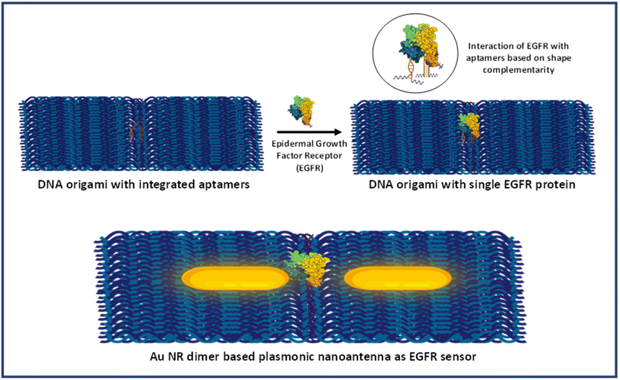 | ||
| Scheme 2 Schematic presentation of aptamer mediated immobilisation of an EGFR and Au NR dimer based plasmonic nanoantenna system for SERS based sensing. | ||
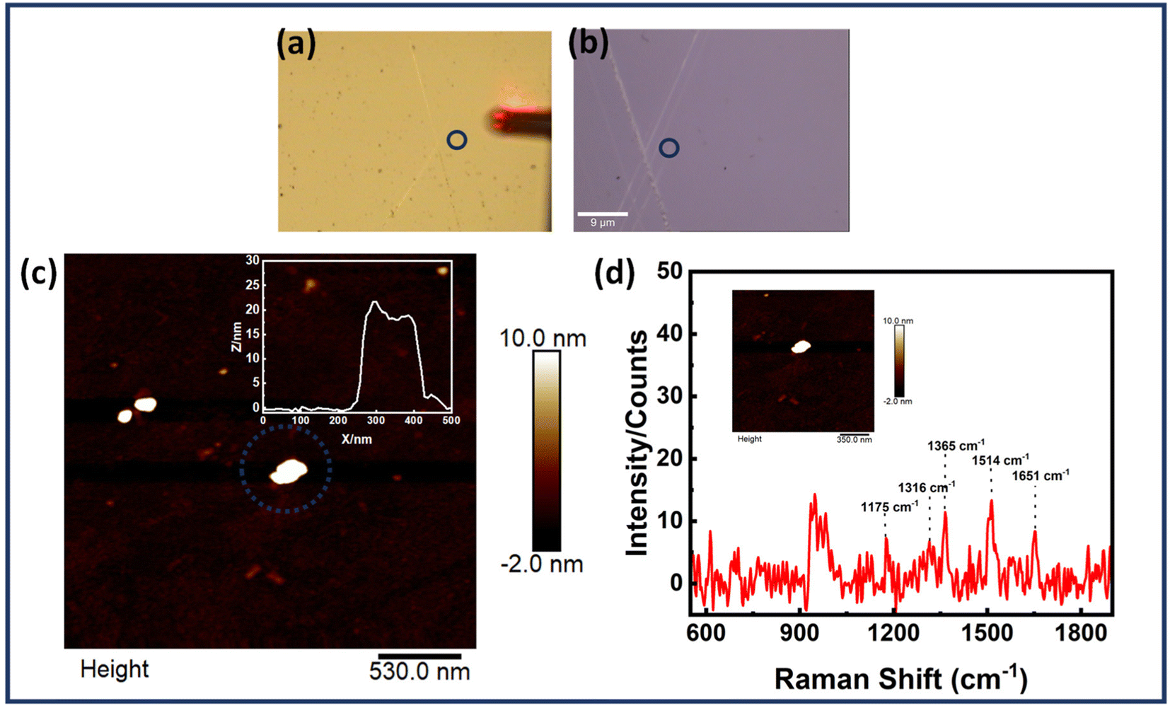 | ||
| Fig. 5 Single molecule SERS measurements of the EGFR protein immobilized in the Au NR dimer nanoantenna system, (a and b) optical images recorded using an AFM (10× objective) and confocal Raman microscope (100× objective), respectively, (c) AFM images of Au NR dimer with the corresponding height profile in the inset and (d) the corresponding SERS spectrum of an EGFR molecule with the AFM image of a single nanoantenna in presented inset. (Strategy I) The blue dotted circle represents the dimer structure probed for analysis. | ||
Moreover, to verify the identity of the Raman signal obtained as originating from the EGFR protein, reference SERS spectrum of EGFR was recorded. This was achieved by non-specifically adsorbing the protein solution (1 μM) onto Au nanoparticles deposited on a Si wafer (Fig. S12†). The resultant peaks corresponded closely with the characteristic peaks of EGFR obtained from AFM correlated SERS measurements. It must be noted that there is a slight variation in the spectral peaks obtained in the case of correlated data and reference data. These spectral modifications may be attributed to the interaction of the protein molecule with the plasmonic nanostructures and DNA origami structure.65,66 The orientation of the protein molecules relative to the nanoparticle surface affects the accessibility of specific vibrational modes to incident photons, leading to variations in the observed Raman signals.67–69 Furthermore, changes in protein conformation induced by interactions with the nanoparticle surface can also alter the vibrational modes.70 Still, there is good evidence of reproducibility in the Raman spectra attained. The minimum percentage of dimer nanoantennas giving single molecule SERS based on strategy I was estimated roughly to be ≈7–8%. Although this yield is relatively low, it is important to consider that the alignment of gold nanorod dimers and the precise gap size between them are critical factors influencing the SERS output for single EGFR proteins. Significant improvements in the alignment of DNA origami-templated nanorod dimers could enhance the field within the gap. Moreover, achieving an optimally precise nanogap is essential to balance the trade-off between a smaller gap size (which increases field enhancement but may not accommodate proteins) and a larger gap size (which accommodates proteins but significantly reduces the field). Additionally, the alignment of nanorod dimer assemblies might restrict protein accessibility to aptamers due to potential strain and misalignment of the aptamer strands.
Strategy II was also employed to obtain single molecule SERS measurements of the EGFR protein. Fig. S13† presents the AFM correlated SERS measurements for the EGFR protein bound dimer assemblies prepared following the protocol mentioned in strategy II. The SERS signals correspond closely with the reference SERS spectrum of EGFR proteins, displaying clear and discernible peaks. However, the proportion of dimer structures contributing to the SERS output using this strategy was found to be very low. In this approach, when the protein binds first with the DNA origami, it may obstruct the proper binding of the nanorods to the DNA origami. This can result in orientation defects, significantly reducing the single-molecule sensitivity of the plasmonic nanoantenna system. Therefore, for further experimentation and analysis, strategy I was used only. Also, strategy I offers better potential for use in real-time clinical settings, as it allows for the addition of biofluids containing the target biomarker to the plasmonic nanoantenna system at a later stage.
Additionally, some control measurements were also performed. Fig. S14† displays the Raman spectrum of the EGFR protein in which 1 μM protein was directly employed for Raman measurements under the same laser settings. No discernible signals were obtained. This clearly demonstrates that the anisotropic nanorod-induced plasmonic system is crucial for providing the electromagnetic field enhancements necessary to amplify the Raman signal to the single-molecule level. Furthermore, Fig. S15† shows some control measurements of DNA origami based Au NR dimer nanoantennas. Fig. S15(a)† shows the Raman spectrum of a single Au NR dimer based nanoantenna with the EGFR aptamer but without addition of EGFR. Similarly, Fig. S15(b)† shows the Raman spectrum of Au NR dimer based nanoantenna without the integrated aptamers but EGFR added to the mixture. All control SERS spectra show the appearance of no characteristic peaks of the EGFR.
Additional single-molecule SERS measurements for the EGFR protein bound to Au NR dimer-based plasmonic system are also displayed in Fig. S16 and S17.† These figures illustrate how different orientations of the dimer structure influence the single-molecule SERS of the immobilized analyte. Fig. S16† provides the AFM image of a dimer assembly which has been correlated with the FESEM image and the Raman image. In Fig. S17,† the AFM images provide an empirical understanding of the possible orientation and geometry of dimers whereas the corresponding SERS signals illustrate how the geometry affects the single molecule SERS spectrum. It is evident that the orientation of the dimer impacts the protein's accessibility for binding with the aptamer and alters the protein's orientation relative to the electromagnetic field. It has also been observed that the spectral features are extremely sensitive to the relative orientations and even a slight change in the angular orientation can significantly alter the enhancements produced.38,71
Also, time dependent SERS measurements were performed for the Au NR dimer nanoantenna system with the single EGFR protein displayed in Fig. 6. The SERS peaks remained nearly stable for up to 30 seconds, after which some peaks began to broaden (e.g., at 1653 cm−1), and a few new peaks emerged (at 1002 cm−1, 1084 cm−1, 1242 cm−1, 1665 cm−1 and 1453 cm−1). Additionally, the peaks at 1365 cm−1 and 1514 cm−1 disappeared at 30 seconds but reappeared slightly at 75 seconds. No discernible signals were found after 75 seconds except for the 942 cm−1 peak (DNA). The peak at 1002 cm−1 is related to the symmetric CC ring stretching in phenylalanine, 1084 cm−1 for the C–N bond in proteins, 1242 cm−1 for the Amide III bond, 1665 cm−1 for the Amide I/β-sheet and 1453 cm−1 for δ(C–H), δ(CH2/CH3) in proteins.72–77
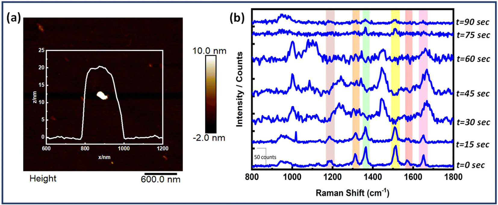 | ||
| Fig. 6 Time dependent SERS measurements of a single EGFR protein bound to Au NR dimer structure. (a) AFM image of the corresponding dimer and its height profile and, (b) SERS measurements at time intervals of 15 seconds. | ||
The fluctuations represent the behaviour of single molecules and demonstrate their interactions with the SERS substrate. The movement of the adsorbed molecule on the surface, due to photo desorption events, clearly affects the orientation of the vibrational modes. This, in turn, causes shifts in the frequency and intensity of the peaks in the single-molecule SERS spectrum.78,79
Furthermore, the effectiveness of dimer assemblies in detecting the EGFR protein at the single-molecule level across various concentrations was evaluated to determine the detection limit of the sensor system. Single-molecule SERS measurements were conducted at EGFR concentrations of 20 nM, 10 nM, 1 nM, 0.2 nM, and 20 pM. Concentration dependent SERS measurements are presented in Fig. 7. Single-molecule SERS signals were obtained down to a concentration limit of 0.2 nM. Serum levels of the EGFR protein in healthy individuals were found to be 0.326 nM, whereas, in patients with non-small cell lung cancer (NSCLC), EGFR levels were observed to be 0.231 nM.80 Thus, our detection limit (LOD) of 0.2 nM aligns well with the sensitivity required for EGFR detection in cancer diagnostics. It is noteworthy that these experiments involve the specific binding of the protein biomarker at the hotspot. Consequently, these signals correspond to single protein molecules, thereby corroborating the single-molecule sensitivity of the plasmonic nanoantenna system. However, optimizing the dimer geometry and ensuring the proper orientation of the biomarker within the hotspot volume could significantly improve the LOD, thereby enhancing the sensor system's utility for detecting various other cancer biomarkers, even when they are expressed at significantly lower levels.
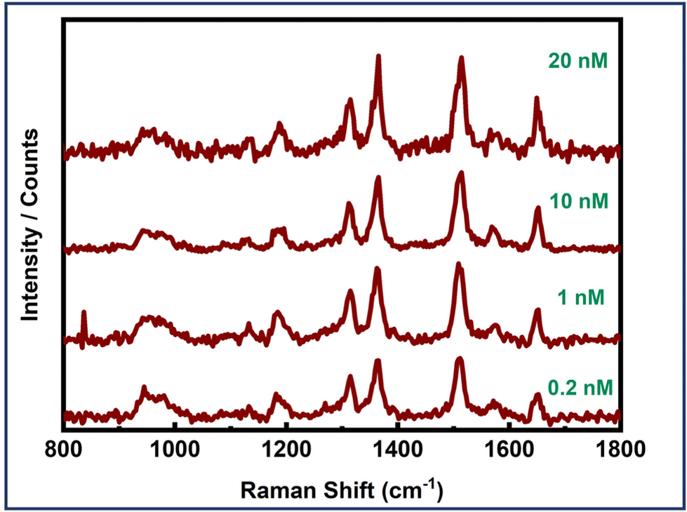 | ||
| Fig. 7 Concentration-dependent single molecule SERS measurements of an EGFR protein using Au NR dimer assemblies. | ||
Au NR monomer assemblies were also examined for single molecule detection of the protein molecule. But no clear and discernible SERS signals for the EGFR protein were obtained. Fig. S18 and S19† display the AFM correlated SERS measurements for the EGFR protein based on monomer assemblies. While signals were not detected using a single gold nanorod-based system, the use of a DNA origami-based single gold nanostar substrate might enable protein detection due to the enhanced field provided by nanostars with multiple sharp tips, as prepared in our previous studies.37,42 The SERS efficiency of a single gold nanostar surpasses that of a single gold nanorod.42 However, plasmonic coupling in gold nanorod dimers configured tip-to-tip results in highly localized energy and a notable increase in electromagnetic enhancement.81,82 For nanostar dimers also, the conformation significantly impacts performance, with coplanar tip-to-tip and tip-to-valley arrangements being more effective than nanorod dimers, whereas valley-to-tip contacts do not generate intense enhancement.83,84 Thus, for dimers, conformation is crucial in determining enhancement. Overall, when these plasmonic nanostructures are arranged in the optimal orientation, they exhibit significant potential to amplify SERS signals, achieving single-molecule sensitivity.
3.6. Study for specificity of the EGFR aptasensor
Next, the dimer assemblies were tested for their specificity and recognition capabilities. It is important to test these plasmonic platforms with some other protein molecules usually found in body fluids. Experiments were carried out following the already described strategy I, with the only modification being replacing EGFR with BSA and myoglobin. The dimer assemblies were all the same with the EGFR aptamers integrated. All other experimental parameters were kept the same for each analyte investigated. BSA is an analogue of HSA which is a very common protein in human blood with a size of 4.8 nm.37,85 On the other hand, myoglobin is a pigment containing prominent protein with the size of 3.5 nm.85Fig. 8 depicts the SERS spectra of Au NR dimer assemblies with BSA and myoglobin, revealing no discernible features apart from a peak around 950, corresponding to the peak observed solely with the DNA origami structure. This observation confirms the presence of dimer assemblies during the measurements. Fig. 8 also shows the SERS spectra of dimer assemblies tested with VEGF protein. But no peaks were obtained. These findings underscore the high selectivity and specificity capabilities of our designed plasmonic sensing template. Fig. S20–S22† depict in detail the AFM correlated SERS measurements performed for the three proteins. 150 dimer structures were probed for the EGFR protein. For BSA and myoglobin, 50 structures were investigated. For VEGF, over 30 dimer assemblies were probed.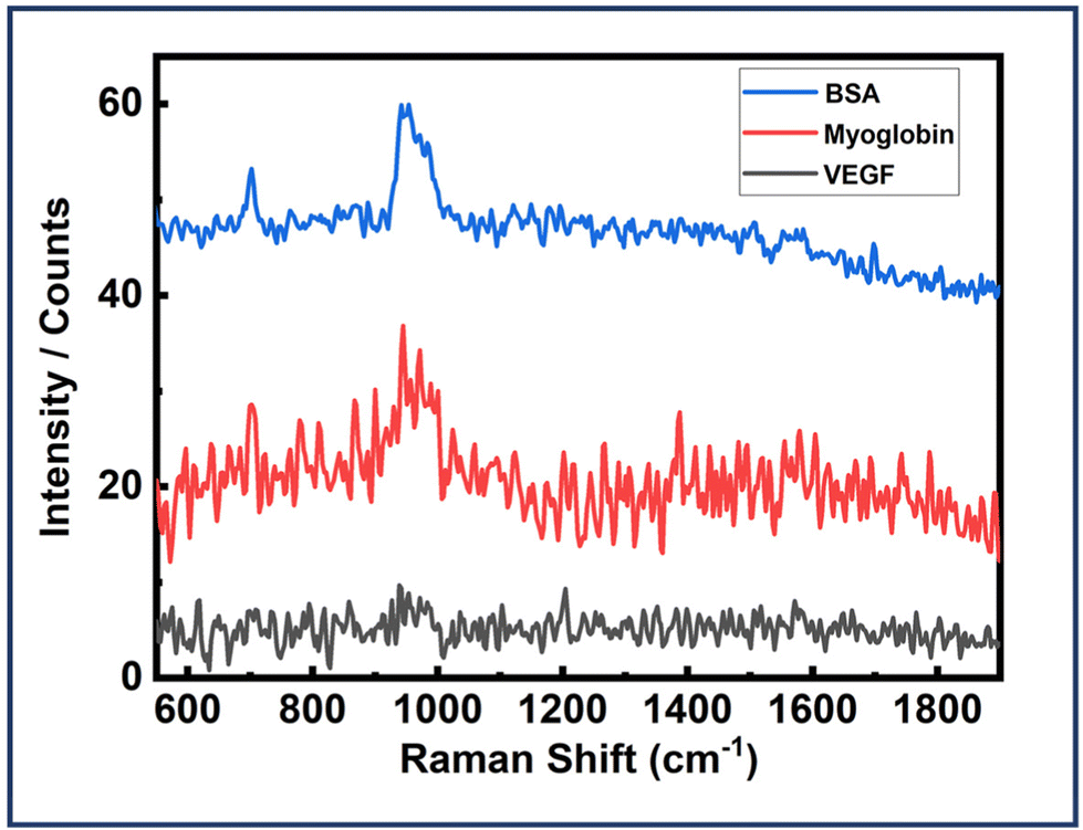 | ||
| Fig. 8 SERS spectra of Au NR dimer assemblies (EGFR aptamers integrated) with BSA, myoglobin and VEGF. | ||
4. Conclusion
Our study presents the development of a plasmonic nano-biosensor that utilizes DNA origami as a structural platform and Au NRs as active SERS materials. This combination results in the creation of a highly sensitive SERS substrate with orientation specificity and addressable hotspots. The Au NRs act as nanoantennas, creating hotspot regions with enhanced electromagnetic fields, particularly at their midpoint where plasmonic coupling occurs. This configuration provides an ideal nanogap for single protein detection using an aptamer-based approach. By correlating Raman spectroscopy with atomic force microscopy (AFM) characterization, we were able to obtain SERS signals from single epidermal growth factor receptor (EGFR) protein. The present work is the first report on label-free and specific detection of single cancerous proteins and holds great promise for ultrasensitive cancer diagnosis, potentially reducing the mortality rates. Such DNA origami-assembled nanoantenna based SERS substrates with accessible and tunable hotspots can pave the way for broader utilization of the SERS technique in single-molecule cancer diagnostics.Author contributions
T. S. devised and supervised the project. T. S. and M. S. devised the experiments, analysed the data, and wrote the manuscript. M. S. performed sample preparation, experiments, and measurements. C. K., P. S. and S. R. contributed towards measurements of samples. The manuscript was written through contributions of all authors. All authors have given approval to the final version of the manuscript.Data availability
The data supporting this article have been included as part of the ESI.†Conflicts of interest
The authors declare no conflict of interest.Acknowledgements
T. S. is thankful to the Department of Science and Technology (SERB Project-CRG/2019/005481) for financial support. M. S. is thankful to INST for a senior research fellowship. C. K. and S. R. acknowledge INST for senior research fellowships. P. S. is thankful to CSIR for a junior research fellowship.References
- K. Strimbu and J. A. Tavel, Curr. Opin. HIV AIDS, 2010, 5, 463 CrossRef PubMed.
- R. A. Alharbi, Saudi J. Biol. Sci., 2020, 27, 968–974 CrossRef CAS PubMed.
- R. S. Negm, M. Verma and S. Srivastava, Trends Mol. Med., 2002, 8, 288–293 CrossRef CAS PubMed.
- P. Carrigan and T. Krahn, New Approaches to Drug Discovery, 2016, pp. 285–311 Search PubMed.
- S. B. Nimse, M. D. Sonawane, K.-S. Song and T. Kim, Analyst, 2016, 141, 740–755 RSC.
- R. Liu, X. Ye and T. Cui, Research, 2020, 7949037 CAS.
- L. He, D. R. Tessier, K. Briggs, M. Tsangaris, M. Charron, E. M. McConnell, D. Lomovtsev and V. Tabard-Cossa, Nat. Commun., 2021, 12, 5348 CrossRef CAS PubMed.
- J. Das and S. O. Kelley, Angew. Chem., 2020, 132, 2574–2584 CrossRef.
- K. Kamagata, C. Andica, A. Kato, Y. Saito, W. Uchida, T. Hatano, M. Lukies, T. Ogawa, H. Takeshige-Amano and T. Akashi, Int. J. Mol. Sci., 2021, 22, 5216 CrossRef CAS PubMed.
- B. V. Chikkaveeraiah, A. A. Bhirde, N. Y. Morgan, H. S. Eden and X. Chen, ACS Nano, 2012, 6, 6546–6561 CrossRef CAS PubMed.
- S. Rana, A. K. Singla, A. Bajaj, S. G. Elci, O. R. Miranda, R. Mout, B. Yan, F. R. Jirik and V. M. Rotello, ACS Nano, 2012, 6, 8233–8240 CrossRef CAS PubMed.
- S. Kathiravan and J. Kanakaraj, Sci. World J., 2013, 2013, 783715 CrossRef PubMed.
- B. Asci Erkocyigit, O. Ozufuklar, A. Yardim, E. Guler Celik and S. Timur, Biosensors, 2023, 13, 387 CrossRef CAS PubMed.
- A. Borst, A. Box and A. Fluit, Eur. J. Clin. Microbiol. Infect. Dis., 2004, 23, 289–299 CrossRef CAS PubMed.
- J. Tate and G. Ward, Clin. Biochem. Rev., 2004, 25, 105 Search PubMed.
- K. Krupa and M. Bekiesińska-Figatowska, Pol. J. Radiol., 2015, 80, 93 CrossRef PubMed.
- K. Dodo, K. Fujita and M. Sodeoka, J. Am. Chem. Soc., 2022, 144, 19651–19667 CrossRef CAS PubMed.
- E. C. Le Ru and P. G. Etchegoin, Annu. Rev. Phys. Chem., 2012, 63, 65–87 CrossRef CAS PubMed.
- A. Bonifacio, in Principles and Clinical Diagnostic Applications of Surface-Enhanced Raman Spectroscopy, Elsevier, 2022, pp. 125–170 Search PubMed.
- Q. Wei, Q. Dong and H. Pu, Biosensors, 2023, 13, 296 CrossRef CAS PubMed.
- U. Azhar, Q. Ahmed, S. Ishaq, Z. T. Alwahabi and S. Dai, Biosensors, 2022, 12, 121 CrossRef CAS PubMed.
- J. Plou, P. S. Valera, I. Garcia, C. D. de Albuquerque, A. Carracedo and L. M. Liz-Marzan, ACS Photonics, 2022, 9, 333–350 CrossRef CAS PubMed.
- J. Langer, D. Jimenez de Aberasturi, J. Aizpurua, R. A. Alvarez-Puebla, B. Auguié, J. J. Baumberg, G. C. Bazan, S. E. Bell, A. Boisen and A. G. Brolo, ACS Nano, 2019, 14, 28–117 CrossRef PubMed.
- T. Itoh, M. Procházka, Z.-C. Dong, W. Ji, Y. S. Yamamoto, Y. Zhang and Y. Ozaki, Chem. Rev., 2023, 123, 1552–1634 CrossRef CAS PubMed.
- J. Reguera, J. Langer, D. J. de Aberasturi and L. M. Liz-Marzán, Colloidal Synth. Plasmonic Nanomet., 2020, 713–754 CAS.
- E. C. Le Ru, E. Blackie, M. Meyer and P. G. Etchegoin, J. Phys. Chem. C, 2007, 111, 13794–13803 CrossRef CAS.
- W. Lee, B.-H. Kang, H. Yang, M. Park, J. H. Kwak, T. Chung, Y. Jeong, B. K. Kim and K.-H. Jeong, Nat. Commun., 2021, 12, 159 CrossRef CAS PubMed.
- Y. Zhou, J. Liu, T. Zheng and Y. Tian, Anal. Chem., 2020, 92, 5910–5920 CrossRef CAS PubMed.
- S. Simoncelli, E.-M. Roller, P. Urban, R. Schreiber, A. J. Turberfield, T. Liedl and T. Lohmüller, ACS Nano, 2016, 10, 9809–9815 CrossRef CAS PubMed.
- P. G. Etchegoin and E. C. Le Ru, Phys. Chem. Chem. Phys., 2008, 10, 6079–6089 RSC.
- L. M. Almehmadi, S. M. Curley, N. A. Tokranova, S. A. Tenenbaum and I. K. Lednev, Sci. Rep., 2019, 9, 12356 CrossRef PubMed.
- M. Dass, F. N. Gür, K. Kołątaj, M. J. Urban and T. Liedl, J. Phys. Chem. C, 2021, 125, 5969–5981 CrossRef CAS PubMed.
- F. Hong, F. Zhang, Y. Liu and H. Yan, Chem. Rev., 2017, 117, 12584–12640 CrossRef CAS PubMed.
- P. Zhan, A. Peil, Q. Jiang, D. Wang, S. Mousavi, Q. Xiong, Q. Shen, Y. Shang, B. Ding and C. Lin, Chem. Rev., 2023, 123, 3976–4050 CrossRef CAS PubMed.
- K. Tapio, A. Mostafa, Y. Kanehira, A. Suma, A. Dutta and I. Bald, ACS Nano, 2021, 15, 7065–7077 CrossRef CAS PubMed.
- C. Heck, Y. Kanehira, J. Kneipp and I. Bald, Angew. Chem., Int. Ed., 2018, 57, 7444–7447 CrossRef CAS PubMed.
- S. Tanwar, V. Kaur, G. Kaur and T. Sen, J. Phys. Chem. Lett., 2021, 12, 8141–8150 CrossRef CAS PubMed.
- F. Schuknecht, K. Kołątaj, M. Steinberger, T. Liedl and T. Lohmueller, Nat. Commun., 2023, 14, 7192 CrossRef CAS PubMed.
- H. Shin, S. Oh, D. Kang and Y. Choi, Adv. Sci., 2020, 7, 1903638 CrossRef CAS PubMed.
- L.-J. Xu, C. Zong, X.-S. Zheng, P. Hu, J.-M. Feng and B. Ren, Anal. Chem., 2014, 86, 2238–2245 CrossRef CAS PubMed.
- S. Sigismund, D. Avanzato and L. Lanzetti, Mol. Oncol., 2018, 12, 3–20 CrossRef PubMed.
- S. Tanwar, K. K. Haldar and T. Sen, J. Am. Chem. Soc., 2017, 139, 17639–17648 CrossRef CAS PubMed.
- X. Lan, Z. Chen, G. Dai, X. Lu, W. Ni and Q. Wang, J. Am. Chem. Soc., 2013, 135, 11441–11444 CrossRef CAS PubMed.
- S. Pal, Z. Deng, H. Wang, S. Zou, Y. Liu and H. Yan, J. Am. Chem. Soc., 2011, 133, 17606–17609 CrossRef CAS PubMed.
- M. B. Mohamed, V. Volkov, S. Link and M. A. El-Sayed, Chem. Phys. Lett., 2000, 317, 517–523 CrossRef CAS.
- G. Haran and L. Chuntonov, Chem. Rev., 2018, 118, 5539–5580 CrossRef CAS PubMed.
- A. Kinkhabwala, Z. Yu, S. Fan, Y. Avlasevich, K. Müllen and W. Moerner, Nat. Photonics, 2009, 3, 654–657 CrossRef CAS.
- T. Hermann and D. J. Patel, Science, 2000, 287, 820–825 CrossRef CAS PubMed.
- T. Sakamoto, E. Ennifar and Y. Nakamura, Biochimie, 2018, 145, 91–97 CrossRef CAS PubMed.
- M. Rimmele, ChemBioChem, 2003, 4, 963–971 CrossRef CAS PubMed.
- D.-L. Wang, Y.-L. Song, Z. Zhu, X.-L. Li, Y. Zou, H.-T. Yang, J.-J. Wang, P.-S. Yao, R.-J. Pan and C. J. Yang, Biochem. Biophys. Res. Commun., 2014, 453, 681–685 CrossRef CAS PubMed.
- N. Li, H. H. Nguyen, M. Byrom and A. D. Ellington, PLoS One, 2011, 6, e20299 CrossRef CAS PubMed.
- A. Anandita, D. S. Sharma, N. Singh, R. K. Singh, V. Sharma and D. Rath, in Enzyme-based Biosensors: Recent Advances and Applications in Healthcare, Springer, 2024, pp. 79–107 Search PubMed.
- H. Li, S. Xing, J. Xu, Y. He, Y. Lai, Y. Wang, G. Zhang, S. Guo, M. Deng and M. Zeng, Talanta, 2021, 221, 121670 CrossRef CAS PubMed.
- M. P. Melancon, M. Zhou, R. Zhang, C. Xiong, P. Allen, X. Wen, Q. Huang, M. Wallace, J. N. Myers and R. J. Stafford, ACS Nano, 2014, 8, 4530–4538 CrossRef CAS PubMed.
- X. Xie, H. Nie, Y. Zhou, S. Lian, H. Mei, Y. Lu, H. Dong, F. Li, T. Li and B. Li, Nat. Commun., 2019, 10, 5476 CrossRef CAS PubMed.
- J. Wu, Z. Lin, Z. Zou, S. Liang, M. Wu, T. Y. Hu and Y. Zhang, J. Am. Chem. Soc., 2022, 144, 23483–23491 CrossRef CAS PubMed.
- M. Liu and P. Guyot-Sionnest, J. Phys. Chem. B, 2005, 109, 22192–22200 CrossRef CAS PubMed.
- L. C. Zanetti-Domingues, D. Korovesis, S. R. Needham, C. J. Tynan, S. Sagawa, S. K. Roberts, A. Kuzmanic, E. Ortiz-Zapater, P. Jain, R. C. Roovers, A. Lajevardipour, P. M. P. van Bergen en Henegouwen, G. Santis, A. H. A. Clayton, D. T. Clarke, F. L. Gervasio, Y. Shan, D. E. Shaw, D. J. Rolfe, P. J. Parker and M. L. Martin-Fernandez, Nat. Commun., 2018, 9, 4325 CrossRef PubMed.
- A. R. Goldfarb and L. J. Saidel, Science, 1951, 114, 156–157 CrossRef CAS PubMed.
- M. Keshavarz, P. Kassanos, B. Tan and K. Venkatakrishnan, Nanoscale Horiz., 2020, 5, 294–307 RSC.
- N. Kuhar, S. Sil and S. Umapathy, Spectrochim. Acta, Part A, 2021, 258, 119712 CrossRef CAS PubMed.
- Y.-M. Shen, M.-Y. Gao, X. Chen, A.-G. Shen and J.-M. Hu, Spectrochim. Acta, Part A, 2021, 252, 119566 CrossRef CAS PubMed.
- D. Lazaro-Pacheco, A. M. Shaaban, S. Rehman and I. Rehman, Appl. Spectrosc. Rev., 2020, 55, 439–475 CrossRef.
- C. Zong, M. Xu, L.-J. Xu, T. Wei, X. Ma, X.-S. Zheng, R. Hu and B. Ren, Chem. Rev., 2018, 118, 4946–4980 CrossRef CAS PubMed.
- L. A. Dick, A. J. Haes and R. P. Van Duyne, J. Phys. Chem. B, 2000, 104, 11752–11762 CrossRef CAS.
- E. S. Grabbe and R. P. Buck, J. Am. Chem. Soc., 1989, 111, 8362–8366 CrossRef CAS.
- S. Keskin and M. Çulha, Analyst, 2012, 137, 2651–2657 RSC.
- T. Cedervall, I. Lynch, S. Lindman, T. Berggård, E. Thulin, H. Nilsson, K. A. Dawson and S. Linse, Proc. Natl. Acad. Sci. U. S. A., 2007, 104, 2050–2055 CrossRef CAS PubMed.
- M. Feng and H. Tachikawa, J. Am. Chem. Soc., 2008, 130, 7443–7448 CrossRef CAS PubMed.
- S. K. Pal, H. Chatterjee and S. K. Ghosh, RSC Adv., 2019, 9, 42145–42154 RSC.
- B. Fazio, C. D'Andrea, A. Foti, E. Messina, A. Irrera, M. G. Donato, V. Villari, N. Micali, O. M. Maragò and P. G. Gucciardi, Sci. Rep., 2016, 6, 26952 CrossRef CAS PubMed.
- G. P. Szekeres and J. Kneipp, Front. Chem., 2019, 7, 30 CrossRef CAS PubMed.
- V. Lin and J. Koenig, Biopolymers, 1976, 15, 203–218 CrossRef CAS PubMed.
- A. Rygula, K. Majzner, K. M. Marzec, A. Kaczor, M. Pilarczyk and M. Baranska, J. Raman Spectrosc., 2013, 44, 1061–1076 CrossRef CAS.
- T. D. Payne, S. J. Klawa, T. Jian, Q. Wang, S. H. Kim, R. Freeman and Z. D. Schultz, Sens. Diagn., 2023, 2, 1483–1491 RSC.
- S. Aitekenov, A. Sultangaziyev, A. Ilyas, A. Dyussupova, A. Boranova, A. Gaipov and R. Bukasov, Sens. Bio-Sens. Res., 2022, 38, 100535 CrossRef.
- A. Weiss and G. Haran, J. Phys. Chem. B, 2001, 105, 12348–12354 CrossRef CAS.
- P. G. Etchegoin and E. C. Le Ru, Anal. Chem., 2010, 82, 2888–2892 CrossRef CAS PubMed.
- Y. Lemos-Gonzalez, F. Rodriguez-Berrocal, O. Cordero, C. Gomez and M. Páez De La Cadena, Br. J. Cancer, 2007, 96, 1569–1578 CrossRef CAS PubMed.
- L. Shao, K. C. Woo, H. Chen, Z. Jin, J. Wang and H.-Q. Lin, ACS Nano, 2010, 4, 3053–3062 CrossRef CAS PubMed.
- L. S. Slaughter, Y. Wu, B. A. Willingham, P. Nordlander and S. Link, ACS Nano, 2010, 4, 4657–4666 CrossRef CAS PubMed.
- D. M. Solís, J. M. Taboada, F. Obelleiro, L. M. Liz-Marzán and F. J. García de Abajo, ACS Photonics, 2017, 4, 329–337 CrossRef PubMed.
- D. M. Solís, J. M. Taboada, F. Obelleiro, L. M. Liz-Marzán and F. J. García de Abajo, ACS Nano, 2014, 8, 7559–7570 CrossRef PubMed.
- N. E. Kaufman, S. Dhingra, S. D. Jois and M. D. G. H. Vicente, Molecules, 2021, 26, 1076 CrossRef CAS PubMed.
Footnote |
| † Electronic supplementary information (ESI) available. See DOI: https://doi.org/10.1039/d4nr01110d |
| This journal is © The Royal Society of Chemistry 2024 |