
 Open Access Article
 This Open Access Article is licensed under a
 Creative Commons Attribution 3.0 Unported Licence
Understanding electrochemical properties of supported lipid bilayers interfaced with organic electronic devices†
Zixuan
Lu
 a,
Douglas
van Niekerk
a,
Achileas
Savva
a,
Konstantinos
Kallitsis
a,
Quentin
Thiburce
b,
Alberto
Salleo
b,
Anna-Maria
Pappa
*acd and
Róisín M.
Owens
*a
a,
Douglas
van Niekerk
a,
Achileas
Savva
a,
Konstantinos
Kallitsis
a,
Quentin
Thiburce
b,
Alberto
Salleo
b,
Anna-Maria
Pappa
*acd and
Róisín M.
Owens
*a
aDepartment of Chemical Engineering and Biotechnology, University of Cambridge, Cambridge CB3 0AS, UK. E-mail: rmo37@cam.ac.uk
bDepartment of Materials Science and Engineering, Stanford University, Stanford, California 94305, USA
cHealthcare Innovation Engineering Center, Khalifa University, Abu Dhabi, United Arab Emirates. E-mail: anna.pappa@ku.ac.ae
dDepartment of Biomedical Engineering, Khalifa University of Science and Technology, PO BOX 127788, Abu Dhabi, United Arab Emirates
First published on 3rd May 2022
Abstract
Supported lipid bilayers (SLBs) are cell–membrane-mimicking platforms of varying biological complexity, that can be formed on solid surfaces and used to characterise the properties of the plasma membrane or to study membrane interactions at the molecular level. The incorporation of microfabricated electrodes and transistors has allowed for their electrochemical characterisation using techniques such as Electrochemical Impedance Spectroscopy (EIS) and transistor-based impedance spectroscopy. In this work, we combine experimental data with numerical simulation to explore the relationship between changes in SLB quality and impedance output, delving into a deeper understanding of the impedance profiles of devices with and without SLB, as well as extracted parameters such as membrane resistance (Rm). We extrapolate this approach to investigate the relationship between microelectrode area and sensor sensitivity to changes in SLB state, towards rational device design. We highlight the trend of electrode size (polymer volume) required for sensing bilayer presence as well as the dependence of the electrode sensitivity to the SLB capacitance and resistance. Finally, we illustrate how our flexible approach of including electrode and transistor measurements to amalgamate characteristic impedance spectra of transistors, overcomes the problem of low frequency noise and errors seen with traditional EIS.
Introduction
More than half of currently approved drugs target the cell membrane.1 However, the complexity and slow turnaround of traditional cell-based assays make the study of molecular interactions with the cell membrane quite challenging. As an alternative to whole cells, supported lipid bilayers (SLBs), first introduced by Tamm et al.,2 have been proposed as a simple and representative cell membrane model to either characterize the properties of the plasma membrane or to study interactions at the molecular level. The compatibility of SLBs with surface-sensitive analytical techniques, including quartz crystal microbalance,3 fluorescence microscopy,4 and atomic force microscopy5 has allowed their characterization and the development of functional assays. Typically, SLBs are formed on glass6 or mica7 as they are both hydrophilic and smooth, hence facilitating the spontaneous fusion of vesicles. In terms of biomimicry, the compositional complexity of SLBs has increased over the years, for example through the addition of reconstituted proteins.8 Recently, SLBs made from cell-derived material (extracellular vesicles) have been used to form native lipid bilayers via vesicle fusion. These “authentic” bilayers exhibit the biological complexity of the cell membrane.9–11Poly(3,4-ethylenedioxythiophene) polystyrene sulfonate (PEDOT:PSS), is a polymer mixture made from PEDOT and PSS. PEDOT is a polythiophene-based conjugated polymer that carries positive charges while the sulfonyl groups of PSS are deprotonated and carry a negative charge. PEDOT:PSS-based devices, mainly organic electrodes and organic electrochemical transistors (OECTs), exhibit superior performance compared to inorganic counterparts for interfacing and transducing biological signals.12,13 Organic microelectrodes are simply structured with PEDOT:PSS coating on top of metal electrodes. The PEDOT:PSS coating lowers the device impedance at the interface between the ionic and electronic domains, compared to plain metal electrodes (of the same area), reducing the baseline noise, increasing device Signal to Noise Ratio (SNR), hence the sensitivity to changes in a given biological system.14 OECTs, which are three-terminal (source, drain, gate) devices, where the conductivity of the PEDOT:PSS channel between the source and drain can be modulated by the gate-injected ionic current, can transduce biological events with high sensitivity given by their record transconductance values.12
Electrochemical Impedance spectroscopy (EIS), when used for SLB characterization, records the impedance of an SLB by applying a sinusoidal voltage at a range of frequencies. As SLBs have both resistive and capacitive properties, and these properties have unique frequency-dependent behaviours, the evolution of the net impedance with frequency provides information on the time constants of the physical processes within the system.18,24 EIS has been extensively used for the characterization of SLBs including those formed on PEDOT:PSS electrodes.19 Such studies have primarily focused on understanding the electrochemical properties of SLBs and their interactions with the external environment using experimental data. In this work we aim to gain a deeper understanding on the EIS data combining in silico and experimental data.
To infer the properties of the membrane using EIS, the parameters of equivalent electric circuits are estimated using regression, which allows quantification of the state of the SLB at the time of measurement.16,17 Less commonly, the inverse of this relationship may be interrogated; by choosing the parameter values for an equivalent electric circuit which models the system (SLB and electrode), the (ideal) output of the system which fits these values can be generated. By varying the parameter values which correspond to SLB state, the variation in the sensor output can be simulated, yielding a deterministic input–output relation. This practice allows for greater interpretability of the sensor output (and thus fluctuations in the nature of the SLB) and improved accuracy in estimating SLB state quantities. Hoiles et al.18 and Valincius et al.19,20 for example, examine the impact of changes in tethered lipid bilayer state and defect formation on sensor output, respectively. Such models have been under-utilized, however, in synthesizing sensor output as a function of variations in device-related parameters, such as geometry and material properties. Combining such simulations with perturbations in the SLB state allow for the sensitivity of the sensor to be determined as a function of device properties (for specific applications). This, in turn, allows for rational design of devices, motivated by sensor performance, such as sensitivity and linearity, as opposed to solely convenience or compatibility with the biological sample under test. A prominent example of such an approach in OECTs is given by Nissa et al.21 Further, Faria et al. had investigated the trend of OECT channel sizes on the sensitivity of a black lipid bilayer, suggesting micro-sized OECT channels are more sensitive to detect leaky (low impedance) bilayers than macro-sized ones.22 Also, Koutsouras et al. have investigated the effect of PEDOT:PSS-electrode sizes on the sensing of cell layer barrier models, identifying the critical electrode size after which effective sensing of a barrier layer becomes possible.15
Herein, we combine experimental and in silico methods to better understand SLB characteristics (both all-lipid and cell–membrane derived lipid bilayers) and calibrate how changes in the SLB manifest in the sensor output. We also employ a simple functional assay using a pore-forming toxin to correlate our findings with the observed changes in the measured impedance. Further, we investigate the optimal design criteria for measurements of SLBs using PEDOT:PSS microelectrodes. Finally, by employing a technique previously proposed for use in barrier tissue monitoring,23 we demonstrate a means of amalgamating EIS and OECT measurement data, taking advantage of their mutually exclusive noise profiles, to yield an impedance measurement with improved SNR across the measured frequency interval.
Results and discussion
Experimental and in silico understanding of SLB properties measured via EIS
In this work we study the properties of both naturally-derived SLBs as well as all-lipid SLBs (Fig. 1a).24 As shown in previous studies, naturally-derived (native) bilayers exhibit lower resistance (sealing) values due to differences in the lipid packing and the existence of transmembrane proteins which introduces defects and hence more ionic transport paths.17 For the all-lipid membranes, 4![[thin space (1/6-em)]](https://www.rsc.org/images/entities/char_2009.gif) :1 mixtures of 1,2-dioleoyl-sn-glycero-3-phosphocholine (DOPC) and 1,2-dioleoyl-3-trimethylammonium-propane (DOTAP) are used. The positive charge of DOTAP facilitates electrostatic attractions with the negatively charged PSS, which greatly helps the fusion of the liposome and formation of a high-quality (high membrane resistance) bilayer.16,17 Thus, DOPC:DOTAP SLB is used as a model to understand the electronic properties of the SLB in a controlled setting. The all-lipid SLB is formed on microelectrodes via vesicle (around 100 nm in diameter) fusion (Fig. S1, ESI†). After the formation of the SLB on a PEDOT:PSS coated microelectrode, EIS is used to characterise the membrane properties, using Ag/AgCl and Pt electrodes as reference and counter electrodes, respectively. EIS is performed by applying a voltage, which induces ion flux in the system, transduced in the PEDOT:PSS into electron flux, which is the current measured by the potentiostat. The equivalent circuit used to describe the system is shown in Fig. 1a, and is in line with previous studies forming SLBs on PEDOT:PSS microelectrodes.16,17 The equivalent circuit is used to model the SLB-PEDOT:PSS system by identifying how each component of the system contributes to the overall voltage–current relationship. Here, a parallel circuit of membrane resistance (Rm) and capacitance (Cm) representing the membrane, is connected in series with the electrolyte resistance (Re) and the capacitance (Cp) of PEDOT:PSS. The baseline (black curve) is characterised by a downward slope at low frequency in the impedance magnitude and a swing in (negative) phase from approximately 90° to 0°, characteristic of an (almost) pure capacitance (Fig. 1b and c). The formation of the membrane results in a noticeable shift relative to the baseline spectrum of pristine PEDOT:PSS electrodes as shown in the Bode (impedance and phase) plots. Note, the device operates by transducing changes in accumulation of charges in the conducting polymer due to the presence or absence of the membrane (of varying degrees of quality), rather than by reporting reactions on the surface of the electrodes. The addition of the membrane to the system introduces an additional time constant; practically, the step response of the system will be dictated by the combination of the time required to charge the PEDOT:PSS layer (via the electrolyte) and the time required to accumulate charge on the membrane surface, while charge ‘leaks’ through the membrane resistance. This time constant is clearly seen in the Bode plot as a plateau in the impedance magnitude and a peak in the phase (or alternatively as a semicircle in the Nyquist plot; Fig. S2, ESI†). In the impedance magnitude vs. frequency plot (orange and green curves in Fig. 1b), a downward slope (or “roll-off”) at high frequency represents the frequency region where the capacitive nature of the SLB dominates, whereas a plateau connecting the capacitive region at lower frequency (the PEDOT:PSS capacitance) to the capacitive region of the SLB, represents the region where the SLB resistance dominates.25 In comparison, a native SLB (from human embryonic kidney (HEK 293) cells; Fig. 1b and c), demonstrates a lower resistance plateau than the all-lipid SLB, resulting from defects in the membrane (e.g. transmembrane proteins) as well as a looser packing of the lipids.16,17 The lower membrane resistance corresponds to a smaller (faster) time constant, which can be seen as a shift in the phase peak towards higher frequencies. The Nyquist plot (Fig. S2, ESI†) displays the real and imaginary part of the impedance, and by fitting data points of the Nyquist plot with the model circuit, the Rm values can be extracted confirming the higher membrane resistance of the all-lipid SLB compared to the native one. The calculated resistance values (Fig. S3, ESI†) of the DOPC:DOTAP SLBs are found to be around 72.0 ± 19.8 Ω cm2 which is about one order of magnitude higher compared to the resistance of the native HEK293 SLBs found to be 6.6 ± 1.1 Ω cm2.
:1 mixtures of 1,2-dioleoyl-sn-glycero-3-phosphocholine (DOPC) and 1,2-dioleoyl-3-trimethylammonium-propane (DOTAP) are used. The positive charge of DOTAP facilitates electrostatic attractions with the negatively charged PSS, which greatly helps the fusion of the liposome and formation of a high-quality (high membrane resistance) bilayer.16,17 Thus, DOPC:DOTAP SLB is used as a model to understand the electronic properties of the SLB in a controlled setting. The all-lipid SLB is formed on microelectrodes via vesicle (around 100 nm in diameter) fusion (Fig. S1, ESI†). After the formation of the SLB on a PEDOT:PSS coated microelectrode, EIS is used to characterise the membrane properties, using Ag/AgCl and Pt electrodes as reference and counter electrodes, respectively. EIS is performed by applying a voltage, which induces ion flux in the system, transduced in the PEDOT:PSS into electron flux, which is the current measured by the potentiostat. The equivalent circuit used to describe the system is shown in Fig. 1a, and is in line with previous studies forming SLBs on PEDOT:PSS microelectrodes.16,17 The equivalent circuit is used to model the SLB-PEDOT:PSS system by identifying how each component of the system contributes to the overall voltage–current relationship. Here, a parallel circuit of membrane resistance (Rm) and capacitance (Cm) representing the membrane, is connected in series with the electrolyte resistance (Re) and the capacitance (Cp) of PEDOT:PSS. The baseline (black curve) is characterised by a downward slope at low frequency in the impedance magnitude and a swing in (negative) phase from approximately 90° to 0°, characteristic of an (almost) pure capacitance (Fig. 1b and c). The formation of the membrane results in a noticeable shift relative to the baseline spectrum of pristine PEDOT:PSS electrodes as shown in the Bode (impedance and phase) plots. Note, the device operates by transducing changes in accumulation of charges in the conducting polymer due to the presence or absence of the membrane (of varying degrees of quality), rather than by reporting reactions on the surface of the electrodes. The addition of the membrane to the system introduces an additional time constant; practically, the step response of the system will be dictated by the combination of the time required to charge the PEDOT:PSS layer (via the electrolyte) and the time required to accumulate charge on the membrane surface, while charge ‘leaks’ through the membrane resistance. This time constant is clearly seen in the Bode plot as a plateau in the impedance magnitude and a peak in the phase (or alternatively as a semicircle in the Nyquist plot; Fig. S2, ESI†). In the impedance magnitude vs. frequency plot (orange and green curves in Fig. 1b), a downward slope (or “roll-off”) at high frequency represents the frequency region where the capacitive nature of the SLB dominates, whereas a plateau connecting the capacitive region at lower frequency (the PEDOT:PSS capacitance) to the capacitive region of the SLB, represents the region where the SLB resistance dominates.25 In comparison, a native SLB (from human embryonic kidney (HEK 293) cells; Fig. 1b and c), demonstrates a lower resistance plateau than the all-lipid SLB, resulting from defects in the membrane (e.g. transmembrane proteins) as well as a looser packing of the lipids.16,17 The lower membrane resistance corresponds to a smaller (faster) time constant, which can be seen as a shift in the phase peak towards higher frequencies. The Nyquist plot (Fig. S2, ESI†) displays the real and imaginary part of the impedance, and by fitting data points of the Nyquist plot with the model circuit, the Rm values can be extracted confirming the higher membrane resistance of the all-lipid SLB compared to the native one. The calculated resistance values (Fig. S3, ESI†) of the DOPC:DOTAP SLBs are found to be around 72.0 ± 19.8 Ω cm2 which is about one order of magnitude higher compared to the resistance of the native HEK293 SLBs found to be 6.6 ± 1.1 Ω cm2.
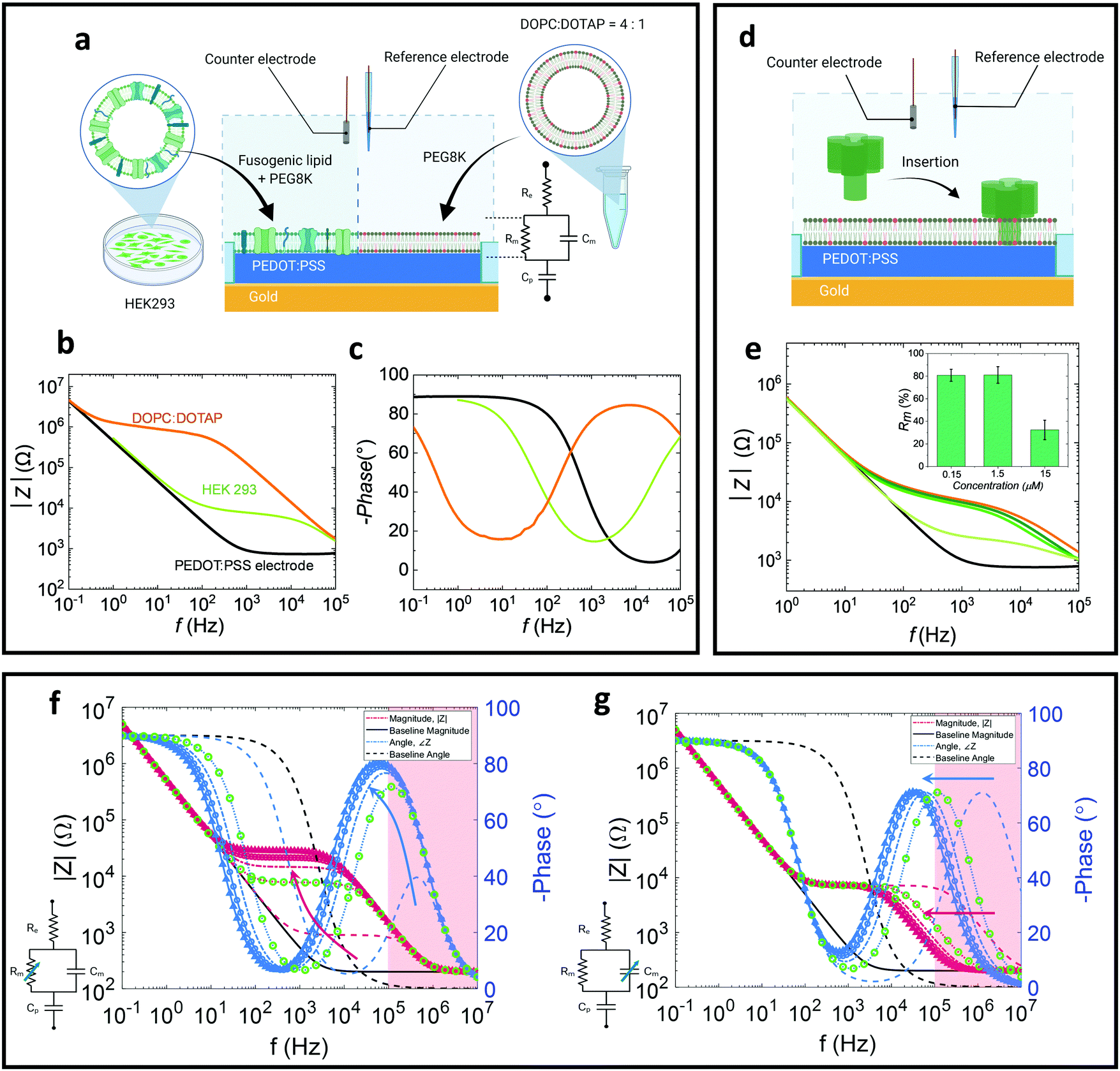 | ||
| Fig. 1 (a)–(c) EIS measurement of native and all-lipid SLBs: (a) illustration of concept to integrate the native HEK 293 and DOPC:DOTAP SLBs onto PEDOT:PSS coated microelectrode (circular electrode with 450 μm diameter) with corresponding (b) Bode plot (c) phase plot (black: electrode baseline, green: HEK293 SLB, and orange: DOPC:DOTAP SLB). (d) Schematic representation of the interaction of α-HL with our all-lipid membrane on microelectrodes (450 μm diameter). (e) Bode plot showing dose dependent (n = 4) monitoring of SLB–α-HL interactions at 37 °C (black and orange curves are the impedance spectra for bare electrode and electrode with all-lipid SLB, respectively. The 0.15 μM, 1.5 μM, and 15 μM α-HL dose–response curves are presented by green curves with dark to light shades, respectively) and calculated % Rm change for the various a-HL concentrations tested (inset). (f) and (g) Simulated impedance spectra with respect to changes of membrane characteristics relative to the fitted HEK293 SLB impedance (Cp = 2 μF, Re = 200 Ω). Impedance magnitude is plotted in magenta and phase in blue. Red regions indicate regions above the measurement capabilities of the instruments used. Arrows indicate the direction of increasing size of the parameter of interest. Green circles indicate the impedance spectra which correspond with the HEK293 SLB impedance. (f) System impedance change as a function of the membrane resistance, Rm = {0.1–4} × 7 kΩ; (g) System impedance change as a function of membrane capacitance, Cm = {0.1–4} × 7 nF. | ||
A prototypical pore-forming toxin, alpha-hemolysin26 (α-HL) was administered to the all-lipid SLB (Fig. 1d) system as a functional assay. Typically, α-HL, upon binding to the cell surface, inserts into the membrane, forming an oligomeric transmembrane pore from which ions (e.g. Ca2+, K+), ATP, and small molecular weight molecules can pass through, and at high doses, can cause cell lysis.27 This functional assay was carried out at 37 °C, thus the impact of increasing temperature on the EIS profiles of the SLB (without addition of the pore-forming toxin) was evaluated (Fig. S5, ESI†). However, only a small decrease in impedance was observed within 1 hour of incubation at room temperature or 37 °C. At low concentrations of α-HL (0.15 μM and 1.5 μM; following a 10 minute incubation) we observe small changes in the recorded resistance, indicated by slight changes in plateau height, as well as a capacitance increase, indicated by the left-shift of the impedance knee and slope at high frequencies (104–105 Hz) (Fig. 1e). This could be attributed to the initial insertion of α-HL prior to oligomerisation,26 resulting a small resistance change. At higher concentrations of α-HL (15 μM), we observed a drastic decline in the plateau height (Fig. 2e) accompanied by a decrease in the semicircle diameter in the Nyquist plot (Fig. S4, ESI†). The decrease in Rm is consistent with a leakier SLB, with more paths for ions to transit through the membrane, as a result of the pore formation by α-HL insertion and oligomerisation.
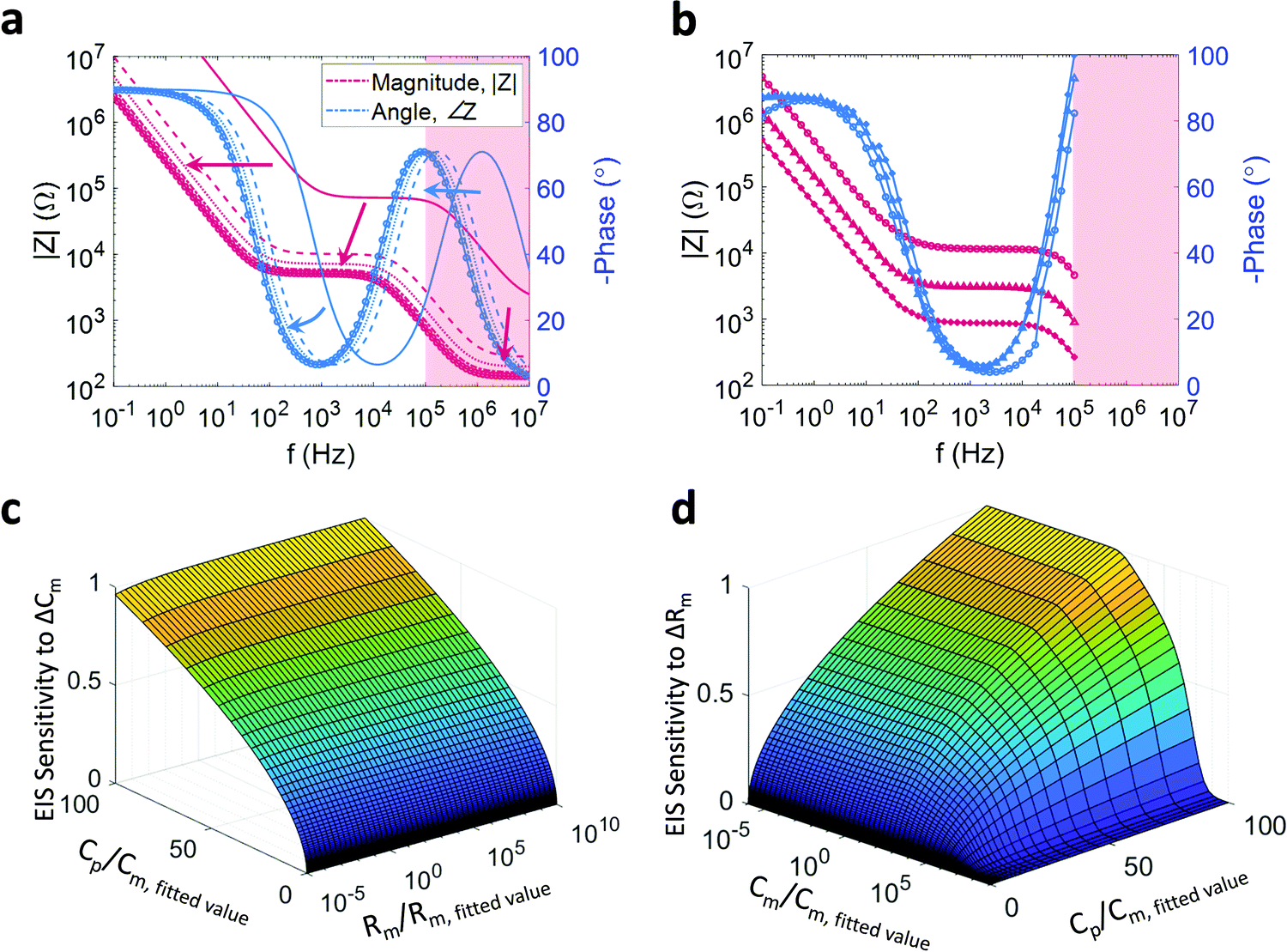 | ||
| Fig. 2 (a) and (b) Impact of geometry on device sensitivity: (a) impedance spectra as a function of changing PEDOT:PSS cross sectional area, which modulates the PEDOT:PSS volume, and therefore the PEDOT:PSS capacitance, as well as the electrolyte resistance. Cp = {0.01–2} × 2 μF, Re = (283 mΩ F)/Cp. Arrows indicate the direction of increasing PEDOT:PSS surface area. (b) Experimental data of impedance and phase with different shaped electrodes (cross: 0.0204 cm2; square: 0.0113 cm2; circle: 0.0028 cm2). Impedance is plotted in magenta, and phase is plotted in blue; (c) and (d) normalised EIS sensitivity to changes in Cm (Rm) as a function of PEDOT:PSS electrode size (where Cp is used as a proxy) and Rm (Cm) with Re = (283 mΩ F)/Cp. The sensitivity is evaluated at Cp = {10−6–100} × Cm,fitted where Cm,fitted = 7 nF. The sensitivity is calculated as the 1-norm of the change in the admittance due to a change in Cm (Rm). (c) The sensitivity of the EIS measurement to changes in Cm, where ΔCm is in the range {10−3–10} × Cm,fitted where Cm,fitted = 7 nF. The sensitivity is evaluated over the stated range in Cp, as well as over the range Rm = {10−5–105} × Rm,fitted where Rm,fitted = 7 kΩ. (d) The sensitivity of the EIS measurement to changes in Rm, where ΔRm is in the range {10−3–10} × Rm,fitted where Rm,fitted = 7 kΩ. The sensitivity is evaluated over the stated range in Cp, as well as over the range Cm = {10−5–105} × Cm,fitted where Cm,fitted = 7 nF. | ||
To better understand the contributions of the Rm and Cm, and their influence on the Bode plots, we have simulated the equivalent circuit based on the experimental values (specifically the HEK 293 SLB data). By separately varying Rm and Cm, we can identify the individual contributions of these elements to the impedance plots (Fig. 1f and g). As Rm increases (Fig. 1f), the height of the plateau increases, while as Cm increases (Fig. 1g), the frequency at which the plateau starts to slope downward shifts towards lower frequencies. Simultaneously, increase in either Cm or Rm results in a leftward shift of the peak in (negative) phase, as increases in either of these parameters increases the related time constant (i.e. the system responds slower). At high frequencies (i.e. the ‘knee’ where the plateau starts to roll-off), the parallel Rm–Cm combination approximates a capacitor. At lower frequency, the resistor dominates and the impedance approximates a horizontal plateau (a pure resistor). Compared to the native SLB (Fig. 1b), the all-lipid SLB has much higher membrane resistance. In our current set up, extraction of Cm can be difficult due to problems in measuring at frequencies > 105 Hz. However, the capacitive differences between these two types of SLB are less noticeable, indicating that the difference in the nature of the bilayers is primarily attributed to changes in Rm. The red regions in Fig. 1f and g demarcate frequencies that are beyond the measurement capabilities of the current measurement setup. Using the simulations in Fig. 1f and g to extrapolate the measured data in Fig. 1b and c, it can be deduced that the phase peak of the HEK 293 SLB occurs at a significantly higher frequency than that of the DOPC:DOTAP SLB, which is consistent with a small difference in Cm, or a large difference in Rm.
Understanding and simulating SLB impedance with varying device geometry
The impedance of the system is the result of the interplay between resistance and capacitance elements in the system. To understand how this interaction modulates the ratio of applied voltage to induced current, this input–output pair must first be understood for a pure capacitance. A capacitance describes the amount of charge that needs to accumulate for an electrical potential difference to exist. Thus, the higher the rate of change of the voltage, the greater the current that is required to flow (in order for that voltage to exist); the ratio of applied voltage to induced current in a capacitor is therefore inversely proportional to the capacitance and to the frequency of the applied voltage. From an alternative perspective, since a certain amount of time is required for the charge to accumulate (or for a dielectric to polarize), the voltage across a capacitor will lag behind the current through it. This is measured as a phase shift in the impedance. A capacitor will therefore approximate an open circuit at low frequency and a short circuit at high frequency, which yields the resistive domain–capacitive domain behaviour in parallel R–C membrane contributions discussed above. Furthermore, the delay in the induced current flow is the mechanism by which the system response time slows with increasing capacitance. Since a resistance retards current flow by definition, the time constant of a system (or sub-system) is given by τ = RC.Given that an SLB facilitates the accumulation of charge at its surface it is fundamentally capacitive. However, in certain instances, ions can migrate across the membrane, either via defects in the bilayer or via ion channels in native bilayers. This leakage is modelled as a resistance in parallel to the bilayer capacitance,16,17,28 which gives the characteristic plateau and slope identified above. Typically, electrode (and OECT)-based sensors employed to study SLBs are required to accurately detect changes in the bilayer impedance. The bilayer, and variations thereof, is measured in conjunction with the impedance of the fixed components of the system. To determine design criteria, the impact of changing PEDOT:PSS capacitance and the electrolyte resistance, Cp and Re, on the impedance spectrum must be understood.
The pristine (bilayer free) system, consists of the PEDOT:PSS electrode and the electrolyte. As the ions flow through one and then the other, the impedance contributions are in series. It is generally accepted that PEDOT:PSS behaves capacitively, where each volume element of the PEDOT:PSS bulk adds to the net capacitance, resulting in a volumetric capacitance.29,30 Further, the electrolyte is generally treated as a simple conductor and is therefore purely resistive. In terms of the combined impedance, the inverse behaviour to a parallel combination occurs, where the measured impedance approximates the larger of the two, thus giving capacitive (sloping) behaviour at low frequency and resistive behaviour (flat) at high frequency (e.g.Fig. 1f). An important concept to note is that the net impedance of the system including the bilayer is the superposition of the electrode and the bilayer, which are in series: if the two halves of the net system exhibit behaviour at the same frequencies, the larger of the two will dominate. Consequently, for sufficiently low PEDOT:PSS capacitance, or sufficiently large electrolyte resistance, the impedance contribution of the SLB will be masked.
A further consideration is the complication of the concept of the electrolyte resistance. Although the resistance is a function of the electrolyte conductivity it is also a function of the PEDOT:PSS surface area; each infinitesimal unit of surface area represents a parallel path by which ions may penetrate the PEDOT:PSS. As per the nature of parallel combinations, the net resistance scales inversely with increased parallel branches. Indeed, in the case of microfabricated PEDOT:PSS thin films, the electrolyte resistance is inversely proportional to the square root of the surface area, Re ∝ A−1/2.31 Finally, given that the PEDOT:PSS capacitance is proportional to the film volume and assuming that the height of the film is constant, the capacitance can be seen to be directly proportional to the surface area (Cp ∝ A), consequently, Re ∝ Cp−1/2. The impedance of this coupled system and the impact on the impedance by varying the surface area of the PEDOT:PSS electrode is simulated by varying Cp (and consequently Re) (Fig. 2a). Clearly, the larger the PEDOT:PSS area, the more sensitive the device will be to changes in an SLB under test. However, a large surface area will have a large SLB which tends to have more defects, reducing SLB impedance and thus degrading the Signal to Noise Ratio (SNR). Furthermore, a larger surface area will increase the sensor time constant and slow the system (since Cp scales faster then Re), which negatively impacts the quality of transient measurements and transistor bandwidth.
A final addition to the model, is to consider the impact of the surface area on the measured SLB impedance. To do so, it is convenient to consider an arbitrarily small SLB of regular shape; this unit SLB will have some resistance and some capacitance. If an additional unit SLB is placed next to the first, then two parallel paths for ion flux are created, with ions splitting between the two bilayer surfaces. From an equivalent circuit perspective, each unit SLB is modelled as a parallel R–C, with the added unit SLBs being modelled as two R–C combinations in parallel. In general, parallel capacitances add, while the net resistance of a parallel resistance combination is smaller than the sum of its parts and asymptotically tends to zero for an increasing number of parallel branches. Therefore, an increase in the total area of an SLB will result in an increase in the net bilayer capacitance, Cm, and a decrease in the net bilayer resistance, Rm. If it is assumed that the net SLB capacitance scales linearly with the surface area, Cm ∝ A, and that the net SLB resistance scales inversely proportional to the square root of the surface area, Rm ∝ A−1/2, then the SLB resistance and capacitance can also be rephrased as functions of the PEDOT:PSS capacitance, {Cm ∝ Cp, Rm ∝ CP−1/2}. This additional coupling within the system is incorporated into the simulations plotted in Fig. 2a and is responsible for the shifts in plateau height and knee position.
The general behaviour described above, comprising the coupling of all the circuit elements in the model, the surface area was experimentally corroborated by measuring the impedance of a number of devices with decreasing surface area (Fig. 2b). Two important caveats to this model should be reiterated – while the net SLB resistance, Rm, will decrease with increasing surface area, the relationship Rm ∝ A−1/2 is assumed and may take a different form. Furthermore, while Cp is proportional to PEDOT:PSS volume (and therefore surface area given a constant PEDOT:PSS height), micropatterning or altered deposition of the polymer can also change the capacitance while maintaining an (effectively) constant surface area. Thus, Cp has been used as a surface area proxy (i.e. Cp ∝ A) in these simulations under assumption that the polymer has been uniformly and smoothly deposited.
An interesting application of the above coupled model is the exploration of the sensor's sensitivity to changing Cm or changing Rm. Specifically, the output or sensitivity of the sensor (the induced current) to variations in a membrane parameter can be defined as the ratio of the change in induced current to the change of the membrane parameter in question. As the applied voltage is constant, the admittance (the inverse of impedance) is proportional to the induced current and therefore a proxy for sensor output. The sensitivity is thus measured by simulating the change in admittance in response to a change in Cm or Rm. By repeating this simulation for different values of Cp (as a proxy for PEDOT:PSS surface area) and Rm or Cm respectively, the sensitivity surfaces depicted in Fig. 2c and d were generated. In particular, Fig. 2c depicts the relative degree to which the sensor output (impedance) changes for a small change in Cm for different combinations of Cp and Rm while Fig. 2d depicts the same behaviour for changes in Rm at different combinations of Cp and Cm (note the rotation of Fig. 2d in the azimuth relative to Fig. 2c). The changes in Cm and Rm are relative to the fitted values, and the location values for Cp, Cm, and Rm are normalized by the fitted values used in all preceding simulations. As expected, with increasing electrode size (↑CP), the sensitivity for either parameter increases irrespective of the other membrane parameter value. However, it is noted that, for either parameter, the sensitivity saturates for sufficiently large Cp (as the impedance contribution of the electrode tends asymptotically to zero). An additional observation is that, as the membrane is a parallel combination, the net impedance will tend towards the smaller of the two impedances (unless they are of similar size). Hence, for large Rm, the impedance of the SLB will approximate the impedance of Cm, and consequently, the sensor will be more sensitive to changes in Cm. Similarly, for small values of Cm (larger impedances), the system becomes more sensitive to changes in Rm. The converse is also true – as can be seen in Fig. 2c and d, for sufficiently small Rm the sensitivity to Cm drops, with a similar drop seen in the sensitivity to Rm for sufficiently large Cm. As a consequence, changes in the nature of the SLB can change the sensitivity of the device. While a seemingly circular statement, the implication is that when applying a stimulus, such as a pore-forming agent, the resulting decrease in Rm will result in any changes in Cm appearing smaller than they are. Interestingly, it would appear that this phenomenon becomes more pronounced for larger devices. However, the simulations presented would suggest that this behaviour is distributed over large length scales, mitigating the effect.
OECT-based impedance spectroscopy provides high accuracy at low frequencies
As well as using PEDOT:PSS electrodes for sensing the electrochemical impedance properties of SLB, OECTs with PEDOT:PSS channels can also be used to analyse the quality of bilayers (see schematic, Fig. 3a). We fabricated PEDOT:PSS based OECTs with 50 μm by 50 μm channels, which can be operated both as transistors and electrodes (shorting source and drain). Another advantage of using OECTs in conjunction with SLBs is the transparency of the PEDOT:PSS channel and its compatibility with standard optical techniques, such as fluorescence recovery after photobleaching (FRAP)32 a standard method used to assess bilayer quality (lateral mobility important for function) prior to the EIS measurements (Fig. S7a, ESI†).3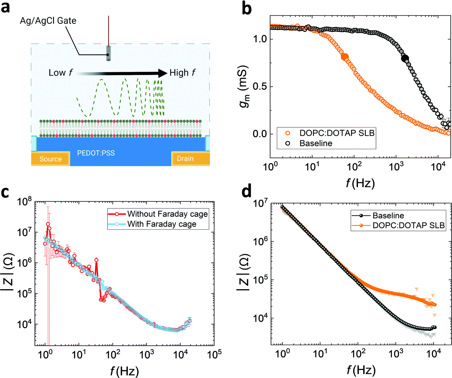 | ||
| Fig. 3 (a) Schematic of DOPC:DOTAP SLB formed on OECT channel and analysed by frequency dependent measurements. (b) Bandwidth measurement before and after SLB formation (cut-off frequency is labelled with larger solid circles). (c) The reduction of low frequency noise and propagation error of Ig-based OECT impedance measurements with a Faraday cage. (d) The impedance spectra stitched by the high frequency of Ig-based (electrode) spectra and low frequency of Id-based (OECT) spectra (the shaded triangles and circles are Id-based and Ig-based measurements, respectively. In this case, the visible shading data points demonstrate larger propagated error in Z). | ||
Generally, OECTs with smaller PEDOT:PSS-channel areas greatly reduce the sampling area, which increases the possibility of sensing high-quality lipid barrier among a non-uniform SLB. Rivnay et al. previously reported a method to overcome noise and measurement errors during EIS measurements for measuring cell-based tissue barrier impedance. Here, we adapted the method using OECTs, stitching together data from operation of the devices both as electrodes and transistors, to reduce noise and maintain good SNR at both high and low frequencies.23 For the OECT frequency-dependent measurement, a sinusoidal voltage with variation of frequency and 10 mV amplitude is added to the gate (Vg), whereas a drain bias, Vd = −0.6 V, is applied to the channel, measured by modulating the channel current (Id) with low gate currents (Ig) over a range of frequencies (1–104 Hz).33 Since Id is induced and modulated by the number of ions injected into the channel, transconductance (gm = ΔId/ΔVg), as a key characteristic, depicts the ionic transport efficiency to the channel at the steady state of the transistor.33 When the SLB is formed on the channel, it acts as a barrier to ion-injection, so the gating efficiency of the OECT is dramatically reduced (Fig. 3b). In this gmvs. frequency plot, the cut-off frequency (fcut-off), is reduced from 1.6 kHz to 60 Hz once the SLB is formed on the channel indicating a strong barrier to ion penetration.
High transconductance PEDOT:PSS OECTs can provide very high accuracy data at low frequency. As described by Rivnay et al.,23 the drain current-deduced transconductance (gm) can be converted to impedance. However, the shortcoming of Id-based impedance is the loss of data accuracy at high frequency, due to the slow operation of the device. The Ig-based impedance, Z = ΔVg/ΔIg, is intrinsically the same as the EIS measurement of an electrode with a potentiostat.23 We show that the Ig-derived OECT impedance spectra from the gate current, can be compared with EIS derived from the channel of the OECT used as an electrode measured with a potentiostat (Fig. S7b, ESI†). Although Id and Ig spectra may not be inherently noisy when measuring baselines (Fig. S8a, ESI†), the addition of the biological component, the SLB, integrates a high degree of noise (Fig. S8b, ESI†).23 Noise can be mitigated through the use of a Faraday cage. Indeed, this is illustrated (Fig. 3c) for the case of the Ig-based spectra, which has a higher propagation error and noise at low frequencies, although is highly accurate at high frequencies. However, the use of the Faraday cage can be avoided, and accurate impedance spectra to represent the SLB properties is generated through stitching the low frequency of Id-based data and high frequency of Ig-based data, from a single device, as a strategy (Fig. 3d) to gain more reliable and accurate information about SLB characteristics. As mentioned above, Herein, we arbitrarily set the value of 60 Hz as the boundary between low and high frequency for the convenience of discussion and demonstration. This also obviates the need to capture EIS data from a potentiostat. The resulting spectrum has low propagation error from 1 to 104 Hz. This strategy provides high confidence in the impedance spectra and overcomes the inaccuracy at low frequency from traditional EIS measurements, which can be crucial for detecting SLB impedance across a broader range of frequencies.
Conclusions
Here, we have systematically demonstrated how key factors such as composition of SLB, size of PEDOT:PSS electrode, and types of devices (microelectrode vs. OECT) may impact characteristic features of measurement sensitivity and data quality of frequency-dependent impedance spectroscopy of cell membrane mimics. The SLBs with native cell components generally exhibit lower Rm compared to the all-lipid SLBs due to decreased sealing caused by the defects arising from the native components on the bilayer. The differences in the measured resistance between native and all-lipid SLBs dominate the signals observed. A real-time toxicity study of α-HL is performed on the all-lipid SLB to demonstrate the capability of a toxin dose–response study on SLBs. Using simulations, we interpret the insertion dominating process (left shift of the capacitance slope) at low dose and pore-formation dominating process (plateau in the resistance decrease) at high doses of α-HL.By simulating various electrode sizes, a larger area of PEDOT:PSS is found to be more sensitive to both bilayer resistance and capacitance. However, a larger device size increases the possibility of defects in the SLB, so larger devices demand high membrane quality. To take advantage of the low-possibility of defects on a smaller area of PEDOT:PSS, we further investigated OECTs with smaller PEDOT:PSS channels, as impedance sensors of SLBs by performing two modes of impedance measurements, and stitching the two spectra together. Impedance from both Ig-based and Id-based measurement can produce high-quality impedance data describing SLB features with low noise and propagation errors. Combined, our studies reveal the key characteristics of SLBs and properties of devices for developing more sensitive membrane-on-chip systems, to progress towards a more reliable platform for cell membrane research.
Future work will concentrate on more accurate extraction of membrane capacitance from the EIS measurement. This difficulty is caused by the abnormal impedance behaviour beyond the high frequency (105 Hz). Also, the lower membrane resistance of SLB on PEDOT:PSS is still a shortcoming compared to membrane resistance from live cells, so the interface chemistry between PEDOT:PSS and lipid bilayer for high quality membrane formation can be a focus for further investigation.
Experimental
Device fabrication
The fabricated devices were PEDOT:PSS microelectrodes and OECTs. The microelectrodes used in Fig. 1 were circular electrodes with 450 μm diameters and the OECTs used in Fig. 3 have 50 μm by 50 μm channels. To fabricate the devices, 4 inch glass wafers first were cleaned by sonication in acetone and then isopropanol for 15 minutes. The wafers were rinsed with DI water and baked 15 minutes at 150 °C. To pattern for contact tracks, a negative photoresist, AZ nLOF2035 (Microchemicals GmbH) was spun on the glass wafer with 3000 rpm for 45 seconds and exposed with UV light using mask aligner (Karl Suss MA/BA6). The photoresist was developed in AZ 726 MIF developer (MIcroChemicals) developer for 28 seconds. Ti (5 nm)/Au (100 nm) layer as conductive tracks was deposited by e-beam evaporation on top of wafer and the Ti–Au metal layer was lifted-off by soaking in NI555 (Microchemicals GmbH) overnight. Prior to the deposition of 2 μm layer (sacrificial layer) of parylene C ((SCS), the wafer was soaked with 3% A174 (3-(trimethoxysilyl)propyl methacrylate) in ethanol solution (0.1% acetic acid in ethanol) 60 seconds to promote the parylene C adhesion on the wafer. An anti-adhesive layer of Micro-90 in DI water (2% v/v solution) was spun (1000 rpm for 45 seconds), and then the second layer of 2 μm parylene C (SCS) was deposited. A layer of positive photoresist AZ 10XT (Microchemicals GmbH) was spun with 3000 rpm for 45 seconds and developed in AZ 726 MIF developer (MIcroChemicals) for 6 minutes to pattern electrode areas or OECT channels. Reactive ion etching (Oxford 80 Plasmalab plus) opened the window for deposition of Clevios PH500 PEDOT:PSS (Heraeus). The PEDOT:PSS solution containing 5 vol% ethylene glycol, 0.26 vol% dodecylbenzenesulfonic acid (DBSA), and 1 vol% (3-glycidyloxypropyl)trimethyloxy-silane (GOPS) was spin-coated at 3000 rpm for 45 seconds. The sample was baked at 90 °C for 1 minute, and the sacrificial layer was peeled off. Finally, the sample was put on a hot plate at 130 °C for 1 hour before use.Preparation of liposomes
Twenty-five mg mL−1 of 1,2-dioleoyl-sn-glycero-3-phosphocholine (DOPC) and 1,2-dioleoyl-3-trimethylammonium-propane (DOTAP), (Avanti Polar Lipids) in chloroform were mixed in the desired 4:1 ratio and dried under nitrogen gas. The lipid mix was dried under vacuum in room temperature for one hour, to evaporate the residual chloroform. The lipids were then resuspended in PBS to a concentration of 4 mg mL−1. The solution was freezed at −20 °C for at least 5 hours, and then extruded 20 times through a 100 nm membrane (GE Healthcare).
Formation of supported lipid bilayers (SLBs)
100 μL of liposomes (DOPC:DOTAP 4 mg mL−1 in PBS) were added on PEDOT:PSS based electrodes/OECTs after 1 minute of air plasma (Harrick Plasma, Ithaca, NY) at 18 W. The liposomes were incubated for 20 minutes and then rinsed with PBS (3 times). A poly(ethylene glycol) solution in PBS (PEG8k, 30% w/v) was then added to the well and incubated for another 20 minutes. Lastly, the SLBs were washed with PBS 5 times before measurements.Formation of native supported lipid bilayers (SLBs)
100 μL of blebs were added to PEDOT:PSS based electrode/OECT after 1 minute of air plasma (Harrick Plasma, Ithaca, NY) at 18 W. The blebs were incubated for 20 minutes and then rinsed with PBS 3 times. All-lipid liposomes (DOPC:DOTAP 4 mg mL−1 in PBS) were added and incubated for 20 minutes and then rinsed with PBS (3 times). A poly(ethylene glycol) solution in PBS (PEG8k, 30% w/v) was then added to the well and incubated for another 20 minutes. Lastly, the SLBs were washed with PBS 5 times before measurements.Fluorescence recovery after photobleaching measurements (FRAP)
FRAP experiments were performed on an inverted Zeiss LSM800 confocal microscope (Zeiss Germany) with a 10× objective. To label the membrane, 1 μL of 0.36 mM octadecyl rhodamine B chloride (R18, Molecular Probes) fluorophore was added to 200 μL of bleb or liposome solution in a soft sonication bath for 15 minutes. Excess fluorophore was removed by using a G25 spin column (GE Healthcare). Starting from the labelled blebs, supported lipid bilayers were assembled as described previously. A 150 mW 561 nm optically pumped semiconductor laser (Coherent, Inc.) was used to photobleach a 30 μm diameter spot in the supported lipid bilayer and its fluorescence intensity recovery was monitored up to 20 minutes. The fluorescence intensity change over time was fitted using a Bessel function, following the method of Soumpasis.34 The diffusion coefficient was calculated with the following equation:| D = w2/4t1/2 | (1) |
Electrochemical impedance spectroscopy with potentiostat
An Autolab PGSTAT128N potentiostat equipped with a frequency response analyser was used to record impedance spectra in the frequency range between 0.1 Hz–100 kHz. Commercial Ag/AgCl and a platinum mesh were used as reference and counter electrodes, respectively. The micro-fabricated PEDOT:PSS coated Au electrodes or PEDOT:PSS channel of OECTs (shorting source and drain) were used as the working electrodes. An AC voltage of 0.01 V and a DC voltage of 0 V versus OCP (open circuit potential) were applied. All measurements were taken in around 200 μL PBS retained on the chip by a glass well.Alpha-hemolysin test on DOPC:DOTAP SLB
EIS was measured after formation of DOPC:DOTAP (SLB). Then, SLBs were incubated at 37 °C for 30 minutes for lipid stabilization and EIS was measured to obtain the baseline before the toxin test. Different concentrations of α-HL were prepared in PBS. During the experiment, 100 μL of α-HL solution was added into 100 μL PBS from lowest to the highest concentration into the well, so the final concentrations of α-HL represented at two-fold of the original concentration. The SLB was incubated with each α-HL concentration at 37 °C for 10 minutes, and then EIS was measured right after each incubation.Transistor impedance, EIS with potentiostat, and optical measurements on the same channel
OECTs were characterised under a confocal microscope using a dual-channel source-meter unit (NI-PXI) with custom-written control code in LabVIEW. All measurements were performed using an Ag/AgCl pellet (D = 2 mm × H = 2 mm – Warner instruments) as the gate electrode. The PEDOT:PSS channels were 50 μm in length and 50 μm in width with total 80% overlapping with gold (source and drain). After the SLB stained with R18 and formed on the channel. FRAP measurements were performed with a 10× magnification objective before electronic monitoring. A drain voltage −0.6 V and an alternating gate voltage with 0.01 V amplitude were continuously applied. The gate voltage frequency covered 1–10 kHz. The same device with the same SLB was also monitored with EIS with potentiostat by shorting the source and drain electrodes and measurement procedure was mentioned previously.Noise optimisation with/without Faraday cage
The OECT bandwidth and impedance measurement were measured in two conditions: one condition was to measure pristine OECT with hanging Ag/AgCl gate on the top of a lab bench without Faraday cage. The other condition was to measure the same setup within a Faraday cage.Simulation
The parameter values for the simulation were obtained by applying a least-squares regression to the HEK 293 SLB data shown in Fig. 1b. The values were rounded, to give: Re = 200 Ω, Cp = 2 μF, Cm = 7 nF, Rm = 7 kΩ. These constitute the set of fitted parameter values. The change in impedance as a function of each parameter was determined by calculating the equivalent circuit impedance over the frequency range of interest {10−1–107} Hz for different parameter values, over the range {0.1–4} × (fitted parameter value), apart from the simulation in Fig. 2a which was simulated over the range Cp = {0.01–2} × Cp,fitted. The simulations in Fig. 2a, as well as those of the system sensitivity (Fig. 2c and d), were conducted under the assumptions: Cp and Cm are linearly proportional to the cross-sectional surface area of the PEDOT:PSS electrode (i.e. PEDOT:PSS film has constant height), Re and Rm are inversely proportional to the square root of the cross-sectional surface area of the PEDOT:PSS electrode, and therefore Cp and Re (Rm) are related by Re ∝ CP−1/2 (Rm ∝ CP−1/2). Thus, the value for Re was substituted into the calculation as 283 mΩ F/Cp. Similarly, Rm was substituted as 9.8995 ΩF/Cp and Cm was substituted as 3.5 × 10⁻³/Cp. The sensitivity surfaces were determined by calculating the admittance over the frequency range of interest. The sensitivity of the system to a particular parameter value was determined by calculating admittance for different parameter values of interest, over the range {10−3–10} × (fitted parameter value of interest). The l1-norm of the difference between the admittance at the edge cases 10−3 × (fitted parameter value) and 10 × (fitted parameter value) was taken as a proxy for sensitivity. This was repeated for the PEDOT:PSS capacitance values, Cp = {10−6–100} × (Cm,fittedvalue), as well as for different Cm and Rm values, over the range {10−5–105} × (Cm,fittedvalue or Rm,fittedvalue).
HEK293 cell culture
Human embryonic kidney 293 cells (HEK-293; kind gift from Marc Borsotto, Université de Nice Sophia Antipolis, France) were cultured in 75 cm2 flasks with advanced Dulbecco's modified Eagle medium (DMEM; Thermo Fisher Scientific, TFS) with the addition of 10% foetal bovine serum (Merck), 50 U mL−1 penicillin and 50 μg mL−1 streptomycin (TFS), 1% (v/v) GlutaMax (TFS), and 50 μg mL−1 gentamicin (TFS). Cells were cultured in incubator (at 37 °C, with 5% CO2, and in humidity) until 80–90% confluent before passaging, and cells were cultured until P60.Preparation of plasma cell membrane vesicles (Blebs)
HEK cells were seeded in culture dishes (10 cm, Corning) and grown for 24–48 hours at 37 °C, 5% CO2 incubator. Cells were then washed with GPMV buffer (2 mM CaCl2, 10 mM HEPES, 150 mM NaCl at pH 7.4) and then incubated with 4 mL of GPMV buffer supplemented with 25 mM formaldehyde (FA) and 2 mM dithiothreitol (DTT) to induce formation of blebs, for 1.5 hours at 37 °C. The solution containing the blebs was placed on ice for 15 minutes to separate cell debris from blebs, which were subsequently collected from the supernatant.Author contributions
ZL conceptualized the comparison method of the native membrane and all-lipid membrane with EIS approach and the strategy of stitching characteristic OECT impedances for SLB sensing. AS, AMP, DVN, ZL, and QT conceptualized the simulation aspect of the research. ZL microfabricated the microelectrodes and OECTs and conducted the experiment of native and all-lipid SLB formation, EIS, FRAP measurements, and α-HL disruption tests. DVN performed the simulation of the EIS data. AS performed the EIS measurements of SLB formation with size-effect of microelectrode. The first draft was written by ZL and DVN, and edited by KK, AMP, AS, RMO and Salleo, A. The project was supervised throughout by RMO and AMP.Conflicts of interest
The authors declare no conflict of interest.Acknowledgements
R. O., and A. S. acknowledge funding for this project, sponsored by the Defense Advanced Research Projects Agency (DARPA) Army Research Office and accomplished under Cooperative Agreement Number W911NF-18-2-0152. The views and conclusions contained in this document are those of the authors and should not be interpreted as representing the official policies, either expressed or implied, of DARPA or the Army Research Office or the U.S. Government. The U.S. Government is authorized to reproduce and distribute reprints for Government purposes notwithstanding any copyright notation herein. The schematic illustrations on Fig. 1–3 were created using Biorender.com. Finally, ZL acknowledges Dr Sanggil Han and Dr Anastasios G. Polyravas for training in the microfabrication of the devices.Notes and references
- J. P. Overington, B. Al-Lazikani and A. L. Hopkins, Nat. Rev. Drug Discovery, 2006, 5, 993–996 CrossRef CAS PubMed.
- L. K. Tamm and H. M. McConnell, Biophys. J., 1985, 47, 105–113 CrossRef CAS PubMed.
- Y. Zhang, S. Inal, C. Y. Hsia, M. Ferro, M. Ferro, S. Daniel and R. M. Owens, Adv. Funct. Mater., 2016, 26, 7304–7313 CrossRef CAS.
- J. M. Crane and L. K. Tamm, Methods Mol. Biol., 2007, 400, 481–488 CrossRef CAS PubMed.
- Y. F. Dufrêne and G. U. Lee, Biochim. Biophys. Acta, Biomembr., 2000, 1509, 14–41 CrossRef.
- K. L. Weirich, J. N. Israelachvili and D. K. Fygenson, Biophys. J., 2010, 98, 85–92 CrossRef CAS PubMed.
- R. P. Richter and A. R. Brisson, Biophys. J., 2005, 88, 3422–3433 CrossRef CAS PubMed.
- R. Goers, J. Thoma, N. Ritzmann, A. Di Silvestro, C. Alter, G. Gunkel-Grabole, D. Fotiadis, D. J. Müller and W. Meier, Commun. Chem., 2018, 1, 1–10 CrossRef CAS.
- E. Sezgin, H. J. Kaiser, T. Baumgart, P. Schwille, K. Simons and I. Levental, Nat. Protoc., 2012, 7, 1042–1051 CrossRef CAS PubMed.
- H.-Y. Liu, H. Grant, H.-L. Hsu, R. Sorkin, F. Bošković, G. Wuite and S. Daniel, ACS Appl. Mater. Interfaces, 2017, 9, 35526–35538 CrossRef CAS PubMed.
- M. J. Richards, C.-Y. Hsia, R. R. Singh, H. Haider, J. Kumpf, T. Kawate and S. Daniel, Langmuir, 2016, 32, 2963–2974 CrossRef CAS PubMed.
- J. Rivnay, S. Inal, A. Salleo, R. M. Owens, M. Berggren and G. G. Malliaras, Nat. Rev. Mater., 2018, 3, 17086 CrossRef CAS.
- F. Torricelli, D. Z. Adrahtas, Z. Bao, M. Berggren, F. Biscarini, A. Bonfiglio, C. A. Bortolotti, C. D. Frisbie, E. Macchia, G. G. Malliaras, I. McCulloch, M. Moser, T.-Q. Nguyen, R. M. Owens, A. Salleo, A. Spanu and L. Torsi, Nat. Rev. Methods Primers, 2021, 1, 1–24 CrossRef.
- M. Sessolo, D. Khodagholy, J. Rivnay, F. Maddalena, M. Gleyzes, E. Steidl, B. Buisson and G. G. Malliaras, Adv. Mater., 2013, 25, 2135–2139 CrossRef CAS PubMed.
- D. A. Koutsouras, L. V. Lingstedt, K. Lieberth, J. Reinholz, V. Mailänder, P. W.-M. Blom and P. Gkoupidenis, Adv. Healthcare Mater., 2019, 8, 1901215 CrossRef CAS PubMed.
- A.-M. Pappa, H.-Y. Liu, W. Traberg-Christensen, Q. Thiburce, A. Savva, A. Pavia, A. Salleo, S. Daniel and R. M. Owens, ACS Nano, 2020, 14, 12538–12545 CrossRef CAS PubMed.
- H. Y. Liu, A. M. Pappa, A. Pavia, C. Pitsalidis, Q. Thiburce, A. Salleo, R. M. Owens and S. Daniel, Langmuir, 2020, 36, 7325–7331 CrossRef CAS PubMed.
- W. Hoiles, V. Krishnamurthy and B. Cornell, IEEE Trans. Biomed. Circuits Syst., 2015, 9, 321–333 Search PubMed.
- G. Valincius, T. Meškauskas and F. Ivanauskas, Langmuir, 2012, 28, 977–990 CrossRef CAS PubMed.
- G. Valincius and M. Mickevicius, Adv. Planar Lipid Bilayers Liposomes, 2015, 21, 27–61 Search PubMed.
- J. Nissa, P. Janson, M. Berggren and D. T. Simon, Adv. Electron. Mater., 2021, 7, 2001173 CrossRef CAS.
- G. C. Faria, D. T. Duong, A. Salleo, C. A. Polyzoidis, S. Logothetidis, J. Rivnay, R. Owens and G. G. Malliaras, MRS Commun., 2014, 4, 189–194 CrossRef CAS.
- J. Rivnay, M. Ramuz, P. Leleux, A. Hama, M. Huerta and R. M. Owens, Appl. Phys. Lett., 2015, 106, 043301 CrossRef.
- P. Jurkiewicz, A. Olzyńska, M. Langner and M. Hof, Langmuir, 2006, 22, 8741–8749 CrossRef CAS PubMed.
- D. Loveday, P. Peterson and B. Rodgers, CoatingsTech, 2004, 1, 46–52 CAS.
- L. Song, M. R. Hobaugh, C. Shustak, S. Cheley, H. Bayley and J. E. Gouaux, Science, 1996, 274, 1859–1866 CrossRef CAS PubMed.
- B. J. Berube and J. B. Wardenburg, Toxins, 2013, 5, 1140–1166 CrossRef PubMed.
- N. K. Sarangi, A. Stalcup and T. E. Keyes, ChemElectroChem, 2020, 7, 4535–4542 CrossRef CAS.
- M. Bianchi, S. Carli, M. Di Lauro, M. Prato, M. Murgia, L. Fadiga and F. Biscarini, J. Mater. Chem. C, 2020, 8, 11252–11262 RSC.
- J. T. Friedlein, R. R. McLeod and J. Rivnay, Org. Electron., 2018, 63, 398–414 CrossRef CAS.
- D. A. Koutsouras, P. Gkoupidenis, C. Stolz, V. Subramanian, G. G. Malliaras and D. C. Martin, ChemElectroChem, 2017, 4, 2321–2327 CrossRef.
- S. Daniel, F. Albertorio and P. S. Cremer, MRS Bull., 2006, 31, 536–540 CrossRef CAS.
- D. Khodagholy, J. Rivnay, M. Sessolo, M. Gurfinkel, P. Leleux, L. H. Jimison, E. Stavrinidou, T. Herve, S. Sanaur, R. M. Owens and G. G. Malliaras, Nat. Commun., 2013, 4, 1–6 Search PubMed.
- D. M. Soumpasis, Biophys. J., 1983, 41, 95 CrossRef CAS PubMed.
Footnote |
| † Electronic supplementary information (ESI) available. See DOI: https://doi.org/10.1039/d2tc00826b |
| This journal is © The Royal Society of Chemistry 2022 |