 Open Access Article
Creative Commons Attribution 3.0 Unported Licence
Experimental and computational investigation on the formation pathway of [RuCl2(CO)2(ERR′)2] (E = S, Se, Te; R, R′ = Me, Ph) from [RuCl2(CO)3]2 and ERR′ †
Marjaana
Taimisto
 a,
Tom
Bajorek‡
a,
J. Mikko
Rautiainen
a,
Tom
Bajorek‡
a,
J. Mikko
Rautiainen
 b,
Tapani A.
Pakkanen
 a,
Raija
Oilunkaniemi
 *a and
Risto S.
Laitinen
 *a
*a
aLaboratory of Inorganic Chemistry, Environmental and Chemical Engineering, University of Oulu, P.O. Box 3000, 90014 Oulu, Finland. E-mail: risto.laitinen@oulu.fi
bDepartment of Chemistry and Nanoscience Center, University of Jyväskylä, P.O. Box 35, 40014 Jyväskylä, Finland
First published on 12th July 2022
Abstract
The pathways to the formation of the series of [RuCl2(CO)2(ERR′)2] (E = S, Se, Te; R, R′ = Me, Ph) complexes from [RuCl2(CO)3]2 and ERR′ have been explored experimentally in THF and CH2Cl2, and computationally by PBE0-D3/def2-TZVP calculations. The end-products and some reaction intermediates have been isolated and identified by NMR spectroscopy, and their crystal structures have been determined by X-ray diffraction. The relative stabilities of the [RuCl2(CO)2(ERR′)2] isomers follow the order cct > ccc > tcc > ttt ≈ ctc (the terms c/t refer to cis/trans arrangement of the ligands in the order of Cl, CO, and ERR′). The yields were rather similar in both solvents, but the reactions were significantly faster in THF than in CH2Cl2. The highest yields were observed for the telluroether complexes, and the yields decreased with lighter chalcogenoethers. PBE0-D3/def2-TZVP calculations indicated that the reaction path is independent of the nature of the solvent. The substitution of one CO ligand of the intermediate [RuCl2(CO)3(ERR′)] by the second ERR′ shows the highest activation barrier and is the rate-determining step in all reactions. The observed faster reaction rate in THF than in CH2Cl2 upon reflux can therefore be explained by the higher boiling point of THF. At room temperature the reactions in both solvents proceed equally slowly. When the reaction is carried out in THF, the formation of [RuCl2(CO)3(THF)] is also observed, and the reaction may proceed with the substitution of THF by ERR′. The formation of the THF complex, however, is not necessary for the dissociation of the [RuCl2(CO)3]2. Thermal energy at room temperature is sufficient to cleave one of the bridging Ru–Cl bonds. The intermediate thus formed undergoes a facile reaction with ERR′. This mechanism is viable also in non-coordinating CH2Cl2.
Introduction
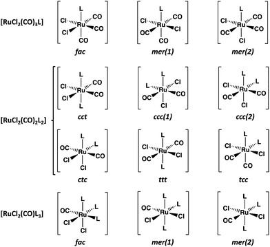
Carbon monoxide releasing molecules (CORMs) have turned out to be important in safe applications of CO in therapeutics. Suitable molecules include organometallic complexes, aldehydes, cyclic diketones, and carboxylic acids, among others (for some selected examples of recent reviews, see ref. 1). While [RuCl2(CO)3]2 (CORM-2) is a useful carbon monoxide releasing compound, it is also a convenient reagent in the preparation of mononuclear complexes of ruthenium (for the syntheses and structural characterization of selected complexes with different non-metallic donor atoms during the past ten years, see ref. 2). The main products in these reactions with monodentate ligands are [RuCl2(CO)3L]2a,c,e,g,h and [RuCl2(CO)2L2]2a–c,g,l (see Chart 1).The fac-isomer is most common for [RuCl2(CO)3L], as exemplified by the recent X-ray structural determinations,2c,g,h and also indicated by NMR spectroscopy.2a,c,e,g,h In case of [RuCl2(CO)2L2], the cct isomers are predominant,2a,b,g,l though the tcc-isomer has also been reported.2c In case of polydentate chelating ligands, the actual isomer depends on the stereochemical requirements by the ligand.2d,f,i,j
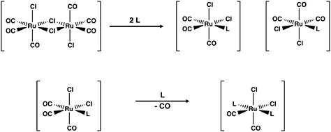
The formation of [RuCl2(CO)3L] and [RuCl2(CO)2L2] is generally thought to be sequential with the initial interaction between the incoming ligand and the ruthenium centre leading to the symmetric cleavage of the bridging chlorido ligands3 (see Scheme 1). The second part of the reaction is the substitution of CO by the incoming ligand in the mononuclear complexes thus formed.
The coordination of a solvent molecule Solv to [RuCl2(CO)3]2 has been suggested to be an initial step in the reaction resulting in the formation of mononuclear fac-[RuCl2(CO)3(Solv)]. The ligand substitution of Solv by the incoming ligand L leads to fac-[RuCl2(CO)3L]. The substitution of CO by the second ligand affords the final product (see Scheme 1). This is exemplified by the reactions of [RuCl2(CO)3]2 with bipyridine ligands in different solvents.3 While this approach is logical and is generally accepted, there is no direct experimental or computational evidence that the ligand substitution in [RuCl2(CO)3]2 really follows this pathway. The current contribution addresses this issue by exploring the reaction of [RuCl2(CO)3]2 with chalcogenoethers ERR′ (E = S, Se, Te; R, R′ = Me, Ph).
Mononuclear chalcogenoether complexes of ruthenium have long been known (for early literature, see reviews in ref. 4). During the last three decades these complexes have attracted more attention, which is centered on the ligand chemistry of seleno- and telluroethers in addition to thioethers (for more recent reviews, see ref. 5). Hieber and John6 explored already in 1970s the isomerism of [RuCl2(CO)2(ERR′)2] (E = S, Se, Te; R, R′ = a number of alkyl or aryl groups) by recording the dipole moments, IR spectra, and 1H NMR spectra of the complexes formed in different reactions. John6b inferred that the main isomer in each complex is the cct (see Chart 1). The later crystal structure determinations of [RuCl2(CO)2(SPh2)2],7 [RuCl2(CO)2(TePh2)2],8 and [RuCl2(CO)2{Te(CH2SiMe3)2}2]9 have confirmed that in the solid state, all three complexes indeed exist as cct-isomers.
As part of our pursuit to explore the formation mechanism of [RuCl2(CO)2L2] complexes we have investigated in this contribution the formation, stereochemistry, and isomerism of [RuCl2(CO)2(ERR′)2] (E = S, Se, Te; R, R′ = Me, Ph) complexes (see Table 1). We report the crystal structures of 2cct, 4cct, and 6cct, as well as the isolation and characterization of [RuCl2(CO)3(SeMe2)] (10) and [RuCl2(CO)3(SeMePh)] (11) complexes that are potential intermediate products along the reaction path. The reaction pathway has been explored by PBE0-D3/def2-TZVP calculations.
| [RuCl2(CO)2(SMe2)2] 1cct, 1ccc, 1tcc, 1ttt, 1ctc | [RuCl2(CO)2(SMePh)2] 2cct, 2ccc, 2tcc, 2ttt, 2ctc | [RuCl2(CO)2(SPh2)2] 3cct, 3ccc, 3tcc, 3ttt, 3ctc |
| [RuCl2(CO)2(SeMe2)2] 4cct, 4ccc, 4tcc, 4ttt, 4ctc | [RuCl2(CO)2(SeMePh)2] 5cct, 5ccc, 5tcc, 5ttt, 5ctc | [RuCl2(CO)2(SePh2)2] 6cct, 6ccc, 6tcc, 6ttt, 6ctc |
| [RuCl2(CO)2(TeMe2)2] 7cct, 7ccc, 7tcc, 7ttt, 7ctc | [RuCl2(CO)2(TeMePh)2] 8cct, 8ccc, 8tcc, 8ttt, 8ctc | [RuCl2(CO)2(TePh2)2] 9cct, 9ccc, 9tcc, 9ttt, 9ctc |
Experimental
General
The syntheses of SeMePh and TeMePh were carried out under an inert atmosphere by using Schlenk techniques. The reactions with [RuCl2(CO)3]2 were carried out in air. [RuCl2(CO)3]2 (Johnson Matthey), Te2Ph2 (Aldrich), Se2Ph2 (Aldrich), SMePh (Fluka Chemicals), methyl iodide (Baker), SeMe2 (Fluka Chemicals), NaBH4 (Merck), and n-hexane (Kebolab) were used as purchased. Tetrahydrofuran (Lab-Scan) and diethyl ether (Lab-Scan) were dried over Na/benzophenone and dichloromethane (Lab-Scan) over P4O10. Methanol (Fisher Sci. Int. Co) was deoxygenated with argon prior to use.NMR spectroscopy
The 13C{1H}, 77Se, and 125Te NMR spectra were recorded at room temperature on a Bruker DPX 400 spectrometer operating at 100.61, 76.31, and 126.24 MHz, respectively. The respective spectral widths were 25.06–26.04, 30.18–53.33, and 37.88–63.49 kHz. The pulse width was 4.0 μs for 13C, 6.7 μs for 77Se, and 10.0 μs for 125Te. The 13C{1H} NMR spectra were referenced to the solvent resonance and are reported relative to Me4Si. Saturated solutions of SeO2 (aq) and H6TeO6 (aq) were used as external standards for 77Se and 125Te chemical shifts. Chemical shifts (ppm) are reported relative to neat SeMe2 and TeMe2 [δ(SeMe2) = δ(SeO2) + 1302.6 (ref. 10) and δ(TeMe2) = δ(H6TeO6) + 710.9 (ref. 11)].X-ray diffraction
Diffraction data of 2cct, 4cct, 6cct, 10, and 11 were collected on a Bruker Nonius Kappa-CCD diffractometer using graphite monochromated MoKα radiation (λ = 0.71073 Å; 55 kV, 25 mA). Crystal data and the details of the structure determinations are given in Table S1 in ESI.†Structures were solved by direct methods using SHELXS-2016 and refined using SHELXL-2016.12 After the full-matrix least-squares refinement of the non-hydrogen atoms with anisotropic thermal parameters, the hydrogen atoms were placed in calculated positions in the aromatic rings (C–H = 0.95 Å) and in the CH3 groups (C–H = 0.98 Å). The scattering factors for the neutral atoms were those incorporated with the programs.
Quality of the obtained crystals of 8cct enabled only an approximate refinement of the structure. The refinement required constraining the thermal parameters of all carbon atoms to be equal. This complex and the approximate metrical data of bond parameters are shown in ESI (Fig. S1†), since the accuracy of the crystal structure determination was sufficient for the identification of the species and therefore allowed the unambiguous assignment of the 125Te NMR resonance.
Preparation of SeMePh and TeMePh
Diphenyl diselenide or ditelluride (0.507 g, 1.64 mmol and 0.658 g, 1.61 mmol, respectively) was dissolved in 25 mL of THF, and a solution of NaBH4 in MeOH was added dropwise at 0 °C until the solution turned colourless. Methyl iodide (0.200 mL, 3.20 mmol) was added, and the solution was stirred at room temperature for two hours. The reaction mixture was poured into water and extracted with diethyl ether in several portions. The combined organic layers were dried on MgSO4. Evaporation of the solvent afforded SeMePh as a light-yellow oil (0.454 g, yield 83%) and TeMePh as a yellow oil (0.471 g, yield 67%). SeMePh: NMR (δ, ppm) (CDCl3): 13C{1H} 6.7 (s, CH3), 125.8, 128.9, 129.9, 131.9; 77Se 197 (cf. lit. 197 (ref. 13)). TeMePh: NMR (δ, ppm) (CDCl3): 13C{1H} −17.2 (s, CH3), 112.3, 126.9, 129.0, 136.3; 125Te 328 (cf. lit. 329 (ref. 14)).General procedure for the preparation of [RuCl2(CO)2(ERR′)2] (E = S, Se, Te; R, R′ = Me, Ph)
A typical synthesis was carried out by dissolving ERR′ (E = S, Se, Te; R, R′ = Me, Ph) in 5 mL of CH2Cl2 or THF and adding the resulting solution dropwise to a suspension of [RuCl2(CO)3]2 in 15 mL of the same solvent. The mixture was refluxed until a clear solution was obtained (typical times were 50–100 h in CH2Cl2 and 5–10 h in THF). The solution was evaporated to half of the original volume and hexane was added. The precipitate was separated by filtration and re-crystallized from CH2Cl2/hexane at +3 °C. In some reactions, two crops of crystals were formed. They were manually separated under the microscope. The quantitative information of the syntheses, as well as the assignment of the NMR spectra and the identification of the complexes are given in sections 1 and 4 in ESI.†Computational details
All structures were optimized using Gaussian 16 program package,15 PBE0 DFT functional,16 and def2-TZVP17 basis sets. Implicit C-PCM solvent model was applied to treat the solvation effects,18 and Grimme's empirical correction with Becke–Johnson damping to model the dispersion forces.19 All calculated minimum structures were stationary points on the potential surface free of imaginary frequencies and all transition state structures have one imaginary frequency corresponding to the reaction coordinate they are describing. The optimized Cartesian coordinates of the atoms in all computed species are given in section 5.4 in ESI.†Results and discussion
Formation of [RuCl2(CO)2(ERR′)2] (E = S, Se, Te; R, R′ = Me, Ph)
In organic solvents, [RuCl2(CO)3]2 reacts with organic monochalcogenides to form [RuCl2(CO)2(ERR′)2] (eqn (1)). | (1) |
The syntheses were carried out by refluxing in CH2Cl2 or THF. Though the products and their yields were rather similar in both solvents, the reaction seemed to be faster in THF than in CH2Cl2. There was a clear trend observed for the yields of the complexes, as the chalcogen element became heavier. In case of [RuCl2(CO)2(SRR′)2] the yields were 10–30%, [RuCl2(CO)2(SeRR′)2] showed yields of 30–40%, and [RuCl2(CO)2(TeRR′)2] were formed at good yields of ca. 80%.
Molecular structures
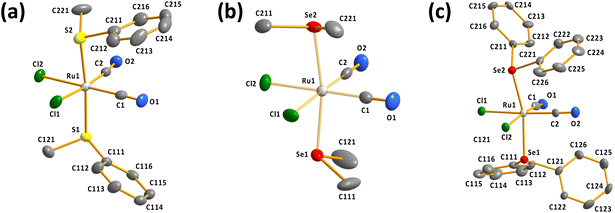
It can be seen from Fig. 1 that all determined complexes are expectedly octahedral cct-isomers in line with the previously reported structures.7–9 The selected bond parameters of the different cct-[RuCl2(CO)2(ERR′)2] complexes are compared in Table S2 in ESI.†
The Ru–S, Ru–Se, and Ru–Te bond lengths span ranges of 2.3774(12)–2.4084(11), 2.4908(7)–2.5125(7), and 2.6478(7)–2.6637(7) Å, respectively. The Ru–S and Ru–Se bonds appear to be slightly longer than the respective sums of covalent radii of 2.28 and 2.41 Å,20 but the Ru–Te bond lengths are near to the single bonds (the sum of the covalent radii is 2.61 Å (ref. 20)). Interestingly, the two Ru–E (E = S, Se, Te) bonds in each complex are bent away from the region of two Ru–CO bonds [the E–Ru–E bond angles range 164.01(3)–174.11(4)°; see Table S2 in ESI†].
Geometries of all [RuCl2(CO)2(ERR′)2] isomers were optimized using the PBE0-D3/def2-TZVP method and the optimized structures are summarized in Table S5 in ESI.† The relative energies of the isomers differ significantly, as shown in Fig. 2. The stability ordering is cct > ccc > tcc > ttt ≈ ctc.
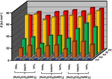 | ||
| Fig. 2 Relative PBE0/def2-TZVP Gibbs energies (in kJ mol−1) of [RuCl2(CO)2(ERR′)2] (E = S, Se, Te; R, R′ = Me, Ph). The numerical values of the relative energies are shown in Table S6 in ESI.† | ||
These findings are consistent with the spectroscopic inference that the cct-isomer is the main isomer of the [RuCl2(CO)2(ERR′)2] complexes.6b It is supported by the relative energies of the different isomers shown in Fig. 2. The ccc-isomers are the next energy-favourable species in all complexes, but even their relative energies are 13–27 kJ mol−1 above those of the cct-isomers. All other isomers show significantly higher relative energies. It is interesting that even though bulky ligands in mutually cis positions are expected to experience significant steric repulsion, this does not appear to be a serious problem even in the case of EPh2, as can be concluded from the relative energies shown in Fig. 2 and by the similarity of the bond parameters in question (see Table S5 in ESI†). The relative strengths of the trans-influence of the ligands seem to play the main role in the stability trend.
The trans-influence follows the trend: CO > ERR′ > Cl. When the carbonyl groups are in the mutual trans positions to each other, the Ru–C bond is significantly weaker than when they are mutually in cis positions. Therefore, the ttt- and ctc-isomers lie significantly higher in energy than the other three isomers. It also seems that the trans-influence plays a more significant role in the relative lengths of the Ru–E bonds in different isomers than the steric effects due to the organic groups (see Table S2 in ESI†).
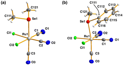 | ||
| Fig. 3 The molecular structures of (a) [RuCl2(CO)3(SeMe2)] (10) and (b) [RuCl2(CO)3(SeMePh)] (11). The anisotropic displacement parameters have been given at 50% probability level. | ||
The bond parameters for 10 and 11 are as expected. The stronger trans-influence of selenium compared to that of chlorine results in the bond length Ru1–C3 to be longer than those of Ru1–C1 and Ru1–C2 [1.944(5) vs. 1.895(4)–1.903(5) Å and 1.946(3) vs. 1.892(3)–1.901(3) Å in 10 and 11, respectively]. Consequently, C3–O3 is somewhat shorter than C1–O1 and C2–O2 in case of both complexes, though the difference is not statistically significant.
The route of the reaction of [RuCl2(CO)3]2 and ERR′ (E = S, Se, Te; R, R′ = Me, Ph)
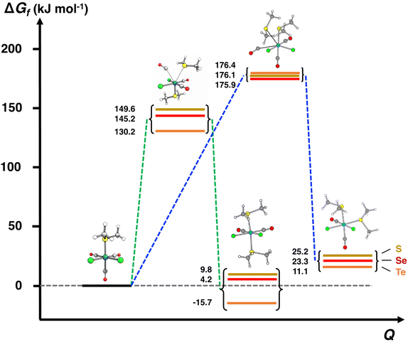
The PBE0-D3/def2-TZVP scans of the reaction surfaces are exemplified by the reaction of [RuCl2(CO)3]2 and EMe2, which are shown in Fig. 4 for the reaction in THF and in Fig. 5 for the reaction in CH2Cl2. The energetics of the possible partial reactions and the activation energies in both solvents are shown in Table 2.
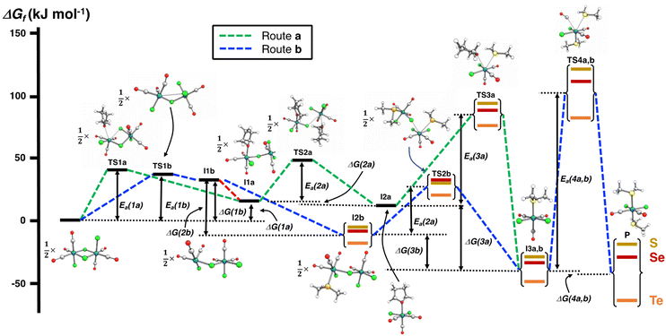 | ||
| Fig. 4 PBE0-D3/def2-TZVP energy profiles of two alternative routes of the reaction of [RuCl2(CO)3]2 and EMe2 (E = S, Se, Te) in THF. The numerical values of the energetics are shown in Table 2. | ||
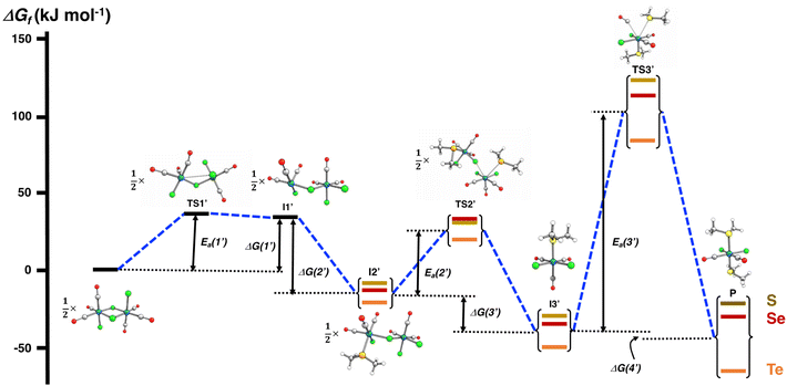 | ||
| Fig. 5 PBE0-D3/def2-TZVP energy profile of the reaction of [RuCl2(CO)3]2 and EMe2 (E = S, Se, Te) in CH2Cl2. | ||
| Reaction | Gibbs energy (kJ mol−1) | |||
|---|---|---|---|---|
| E = S | E = Se | E = Te | ||
| a See Fig. 4. b See Fig. 5. | ||||
| [RuCl 2 (CO) 3 ] 2 + EMe 2 in THF | ||||
| Route a | ||||
| Individual reaction steps | ||||
| ½[RuCl2(CO)3]2 + ½THF ⇄ ½[Ru(THF)Cl(CO)3(μ-Cl)RuCl2(CO)3] (I1a) | ΔG(1a) | 15.1 | 15.1 | 15.1 |
| ½[Ru(THF)Cl(CO)3(μ-Cl)RuCl2(CO)3] (I1a) + ½THF ⇄ [RuCl2(CO)3(THF)] (I2a) | ΔG(2a) | −3.6 | −3.6 | −3.6 |
| [RuCl2(CO)3(THF)] (I2a) + EMe2 ⇄ [RuCl2(CO)3(EMe2)] (I3a,b) + THF | ΔG(3a) | −40.8 | −45.9 | −60.6 |
| [RuCl2(CO)3(EMe2)] (I3a,b) + EMe2 ⇄ [RuCl2(CO)2(EMe2)2] (P) + CO | ΔG(4a,b) | 9.8 | 4.2 | −15.7 |
| Transition states | ||||
| ½[RuCl2(CO)3]2 + ½THF ⇄ ½TS1a | E a(1a) | 40.2 | 40.2 | 40.2 |
| ½[Ru(THF)Cl(CO)3(μ-Cl)RuCl2(CO)3] (I1a) + THF ⇄ ½TS2a | E a(2a) | 32.3 | 32.3 | 32.3 |
| [RuCl2(CO)3(THF)] + EMe2 ⇄ TS3a | E a(3a) | 81.5 | 76.1 | 63.9 |
| [RuCl2(CO)3(EMe2)] + EMe2 ⇄ TS4a,b | E a(4a,b) | 149.6 | 145.2 | 130.2 |
| Route b | ||||
| Individual reaction steps | ||||
| ½[RuCl2(CO)3]2 ⇄ ½[RuCl(CO)3(μ-Cl)RuCl2(CO)3] (I1b) | ΔG(1b) | 33.7 | 33.7 | 33.7 |
| ½[RuCl(CO)3(μ-Cl)RuCl2(CO)3] (I1b) + ½EMe2 ⇄ ½[Ru(EMe2)Cl(CO)3(μ-Cl)RuCl2(CO)3] (I2b) | ΔG(2b) | −41.9 | −45.7 | −54.7 |
| ½[Ru(EMe2)Cl(CO)3(μ-Cl)RuCl2(CO)3] (I2b) + ½EMe2 ⇄ [RuCl2(CO)3(EMe2)] (I3a,b) | ΔG(3b) | −21.0 | −22.3 | −28.0 |
| [RuCl2(CO)3(EMe2)] (I3a,b) + EMe2 ⇄ [RuCl2(CO)2(EMe2)2] (P) + CO | ΔG(4a,b) | 9.7 | 4.2 | −15.7 |
| Transition states | ||||
| ½[RuCl2(CO)3]2 ⇄ ½TS1b | E a(1b) | 36.4 | 36.4 | 36.4 |
| ½[Ru(EMe2)Cl(CO)3(μ-Cl)RuCl2(CO)3] (I2b) + ½EMe2 ⇄ ½TS2b | E a(2b) | 36.5 | 41.7 | 38.2 |
| ½[RuCl2(CO)3(EMe2)] + ½EMe2 ⇄ TS4a,b | E a(4a,b) | 149.6 | 145.2 | 130.2 |
| [RuCl 2 (CO) 3 ] 2 + EMe 2 in CH 2 Cl 2 | ||||
| Individual reaction steps | ||||
| ½[RuCl2(CO)3]2 ⇄ ½[RuCl(CO)3(μ-Cl)RuCl2(CO)3] (I1′) | ΔG(1′) | 33.1 | 33.1 | 33.1 |
| ½[RuCl(CO)3(μ-Cl)RuCl2(CO)3] (I1′) + ½EMe2 ⇄ ½[Ru(EMe2)Cl(CO)3(μ-Cl)RuCl2(CO)3] (I2′) | ΔG(2′) | −41.4 | −45.2 | −54.2 |
| ½[Ru(EMe2)Cl(CO)3(μ-Cl)RuCl2(CO)3] (I2′) + ½EMe2 ⇄ [RuCl2(CO)3(EMe2)] (I3′) | ΔG(3′) | −21.4 | −22.7 | −28.4 |
| [RuCl2(CO)3(EMe2)] (I3′) + EMe2 ⇄ [RuCl2(CO)2(EMe2)2] (P) + CO | ΔG(4′) | 7.8 | 4.5 | −15.3 |
| Transition states | ||||
| ½[RuCl2(CO)3]2 ⇄ ½TS1′ | E a(1′) | 35.8 | 35.8 | 35.8 |
| ½[Ru(EMe2)Cl(CO)3(μ-Cl)RuCl2(CO)3] (I2′) + ½EMe2 ⇄ ½TS2′ | E a(2′) | 36.6 | 41.2 | 37.6 |
| ½[RuCl2(CO)3(EMe2)] + ½EMe2 ⇄ TS3′ | E a(3′) | 149.6 | 144.9 | 130.2 |
The reaction in THF can be considered to take place following two different routes, which are indicated in Fig. 4. The route a, which consists of reaction intermediates I#a (# = the ordinal number along the reaction coordinate; 1–3) and the transition states TS#a (# = 1–4) that are connected by green dashed lines, represents the reaction, in which the THF molecule first coordinates to one of the two ruthenium centres in [RuCl2(CO)3]2 leading to the cleavage of the bond between this ruthenium and one bridging chlorido ligand. The second THF molecule then coordinates to the neighbouring ruthenium centre and leads to the cleavage of the bond between the remaining bridging chlorido ligand and ruthenium. This results in the formation of mononuclear [RuCl2(CO)3(THF)]. The activation barriers in these two steps (40.2 and 32.3 kJ mol−1 for TS1a and TS2a, respectively; see Table 2) are relatively low, and this part of the reaction is expected to be rapid even at room temperature.
The third step involves the substitution of the THF ligand by EMe2. It can be seen from Fig. 4 and Table 2 that the activation barrier is significantly higher than in the two first steps (81.5, 76.1, and 63.9 kJ mol−1 for SMe2, SeMe2, and TeMe2, respectively). Interestingly, the [RuCl2(CO)3(EMe2)] complexes thus formed are very stable. The final step leading to the formation of the end-products cct-[RuCl2(CO)2(SeMe2)2] (P) is the substitution of CO by EMe2. The activation barriers for this step are the highest in case of all reactions (149.6–130.2 kJ mol−1, see Table 2).
Route b (reaction intermediates I#b and the transition states TS#b) represents the reaction path, in which the thermal energy results in the cleavage of the bridging Ru–Cl bond without coordination to the solvent THF. The intermediate I1b shows a very shallow local minimum. When EMe2 is introduced, the intermediate I2b is formed without an activation barrier. It should be noted, however, that THF can also react with I1b in a similar fashion to other chalcogenides without the activation barrier, which would result in the formation of [RuCl(CO)3(THF)(μ-Cl)RuCl2(CO)3], that is identical to I1a (connected by a red dashed line; see Fig. 4).
Attempts to find a transition state for the concerted coordination of EMe2 and the cleavage of the bridging Ru–Cl leading to the direct formation of [RuCl(CO)3(EMe2)(μ-Cl)RuCl2(CO)3] (intermediate I2b) from [RuCl2(CO)3]2 resulted in transition states that were much higher in energy. This renders the concerted reaction mechanism unlikely.
The experimental support for the coordination of the solvent to the two ruthenium atoms in [RuCl2(CO)3]2 comes from the observation that some reaction batches afforded colourless crystals, which were shown by crystal structure determination to be [RuCl2(CO)3(THF)] (I2a; see Fig. 4). The structure of I2a has been reported previously by Gray and Duffey.21 The detection of this complex in some reaction batches indicates that THF indeed coordinates to [RuCl2(CO)3]2, but the formation of I1a could equally well follow either the route a or route b, or both.
The addition of the second EMe2 to [RuCl(CO)3(EMe2)(μ-Cl)RuCl2(CO)3] (I2b) generates I3b, which is identical to I3a. The last step involving the substitution of CO by EMe2 yielding P is identical in both alternative routes.
The comparison of the energetics in the routes a and b in Fig. 4 and Table 2 indicates that the thermal opening of the bridging Ru–Cl bond in [RuCl2(CO)3]2 is competitive to the initial coordination of the solvent, and the addition of EMe2 to the free coordination site results in [RuCl(CO)3(EMe2)(μ-Cl)RuCl2(CO)3] (intermediate I2b), which lies lower in energy than [RuCl(CO)3(THF)(μ-Cl)RuCl2(CO)3] (intermediate I1a) or [RuCl2(CO)3(THF)] (intermediate I2a). There is a significantly higher energy barrier from I2a to I3a,b than from I2b to I3a,b. The last step in the reaction is identical in both alternative pathways and shows the highest energy barrier. It is the rate-determining step of the overall reaction.
When the reaction is carried out in CH2Cl2, the coordination of the solvent to [RuCl2(CO)3]2 does not take place. The energy profile of this reaction is shown in Fig. 5, and the PBE0-D3/def2-TZVP energetics of the individual reaction steps are shown in Table 2. All intermediates (I1′–I3′) and the end-product P again show local minima with only real frequencies, and all transition states (TS1′–TS3′) show only one imaginary frequency each along the reaction coordinate.
It can be seen from Fig. 5 that the reaction profile in CH2Cl2 is virtually identical with that shown for the reaction in THF without solvent coordination (cf. route b in Fig. 4). The first intermediate I1′ again lies in the shallow local energy minimum and the introduction of the first methyl chalcogenide to the unsaturated five-coordinate ruthenium centre in I1′ proceeds without the activation barrier. The addition of the second methyl chalcogenide ligand proceeds according to the interchange mechanism, with the activation barrier rather low and of the same order of magnitude as in the reaction in THF. Therefore, the cleavage of the bridging Ru–Cl bonds is also expected to take rapidly place even at room temperature.
The activation barriers in the final substitution step (CO substituted by the second EMe2) are almost identical regardless of the solvent (see Table 2) and determine the overall rate of the reaction. It can be inferred that the main factor in the observed faster reaction rate in THF compared to that in CH2Cl2 is due to the higher boiling point of THF (the boiling point of THF is 66 °C and that of CH2Cl2 is 40 °C).
The composition of the different reaction mixtures has been monitored as a function of time by 13C{1H}, 77Se, and 125Te NMR spectroscopy, as appropriate. This is exemplified by the reaction of SeMe2 with [RuCl2(CO)3]2 in CH2Cl2 (see Fig. 6).
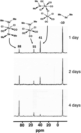 | ||
| Fig. 6 The 77Se NMR spectra of the reaction mixture of SeMe2 and [RuCl2(CO)3]2 in CH2Cl2 upon reflux. | ||
The isolation and structural and spectroscopic characterization of both [RuCl2(CO)3(SeMe2)] (10; 77Se chemical shift 55 ppm) and cct-[RuCl2(CO)2(SeMe2)2] (5cct; 77Se chemical shift 88 ppm) provide experimental indication that the reaction leading to the formation cct-[RuCl2(CO)2(ERR′)2] proceeds via the intermediate formation of [RuCl2(CO)3(ERR′)] (see Fig. 6). The resonance at 41 ppm, which was detected in the early stages of the reaction, reduced in intensity as a function of time and is tentatively assigned to [Ru(EMe2)Cl(CO)3(μ-Cl)RuCl2(CO)3] (I2b). While this species has not been isolated and unambiguously identified, the PBE0-D3/def2-TZVP energetics indicate that the formation of I2b is favourable. Its 77Se NMR chemical shift also shows a reasonable value. Furthermore, the observed decrease of intensity of resonance at 41 ppm as the reaction progresses is consistent with the resonance arising from an intermediate species like I2b.
The formation of [RuCl2(CO)3(ERR′)] (E = S, Se, Te; R, R′ = Me, Ph) could also be detected in some other reaction batches by NMR spectroscopy. The 13C{1H} (see Fig. S6 in ESI†) and 77Se NMR spectra of [RuCl2(CO)3(SeMePh)] (11) were recorded from redissolved crystals isolated from the reaction mixture (the spectroscopic assignment is discussed in section 4.4 in ESI†). The 13C resonances of the respective reaction of SMePh and [RuCl2(CO)3]2 were assigned from the 13C{1H} spectrum recorded directly from the reaction solution (see Fig. S4 in ESI†) by comparison to the 13C{1H} spectrum recorded for the redissolved crystals of cct-[RuCl2(CO)2(SMePh)2] (2cct) (see Fig. S7 in ESI†). The reaction mixture of [RuCl2(CO)3]2 and TeMePh showed a 125Te NMR resonance at 374 ppm, which disappeared in a few days. Taking into account the reported approximate relationship between 125Te and 77Se chemical shifts in related alkyl tellurides [δ(Te) = (1.8)·δ(Se)22], it can be concluded that the assignment of this resonance to [RuCl2(CO)3(TeMePh)] is consistent with the observed 77Se chemical shift of 192 pm for [RuCl2(CO)3(SeMePh)].
 | (2) |
The energy profiles and the computed energy values in the reaction involving EMe2 are shown in Fig. 7.
The calculations clearly show that formation of ccc-[RuCl2(CO)2(EMe2)2] is less likely than that of cct-[RuCl2(CO)2(EMe2)2]. It can be seen from Fig. 7 that the activation energies of the transition states leading to the ccc-isomer are ca. 30 kJ mol−1 higher than those leading to the formation of the cct-isomer. It can therefore be expected that the rate of formation of the ccc-isomer is significantly slower than that of cct-isomer even when refluxing in THF. Furthermore, the Gibbs energy changes in this reaction step in case of all three complexes indicate that the formation of the ccc-complexes is more unfavourable than that of the cct-complex.
The PBE0-D3/def2-TZVP Gibbs energy changes in the rate-determining final reaction step have been compared in Fig. 8 for the formation of both the cct- and ccc-isomers. There are two trends. This reaction step becomes more favourable, as the chalcogen atom becomes heavier. The reactions, however, are exergonic only in the case of telluroethers. By contrast, with the bulkier and more strongly electron withdrawing organic substituents, the reaction becomes less favourable. These energy trends are also reflected in the yields of the products. The telluroethers can be isolated in good yields, whereas the yields go steadily down, as the chalcogen is changed to a lighter one. All energy values seem to be virtually identical in both solvents.
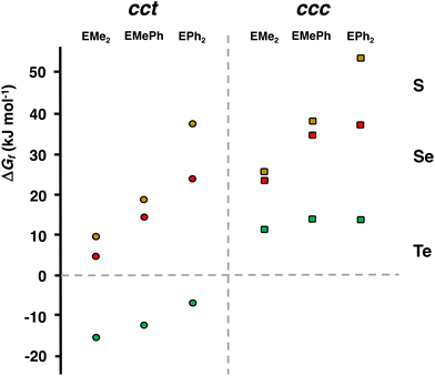 | ||
| Fig. 8 The comparison of the PBE0-D3/def2-TZVP Gibbs energy changes in the rate-determining reaction step [RuCl2(CO)3(EMe2)] → cct-[RuCl2(CO)2(EMe2)2] and [RuCl2(CO)3(EMe2)] → ccc-[RuCl2(CO)2(EMe2)2] (see Tables 2 and S6 in ESI†). | ||
It can clearly be seen in Fig. 8 that the final step for the formation of the ccc-isomer is significantly less favourable than that for the formation of the cct-isomer.
The prolonged stirring of [RuCl2(CO)3]2 and SeMe2 at room temperature yielded two additional resonances at 114 and 97 ppm, which were not detected under reflux. The intensities of both resonances increased as a function of time, but they showed a constant intensity ratio of 1![[thin space (1/6-em)]](https://www.rsc.org/images/entities/char_2009.gif) :
:![[thin space (1/6-em)]](https://www.rsc.org/images/entities/char_2009.gif) 2, respectively. While it is not possible to assign them unequivocally, a plausible explanation is that they are due to the formation of mer-[RuCl2(CO)(SeMe2)3].
2, respectively. While it is not possible to assign them unequivocally, a plausible explanation is that they are due to the formation of mer-[RuCl2(CO)(SeMe2)3].
We have reported earlier that the mer-[RuCl2(CO){Te(CH2SiMe3)2}3] complex shows two 125Te NMR resonances at 322 and 278 ppm with the respective intensity ratio of 1![[thin space (1/6-em)]](https://www.rsc.org/images/entities/char_2009.gif) :
:![[thin space (1/6-em)]](https://www.rsc.org/images/entities/char_2009.gif) 2. They are deshielded from the single resonance at 268 ppm of cct-[RuCl2(CO)2{Te(CH2SiMe3)2}2].9 The crystal structure determination showed mer-[RuCl2(CO){Te(CH2SiMe3)2}3] to be the mer(1) isomer (see Chart 1) and the chemical shifts can be rationalized by the relative trans-influence strengths of the ligands (Cl < ERR′ < CO).
2. They are deshielded from the single resonance at 268 ppm of cct-[RuCl2(CO)2{Te(CH2SiMe3)2}2].9 The crystal structure determination showed mer-[RuCl2(CO){Te(CH2SiMe3)2}3] to be the mer(1) isomer (see Chart 1) and the chemical shifts can be rationalized by the relative trans-influence strengths of the ligands (Cl < ERR′ < CO).
The resonances at 114 and 97 ppm are also deshielded relative to that of cct-[RuCl2(CO)2(SeMe2)2] (4cct) and are in the expected region for mer-[RuCl2(CO)(SeMe2)3]. The higher-intensity resonance appears at high field to that of the lower-intensity resonance and implies the presence of the mer(1) isomer of [RuCl2(CO){SeMe2}3].
Conclusions
The trends in the formation, stereochemistry, and isomerism of the series of [RuCl2(CO)2(ERR′)2] (E = S, Se, Te; R, R′ = Me, Ph) complexes have been explored both in THF and CH2Cl2. The products and their yields were rather similar in both solvents, but the reactions were significantly faster in THF than in CH2Cl2. The highest yields were observed for the telluroether complexes, and the yields decreased with lighter chalcogenoethers. The computed PBE0-D3/def2-TZVP energetics were consistent with these observations.The crystal structures of [RuCl2(CO)2(SMePh)2], [RuCl2(CO)2(SeMe2)2], [RuCl2(CO)2(SePh2)2], and [RuCl2(CO)2(TeMePh)2] all show that the complexes are cct-isomers [cis(Cl), cis(CO), trans(ERR′)] in agreement with previous data.6–9 PBE0-D3/def2-TZVP calculations of the different isomers of all [RuCl2(CO)2(ERR′)2] complexes have shown that the stabilities of the complexes follow the order cct > ccc > tcc > ttt ≈ ctc. This ordering is consistent with the relative trans-influence strengths of the different ligands involved in the coordination spheres. Steric effects seem to play only a little role.
The PBE0-D3/def2-TZVP calculations of the reaction pathways show that the energetics are independent of the nature of the solvent. The last step to [RuCl2(CO)2(ERR′)2] involving the substitution of one CO ligand of the intermediate [RuCl2(CO)3(ERR′)] by the second ERR′ is the rate-determining step in all reactions. Since the syntheses have been carried out upon reflux, the observed faster reaction in THF compared to that in CH2Cl2 is due to the higher boiling point of the former solvent. At room temperature the reactions in both solvents proceed very slowly.
The computations also show that when the reaction is carried out in THF, the initial formation of [RuCl2(CO)3(THF)] is possible and the reaction would then proceed with the substitution of THF by ERR′. It turns out, however, that the formation of the THF complex is not necessary for the dissociation of the dinuclear ruthenium carbonyl chloride starting material. Thermal energy at room temperature is sufficient to cleave the bridging Ru–Cl bonds in [RuCl2(CO)3]2, which can then react further with ERR′. This mechanism is possible also in non-coordinating CH2Cl2.
Conflicts of interest
There are no conflicts to declare.Acknowledgements
We are grateful for the helpful discussions by Prof. Markku Ahlgrén and Dr Ludmila Vigo. Financial support from Finnish Cultural Foundation Lapland Regional Fund, The Finnish Concordia Fund, and Emil Aaltonen Foundation (M. T.), as well as the generous provision of computational resources by Prof. Heikki Tuononen (University of Jyväskylä) (J. M. R.) are also gratefully acknowledged.References
- (a) K. Ling, F. Men, W.-C. Wang, Y.-Q. Zhou, H.-W. Zhang and D.-W. Ye, J. Med. Chem., 2018, 61, 2611–2615 CrossRef CAS; (b) A. C. Kautz, P. C. Kunz and C. Janiak, Dalton Trans., 2016, 45, 18045–18063 RSC; (c) S. Garcia-Gallego and G. J. L. Bernardes, Angew. Chem., Int. Ed., 2014, 53, 9712–9721 CrossRef CAS; (d) D. Wang, E. Viennois, K. Ji, K. Damera, A. Draganov, Y. Zheng, C. Dai, D. Merlin and B. Wang, Chem. Commun., 2014, 50, 15890–15893 RSC; (e) C. C. Romão, W. A. Blätter, J. D. Seixas and G. J. L. Bernardes, Chem. Soc. Rev., 2012, 41, 3571–3583 RSC.
- (a) A. Gallen, S. Orgué, G. Muller, E. C. Escudero-Adán, A. Riera, X. Verdaguer and A. Grabulosa, Dalton Trans., 2018, 47, 5366–5379 RSC; (b) S. Giboulot, S. Baldino, M. Ballico, H. G. Nedden, D. Zuccaccia and W. Baratta, Organometallics, 2018, 37, 2136–2146 CrossRef CAS; (c) G. Tamasi, A. Merlino, F. Scaletti, P. Heffeter, A. A. Legin, M. A. Jakupec, W. Berger, L. Messori, B. K. Keppler and R. Cini, Dalton Trans., 2017, 46, 3025–3040 RSC; (d) R. Tatikonda and M. Haukka, Acta Crystallogr., Sect. E: Crystallogr. Commun., 2017, 73, 556–559 CrossRef CAS PubMed; (e) J. D. Seixas, M. Chaves-Ferreira, D. Montes-Grajales, A. M. Gonçalves, A. R. Marques, L. M. Saraiva, J. Olivero-Verbel, C. C. Romão and G. J. L. Bernardes, Chem. – Eur. J., 2015, 21, 14708–14712 CrossRef CAS; (f) C. W. Machan, M. D. Sampson and C. P. Kubiak, J. Am. Chem. Soc., 2015, 137, 8564–8571 CrossRef CAS; (g) L. V. Graux, M. Giorgi, G. Buono and H. Clavier, Organometallics, 2015, 34, 1864–1871 CrossRef CAS; (h) G. Tamasi, A. Carpini, D. Valensin, L. Messori, A. Pratesi, F. Scaletti, M. Jakupec, B. Keppler and R. Cini, Polyhedron, 2014, 81, 227–237 CrossRef CAS; (i) M. Toganoh, H. Matsuo, A. Sato, Y. Hirashima and H. Furuta, Inorg. Chem., 2013, 52, 9613–9619 CrossRef CAS PubMed; (j) S. J. Carrington, I. Chakraborty, J. R. Alvarado and P. K. Mascharak, Inorg. Chim. Acta, 2013, 407, 121–125 CrossRef CAS PubMed; (k) T. Ghatak, A. Sinha, S. M. W. Rahaman and J. K. Bera, Inorg. Chim. Acta, 2011, 372, 94–99 CrossRef CAS; (l) S. Fleischhauer, K. Eichele, I. Schellenberg, R. Pöttgen and L. Wesemann, Organometallics, 2011, 30, 3200–3209 CrossRef CAS; (m) M. Majumdar, A. Sinha, T. Ghatak, S. K. Patra, N. Sadhukhan, S. M. W. Rahaman and J. K. Bera, Chem. – Eur. J., 2010, 16, 2574–2585 CrossRef CAS PubMed.
- G. Balducci, E. Iengo, N. Demitri and E. Alessio, Eur. J. Inorg. Chem., 2015, 4296–4311 CrossRef CAS , and references therein.
- (a) S. G. Murray and F. R. Hartley, Chem. Rev., 1981, 81, 365–414 CrossRef CAS; (b) H. J. Gysling, Coord. Chem. Rev., 1982, 42, 133–244 CrossRef CAS; (c) E. G. Hope and W. Levason, Coord. Chem. Rev., 1993, 122, 109–170 CrossRef CAS; (d) W. Levason and G. Reid, J. Chem. Soc., Dalton Trans., 2001, 2953–2960 RSC; (e) W. Levason, S. D. Orchard and G. Reid, Coord. Chem. Rev., 2002, 225, 159–199 CrossRef CAS; (f) W. Levason and G. Reid, J. Chem. Res., 2002, 467–472, 1001–1022 Search PubMed.
- (a) A. K. Singh, P. K. Raghavendra, G. Singh and S. Bali, Phosphorus, Sulfur Silicon Relat. Elem., 2005, 180, 903–170 CrossRef; (b) V. K. Jain and R. S. Chauhan, Coord. Chem. Rev., 2016, 306, 270–301 CrossRef CAS; (c) R. S. Chauhan and N. Shivran, RSC Adv., 2017, 7, 55175–55198 RSC.
- (a) W. Hieber and P. John, Chem. Ber., 1970, 103, 2161–2177 CrossRef CAS; (b) P. John, Chem. Ber., 1970, 103, 2178–2196 CrossRef CAS.
- M. Taimisto, R. Oilunkaniemi, R. S. Laitinen and M. Ahlgrén, Z. Naturforsch., 2003, 58b, 959–964 CrossRef.
- R. Oilunkaniemi, R. S. Laitinen and M. Ahlgrén, Inorg. Chem. Commun., 2000, 3, 8–10 CrossRef CAS.
- L. Vigo, M. J. Poropudas, R. Oilunkaniemi and R. S. Laitinen, J. Organomet. Chem., 2008, 693, 557–563 CrossRef CAS.
- R. C. Burns, M. J. Collins, R. J. Gillespie and G. J. Schrobilgen, Inorg. Chem., 1986, 25, 4465–4469 CrossRef CAS.
- M. J. Collins and G. J. Schrobilgen, Inorg. Chem., 1985, 24, 2608–2614 CrossRef CAS.
- (a) G. M. Sheldrick, Acta Crystallogr., Sect. A: Found. Crystallogr., 2008, 64, 112–122 CrossRef CAS; (b) G. M. Sheldrick, Acta Crystallogr., Sect. A: Found. Adv., 2015, 71, 3–8 CrossRef.
- D. H. O'Brien, N. Dereu, C.-K. Huang, K. J. Irgolic and F. F. Knapp, Jr., Organometallics, 1983, 2, 305–307 CrossRef.
- E. G. Hope, T. Kemmit and W. Levason, Organometallics, 1988, 7, 78–83 CrossRef CAS.
- M. J. Frisch, G. W. Trucks, H. B. Schlegel, G. E. Scuseria, M. A. Robb, J. R. Cheeseman, G. Scalmani, V. Barone, G. A. Petersson, H. Nakatsuji, X. Li, M. Caricato, A. V. Marenich, J. Bloino, B. G. Janesko, R. Gomperts, B. Mennucci, H. P. Hratchian, J. V. Ortiz, A. F. Izmaylov, J. L. Sonnenberg, D. Williams-Young, F. Ding, F. Lipparini, F. Egidi, J. Goings, B. Peng, A. Petrone, T. Henderson, D. Ranasinghe, V. G. Zakrzewski, J. Gao, N. Rega, G. Zheng, W. Liang, M. Hada, M. Ehara, K. Toyota, R. Fukuda, J. Hasegawa, M. Ishida, T. Nakajima, Y. Honda, O. Kitao, H. Nakai, T. Vreven, K. Throssell, J. A. Montgomery, Jr., J. E. Peralta, F. Ogliaro, M. J. Bearpark, J. J. Heyd, E. N. Brothers, K. N. Kudin, V. N. Staroverov, T. A. Keith, R. Kobayashi, J. Normand, K. Raghavachari, A. P. Rendell, J. C. Burant, S. S. Iyengar, J. Tomasi, M. Cossi, J. M. Millam, M. Klene, C. Adamo, R. Cammi, J. W. Ochterski, R. L. Martin, K. Morokuma, O. Farkas, J. B. Foresman and D. J. Fox, Gaussian 16, Rev. C.01, Gaussian, Inc., 2016 Search PubMed.
- (a) J. P. Perdew, K. Burke and M. Ernzerhof, Phys. Rev. Lett., 1996, 77, 3865–3868 CrossRef CAS PubMed; Erratum, Phys. Rev. Lett., 1997, 78, 1396. (b) J. P. Perdew, M. Ernzerhof and K. Burke, J. Chem. Phys., 1996, 105, 9982–9985 CrossRef CAS; (c) C. Adamo and V. Barone, J. Chem. Phys., 1999, 110, 6158–6170 CrossRef CAS.
- (a) F. Weigend, M. Haser, H. Patzelt and R. Ahlrichs, Chem. Phys. Lett., 1998, 294, 143–152 CrossRef CAS; (b) F. Weigend and R. Ahlrichs, Phys. Chem. Chem. Phys., 2005, 7, 3297–3305 RSC.
- (a) V. Barone and M. Cossi, J. Phys. Chem. A, 1998, 102, 1995–2001 CrossRef CAS; (b) M. Cossi, N. Rega, G. Scalmani and V. Barone, J. Comput. Chem., 2003, 24, 669–681 CrossRef CAS PubMed.
- (a) S. Grimme, J. Antony, S. Ehrlich and H. Krieg, J. Chem. Phys., 2010, 132, 154104 CrossRef PubMed; (b) L. A. Burns, A. Vazquez-Mayagoitia, B. G. Sumpter and C. D. Sherrill, J. Chem. Phys., 2011, 134, 084107 CrossRef; (c) S. Grimme, S. Ehrlich and L. Goerigk, J. Comput. Chem., 2011, 32, 1456–1465 CrossRef CAS.
- J. Emsley, The Elements, 3rd. Ed, Clarendon Press, Oxford, 1998, 292 pp Search PubMed.
- G. M. Gray and C. H. Duffey, Acta Crystallogr., Sect. C: Cryst. Struct. Commun., 1996, 52, 861–863 CrossRef.
- H. C. E. McFarlane and W. McFarlane, J. Chem. Soc., Dalton Trans., 1973, 2416–2418 RSC.
Footnotes |
| † Electronic supplementary information (ESI) available: Synthetic details, crystal structure determinations of 2cct, 4cct, 6cct, 8cct, 10, and 11, tentative molecular structure of 8cct, assignment of NMR spectra, computational results. CCDC 2152613–2152617 and 2152619. For ESI and crystallographic data in CIF or other electronic format see DOI: https://doi.org/10.1039/d2dt02018a |
| ‡ Present address: NutriAg Ltd, 62 Arrow Rd Toronto, ON, M9M 2L8 Canada. |
| This journal is © The Royal Society of Chemistry 2022 |

