A high-performance C@Na5V12O32 nanowire electrode derived from the reconstruction of carbon quantum dots†
Zhengying
Zhang
a,
Dong
Fang
 *a,
Jianhong
Yi
a,
Hua
Yang
a,
Jian
Liu
b,
Feng
Liu
b,
Anvar
Khamidov
c and
Olim
Ruzimuradov
cd
aFaculty of Materials Science and Engineering, Kunming University of Science and Technology, Kunming, 650093, China. E-mail: mfangdong@knust.edu.cn
bYunnan Precious Metals Lab Co., Ltd., Kunming, Yunnan 650106, China
cDepartment of Chemistry, National University of Uzbekistan, 100174 Tashkent, Uzbekistan
dTurin Polytechnic University in Tashkent, 100095 Tashkent, Uzbekistan
First published on 6th June 2024
Abstract
Vanadate electrodes are potential candidates for lithium-ion batteries (LIBs) due to their large theoretical specific capacity. However, their easy dissolution in the electrolyte, large structural changes, low conductivity and capacity decay during cycling hinder their further application. Herein, a lithium-ion battery electrode of Na5V12O32 (NVO) nanowires covered with a carbon film and formed by the reconstruction of carbon quantum dots (CDs) was obtained using an in situ capping strategy. Remarkably, the carbon film could prevent direct contact between the NVO nanowires and the electrolyte, thus slowing down the occurrence of side reactions and avoiding the dissolution of the NVO nanowires. Among the electrodes treated at different temperatures, the C@NVO-400 electrode exhibits high capacity and excellent cycling stability as the electrode of LIBs, with a discharge specific capacity of 779.1 and 315.5 mAh g−1 after 400 and 1000 cycles at a current density of 0.1 and 2 A g−1, respectively. An in situ coating strategy is proposed here to contribute to the further development of coated vanadate electrodes for high-performance LIBs.
1. Introduction
Lithium-ion batteries (LIBs) are among the most attractive energy storage devices due to their high energy density, long service life and low self-discharge rate, and they are widely used in portable electronic products such as cell phones, notebook computers and digital cameras.1,2 They are also considered as the power source for electric vehicles and stationary energy storage systems. Graphite electrodes have been widely used in commercialized LIBs, but their relatively low theoretical specific capacity (372 mA h g−1) cannot meet the market demand for future large-scale energy storage devices.3 Therefore, new lithium battery electrode materials with larger specific capacity and higher power density should be developed urgently. In recent years, transition metal vanadates have become highly competitive and promising electrode materials due to their high specific capacities. For example, Co3O4@Co3V2O8,4 Co2V2O7,5 Zn2V2O7,6 Zn3V3O8/C,7 NiCo2V2O8![[thin space (1/6-em)]](https://www.rsc.org/images/entities/char_2009.gif) 8 and Ni3V2O8
8 and Ni3V2O8![[thin space (1/6-em)]](https://www.rsc.org/images/entities/char_2009.gif) 9 have been reported as electrode materials for LIBs. Among metal vanadates, sodium vanadate has become a key material due to its small molecular weight and relatively high unit specific capacity,10 while vanadates as electrode materials for lithium batteries suffer from capacity degradation because of dissolution, poor multiplication performance and low electrical conductivity.11
9 have been reported as electrode materials for LIBs. Among metal vanadates, sodium vanadate has become a key material due to its small molecular weight and relatively high unit specific capacity,10 while vanadates as electrode materials for lithium batteries suffer from capacity degradation because of dissolution, poor multiplication performance and low electrical conductivity.11
Consequently, the preparation of vanadate electrodes with high capacity and good cycling performance is still a challenge. Numerous studies have shown that the coating of a conductive carbon material can effectively accommodate the volume fluctuation of the material during the charging and discharging processes, alleviate the side reactions of the electrolyte and the active substance, maintain the stability of the electrode structure and thus improve the cycle life of LIBs. Currently, various carbon materials including hollow nanostructured carbon,12 carbon nanorods,13 carbon nanofibers,14 carbon nanosheets,15 porous carbon,16 hard carbon,17 graphene18 and heteroatom-doped carbon materials19 are the most popular coating materials. Although ordinary carbon cladding materials have improved the performance of electrode materials, the carbon layer suffers from inhomogeneity and incomplete coverage. Carbon quantum dots (CDs) are a class of zero-dimensional carbon nanomaterials that exhibit a quasi-spherical morphology and abundant active sites, while they exhibit poor conductivity.20 CDs (3–5 nm) without aggregation can achieve uniform and controllable coating for different materials as they have small sizes. Besides, CDs have great potential as next-generation energy materials.21–23 The voids among CDs may affect the integrity and density of the coating layer, and hence it cannot be used as a solid electrolyte interface (SEI) membrane.
In this work, Na5V12O32 (NVO) nanowires covered with a carbon film are formed by the reconstruction of CDs for the first time using an in situ coating and heat treatment strategy. The homogeneous carbon film can mitigate the occurrence of side reactions and act as a SEI-like membrane. The high degree of graphitization of the carbon layer also increases the conductivity of the composite, facilitating the rapid diffusion of electrons and improving its multiplicity performance. The C@NVO-400 electrode has a discharge specific capacity of 779.1 mA h g−1 after 400 cycles at a current density of 0.1 A g−1, showing excellent cycling stability. This work provides insights into the effects of an SEI-like membrane carbon film constructed from CDs, opening a new avenue for high-capacity electrode materials.
2. Experimental section
2.1. Materials
NH4VO3, NaCl, oxalic acid (H2C2O4·2H2O), hexamethylene tetramine (HMTA) and ethanol anhydrous were purchased from Shanghai Aladdin Biochemical Technology Co., Ltd without any purification. A Ti foil (purity of 99.5%) with a thickness of 0.3 mm was purchased from Guanyue Metal Materials Co. Ltd. The Ti foil was polished with sandpaper and sonicated in an ethanol solution for 15 min to remove surface oil.2.2. Synthesis of pure NVO and C@NVO-X
NVO precursor synthesis: according to our previous paper, NVO was prepared by the hydrothermal method.24 Specifically, 1 mmol NH4VO3, 2 mmol H2C2O4, 6 mmol NaCl, and 0.2 mmol HMTA were added into 17.5 mL of deionized water with constant stirring for five hours to produce a blue-black solution. Subsequently, polished titanium foil was placed in a 50 ml Teflon-lined stainless-steel autoclave, and was heated to 150 °C and kept at this temperature for 1 h. After that, the Ti foil in the solution was collected, washed with deionized water three times, and dried at 60 °C for 12 h to obtain Na5V12O32 nanowires on the Ti foil.2.3. Materials characterization
The morphology of the samples was characterized using a scanning electron microscope (SEM, Hitachi S-4800 at 20 kV) and a transmission electron microscope (TEM, JEOL-2100F at 200 kV). The chemical constituents of the samples were measured by energy-dispersive X-ray spectroscopy (EDS). The crystal structure of the obtained samples was analyzed using an X-ray diffractometer (XRD, Rigaku MiniFlex 600). Raman spectra were recorded using a Horiba Scientific LabRAM HR Evolution. The binding energies of the samples were studied by X-ray photoelectron spectroscopy (XPS, Thermo Scientific, K-Alpha).2.4. Electrochemical measurements
Ti foils loaded with NVO and C@NVO were cut into 14 mm diameter circles to be used as working electrodes, and the weight loading of active species was 0.7–1.2 mg cm−2. 1 M LiPF6 dissolved in ethylene carbonate/ethyl methyl carbonate/dimethyl carbonate (1![[thin space (1/6-em)]](https://www.rsc.org/images/entities/char_2009.gif) :
:![[thin space (1/6-em)]](https://www.rsc.org/images/entities/char_2009.gif) 1
1![[thin space (1/6-em)]](https://www.rsc.org/images/entities/char_2009.gif) :
:![[thin space (1/6-em)]](https://www.rsc.org/images/entities/char_2009.gif) 1 in volume) was used as an electrolyte. The coin-type half-cell (CR2025) assembly was performed in an Ar-filled glove box with water and oxygen concentrations less than 0.1 ppm (Etelux Lab-2000). The constant current charge and discharge tests were carried out using a Neware battery testing system with different current densities in the voltage range of 0.01–3.0 V. The galvanostatic intermittent titration technique (GITT) was recorded at a current density of 100 mA g−1 using the Neware battery testing system in the voltage range of 0.01–3.0 V. Cyclic voltammetry (CV) measurements in a potential window of 0.01–3.0 V (vs. Li+/Li) and electrochemical impedance (EIS) within the frequency range of 0.01 to 100 kHz were obtained using an electrochemical workstation (CorrTest CS350). In situ EIS spectroscopy was performed on a Chenhua electrochemical workstation (CHI-760E) in the frequency range of 0.01 to 100 kHz. The voltage range was 0.01–1.0 V, and the impedance spectra were sampled at 0.02 V intervals.
1 in volume) was used as an electrolyte. The coin-type half-cell (CR2025) assembly was performed in an Ar-filled glove box with water and oxygen concentrations less than 0.1 ppm (Etelux Lab-2000). The constant current charge and discharge tests were carried out using a Neware battery testing system with different current densities in the voltage range of 0.01–3.0 V. The galvanostatic intermittent titration technique (GITT) was recorded at a current density of 100 mA g−1 using the Neware battery testing system in the voltage range of 0.01–3.0 V. Cyclic voltammetry (CV) measurements in a potential window of 0.01–3.0 V (vs. Li+/Li) and electrochemical impedance (EIS) within the frequency range of 0.01 to 100 kHz were obtained using an electrochemical workstation (CorrTest CS350). In situ EIS spectroscopy was performed on a Chenhua electrochemical workstation (CHI-760E) in the frequency range of 0.01 to 100 kHz. The voltage range was 0.01–1.0 V, and the impedance spectra were sampled at 0.02 V intervals.
3. Results and discussion
NVO with a nanowire morphology (Fig. S1†) was synthesized as an electrode according to our previous work,24 and well-dispersed CDs were prepared using a hydroxyl aldehyde condensation reaction. The synthesis route of C@NVO-X is shown in Fig. 1a. Firstly, the NVO nanowires were immersed in CD ethanol solution to form CDs@NVO (Fig. S2†). Then, the CDs@NVO was heat-treated at different temperatures, and the samples were denoted as C@NVO-X, where X denotes the annealing temperature (°C). Fig. S3† shows the TEM images of the as-prepared monodisperse CDs with diameters of 2.0–3.0 nm. In XRD patterns, as displayed in Fig. S4,† the broad peak at 20° of CDs is different from the diffraction spectra of graphitic carbon. The Fourier transform infrared spectrum (FTIR spectrum, Fig. S5†) reveals that the CDs contain rich oxygenous functional groups, such as C![[double bond, length as m-dash]](https://www.rsc.org/images/entities/char_e001.gif) O and C–OH, which might be in favor of its surface functionalization.25 The XRD spectra of NVO and C@NVO-400 are displayed in Fig. 1b. Resulting from the low loading of active materials, NVO and C@NVO-400 exhibit obvious peaks of a Ti foil. Other peaks of NVO are fitted well with Na5V12O32(PDF#24-1156),24 the peak at 48° may belong to the (100) lattice plane of carbon.26,27
O and C–OH, which might be in favor of its surface functionalization.25 The XRD spectra of NVO and C@NVO-400 are displayed in Fig. 1b. Resulting from the low loading of active materials, NVO and C@NVO-400 exhibit obvious peaks of a Ti foil. Other peaks of NVO are fitted well with Na5V12O32(PDF#24-1156),24 the peak at 48° may belong to the (100) lattice plane of carbon.26,27
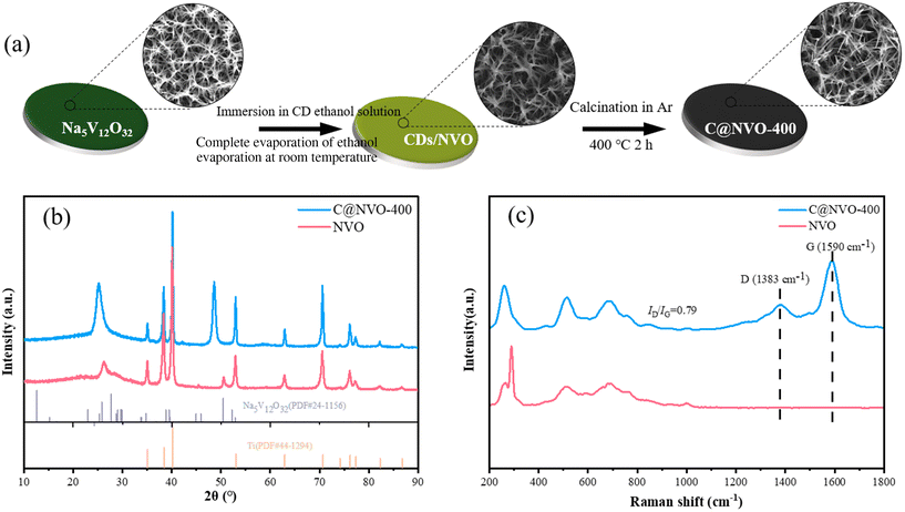 | ||
| Fig. 1 (a) Schematic of the synthesis of C@NVO nanowires. (b) XRD spectra of NVO and C@NVO-400. (c) Raman spectra of NVO and C@NVO-400 nanowires. | ||
To further investigate the internal structure and properties, Raman spectra of NVO and C@NVO-400 were recorded (Fig. 1c). The Raman spectrum of C@NVO-400 has classical vibrational modes (corresponding to the D and G peaks) at 1383 cm−1 and 1590 cm−1, respectively. The ID/IG value of C@NVO-400 is 0.79, and it indicates that the deposition of CDs leads to a high degree of graphitization of C@NVO-400. Graphitic carbon can enhance the electrical conductivity of the electrode material, thus improving its electrochemical performance.28
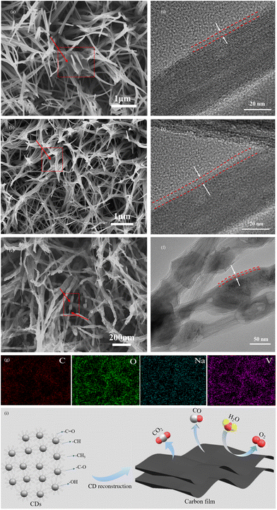
The morphologies of NVO (Fig. S1†), C@NVO-300 (Fig. 2a), C@NVO-400 (Fig. 2b) and C@NVO-500 (Fig. 2c) were observed by SEM. The original nanowire structure of NVO is retained after coating with CDs. As seen in C@NVO-500 (Fig. 2c), the original NVO nanowires can be used as a skeleton for the reconstruction of the coated CDs to in situ form a carbon film, in which the core/shell structure is clearly observed.29,30 In addition, the elements Na, V, O and C distribute uniformly as shown in the EDS-mapping images (Fig. 2g). The TEM results further characterized the microstructure of the C@NVO-X nanocomposites. Fig. 2d–f show that there is a clear film with a few nanometers on the surface of the NVO nanowire skeleton for all C@NVO-X samples. It is noteworthy that the nanowire skeleton started to aggregate and fracture when the annealing temperature rises to 500 °C, which may affect its lithium storage performance. It is hypothesized that the formation of carbon films on the surface of NVO nanowires originates from the reconstruction of CDs (Fig. 2h). CDs have typical hydrogen bonding modules,31–33 which play an important role in the control of self-assembly of complex molecules due to its directionality, selectivity and synergism. Thanks to the hydrogen bonding, the in situ arrangement of CDs along the two-dimensional direction can realize the controlled assembly of 2D carbon films during the annealing process.34
The elemental analysis of C@NVO-400 was carried out by XPS. The survey spectrum of C@NVO-400 is presented in Fig. S6,† which confirms the presence of Na, V, O and C elements. XPS can detect the elemental composition of a sample of certain thickness.35 The presence of the Na element in Fig. S6† further indicates that the carbon film on the NVO nanowire is thin. The narrow scan of V 2p in Fig. 3a displays two peaks at 524.5 and 516.8 eV corresponding to V 2p1/2 for V5+ and V 2p3/2 for V4+.36,37Fig. 3b illustrates the C 1s spectra, and the presence of the non-oxygenated ring C (284.8 eV), the C–O bond (286.1 eV), and the C–C bond (282.9 eV), respectively.38 The O 1s spectrum shows two peaks at 530.1 eV and 532.4 eV, which are mainly attributed to lattice oxygen (V–O) and adsorbed oxygen (Fig. 3c).39
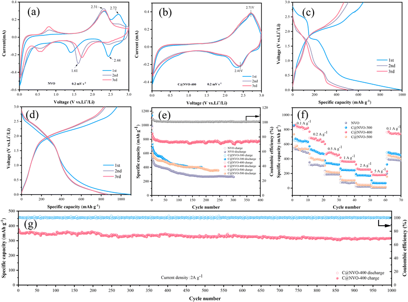
To evaluate the electrochemical performance of the NVO and C@NVO-400 electrodes, a coin-type cell was assembled with Li foil as the electrode and LiPF6 as the electrolyte. The first three CV curves of the NVO and C@NVO-400 electrodes at 0.2 mV s−1 are displayed in Fig. 4a and b. From the CV curve of NVO in Fig. 4a, it can be seen that the redox peak pair that appeared at 2.44/2.72 V in the first turn disappeared in the next test, which was related to the localized damage of the crystal structure during Li+ insertion/exfoliation,40 and the redox peak pair appearing at 0.57/0.81 V is due to the irreversible solid electrolyte interface (SEI) film on the electrodes,41,42 and the poor coincidence of the curves indicates the presence of many incomplete reversible reactions. The C@NVO-400 electrode in Fig. 4b shows redox peaks located at 2.41 V and 2.71 V. corresponding to the multi-step lithium insertion/extraction reaction.43,44 The curves coincide well with the second curve, indicating the remarkable reversibility of the C@NVO-400 electrode. Compared with the bare NVO electrode, the carbon layer on the surface of C@NVO-400 mitigates the occurrence of the side reactions and plays a role similar to that of the SEI membrane, and the buffer phase is able to mitigate the volumetric expansion effect during charge–discharge cycling, which is favorable to the improvement of its cycling performance.
Fig. 4c and d show the GCD curves of NVO and C@NVO-400 at a low current density of 0.1 A g−1. The plateaus during the charge/discharge process are consistent with the CV results, where both the discharge and plateau of C@NVO-400 are shifted to a higher voltage due to the formation of a carbon film, inhibiting the side reactions of NVO. Fig. 4e shows the cycling performance of the C@NVO-400 and NVO electrodes at 100 mA g−1. The C@NVO-400 electrode delivers an initial discharge-specific capacity of 1090.7 mA h g−1 with a good initial coulombic efficiency of 113.5%, which is higher than that of NVO (103.4%). This indicates that the presence of a carbon layer can improve the coulombic efficiency of electrode materials.45 After 400 cycles, C@NVO-400 exhibits a discharge-specific capacity of 779.1 mA h g−1 (the coulombic efficiency is 100.6%), which is higher than that of NVO (267.9 mA h g−1, 98.5%) after 400 cycles. This proves that the formation of a carbon film can boost the specific capacity of the MVO electrode and enhance the cycling stability. The initial decreasing capacity may be derived from the formation of a solid electrolyte film (SEI).46,47
The rate performance at various current rates ranging from 0.1 to 5 A g−1 is depicted in Fig. 4f, in which the C@NVO electrode delivers average specific capacities of 834.6, 674.2, 488.5, 373.7, 266.9 and 192.5 mA h g−1 at current rates of 0.1, 0.2, 0.5, 1.0, 2.0 and 5.0 A g−1, respectively, which are significantly higher than those of C@NVO-400. What is more, the average capacity can return to 772.7 mA h g−1 when the current rate decreases back to 0.1 A g−1, which is higher than that of the NVO electrode (394.1 mA h g−1), indicating highly reversible Li+ insertion/extraction in the C@NVO-400 electrode. The high capacity at high current density proves the rapid migration ability of Li+ in the composite material. Based on the rate data, the Ragone plot (Fig. S7†) of the electrodes is obtained. As described in Fig. S7,† C@NVO-400 delivers a maximum energy density of 829.1 W h kg−1 at a power density of 98.3 W kg−1, and a maximum power density of 1505 W kg−1 at an energy density of 30.1 W h kg−1, which are higher than those of the NVO electrode. The cell was further tested at 2 A g−1 to prove the long-term cycling stability of C@NVO-400 (Fig. 4g). As a result, C@NVO-400 displays a long cycle life up to 1000 cycles without obvious capacity decay with a CE of around 100%. The specific capacity and capacity retention of the C@NVO-400 electrode were 315.5 mA h g−1 and 90.5%, respectively. Furthermore, the cycling and rate performances of C@NVO-300 and C@NVO-500 electrodes were higher than those of the NVO electrodes.
The cycling and rate performances of C@NVO-X electrodes with different coating amounts were also improved (Fig. S8†). The good electrochemical performances of C@NVO electrodes were attributed to the fact that the carbon layer on the surface of the electrodes acted as an SEI-like membrane, which prevented the direct contact between NVO and the electrolyte, avoiding additional Li+ consumption and irreversible reactions in the subsequent cycles.48 Obviously, the amount and the thickness of the carbon film affects the properties of the composites.
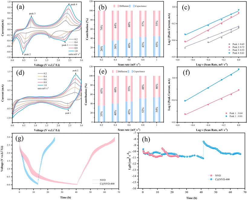
The electrochemical reaction kinetics of the C@NVO-400 electrode was evaluated using CV and galvanostatic intermittent titration technique (GITT) measurements. The Li+ storage behaviors of NVO (Fig. 5a) and C@NVO-400 (Fig. 5d) were evaluated by CV caused by polarization.49 The relationship between the peak current (i) and the scan rate (v) can be described using the following equation:50
| i = avb | (1) |
![[thin space (1/6-em)]](https://www.rsc.org/images/entities/char_2009.gif) (i) – log
(i) – log![[thin space (1/6-em)]](https://www.rsc.org/images/entities/char_2009.gif) (v) plots at peaks 1 and 2, the b values of C@NVO-400 were calculated to be 0.64 and 0.81, respectively, which are higher than those of NVO, namely 0.65, 0.72, 0.53 and 0.61, implying that C@/NVO-400 exhibits better pseudocapacitance behavior.51 As a result, the capacitive contribution ratios of C@NVO-400 (Fig. 5f) at 0.2, 0.4, 0.6, 0.8 and 1.0 mV s−1 were 35%, 40%, 45%, 52% and 54%, which are higher than those of NVO (Fig. 5c) at scanning rates of 26%, 36%, 40%, 43%, and 45%, respectively. It can be easily found that the contribution of pseudocapacitance is increasing with the increase of the scan rate and the contribution of diffusion capacitance is decreasing for both electrodes.52 This indicates that C@NVO-400 exhibits high-speed surface electrochemical reaction kinetics. To study the diffusion kinetics of Li+, the GITT technique was used and the results are shown in Fig. 5g and h. According to Fick's second law of diffusion, the DLi+ value of the electrodes can be calculated using the following equation:53
(v) plots at peaks 1 and 2, the b values of C@NVO-400 were calculated to be 0.64 and 0.81, respectively, which are higher than those of NVO, namely 0.65, 0.72, 0.53 and 0.61, implying that C@/NVO-400 exhibits better pseudocapacitance behavior.51 As a result, the capacitive contribution ratios of C@NVO-400 (Fig. 5f) at 0.2, 0.4, 0.6, 0.8 and 1.0 mV s−1 were 35%, 40%, 45%, 52% and 54%, which are higher than those of NVO (Fig. 5c) at scanning rates of 26%, 36%, 40%, 43%, and 45%, respectively. It can be easily found that the contribution of pseudocapacitance is increasing with the increase of the scan rate and the contribution of diffusion capacitance is decreasing for both electrodes.52 This indicates that C@NVO-400 exhibits high-speed surface electrochemical reaction kinetics. To study the diffusion kinetics of Li+, the GITT technique was used and the results are shown in Fig. 5g and h. According to Fick's second law of diffusion, the DLi+ value of the electrodes can be calculated using the following equation:53 | (2) |
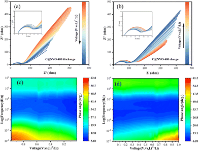
In order to further understand the interfacial behavior of the C@NVO-400 electrode, in situ EIS was performed in the frequency range of 0.01–100 kHz. Fig. 6a and b show the Nyquist curves of the C@NVO-400 electrodes at 1.0 V to 0.01 V and back to 1.0 V for one cycle. In general, the semicircle in the middle frequency region can be classified as a charge transfer resistance (Rct), and the slope of the straight line in the low frequency region represents Warburg impedance (Zw).55,56 During the discharge (lithium embedded) process where the electrode potential goes from 1.0 to 0.01 V, the Rct tends to decay, while Zw becomes smaller, indicating an increase in the diffusion resistance. The corresponding charging process shows a similar change, and the phenomenon suggests that the electrode has a small charge transfer resistance due to the formation of a strong SEI layer on its surface, which accelerates the electron transfer during cycling.57 The Bode plot expresses the phase angle (φ) as a function of frequency and is used to visualize the relative contributions of the capacitive and resistive elements, corresponding to the capacitive and diffusive contributions in the battery reaction, respectively, with an ideal capacitive contribution at φ = 90° and a diffusive contribution at φ = 0.58,59 The variation of φ with frequency proves a peak that closely matches the semicircle in the Nyquist plot (Fig. 6c and d). Furthermore, the EIS results of NVO and C@NVO-400 are presented in Fig. S9.† The electrolyte resistance (Rs) and charge transfer resistance (Rct) values of C@NVO-400 are 4.92 and 45.8 Ω, respectively, which are lower than those of NVO (Rs = 6.02 Ω and Rct = 152 Ω).
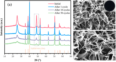
To investigate the effect of the carbon film on the stability of the electrochemical structure of the composite electrode, XRD and SEM tests were performed on the samples after 400 cycles (Fig. 7a–c). The XRD results show that the crystal structure of the C@NVO-400 electrode did not change significantly after 1, 10, and 50 cycles. As can be seen from the SEM results, the surface of the C@NVO-400 electrode is free of large cracks and holes, the nanowire structure remains relatively intact, and a relatively dense SEI layer is formed. The results indicate that the carbon film can effectively reduce or inhibit the volume expansion of NVO and maintain the structural integrity of the electrode.
4. Conclusions
Thus, well-dispersed CDs were prepared using the hydroxyl aldehyde condensation reaction, and then the structure of SEI-like membranes was constructed using CDs to reconstruct a carbon film on the surface of the NVO electrode. The pre-implemented interfacial engineering strategy makes the side reaction between the electrolyte and the active substance occur on the carbon film first, which forms a good protective layer structure for the NVO electrode. Furthermore, the carbon film solves the problems of poor electrical conductivity and dissolution of vanadates as electrode materials for LIBs, obtaining excellent structural integrity and cycling stability. The C@NVO-400 electrodes still maintained a discharge specific capacity of 315.5 mA h g−1 after 1000 cycles at a current density of 2 A g−1. The in situ electrochemical impedance spectra also indicate that the C@NVO-400 electrode exhibits a low charge transfer impedance, and the impedance keeps getting smaller and the charge transfer rate is increased during cycling. This strategy opens up new ideas for low-dimensional carbon materials to improve the long-term cycling performance and high-multiplication performance of vanadate electrodes.Author contributions
Zhengying Zhang: conceptualization, methodology, validation, and writing – original draft; Dong Fang: conceptualization, supervision, validation, and writing – reviewing and editing; Hua Yang: investigation and writing; Jian Liu: data curation and project administration; Feng Liu: review & editing; Anvar Khamidov: writing – review & editing; Olim Ruzimuradov: writing – reviewing and editing; and Jianhong Yi: supervision.Conflicts of interest
There are no conflicts to declare.Acknowledgements
This work was supported by the Science Research Project of Yunnan Province (No. 202302AH360001) and Yunnan Provincial Development and Reform Commission Support Project(2023-XMDJ-00617273).References
- Q. Liang, X. Yan, X. Liao, S. Cao, X. Zheng, H. Si, S. Lu and Y. Zhang, Nano Energy, 2015, 16, 329–338 CrossRef CAS.
- Q. Zhang, Q. Liang, Q. Liao, F. Yi, X. Zheng, M. Ma, F. Gao and Y. Zhang, Adv. Mater., 2017, 29, 1606703 CrossRef PubMed.
- M. Letellier, F. Chevallier, C. Clinard, E. Frackowiak, J.-N. Rouzaud, F. Béguin, M. Morcrette and J.-M. Tarascon, J. Chem. Phys., 2003, 118, 6038–6045 CrossRef CAS.
- Y. Lu, L. Yu, M. Wu, Y. Wang and X. W. Lou, Adv. Mater., 2018, 30, 1702875 CrossRef PubMed.
- J. Wang, J. Pei, K. Hua, D. Chen, Y. Jiao, Y. Hu and G. Chen, ChemElectroChem, 2018, 5, 737–742 CrossRef CAS.
- Q. Zhang, Q. Shi, H. Li, Z. Xiao, K.-P. Wang, L. Zong and L. Wang, J. Power Sources, 2019, 439, 227087 CrossRef CAS.
- C. F. Bie, J. Pei, G. Chen, Q. Zhang, J. X. Sun, Y. G. Yu and D. H. Chen, J. Mater. Chem. A, 2016, 4, 17063–17072 RSC.
- Y. Lu, J. Nai and X. W. Lou, Angew. Chem., Int. Ed., 2018, 57, 2899–2903 CrossRef CAS PubMed.
- B. Huang, W. Wang, T. Pu, J. Li, C. Zhao, L. Xie and L. Chen, Chem. Eng. J., 2019, 375, 121969 CrossRef CAS.
- R. Baddour-Hadjean, S. Bach, N. Emery and J. P. Pereira-Ramos, J. Mater. Chem., 2011, 21, 11296–11305 RSC.
- J. Lu, D. Zhang, Y. Wang and S. Ni, New J. Chem., 2021, 45, 11506–11511 RSC.
- Y. Cao, L. Xiao, M. L. Sushko, W. Wang, B. Schwenzer, J. Xiao, Z. Nie, L. V. Saraf, Z. Yang and J. Liu, Nano Lett., 2012, 12, 3783–3787 CrossRef CAS PubMed.
- D. Li, H. Chen, G. Liu, M. Wei, L.-X. Ding, S. Wang and H. Wang, Carbon, 2015, 94, 888–894 CrossRef CAS.
- Y. Liu, F. Fan, J. Wang, Y. Liu, H. Chen, K. L. Jungjohann, Y. Xu, Y. Zhu, D. Bigio, T. Zhu and C. Wang, Nano Lett., 2014, 14, 3445–3452 CrossRef CAS PubMed.
- J. Ding, H. Wang, Z. Li, A. Kohandehghan, K. Cui, Z. Xu, B. Zahiri, X. Tan, E. M. Lotfabad, B. C. Olsen and D. Mitlin, ACS Nano, 2013, 7, 11004–11015 CrossRef CAS PubMed.
- Y. Yan, Y.-X. Yin, Y.-G. Guo and L.-J. Wan, Adv. Energy Mater., 2014, 4, 1301584 CrossRef.
- S. Komaba, W. Murata, T. Ishikawa, N. Yabuuchi, T. Ozeki, T. Nakayama, A. Ogata, K. Gotoh and K. Fujiwara, Adv. Funct. Mater., 2011, 21, 3859–3867 CrossRef CAS.
- J. Xu, M. Wang, N. P. Wickramaratne, M. Jaroniec, S. Dou and L. Dai, Adv. Mater., 2015, 27, 2042–2048 CrossRef CAS PubMed.
- L. Qie, W. Chen, X. Xiong, C. Hu, F. Zou, P. Hu and Y. Huang, Adv. Sci., 2015, 2, 12 Search PubMed.
- B. C. M. Martindale, G. A. M. Hutton, C. A. Caputo and E. Reisner, J. Am. Chem. Soc., 2015, 137, 6018–6025 CrossRef CAS PubMed.
- X. Yin, H. Chen, C. Zhi, W. Sun, L.-P. Lv and Y. Wang, Small, 2018, 14, 1800589 CrossRef PubMed.
- F. Khan, M. Oh and J. H. Kim, Chem. Eng. J., 2019, 369, 1024–1033 CrossRef CAS.
- W. Liu, M. Li, G. Jiang, G. Li, J. Zhu, M. Xiao, Y. Zhu, R. Gao, A. Yu, M. Feng and Z. Chen, Adv. Energy Mater., 2020, 10, 2001275 CrossRef CAS.
- Y. H. Cao, J. Y. Wang, X. T. Chen, B. Shi, T. Chen, D. Fang and Z. P. Luo, Mater. Lett., 2019, 237, 122–125 CrossRef CAS.
- D. Pan, J. Zhang, Z. Li and M. Wu, Adv. Mater., 2010, 22, 734–738 CrossRef CAS PubMed.
- R. Guo, C. Lv, W. Xu, J. Sun, Y. Zhu, X. Yang, J. Li, J. Sun, L. Zhang and D. Yang, Adv. Energy Mater., 2020, 10, 1903652 CrossRef CAS.
- S. Qiu, L. Xiao, M. L. Sushko, K. S. Han, Y. Shao, M. Yan, X. Liang, L. Mai, J. Feng, Y. Cao, X. Ai, H. Yang and J. Liu, Adv. Energy Mater., 2017, 7, 1700403 CrossRef.
- Q. Ouyang, G. Li, X. Zhang, X. Zhao, Y. Wang, Q. Wang, Z. Fan, J. Wang and L. Li, Chem. Eng. J., 2023, 460, 141762 CrossRef CAS.
- S. Huang, J. P. Tu, X. M. Jian, Y. Lu, S. J. Shi, X. Y. Zhao, T. Q. Wang, X. L. Wang and C. D. Gu, J. Power Sources, 2014, 245, 698–705 CrossRef CAS.
- Z. Y. Liang, Y. M. Zhao, L. Z. Ouyang, Y. Z. Dong, Q. Kuang, X. H. Lin, X. D. Liu and L. Yan, J. Power Sources, 2014, 252, 244–247 CrossRef CAS.
- B. Li, Y. Si, B.-X. Zhou, Q. Fang, Y.-Y. Li, W.-Q. Huang, W. Hu, A. Pan, X. Fan and G.-F. Huang, ACS Appl. Mater. Interfaces, 2019, 11, 17341–17349 CrossRef CAS PubMed.
- A. Ranganathan, V. R. Pedireddi and C. N. R. Rao, J. Am. Chem. Soc., 1999, 121, 1752–1753 CrossRef CAS.
- C. T. Seto and G. M. Whitesides, J. Am. Chem. Soc., 1993, 115, 905–916 CrossRef CAS.
- F. Wang, Q. Wang, S. Wang, K. Zhang, S. Jia, J. Chen and X. Wang, ACS Nano, 2022, 16, 9049–9061 CrossRef CAS PubMed.
- D. Fang, X. Xu, R. Bao, R. Wan, F. Yang, J. Yi, T. Zeng and O. Ruzimuradov, J. Environ. Chem. Eng., 2021, 9, 104765 CrossRef CAS.
- Y. Yu, C. Niu, C. Han, K. Zhao, J. Meng, X. Xu, P. Zhang, L. Wang, Y. Wu and L. Mai, Ind. Eng. Chem. Res., 2016, 55, 2992–2999 CrossRef CAS.
- H. Ma, S. Zhang, W. Ji, Z. Tao and J. Chen, J. Am. Chem. Soc., 2008, 130, 5361–5367 CrossRef CAS PubMed.
- Y. Sun, X. Hu, W. Luo and Y. Huang, J. Phys. Chem. C, 2012, 116, 20794–20799 CrossRef CAS.
- M. Du, Z. Miao, H. Li, F. Zhang, Y. Sang, L. Wei, H. Liu and S. Wang, Nano Energy, 2021, 89, 106477 CrossRef CAS.
- G. J. Yang, M. M. Cui, T. Han, D. Fang, X. J. Lu, S. Peng, O. Ruzimuradov and J. H. Yi, J. Electrochem. Soc., 2021, 168, 110546 CrossRef CAS.
- S. Shao, B. Liu, M. Zhang, J. Yin, Y. Gao, K. Ye, J. Yan, G. Wang, K. Zhu and D. Cao, J. Energy Storage, 2021, 35, 102254 CrossRef.
- D. Narsimulu, A. K. Kakarla and J. Su Yu, J. Energy Chem., 2021, 58, 25–32 CrossRef CAS.
- J. B. Lee, J. Moon, O. B. Chae, J. G. Lee, J. H. Ryu, M. Cho, K. Cho and S. M. Oh, Chem. Mater., 2016, 28, 5314–5320 CrossRef CAS.
- S. Shao, B. Liu, M. Zhang, J. Yin, Y. Gao, K. Ye, J. Yan, G. Wang, K. Zhu and D. Cao, J. Energy Storage, 2021, 35, 102254 CrossRef.
- Z. Tang, S. Zhou, Y. Huang, H. Wang, R. Zhang, Q. Wang, D. Sun, Y. Tang and H. Wang, Electrochem. Energy Rev., 2023, 6, 8 CrossRef CAS.
- H. J. Huang, X. Xia, J. W. Yun, C. Huang, D. L. Li, B. B. Chen, Z. H. Yang and W. X. Zhang, Energy Storage Mater., 2022, 52, 473–484 CrossRef.
- Y. Song, Y. F. Geng, Z. Y. Peng, Q. J. Zhu, S. P. Liang, Y. H. Li, J. Zhu, Y. G. Liu, L. Dai, Z. X. He and L. Wang, Ceram. Int., 2022, 48, 24706–24715 CrossRef CAS.
- S. Chen, R. Tao, J. Tu, P. Guo, G. Yang, W. Wang, J. Liang and S.-Y. Lu, Adv. Funct. Mater., 2021, 31, 2101199 CrossRef CAS.
- Y. Xu, G. L. Fan, P. X. Sun, Y. Guo, Y. Y. Wang, X. J. Gu, L. M. Wu and L. Yu, Angew. Chem., Int. Ed., 2023, 62, 26 Search PubMed.
- M. Y. Bao, Z. C. Y. Zhang, X. G. An, J. Liu, J. K. Feng, B. J. Xi and S. L. Xiong, Nano Res., 2023, 16, 2445–2453 CrossRef CAS.
- N. N. Liu, X. Wu, L. S. Fan, S. Gong, Z. K. Guo, A. S. Chen, C. Y. Zhao, Y. C. Mao, N. Q. Zhang and K. N. Sun, Adv. Mater., 2020, 32, 42 Search PubMed.
- D. Zhao, C. Wang, Y. Ding, M. Ding, Y. Cao and Z. Chen, ChemSusChem, 2022, 15, e202200479 CrossRef CAS PubMed.
- Z. Yan, Z. Sun, L. Zhao, H. Liu, Z. Guo, Y. Qiu, P. Wang and L. Qian, Mater. Today Nano, 2022, 20, 20 Search PubMed.
- N. Zhang, K. Liu, H. B. Zhang, X. F. Wang, Y. H. Zhou, W. X. He, J. L. Cui and J. C. Sun, Small, 2023, 19, 1 Search PubMed.
- B. X. Hou, X. M. Cui, Q. Zhang and Y. G. Chen, J. Cent. South Univ., 2019, 26, 1435–1442 CrossRef CAS.
- P. Xue, L. Zhang, L. Y. Zhang, X. M. Feng, Y. B. Zhang, W. W. Hao, H. B. Wang and H. H. Zheng, Electrochim. Acta, 2014, 136, 330–339 CrossRef CAS.
- C. Yuan, M. Wang, J. Wang, W. Chen, N. Li, Y. Fan, Z. Ma, W. Guo and L. Mai, Adv. Energy Mater., 2023, 13, 2302015 CrossRef CAS.
- S. Touzain, Electrochim. Acta, 2010, 55, 6190–6194 CrossRef CAS.
- J. S. Ko, C.-H. Lai, J. W. Long, D. R. Rolison, B. Dunn and J. Nelson Weker, ACS Appl. Mater. Interfaces, 2020, 12, 14071–14078 CrossRef CAS PubMed.
Footnote |
| † Electronic supplementary information (ESI) available. See DOI: https://doi.org/10.1039/d4dt01162g |
| This journal is © The Royal Society of Chemistry 2024 |

