Purification of poly(acrylic acid) using a membrane ultra-filtration unit in flow
Laurens
Brocken
a,
Paul D.
Price
b,
Jane
Whittaker
b and
Ian R.
Baxendale
 *a
*a
aDepartment of Chemistry, University of Durham, South Road, Durham, DH1 3LE, UK. E-mail: i.r.baxendale@durham.ac.uk; Fax: +44 (0)191 334 2051; Tel: +44 (0)191 334 2185
bUnilever R&D Port Sunlight, Quarry Road East, Bebington, Wirral, CH63 3JW, UK
First published on 10th July 2017
Abstract
We have developed methodology to synthesise aqueous soluble polymers such as poly(acrylic acid) in flow, enabling access to a variety of molecular weights [L. Brocken, P. D. Price, J. Whittaker and I. R. Baxendale, React. Chem. Eng., 2017, in press]. However, full conversion was hard to achieve without increasing the dispersity and therefore purification was necessary. In this work we demonstrate that flow polymerisation can be directly coupled with purification to furnish a purified polymer sample in under one hour.
1 Introduction
Aqueous soluble polymers are important materials utilised in many commercial products, for example, being commonly encountered in detergents and other cleaning products. Significant research has therefore been invested towards the synthesis of water soluble polymers using a variety of polymerisation techniques including the use of flow chemistry as an advantageous processing tool.1 A principal advantage of flow polymerisation is the ability to rapidly screen various parameters for the fast optimisation of the polymers synthesis. Indeed, several papers have described the possibility to follow a reaction in-line or on-line,2–4 and thus analyse real time data to optimise the process.5 In an ideal laboratory scenario the reaction conditions would be screened and used to prepare the polymer at a preparative scale, this would be followed by its direct purification and linked to analysis either in-line or on-line. Unfortunately, purification is often a very time consuming step, this therefore creates a fundamental disconnect in the ability to perform flow synthesis of new test polymers.We therefore wished to investigate this current limitation in polymer purification directed at bridging flow synthesis and polymer analysis. To this end several polymer purification techniques are available depending on a combination of factors such as the polymerisation technique used, the chemical structure of the polymer and on the relevant application of the final polymer. For some applications a high purity, narrow dispersity, polymer is required, for example in certain medicinal applications6–9 or in organic photovoltaic devices;10 however other applications such as thickeners or surfactants do not necessarily require polymers with such precise dispersity. As we had previously been investigating water soluble polymers for bulk application in household products we decided to concentrate upon this area.11
Dialysis is a proven method for the efficient purification of a broad range of macromolecules such as enzymes,12,13 proteins,13 polysaccharides,14 lignin sulfonates,15 and polymers.16–19 The concept of dialysis is the diffusion of material across a gradient from a high concentration to a lower concentration across a porous membrane.20,21 Several variations of dialysis exist, such as counterflow and microdialysis systems.22 As a further extension of dialysis, ultra-filtration can be used23 and again several variations are available, for example centrifugal,24,25 and tangential/crossflow ultra-filtration.26 The added advantages of ultra-filtration are that it is less time consuming and allows for the direct concentration of samples. Furthermore, different molecular weights can be sequentially separated as membranes with various molecular weight cut off (MWCO) are commercially available. However, one drawback of these systems is their limited compatibility with commonly encountered solvents, albeit not an issue for our application.†
Therefore based upon an ultra-filtration system we set out to establish a unified synthesis and purification platform for generating water soluble poly(acrylic acid). Our aim was to develop a system which could deliver a new purified sample; 100–200 mg dry weight – sufficient for fully analytical assessment, in under 1 h, an hour was targeted as this matched the run times for GPC analyses.
As part of our study several parameters relating to the time needed for purification were envisaged: the ultra-filtration set-up (path length and configuration of multiple membranes), monomer conversion, reaction time and concentration. The monomer conversion will directly influence the time it takes to purify the sample. A sample with a high residual monomer content will inevitably require a longer time to purify compared to one with low residual content. Additionally, the concentration was also expected to influence the time required to cycle the sample through the membrane system, with larger volumes requiring longer times.
2 Experimental
2.1 Materials
Acrylic acid (Alfa Aesar, 99%), 2,2′-azobis(2-methylpropionamidine) dihydrochloride (Sigma Aldrich, 97%) and sodium selenite (Alfa Aesar, 98%) were used without further purification. The flow polymerisation was carried out on a FlowSyn, a reactor system available from Uniqsis Ltd. The purification was performed using Vivaflow 200 hydrosart membranes with a MWCO of 2000 Da, and a peristaltic pump with adjustable flow rate both available from Sartorius Stedim Biotech.‡ Each membrane has a surface of 200 cm2 and is fabricated from stabilised cellulose.2.2 Polymerisation and purification
The polymer samples used for purification were synthesised in accordance with a previously described protocol.11 The reaction conditions used and the corresponding residual monomer concentrations are shown in Table 1. The synthesis and purification of the various polymeric samples was performed in a combined system. The membranes were positioned in series, parallel or a combination of these two configurations (Fig. 2) and the flow rate was adjusted to the design. The volume of the polymer reservoir was maintained constant by the addition of water by an auxiliary pump adjusted to deliver at the same rate as the extraction.| Residual acrylic acid (%) | [Acrylic acid] (mM) | [Initiator] (mol%) | Residence time (min) |
|---|---|---|---|
| 20 | 0.7 | 2.50 | 10 |
| 30 | 0.7 | 1.25 | 10 |
| 70 | 0.7 | 1.25 | 5 |
2.3 Characterisation
1H NMR spectra were recorded using water suppression on a Bruker-Avance 400 instrument using D2O as the solvent. The technique used was based on the Watergate27 suppression technique.28,293 Results and discussion
3.1 Translation of batch to flow
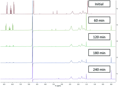
Initially batch dialysis was performed to obtain a reference point for the ultra-filtration purification. Four samples of 25 mL with 30 mol% (0.2 mM) residual monomer were loaded into twenty centimetres long and four centimetre wide dialysis tubing. These samples were then placed into individual buckets filled with 4 L of water and stirred for the allotted lengths of time (60–240 min) before being removed and analysed by NMR. The MWCO of the dialysis tubing used in the batch purification was specified as 3000 Da this was higher than the ultra-filtration membranes used (2000 Da) in the subsequent work but allowed initial benchmarking regarding timings and for the NMR analysis protocols to be validated. The amount of residual acrylic acid (1H NMR between 6.3 ppm and 5.8 ppm) decreased over time (Fig. 1) where the amount of poly(acrylic acid) (between 2.5 ppm and 1.6 ppm) remained constant. In addition the filtrate was tested and did not contain any polymeric material. The two singlets more prevalent in the upper two spectra situated around 3.5 ppm represent the internal standard namely, dimethoxyethane used to calibrate the amount of residual acrylic acid at t = 0. As the molecular weight of dimethoxyethane is 90.12 g mol−1 this was also separated from the polymer. Using this set-up full purification was not achieved even after four hours (Fig. 1), with a very small quantity (1%) of acrylic acid still present. This indicates the purification takes over four hours.3.2 Reactor design and configuration
To operate the ultra-filtration system in an optimal way it is paramount that the pressure of the membrane is maintained at a constant 3 bar. Lower pressure results in an increase in the purification time as less solution and accompanying monomer is passed through the membrane. Too high a pressure results in degradation of the membrane. To achieve a pressure of 3 bar the system has to operate with a flow rate of around 40 mL min−1 for membranes in series or a combination of series/parallel (Fig. 2A and B). For operation with two or three membranes working in parallel a flow of 80 or 120 mL min−1 respectively is required (Fig. 2C).The influence of the layout of the membranes on the purification performance was studied (Fig. 3).
 | ||
| Fig. 3 Influence of reactor design on separation, the determination of residual monomer was performed by 1H NMR analysis. | ||
3.3 Residual acrylic acid removal
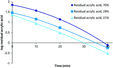
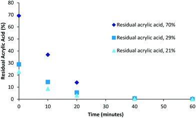
Although polymerisation processes can often be driven to completion (consumption of all monomer) through either the use of prolonged reaction times or the addition of extra initiator this often has an impact on the characteristics of the polymers produced (increased branching, cross-linking, molecular weight and dispersity). Under scenarios where reaction conditions are specifically selected to generate bespoke polymers possessing particular molecular weight or dispersity ranges the resulting product mixture could retain drastically different amounts of unconsumed monomer. Therefore we decided to investigate the impact of varying levels of residual acrylic acid within samples on the required purification times. To this end samples representing high (70%, 0.49 mM), medium (29%, 0.2 mM) and low (21%, 0.15 mM) residual acrylic acid were generated (Fig. 4). Over the first twenty minutes the relative difference between the different compositions tends towards an equitable level and that in each case full purification was achieved within the range of 40–60 minutes. When the same data is plotted as a log function (Fig. 5) it becomes clear that the purification rate is similar for all concentrations if the sample volume is fixed. | ||
| Fig. 5 Log function of influence of residual acrylic acid of residual acrylic acid, 50 mL sample was used. | ||
3.4 Volume of processed sample
During a typical screening process several different concentrations and sample volumes were evaluated. As well as affecting the polymerisation reaction this will also have an impact on the downstream purification time. To determine the influence of sample concentration and volume on purification, a 0.7 mM solution of poly(acrylic acid) containing 0.2 nM acrylic acid was diluted with deionized water to prepare a series of known concentrations (Table 2). In each case the volume was correspondingly increased so that each test sample contain an equivalent amount of residual acrylic acid.| Concentration acrylic acid (mM) | Dilution factor | Total volume (mL) |
|---|---|---|
| 0.2 | 1 | 50 |
| 0.1 | 2 | 100 |
| 0.05 | 4 | 200 |
| 0.033 | 6 | 300 |
| 0.0025 | 8 | 400 |
In cases where a large volume and therefore a low concentration were generated this invariably extended the purification time (Fig. 6). Larger sample volumes inherently necessitate longer cycle times due to the maximum flow rates (pressure determined) and fixed internal volume of the extractor unit. The data shows that in general a smaller volume (within the limits of the extractor volume) and higher concentration gives a more efficient purification. However, there are limits imposed by the maximum viscosity of the sample that can be processed as very high viscosity material leads to degradation of the membranes. A strategic balance must therefore be reached addressing the extractor limits (maximum viscosity, system pressure and surface area) against a desire for rapid purification (flow rate) and sufficient processed polymer to enable full analysis and testing (volumetric sample size and concentration). In addition, as our ultimate goal was to couple the purification stage directly to a previously performed flow polymer synthesis and thereby create a unified flow solution we elected to explore a concentration range based upon a flow polymer reactor output. In our previous polymer synthesis work an effective monomer concentration range of 0.4–1 mM had been established for the synthesis of poly(acrylic acid).11 To attain a sufficient processing volume and an adequate amount of isolated material a dilution factor of 5![[thin space (1/6-em)]](https://www.rsc.org/images/entities/char_2009.gif) :
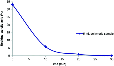
:![[thin space (1/6-em)]](https://www.rsc.org/images/entities/char_2009.gif) 1 based upon 5–10 mL of the polymer synthesis stream offered a good compromise. In an example purification procedure a diluted 25 mL sample volume which contained 33% residual acrylic acid (1.2 mmol; 48 mM) was processed. The purification was shown to be complete within 30 minutes (Fig. 7) and gave 120 mg of dry poly(acrylic acid) which was sufficient for all analysis (solid state and liquid NMR, GPC, etc.). With the successful realisation of this flow purification we next linked the unit directly to a previously devised polymerisation reactor11 to create a combined system (Fig. 8). In this two stage process the monomer and initiator are first merged at a T-piece before entering a heated 52 mL FEP (fluorinated ethylene propylene copolymer) coil reactor where the polymerisation takes place. The exiting solution was then directed by a switching valve to either a bulk collection vessel (containing sodium selenite to terminate the polymerisation) or to a feed tank at the front end of the purification unit (normally an aliquot of 5–10 mL). An auxiliary make-up pump was used to deliver water to the feed tank during the purification process maintaining a constant volume. The stock solution from the feed tank was pumped at 40 mL min−1 to the membrane series maintaining a 3–4 bar pressure gradient. The extruded filtrate is collected to a receiving vessel enabling if so required the re-isolation of the removed monomer. The principle flow line carrying the purifying polymer exits the membrane zone and is diverted to return to the stock feed tank in a recycling mode operation. Sampling of the feed tank and analysis by 1H NMR allows determination of the residual acrylic acid contamination. Once the solution is deemed purified (∼30 min) a switching valve is used to direct the purified solution to a final collection vessel for full analysis and isolation (this also initiates a reduced feed from the water make-up pump). Using this approach a small volume of the full flow polymerisation stream can be rapidly purified for full analysis whereas the bulk sample is retained for subsequent processing if of interest. Although not integrated into this specific design a simple modification incorporating a liquid handler could be used to exchange the collection and feed vessels (including monomer inputs) allowing a fully automated process.
1 based upon 5–10 mL of the polymer synthesis stream offered a good compromise. In an example purification procedure a diluted 25 mL sample volume which contained 33% residual acrylic acid (1.2 mmol; 48 mM) was processed. The purification was shown to be complete within 30 minutes (Fig. 7) and gave 120 mg of dry poly(acrylic acid) which was sufficient for all analysis (solid state and liquid NMR, GPC, etc.). With the successful realisation of this flow purification we next linked the unit directly to a previously devised polymerisation reactor11 to create a combined system (Fig. 8). In this two stage process the monomer and initiator are first merged at a T-piece before entering a heated 52 mL FEP (fluorinated ethylene propylene copolymer) coil reactor where the polymerisation takes place. The exiting solution was then directed by a switching valve to either a bulk collection vessel (containing sodium selenite to terminate the polymerisation) or to a feed tank at the front end of the purification unit (normally an aliquot of 5–10 mL). An auxiliary make-up pump was used to deliver water to the feed tank during the purification process maintaining a constant volume. The stock solution from the feed tank was pumped at 40 mL min−1 to the membrane series maintaining a 3–4 bar pressure gradient. The extruded filtrate is collected to a receiving vessel enabling if so required the re-isolation of the removed monomer. The principle flow line carrying the purifying polymer exits the membrane zone and is diverted to return to the stock feed tank in a recycling mode operation. Sampling of the feed tank and analysis by 1H NMR allows determination of the residual acrylic acid contamination. Once the solution is deemed purified (∼30 min) a switching valve is used to direct the purified solution to a final collection vessel for full analysis and isolation (this also initiates a reduced feed from the water make-up pump). Using this approach a small volume of the full flow polymerisation stream can be rapidly purified for full analysis whereas the bulk sample is retained for subsequent processing if of interest. Although not integrated into this specific design a simple modification incorporating a liquid handler could be used to exchange the collection and feed vessels (including monomer inputs) allowing a fully automated process.
 | ||
| Fig. 6 Extraction rates for different concentration and volumes (Table 2) of residual acrylic acid performed using three membranes in series as shown in Fig. 2A. | ||
Using the described system a series of poly(acrylic acid) compositions (20–70% residual monomer, Table 1; molecular weight range 158![[thin space (1/6-em)]](https://www.rsc.org/images/entities/char_2009.gif) 000–378
000–378![[thin space (1/6-em)]](https://www.rsc.org/images/entities/char_2009.gif) 000 Da) were successfully synthesised and an aliquot purified. In all cases the secondary purification time of 30 minutes was sufficient. Therefore, with the capability to purify a sample within 30 minutes and an initial synthesis time of 5–20 minutes, a new purified polymer sample can be generated approximately every hour (note including changeover time). This means 8–10 samples can be easily synthesised and purified (excluding drying of the sample) during a standard working day.
000 Da) were successfully synthesised and an aliquot purified. In all cases the secondary purification time of 30 minutes was sufficient. Therefore, with the capability to purify a sample within 30 minutes and an initial synthesis time of 5–20 minutes, a new purified polymer sample can be generated approximately every hour (note including changeover time). This means 8–10 samples can be easily synthesised and purified (excluding drying of the sample) during a standard working day.
As a final proof of principle we wished to test the amenability of this approach to another aqueous soluble polymer namely, poly(vinylpyrrolidone). In this case a crude sample was prepared in flow which initially contained 21% residual vinylpyrrolidone (0.15 mM). A 5 mL sample cut from the flow stream was directed into the membrane separator, diluted and then successfully purified in less than 40 minutes. As demonstrated it should in theory be possible to purify several other polymers using the same approach, although certain limitations regarding the membranes compatible with potential solvents and additives would need to be taken into consideration.
4 Conclusions
In conclusion, we have demonstrated that a simple and practical flow system can be constructed from commercially available parts to rapidly unify the synthesis and purification stages of water soluble polymer preparation. The configuration of the downstream membrane separation unit was optimised allowing the entire process of synthesis and then purification to be conducted within one hour. By operating the unit in an iterative sequential mode, multiple samples can be processed using the same device over the course of a working day. This unit is ideally suited to research endeavours facilitating reaction optimisation and material property screening of new polymeric materials by yielding a purified sample suitable for full spectral and analytical analysis.Acknowledgements
We are grateful for financial support by Unilever and EPSRC (RG64908 to LB) and the Royal Society (UF130576 to IRB). For initial investigations into the purification of polymers we would like to thank Niamh C. Thomas and the Nuffield foundation for sponsorship to enable her involvement.References
- B. L. Rivas, E. D. Pereira and I. Moreno-Villoslada, Prog. Polym. Sci., 2003, 28, 173–208 CrossRef CAS.
- J. P. McMullen and K. F. Jensen, Annu. Rev. Anal. Chem., 2010, 3, 19–42 CrossRef CAS PubMed.
- C. H. Hornung, K. von Känel, I. Martinez-Botella, M. Espiritu, X. Nguyen, A. Postma, S. Saubern, J. Chiefari and S. H. Thang, Macromolecules, 2014, 47, 8203–8213 CrossRef CAS.
- M. Stephan, S. Grosse, M. Stintz and U. Blankschein, J. Appl. Polym. Sci., 2007, 103, 258–262 CrossRef CAS.
- F. Bally, C. A. Serra, C. Brochon, N. Anton, T. Vandamme and G. Hadziioannou, Macromol. React. Eng., 2011, 5, 542–547 CrossRef CAS.
- K. Modjarrad, in Handbook of Polymer Applications in Medicine and Medical Devices, ed. K. Modjarrad and S. Ebnesajjad, William Andrew Publishing, Oxford, 2014, pp. 1–7 Search PubMed.
- L. Czuba, in Handbook of Polymer Applications in Medicine and Medical Devices, ed. K. Modjarrad and S. Ebnesajjad, William Andrew Publishing, Oxford, 2014, pp. 9–19 Search PubMed.
- W. He and R. Benson, in Handbook of Polymer Applications in Medicine and Medical Devices, ed. K. Modjarrad and S. Ebnesajjad, William Andrew Publishing, Oxford, 2014, pp. 55–76 Search PubMed.
- Z. Zhang, O. Ortiz, R. Goyal and J. Kohn, in Handbook of Polymer Applications in Medicine and Medical Devices, ed. K. Modjarrad and S. Ebnesajjad, William Andrew Publishing, Oxford, 2014, pp. 303–335 Search PubMed.
- R. S. Ashraf, B. C. Schroeder, H. A. Bronstein, Z. Huang, S. Thomas, R. J. Kline, C. J. Brabec, P. Rannou, T. D. Anthopoulos, J. R. Durrant and I. McCulloch, Adv. Mater., 2013, 25, 2029–2034 CrossRef CAS PubMed.
- L. Brocken, P. D. Price, J. Whittaker and I. R. Baxendale, React. Chem. Eng., 2017 Search PubMed , in press.
- M. S. Nightingale, S.-C. Tsai and J. L. Gaylor, J. Biol. Chem., 1967, 242, 341–349 CAS.
- M. Mulder, in Membranes in Bioprocessing: Theory and Applications, ed. J. A. Howell, V. Sanchez and R. W. Field, Springer Netherlands, Dordrecht, 1993, pp. 13–54 Search PubMed.
- T. R. Cipriani, C. G. Mellinger, L. M. de Souza, C. H. Baggio, C. S. Freitas, M. C. A. Marques, P. A. J. Gorin, G. L. Sassaki and M. Iacomini, J. Nat. Prod., 2006, 69, 1018–1021 CrossRef CAS PubMed.
- Q. P. Peniston and J. L. McCarthy, J. Am. Chem. Soc., 1948, 70, 1324–1328 CrossRef CAS PubMed.
- R. Ghidoni, S. Sonnino and G. Tettamanti, Lipids, 1978, 13, 820–822 CrossRef CAS PubMed.
- N. A. O. Pitombeira, J. G. V. Neto, D. A. Silva, J. P. A. Feitosa, H. C. B. Paula and R. C. M. de Paula, Carbohydr. Polym., 2015, 117, 610–615 CrossRef CAS PubMed.
- J. Bustamante, P. Navarro, G. Arana, A. de Diego and J. M. Madariaga, Talanta, 2013, 114, 32–37 CrossRef CAS PubMed.
- M. L. Fishman and F. R. Eirich, J. Phys. Chem., 1971, 75, 3135–3140 CrossRef CAS.
- C. H. H. Neufeld and C. S. Marvel, J. Polym. Sci., Part A: Polym. Chem., 1966, 4, 2907–2908 CrossRef CAS.
- B. Kwon, H. K. Shon and J. Cho, Sep. Sci. Technol., 2009, 44, 3224–3238 CrossRef CAS.
- S. Song, A. K. Singh, T. J. Shepodd and B. J. Kirby, Anal. Chem., 2004, 76, 2367–2373 CrossRef CAS PubMed.
- S. Qin, D. Qin, W. T. Ford, J. E. Herrera, D. E. Resasco, S. M. Bachilo and R. B. Weisman, Macromolecules, 2004, 37, 3965–3967 CrossRef CAS.
- R. Brinkman and J. V. Steinfoorn, Biochem. J., 1936, 30, 1523–1525 CrossRef CAS PubMed.
- N. García-Otero, J. Alonso-Lorenzo, M. del Carmen Barciela-Alonso, P. Bermejo-Barrera and A. Moreda-Pineiro, Microchem. J., 2015, 122, 50–56 CrossRef.
- C.-W. Cho, D.-Y. Lee and C.-W. Kim, Carbohydr. Polym., 2003, 54, 21–26 CrossRef CAS.
- M. Liu, X. An Mao, C. Ye, H. Huang, J. K. Nicholson and J. C. Lindon, J. Magn. Reson., 1998, 132, 125–129 CrossRef CAS.
- R. W. Adams, C. M. Holroyd, J. A. Aguilar, M. Nilsson and G. A. Morris, Chem. Commun., 2013, 49, 358–360 RSC.
- J. A. Aguilar and S. J. Kenwright, Analyst, 2016, 141, 236–242 RSC.
Footnotes |
| † The Vivaflow 200 by Sartorius Stedim Biotech is only compatible with the following solvents: water, ethanol (70% w/w), methanol (60% w/w), n-butanol (70% w/w), formaldehyde (30% w/w) and formic acid (5% w/w). |
| ‡ A membrane with the smallest possible pore size (MWCO of 2000 Da) permits purification of the polymer by exclusion of the monomer and oligomers only. |
| This journal is © The Royal Society of Chemistry 2017 |


