A high energy-density tin anode for rechargeable magnesium-ion batteries†
Nikhilendra
Singh
*,
Timothy S.
Arthur
,
Chen
Ling
,
Masaki
Matsui
and
Fuminori
Mizuno
Toyota Research Institute of North America, 1555 Woodridge Avenue, Ann Arbor, MI 48105, USA. E-mail: nikhilendra.singh@tema.toyota.com; Fax: +1-734-995-2549; Tel: +1-734-995-5861
First published on 8th November 2012
Abstract
A high energy-density Sn anode capable of displaying superior operating voltages and capacity, for rechargeable Mg-ion batteries, is highlighted. The intended application and performance of the anode is confirmed by coupling it with a Mo6S8 cathode in a conventional battery electrolyte.
Over the last few decades, the automobile industry has begun focusing on alternative technologies to traditional combustion engines, which currently utilize carbon based fossil fuels. The introduction of electric vehicles (EVs) and plug-in hybrid vehicles (PHVs) via the use of such alternative technologies (e.g. batteries) as stand-alone or tandem energy sources is slowly revolutionizing the face of the automobile industry. However, while batteries are a cleaner alternative to fossil fuels, concerns over their long range performance in automobiles have hampered their widespread use.1 Hence, high performance battery systems which meet automobile energy use, and especially space requirements, remain paramount in establishing the next generation of EVs and PHVs.2,3
In this regard, multivalent battery systems like rechargeable magnesium (Mg), calcium and aluminum-ion batteries are garnering more interest as candidate post-lithium (Li) systems.4–6 Mg, being divalent and denser, is theoretically capable of delivering a higher volumetric energy-density (3833 mA h cm−3) than Li (2061 mA h cm−3).1–3 Reports on the advantages of such high energy-density Mg batteries, and interest in the field of new cathodes and electrolytes for Mg batteries have steadily increased.7–11
To be competitive with current Li-ion systems in terms of energy-density, high voltage and high capacity Mg systems must be developed. To date, various organohaloaluminates [(MgR2)x–(AlCl3−nRn)y] have been utilized as alternative electrolytes for Mg systems, since conventional battery electrolytes (TFSI−, ClO4−, PF6−) form a Mg2+ blocking layer on the Mg metal anode surface.11–13 However, recent reports have shown that these organohaloaluminate electrolytes provide a limited operating voltage window when tested against typical battery current collectors.14 It is nonetheless possible to develop high voltage Mg systems via the use of conventional battery electrolytes, if the anode system is changed from a Mg metal anode to a Mg-ion insertion-type anode. This change would negate the challenge posed by the Mg2+ blocking layer on the Mg metal anode surface. The use of such insertion-type anodes has been abundant in Li-ion battery technology, where the use of a Li metal anode is deemed impractical, primarily due to dendrite formation.7,15–17
We have previously reported the use of bismuth (Bi) as a Mg2+ insertion-type anode material, and shown it to be compatible with conventional battery electrolytes.3 Since the ability to deliver high energy-density depends on cell voltage and capacity, it is essential that we develop next generation Mg-ion battery anode materials which remain compatible with high voltage conventional battery electrolytes, while displaying lower Mg2+ insertion/extraction voltages and higher capacities than Bi.1,3 This report presents a high energy-density tin (Sn) anode which is capable of displaying these necessary characteristics.
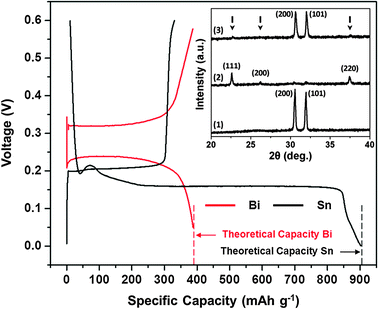
Fig. 1 shows the 1st cycle galvanostatic half-cell (anode/Mg) magnesiation/de-magnesiation curves for a Sn and a Bi anode at a 0.002 C rate. This experiment was executed in an organohaloaluminate electrolyte (see ESI,† i and iii) to test the feasibility of using an insertion-type Sn anode in Mg-ion batteries. The magnesiation (defined as insertion of Mg2+) plateau observed at +0.15 V corresponds to the formation of Mg2Sn according to binary phase diagrams, and reaction (1):18
| Sn + 2Mg2+ + 4e− → Mg2Sn | (1) |
The experimental result of the electrochemical voltage of formation of Mg2Sn concurs with theoretical DFT calculations. The de-magnesiation (defined as extraction of Mg2+) plateau is observed at +0.20 V and corresponds to the extraction of Mg2+ from Mg2Sn. An interesting feature to note in Fig. 1 is the low hysteresis between the magnesiation and de-magnesiation curves for the Sn anode. The voltage required to extract Mg2+ from Mg2Sn is only 50 mV more positive than the voltage needed to insert Mg2+ into Sn. Further, the experimental capacity for the formation of Mg2Sn corresponds closely to the theoretical capacity that can be obtained using a Sn anode (903 mA h g−1). In comparison, the magnesiation plateau observed at +0.23 V corresponds to the formation of Mg3Bi2.3,18 The de-magnesiation plateau is observed at +0.32 V and corresponds to the extraction of Mg2+ from Mg3Bi2. The hysteresis between the magnesiation and de-magnesiation curves for the Bi anode in Fig. 1 is much larger (90 mV) than that for the Sn anode.
 | ||
| Fig. 1 1st cycle galvanostatic magnesiation/de-magnesiation curves for Sn/Mg (black) and Bi/Mg (red) half-cells (using organohaloaluminate electrolyte) highlighting their achievable theoretical capacities. Inset – XRD spectra for (1) as-fabricated Sn, (2) magnesiated Sn (or Mg2Sn – peak positions marked with arrows) and (3) de-magnesiated Mg2Sn. | ||
The Fig. 1 inset shows the XRD spectra of the (1) as-fabricated Sn, (2) magnesiated Sn and (3) de-magnesiated Mg2Sn anodes discussed above. The as-fabricated Sn film was crystalline and indexed to the tetragonal phase. SEM analysis of the as-fabricated Sn film showed a uniform distribution of Sn particles throughout the sample (see ESI,† ii and vii). Upon magnesiation, crystalline peaks associated with the formation of Mg2Sn were observed along with remnant Sn peaks with negligible intensities. No metallic Mg was observed in the Mg2Sn spectra. The de-magnesiated Mg2Sn film displayed the re-formation of the crystalline Sn phase along with remnant Mg2Sn peaks with negligible intensities. TEM and TEM-EDX analyses were also carried out on the as-fabricated Sn, magnesiated Sn and de-magnesiated Mg2Sn anodes to further explain the data in Fig. 1 (see ESI,† ii and viii).
It is interesting to note that the Sn magnesiation/de-magnesiation curves in Fig. 1 show a very poor coulombic efficiency. Here, the de-magnesiation curve clearly shows that most of the Mg2+ is not extracted from Mg2Sn. It is of further interest to note that the XRD data in the Fig. 1 inset contradicts this observation by displaying the lack of Mg2Sn peaks in spectra (3). However, the TEM-EDX data collected for this demagnesiated Mg2Sn sample clearly shows the presence of Mg (see ESI,† viii; Fig. 2, inset). While the mechanism responsible for the poor coulombic efficiency remains under investigation, we can hypothesize that after a severe volume expansion (ca. 214%) during Sn magnesiation, the Mg2Sn undergoes pulverization and subsequent amorphorization during the de-magnesiation process (see ESI,† viii; Fig. 2). As a result, the XRD analysis is unable to identify the amorphous Mg2Sn phase, which is observed only during the TEM-EDX analysis.
 | ||
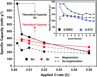
Fig. 2 Magnesiation/de-magnesiation capacities for Sn/Mg (■ black) and Bi/Mg ( red) half-cells at various C-rates. All half-cells were tested using an organohaloaluminate electrolyte. Inset – 10 cycles of a Sn/Mg half-cell at 0.005 C (■ black) and 0.01 C ( red) half-cells at various C-rates. All half-cells were tested using an organohaloaluminate electrolyte. Inset – 10 cycles of a Sn/Mg half-cell at 0.005 C (■ black) and 0.01 C ( blue) rates in the same electrolyte. blue) rates in the same electrolyte. | ||
The rate capability of Sn and Bi anodes was also tested in an organohaloaluminate electrolyte by varying the galvanostatic cycling rates between 0.002 C and 0.05 C (see ESI,† i and iii). Fig. 2 shows a comparison of the 1st cycle galvanostatic half-cell magnesiation and de-magnesiation capacities obtained for Sn and Bi anodes at the various C-rates. Fresh cells were used to investigate each C-rate. The Sn anodes displayed dramatic decreases in both magnesiation and de-magnesiation capacities at higher C-rates. While it is evident that the Sn anodes suffer from poor kinetics (limiting their capacities at faster C-rates), it is also important to note that at faster C-rates, the hysteresis between the magnesiation and de-magnesiation capacities diminishes. Further, the Sn anodes display decent cycling characteristics past the first cycle at various C-rates (Fig. 2, inset). Unlike Sn, Bi displayed acceptable magnesiation/de-magnesiation capacities and hysteresis at the same C-rates. Previous reports have shown that Mg3Bi2 can act as a fast-ion conductor.19 However, currently; such properties remain unexplored for Mg2Sn.
In order to highlight the compatibility and performance of a Sn anode in conventional battery electrolytes, a pre-magnesiated Sn (Mg2Sn) anode and a Chevrel phase (Mo6S8) cathode (see ESI,† iv) were coupled with 0.5 M Mg(N(SO2CF3)2)2 in DME, as a full-cell.20 The experiment was repeated with an organohaloaluminate electrolyte, so as to compare the performance of the two cells. Fig. 3 shows the first 10 cycles of both cells with 1st cycle capacities of 82 mA h g−1 (using a conventional electrolyte) and 83 mA h g−1 (using an organohaloaluminate electrolyte), followed by a drop in capacities from the second cycle. The 1st cycle magnesiation/de-magnesiation (of Mo6S8) curves are shown in the Fig. 3 inset, for both cells. While the voltage plateaus for the insertion/extraction of Mg2+ in Mo6S8 vary for the two full-cells, and a distinct overcharge capacity for the cell cycled using the organohaloaluminate electrolyte is observed (both observations remain under investigation), the performance of both cells during these 10 cycles was found to be comparable. The voltage profiles for Mg2+ insertion/extraction remain predictably lower than those previously reported for a Mo6S8/Mg metal anode full-cell, due to the use of the insertion-type Sn anode.4 The experiment highlighted in Fig. 3 verifies the concept of using insertion-type anodes (like Sn) with conventional battery electrolytes.
![The first 10 cycles for a [Mo6S8–conventional electrolyte–Mg2Sn] full-cell (■ black) and a [Mo6S8–organohaloaluminate electrolyte–Mg2Sn] full-cell ( blue); inset – 1st cycle voltage profiles for each full-cell.](/image/article/2013/CC/c2cc34673g/c2cc34673g-f3.gif) | ||
Fig. 3 The first 10 cycles for a [Mo6S8–conventional electrolyte–Mg2Sn] full-cell (■ black) and a [Mo6S8–organohaloaluminate electrolyte–Mg2Sn] full-cell ( blue); inset – 1st cycle voltage profiles for each full-cell. blue); inset – 1st cycle voltage profiles for each full-cell. | ||
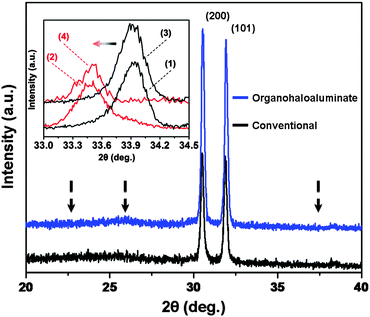
Since the capacity observed in Fig. 3 was limited by the weight of the cathode active material (Mo6S8) and not by the weight of the anode active material (Sn), two additional Mo6S8/Mg2Sn full-cells were fabricated using both previously used electrolytes (organohaloaluminate and conventional). Here, the loading content of Mo6S8 was increased so that its gravimetric capacity matched that of Sn. Mg2+ was extracted from Mg2Sn and inserted into Mo6S8via the application of +0.1 V for 72 hours (see ESI,† vi). The XRD spectra shown in Fig. 4 provide evidence for the complete magnesiation of Mo6S8 (inset) and complete de-magnesiation of Mg2Sn, for both cells. While galvanostatic full-cell cycling experiments continue, these initial data suggest that the entire capacity of Sn may be utilized for Mg-ion batteries under the correct circumstances.
 | ||
| Fig. 4 XRD spectra of de-magnesiated Mg2Sn from organohaloaluminate (blue) and conventional (black) electrolytes (Mg2Sn peak positions marked with arrows). Inset – XRD spectra showing a peak shift due to magnesiation (red) of Mo6S8 (black) in organohaloaluminate (peak shift 1 → 2) and conventional (peak shift 3 → 4) electrolytes. | ||
In this report, Sn powder films were used as simple, low cost electrodes to study the possibility of using high energy-density insertion-type anode materials for a Mg-ion battery system. We were able to show that a Sn anode could attain higher capacities (903 mA h g−1) and lower Mg2+ insertion/extraction voltages (+0.15/0.20 V) than those of previously reported Bi (384 mA h g−1, +0.23/0.32 V). More importantly, we were able to highlight the necessary compatibility and cyclability of the higher energy-density Sn anode with conventional battery electrolytes. The use of Sn as an insertion-type anode would allow for the evaluation of future, high voltage and high capacity Mg-ion battery cathodes using conventional battery electrolytes. Evidence from the Li-ion literature suggests that anodes such as Sn can attain high capacities at faster cycling rates via advancements in nanomaterials and anode architectures.21–25 Our current work with Sn is focused on improving its rate capability and cyclability by exploring such advancements, while identifying and understanding the mechanisms responsible for its poor coulombic efficiency.
The authors would like to thank Debra M. Sherman (DSimaging, LLC) and the Life Science Microscopy Facility at Purdue University along with Zhi Mei and the Central Instrument Facility (Department of Chemistry) at Wayne State University for their guidance and support with all microscopy related work.
Notes and references
- J.-M. Tarascon and M. Armand, Nature, 2001, 414, 359 CrossRef CAS.
- P. Novak, R. Imhof and O. Haas, Electrochim. Acta, 1999, 45, 351 CrossRef CAS.
- T. S. Arthur, N. Singh and M. Matsui, Electrochem. Commun., 2012, 16, 103 CrossRef CAS.
- D. Aurbach, Z. Lu, A. Schechter, Y. Gofer, H. Gizbar, R. Turgeman, Y. Cohen, M. Moshkovich and E. Levi, Nature, 2000, 407, 724 CrossRef CAS.
- M. Hayashi, H. Arai, H. Ohtsuka and Y. Sakurai, J. Power Sources, 2003, 119, 617 CrossRef.
- N. Jayaprakash, S. K. Das and L. A. Archer, Chem. Commun., 2011, 47, 12610 RSC.
- M. Matsui, J. Power Sources, 2011, 196, 7048 CrossRef CAS.
- Y. Nuli, Y. Zheng, F. Wang, J. Yang, A. I. Minett, J. Wang and J. Chen, Electrochem. Commun., 2011, 13, 1143 CrossRef CAS.
- T. Ichitsubo, T. Adachi, S. Yagi and T. Doi, J. Mater. Chem., 2011, 21, 11764 RSC.
- H. S. Kim, T. S. Arthur, G. D. Allred, J. Zajicek, J. G. Newman, A. E. Rodnyansky, A. G. Oliver, W. C. Boggess and J. Muldoon, Nat. Commun., 2011, 2, 427 CrossRef.
- D. Aurbach, J. Weissman, Y. Gofer and E. Levi, Chem. Rec., 2003, 3, 61 CrossRef CAS.
- Z. Lu, A. Schechter, M. Moshkovich and D. Aurbach, J. Electroanal. Chem., 1999, 466, 203 CrossRef CAS.
- T. D. Gregory, R. J. Hoffman and R. C. Winterton, J. Electrochem. Soc., 1990, 137, 775 CrossRef CAS.
- J. Muldoon, C. B. Bucur, A. G. Oliver, T. Sugimoto, M. Matsui, H. S. Kim, G. D. Allred, J. Zajicek and Y. Kotani, Energy Environ. Sci., 2012, 5, 5941 CAS.
- M. Winter, J. O. Besenhard, M. E. Spahr and P. Novak, Adv. Mater., 1998, 10, 725 CrossRef CAS.
- M. S. Whittingham, Chem. Rev., 2004, 104, 4271 CrossRef CAS.
- W.-J. Zhang, J. Power Sources, 2011, 196, 877 CrossRef CAS.
- H. Okamoto, Desk Handbook: Phase Diagrams for Binary Alloys, ASM International, Materials Park, OH, 2000, pp. 149 and 554 Search PubMed.
- A. C. Barnes, C. Guo and W. S. Howells, J. Phys.: Condens. Matter, 1994, 6, L467 CrossRef CAS.
- E. Lancry, E. Levi, A. Mitelman, S. Malovany and D. Aurbach, J. Solid State Chem., 2006, 179, 1879 CrossRef CAS.
- K. Y. Lee, Y. S. Jung and S. M. Oh, J. Am. Chem. Soc., 2003, 125, 5652 CrossRef CAS.
- N. Li and C. R. Martin, J. Electrochem. Soc., 2001, 148, A164 CrossRef CAS.
- Y. Jung, N. Singh and K.-S. Choi, Angew. Chem., Int. Ed., 2009, 48, 8331 CrossRef CAS.
- A. S. Arico, P. Bruce, B. Scrosati, J.-M. Tarascon and W. V. Schalkwijk, Nat. Mater., 2005, 4, 366 CrossRef CAS.
- P. G. Bruce, B. Scrosati and J.-M. Tarascon, Angew. Chem., Int. Ed., 2008, 47, 2930 CrossRef CAS.
Footnote |
| † Electronic supplementary information (ESI) available: Experimental methods (i–vi) along with SEM and TEM characterizations (vii–viii). See DOI: 10.1039/c2cc34673g |
| This journal is © The Royal Society of Chemistry 2013 |
