 Open Access Article
Creative Commons Attribution 3.0 Unported Licence
Unravelling the potential of sustainable aviation fuels to decarbonise the aviation sector†
Andres
Gonzalez-Garay
 a,
Clara
Heuberger-Austin
 b,
Xiao
Fu
b,
Mark
Klokkenburg
b,
Di
Zhang
ac,
Alexander
van der Made
*b and
Nilay
Shah
*a
b,
Xiao
Fu
b,
Mark
Klokkenburg
b,
Di
Zhang
ac,
Alexander
van der Made
*b and
Nilay
Shah
*a
aThe Sargent Centre for Process Systems Engineering, Imperial College London, SW7 2AZ London, UK. E-mail: n.shah@imperial.ac.uk
bShell Global Solutions International B.V., Shell Technology Centre Amsterdam, Royal Dutch Shell, 1031 HW Amsterdam, The Netherlands. E-mail: alexander.vandermade@shell.com
cCentre for Environmental Policy, Imperial College London, SW7 1NA London, UK
First published on 14th June 2022
Abstract
The aviation industry is responsible for approximately 2% of the total anthropogenic greenhouse gas emissions. With an expected four to six-fold growth by 2050, increased attention has been paid to reduce its carbon footprint. In this study, we analyse the requirements to promote Sustainable Aviation Fuels (SAFs) from solar energy to reduce the emissions of the sector. Using a discrete spatio-temporal mathematical description of the region of Spain, we present the key elements required to produce jet fuel via Fischer–Tropsch (FT) and Methanol to fuels (MtF). We have found that solar PV, electricity storage, and alkaline water electrolysis are the key drivers for the performance of solar SAFs while the optimal location of the facilities is driven by the availability of solar radiation, underground H2 storage, and high jet fuel demand. We show that the constant supply of H2 requires an over sizing of technologies, which in turn decreases the utilisation of solar panels and electrolysers. While higher usage rates could be attained by a constant supply of electricity (e.g., via the electricity grid), the use of renewable sources is essential to guarantee a reduction in CO2 emissions compared to fossil-based jet fuel. We found that production costs in 2020 per kgfuel in Spain varied from 3.90 € (MtF) to 4.95 € (FT) using solar radiation as a sole source of energy and a point source of CO2, cutting CO2 life cycle emissions by ∼25% compared to their fossil-based counterpart (2.5–2.7 kgCO2eq per kgfuel). Potential technological improvements could reduce jet fuel production costs to 2.5–3.3 € per kgfuel for CO2 point sources while emissions could reach ∼1.0 kgCO2eq per kgfuel. Ultimately, the impact of these routes in the cost of a flight ticket would result in a minimum increase of 100–150% at present and 40–80% by 2050, accounting for current projections on technologies and carbon prices. This shows that future minimum carbon taxes of 500 € per tCO2 would be required for SAFs to become competitive.
Broader contextThe transition to establish a carbon-neutral society requires a deep transformation of energy vectors. However, the decarbonisation of the aviation sector faces limited technological options able to move away from carbon-based fuels. While the Covid-19 pandemic has caused an unprecedented reduction in demand for air travel, it is expected that the sector will reach similar pre-pandemic levels in the next 2–3 years and continue to grow thereafter. Being under an equally increasing pressure to reduce its contribution to climate change in pursue of the Paris Agreement’s targets, the sector requires efficient strategies to deploy sustainable aviation fuels. In this context, alternatives emerge which differ in resources and technological routes, with little understanding of the requirements of the transition to support a net zero sector. This lack of knowledge expands to the impact that geographical constraints impose over resources consumption and storage availability. This investigation presents a holistic assessment for the regional conversion of solar-based energy into sustainable aviation fuels, accounting for conventional and emerging processing technologies integrated within the production value chains. We compare the Fischer–Tropsch and Methanol to fuels production routes and identify the regional implications to resource consumption required to satisfy energy requirements. Our analysis presents the scale of technology deployment required, regional drivers for network deployment, impact that technological learning would represent in the future performance of solar E-fuels, and the effect over the final consumer through the cost of a flight ticket. |
1 Introduction
The Paris agreement has the objective to maintain the increase of the global average temperature well below 2 °C. As a consequence, emissions should reach their peak as soon as possible and reduce rapidly thereafter, reaching net-zero practices in the second half of the century.1 This will require a deep transformation of energy vectors and industrial practices, from which the transport sector plays a key role in reaching a low-carbon society. In particular, the aviation sector faces additional challenges in the abatement of CO2 emissions given its high reliance on fossil fuels and expected growth in comparison to the average growth of other sectors. While global CO2 emissions grow annually by ∼3%, the emissions of the aviation sector showed an average increase of 5% in recent years (2013–2018). At this pace, emissions in 2040 would increase by 150% compared to those in 2020.2At present, the aviation industry is responsible for 2–3% of global CO2 emissions, in addition to other environmental problems. According to the IATA,3 the aviation sector consumed 350 Mt of fuel in 2019, which resulted in 1.09 GtCO2. However, these emissions consider only the combustion of jet fuel and when its production and airport operations are considered, the total CO2 emissions accounted for ∼1.29 GMtCO2.4–6 The International Civil Aviation Organisation (ICAO)7 reported scenarios for the abatement of CO2 emissions of the aviation industry, including technological improvements, improved air traffic management and infrastructure use, and alternative fuels. According to Doliente et al.,8 airframe and engine manufacturers have made significant technological leaps including lighter and stronger composite materials, new innovative aircraft designs with improved aerodynamics, and incrementally more efficient engines. For example, 15 billion litres of fuel and 80 MtCO2 were saved by retrofitting wing tip devices to the wings of over 5000 existing aircraft. By using weight reduction measures on cargo containers, CO2 emissions decreased by 10 ktCO2 per year. These improvements allow greater efficiency in mileage and lower fuel consumption during travel. However, these incremental changes in an already mature engine technology, along with the long lifetime (>25 years) of existing fleets, point toward alternative fuels as a much faster and potentially more cost-effective option to reduce emissions.
Sustainable aviation fuels (SAFs) are fuels with similar chemistry to conventional jet fuel but they are produced from renewable sources, and therefore, have the potential to reduce the lifecycle emissions of the fuel. In this context, different alternatives are being considered in the short-, medium-, and long-term for the aviation industry.7,9 For instance, biofuels are already being produced and have been used in more than 150![[thin space (1/6-em)]](https://www.rsc.org/images/entities/char_2009.gif) 000 commercial flights,10 with second generation technologies expected to boost their production in the coming decade.9 Another alternative relies on Power-to-Liquids (PtL), where renewable electricity is used to power electrocatalytic technologies to produce chemicals and fuels.11–13 These routes are not at a commercial scale yet but could gain traction by 2050.9 According to the ICAO,7 100% demand of jet fuel by 2050 could be met using SAFs, cutting emissions by 63%. However, the production level required could only be achieved with extremely large capital investments and substantial policy support. The cost of conventional jet fuel is highly dependent on the cost of oil, which despite cost uncertainties, results in production costs between 0.47 and 0.80 € per kgJF.3,10 In contrast, costs of aviation biofuels have been estimated to be between 0.75 and 1.75 € per kgJF.10 While these costs also depend on multiple factors, they are not expected to decrease significantly, in addition to uncertainties related to their lifecycle CO2 emissions, water and land use, and potential competition with food crops. In the PtL route, jet fuel can be produced using CO2 captured from a point source (PSC) or direct air capture (DAC) in combination with electrocatalytic H2via processes such as Fischer–Tropsch (FT) or Methanol-to-Fuels (MtF). At present, these routes present even higher costs than biofuels, with values reported to be 3.2–3.8 € per kgJF for PSC and 4.2–6.6 € per kgJF for DAC. These costs, however, are expected to decrease by almost 60% by 2050.11–13 Given the urgency to reduce the emissions of the sector, an additional alternative relies on the use of carbon offsetting. For instance, aiming to stabilise CO2 emissions at 2020 levels, the European Commission introduced the Carbon Offsetting and Reduction Scheme for International Aviation (CORSIA). In a recent analysis by Becattini et al.,13 this route results in the most cost effective alternative, with costs of 0.75 € per kgJF for PSC (60 € per tCO2) and 2.32 € per kgJF for DAC (578 € per tCO2). In addition, this route results in significantly less energy-intensive processes compared to PtL routes. However, increasing carbon taxes and social pressure to avoid fossil fuels could prevent this option from becoming a permanent solution.
000 commercial flights,10 with second generation technologies expected to boost their production in the coming decade.9 Another alternative relies on Power-to-Liquids (PtL), where renewable electricity is used to power electrocatalytic technologies to produce chemicals and fuels.11–13 These routes are not at a commercial scale yet but could gain traction by 2050.9 According to the ICAO,7 100% demand of jet fuel by 2050 could be met using SAFs, cutting emissions by 63%. However, the production level required could only be achieved with extremely large capital investments and substantial policy support. The cost of conventional jet fuel is highly dependent on the cost of oil, which despite cost uncertainties, results in production costs between 0.47 and 0.80 € per kgJF.3,10 In contrast, costs of aviation biofuels have been estimated to be between 0.75 and 1.75 € per kgJF.10 While these costs also depend on multiple factors, they are not expected to decrease significantly, in addition to uncertainties related to their lifecycle CO2 emissions, water and land use, and potential competition with food crops. In the PtL route, jet fuel can be produced using CO2 captured from a point source (PSC) or direct air capture (DAC) in combination with electrocatalytic H2via processes such as Fischer–Tropsch (FT) or Methanol-to-Fuels (MtF). At present, these routes present even higher costs than biofuels, with values reported to be 3.2–3.8 € per kgJF for PSC and 4.2–6.6 € per kgJF for DAC. These costs, however, are expected to decrease by almost 60% by 2050.11–13 Given the urgency to reduce the emissions of the sector, an additional alternative relies on the use of carbon offsetting. For instance, aiming to stabilise CO2 emissions at 2020 levels, the European Commission introduced the Carbon Offsetting and Reduction Scheme for International Aviation (CORSIA). In a recent analysis by Becattini et al.,13 this route results in the most cost effective alternative, with costs of 0.75 € per kgJF for PSC (60 € per tCO2) and 2.32 € per kgJF for DAC (578 € per tCO2). In addition, this route results in significantly less energy-intensive processes compared to PtL routes. However, increasing carbon taxes and social pressure to avoid fossil fuels could prevent this option from becoming a permanent solution.
While all these assessments provide valuable insights, most of them rely on general scenarios. For instance, the use of average capacity factors for electricity production or the possibility to operate technologies at a more flexible and intermittent way, even in the case of continuous processes such as FT. These assumptions result not only in economic and environmental impacts with higher uncertainties but also in potentially optimistic assessments that can neglect more realistic operating conditions, such as the need for storage of intermediate products. In this context, supply chain models present a viable option to reduce such uncertainties by jointly modelling spatio-temporal representations, availability of resources, technologies selection, and network design.14,15 Aiming to build on these approaches and reduce uncertainties during the assessment of SAFs, we propose the use of a bottom-up supply chain model applied to the production of jet fuel from solar energy. Defined as a Resource-Technology Network (RTN), the model accounts for the availability of resources in a given region across multiple periods, to then deploy the most suitable technologies for the production of jet fuel, where we include the FT and MtF routes. The technologies included rely on process modelling and optimisation that can help to identify synergies between them, and therefore, generate highly-integrated and energy-efficient production routes. Ultimately, the model provides a network with minimal cost and environmental impact, as monetary factors are introduced in the form of a carbon tax. The RTN model is applied to Spain, which is a region with high potential to deploy solar energy and has air traffic with over two million operations per year.14,16
This work is organised as follows. We first present the definition of the spatio-temporal representation defined in the case study. We then move to the RTN model, defining the resources and technologies considered in the superstructure. We also present the mathematical formulation of the model and the assumptions behind the accounting of lifecycle CO2 emissions. In Section 4, we discuss the results of the network for the current status of the technologies while Section 5 includes multiple sensitivity analyses where a performance forecast is also discussed. In Section 6, we report a comparison of our results with other SAFs and the implications in the cost of a flight ticket to finally present the conclusions of our analysis.
2 Spatio-temporal representation
2.1 Space and demand
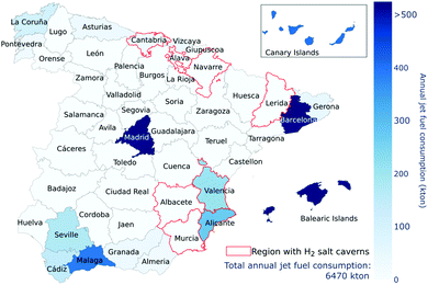
The demand of jet fuel, availability of resources and technologies are distributed across Spain using a cell representation that includes 36 cells of 120 km each. The total annual demand of jet fuel defined in the model is that of 2017, the year in which Spain consumed a total of 138![[thin space (1/6-em)]](https://www.rsc.org/images/entities/char_2009.gif) 430 bpd (6.47 Mt per year) of jet fuel, transported more than 275 million people, and had roughly two million arrivals and departures.16–18 While the model was forced to satisfy the full demand of jet fuel in all the scenarios, a minimum demand was defined for the regions located in the mainland. This minimum demand was defined by those airports whose operations where higher than 1% of the total of operations or transported more than 1 million passengers.16 An additional consideration is that of the Canary and Balearic Islands, as they are not part of Spain's mainland. In the case of the Balearic Islands, the region accounts for 16% of the total operations and 15% of the traffic of passengers. Here, the demand for jet fuel is added to the region of Barcelona without accounting for further transportation to the islands. In the case of the Canary Islands, approximately 20% of the total operations took place across its eight airports, which also accounted for 17% of the total traffic of passengers. Here, we assume that the demand for jet fuel has to be fulfilled by the network in the mainland, although their specific contribution is not fixed to any particular province. That is, their demand is not accounted for to define the minimum regional demand to be satisfied. Under these assumptions, 23 out of the 48 active airports in Spain are used to define the minimum regional demand of jet fuel shown in Fig. 1, which accounts for 78% of the total demand. The list of airports included is reported in the ESI.†
430 bpd (6.47 Mt per year) of jet fuel, transported more than 275 million people, and had roughly two million arrivals and departures.16–18 While the model was forced to satisfy the full demand of jet fuel in all the scenarios, a minimum demand was defined for the regions located in the mainland. This minimum demand was defined by those airports whose operations where higher than 1% of the total of operations or transported more than 1 million passengers.16 An additional consideration is that of the Canary and Balearic Islands, as they are not part of Spain's mainland. In the case of the Balearic Islands, the region accounts for 16% of the total operations and 15% of the traffic of passengers. Here, the demand for jet fuel is added to the region of Barcelona without accounting for further transportation to the islands. In the case of the Canary Islands, approximately 20% of the total operations took place across its eight airports, which also accounted for 17% of the total traffic of passengers. Here, we assume that the demand for jet fuel has to be fulfilled by the network in the mainland, although their specific contribution is not fixed to any particular province. That is, their demand is not accounted for to define the minimum regional demand to be satisfied. Under these assumptions, 23 out of the 48 active airports in Spain are used to define the minimum regional demand of jet fuel shown in Fig. 1, which accounts for 78% of the total demand. The list of airports included is reported in the ESI.†
2.2 Temporal representation
Aiming to better capture the variance in solar radiation of the country, the temporal representation of the model includes three major periods (seasons) and four minor periods (days). The length of each period is defined using the solar radiation profiles retrieved for the Nomenclature of Territorial Units for Statistics level 2 (NUTS-2) and reported in Fig. A1–A3 (ESI†).19 In terms of seasonality, the trends observed resulted in 115 days in summer, 115 days in mid-season, and 135 days in winter. Similarly, the daily representation accounts for 10 h during the night period, 4 h during morning, 6 h during noon, and 4 h during the afternoon. The radiation profiles used considered a 10 year period (2010 to 2019), reporting a yearly average capacity factor of 0.168. The further allocation of the demand for each region across summer, winter, and mid-season was based on the number of operations reported for each of the months pertaining to each season (Fig. B1 in the ESI†).16,17 The allocation of the demand for each region across summer, winter, and mid-season also considered the number of operations reported for each of the months pertaining to each season. In terms of the daily operation, we assumed that 85% of the demand was satisfied at the same hourly rate during the morning, noon, and afternoon periods while the remaining 15% was satisfied over the night period. We present further details about the selection of the periods, solar radiation profiles, daily capacity factors, airport operations profiles, and final fuel demand in the ESI.†3 Resource-technology network (RTN) model
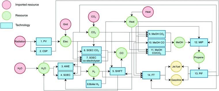
Fig. 2 shows a scheme of the RTN model developed, which comprises a total of 14 technologies and 10 resources (intermediates/final products), where the final products are jet fuel and gasoline produced via FT and MtF.3.1 Resources
Resources refer to any material or energy stream considered in the value chain: imported resources, intermediates, end-products and co-products. A resource can be consumed or produced by a technology, transported from one cell to another, imported to the system and stored when necessary. The model allows the import of five resources into the network, according to Table 1.3.2 Technologies
A technology represents any type of process plant that can convert one or more input resources to one or more output resources. The RTN model includes 14 technologies divided in two subsets: non-scalable (1–8) and scalable (9–14). Non-scalable technologies consider fixed capital costs regardless of their level of deployment while scalable technologies benefit from economies of scale and include three different production scales, aiming to capture their non-linear performance as they are scaled. Data for non-scalable technologies was retrieved from the literature while scalable technologies were modelled and optimised using commercial process simulators and standard cost correlations available.24–26 Fixed operating costs were assumed as a fraction of the capital costs and all the cost values were expressed in €2020. Technologies inputs and outputs are reported in Table 2 while direct CO2 emissions along with capital and operating costs are reported in Table 3.| Technology | Radiation | Elec (MW) | Heat (MW) | CO2 (kg) | CO (kg) | H2 (kg) | MeOH (kg) | H2O (kg) | C3H6 (kg) | Jet fuel (kg) | Gasoline (kg) |
|---|---|---|---|---|---|---|---|---|---|---|---|
| BH | 1 | −30.3 | |||||||||
| CSP | −1 | 1 | |||||||||
| PV | −1 | 1 | |||||||||
| AWE | −0.060 | 1 | −10.11 | ||||||||
| SOEC | −0.064 | −0.014 | 1 | −9.01 | |||||||
| SHIFT | −1.2 × 10⁻³ | −1.58 | 1 | −0.072 | 0.645 | ||||||
| SOEC CO2 | −3.4 × 10⁻⁴ | −4.0 × 10⁻⁴ | −1.571 | 1 | |||||||
| SOEC CO-ele | −0.0102 | −1.5 × 10⁻³ | −1.571 | 1 | 0.1429 | −1.286 | |||||
| ME CO2 | −1.6 × 10⁻⁵ | 1.1 × 10⁻³ | −1.509 | −0.2032 | 1 | 0.5789 | |||||
| ME CO | 1.2 × 10⁻⁴ | 1.2 × 10⁻³ | −0.085 | −0.866 | −0.1278 | 1 | 0.001 | ||||
| ME CO/CO2 | −2.0 × 10⁻⁵ | 5.8 × 10⁻⁴ | −0.264 | −0.708 | −0.137 | 1 | 0.089 | ||||
| FT | −1.4 × 10⁻⁴ | 0.807 | −3.282 | −0.408 | 1 | 0.3038 | |||||
| MTP | 7.4 × 10⁻⁶ | 1.1 × 10⁻⁴ | −2.345 | 1 | |||||||
| PTF | 1.6 × 10⁻⁴ | −2.07 | 1 | 1.057 |
| Technology | CAPEX (€M) | OPEX (€M) | CO2 (tCO2 per unit) | ||
|---|---|---|---|---|---|
| s 1 | s 2 | s 3 | |||
| BH (MW h) | 0.249 | — | — | 9.5 × 10⁻⁷ | — |
| PV (MW h) | 0.810 | — | — | 7.9 × 10⁻⁷ | 0.062 |
| CSP (MW h) | 5.766 | — | — | 5.3 × 10⁻⁶ | 0.043 |
| AWE (kg) | 5.9 × 10⁻² | — | — | 4.7 × 10⁻⁸ | — |
| SOEC (kg) | 2.4 × 10⁻¹ | — | — | 1.3 × 10⁻⁷ | — |
| SHIFT (kg) | 2.5 × 10⁻³ | — | — | 2.1 × 10⁻⁹ | — |
| SOEC CO2 (kg) | 3.0 × 10⁻² | — | — | 2.7 × 10⁻⁸ | — |
| SOEC CO-ele (kg) | 3.36 | — | — | 3.0 × 10⁻⁶ | — |
| ME CO2 (kg) | 4.2 × 10⁻³ | 3.2 × 10⁻³ | 2.7 × 10⁻³ | 2.2 × 10⁻⁸ | 5.21 × 10⁻⁵ |
| ME CO (kg) | 1.0 × 10⁻³ | 7.9 × 10⁻⁴ | 6.7 × 10⁻⁴ | 5.3 × 10⁻⁹ | 1.33 × 10⁻⁴ |
| ME CO/CO2 (kg) | 1.8 × 10⁻³ | 1.4 × 10⁻³ | 1.2 × 10⁻³ | 9.1 × 10⁻⁹ | 1.22 × 10⁻⁴ |
| FT (kg) | 1.3 × 10⁻² | 1.1 × 10⁻² | 7.4 × 10⁻³ | 7.8 × 10⁻⁸ | 1.31 × 10⁻⁴ |
| MTP (kg) | 3.2 × 10⁻³ | 2.1 × 10⁻³ | 1.3 × 10⁻³ | 1.8 × 10⁻⁸ | 7.92 × 10⁻⁵ |
| PTF (kg) | 1.6 × 10⁻³ | 1.0 × 10⁻³ | 6.6 × 10⁻⁴ | 1.4 × 10⁻⁸ | 2.46 × 10⁻⁵ |
Alkaline electrolysis (AWE). This process can produce hydrogen above 99.5% purity using an alkaline medium (25–30% KOH). A minimum operating load of 30% is assumed, implying that electricity supply has to remain at this minimum level even when solar radiation is not available.28,29 The reactions taking place occur at 85 °C and we assume an output pressure of 33 bar:
| 2H2O → 2H2 + O2 | (R1) |
Solid oxide electrolyser cells for H2O electrolysis (SOEC). These systems use solid ion-conducting ceramics as the electrolyte, which allows operations at significantly higher temperatures with high electrical efficiency and low material costs. The overall reaction for this process is the same as for alkaline electrolysis. However, the reactions taking place differ in the anode and cathode, with temperatures typically within the range of 500–900 °C.30 The system used here assumed a temperature of 800 °C and 21 bar.
Water–gas-shift reaction (SHIFT). CO2 must be processed via the SHIFT reaction at temperatures around 800 °C, having as a result a mixture of CO and unreacted CO2 and H2:
| CO2 + H2 ↔ H2O + CO | (R2) |
![[thin space (1/6-em)]](https://www.rsc.org/images/entities/char_2009.gif) :
:![[thin space (1/6-em)]](https://www.rsc.org/images/entities/char_2009.gif) CO2 of 3. If pure CO is desired, the products of the SHIFT reaction should undergo further treatment. In this study, this analysis is disregarded and the output of the SHIFT reaction is directly fed into the downstream processes.
CO2 of 3. If pure CO is desired, the products of the SHIFT reaction should undergo further treatment. In this study, this analysis is disregarded and the output of the SHIFT reaction is directly fed into the downstream processes.
Electrocatalytic reduction of CO2 (SOEC CO2). In this technology, we assume the design proposed by Kleiminger,31 who makes use of a micro-tubular reactor with a nickel wire current collector operated at 800 °C and 1 bar: Overall:
 | (R3) |
The reactor had a cell potential difference of 1.5 V and current density of −1 A cm−2. After the reaction, a CO/CO2 separation unit is included based on cryogenic liquefaction.
SOEC co-electrolysis of H2O–CO2 (SOEC CO-ele). SOEC systems can also operate in the co-electrolysis mode producing syngas from water steam and CO2, resulting in the following overall reaction:
| nCO2 + mH2O → nCO + mH2 + (m + n)/2O2 | (R4) |
Hydrogenation of CO2 (MEOH CO2), CO (MEOH CO), and a mixture CO2/CO 25/75 wt% (MEOH CO2/CO). The production of methanol is given by the following reactions:
| CO + 2H2 ↔ CH3OH | (R5) |
| CO2 + 3H2 ↔ CH3OH + H2O | (R6) |
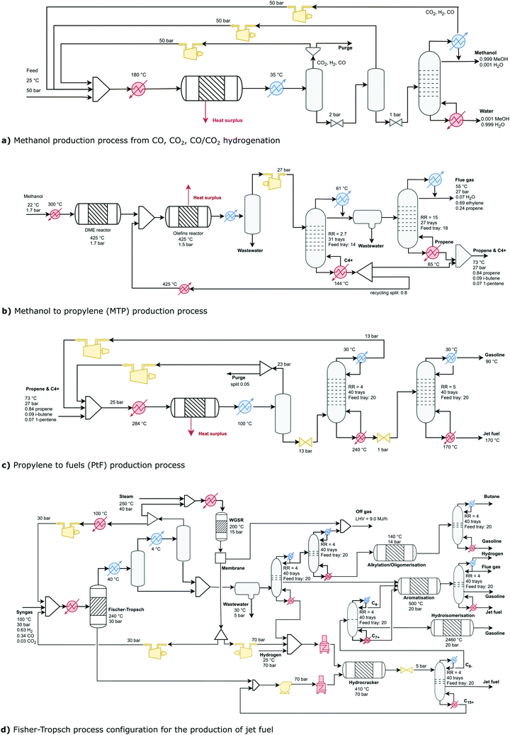
Whether the feed to the process is CO2, CO, or CO2/CO, the production process is identical, which was modelled in Aspen HYSYS (Fig. 3a).33 The reaction is exothermic and the heat surplus is coupled with a Rankine cycle to cogenerate electricity. The output of the reactor is then separated in a series of flash tanks, where the gases are recycled to the reactor while the liquids are sent to a distillation column. Here, water and methanol are separated, obtaining methanol with a purity >99.5%. Temperatures and pressures of the reactor and distillation column were optimised for each feedstock based on their total annualised cost (TAC).26 While CO2 and CO are assumed pure in MEOH–CO2 and MEOH–CO, respectively, the blend CO/CO2 assumes 75/25 wt% in MEOH–CO/CO2. The three production scales considered are: 50 tMEOH per h, 100 tMEOH per h, and 150 tMEOH per h.
Methanol to propylene (MtP). The production of olefins from methanol is made through the conversion of both methanol and dimethyl ether (DME). Therefore, methanol first reacts in a reversible reaction to produce DME and water. The resulting methanol, DME, and water then react to produce olefins in the range C2–C5. The mechanism followed is described by a ZSM-5 catalyst with higher selectivity toward intermediate olefins, such as propylene.34 The process used in the RTN model was modelled using Aspen HYSYS (Fig. 3b).35 Here, methanol is sent to an adiabatic DME reactor to then be fed into the MtP reactor together with recycled olefins. Methanol/DME reach a conversion higher to 99%, with propylene as the predominant hydrocarbon product. The olefin-containing streams are sent back to the main synthesis loop as an additional propylene source. To avoid accumulation of inert materials in the loop, a small purge is required for light-ends and the C4/C5 cut. The main reaction is exothermic, and a Rankine cycle is included to cogenerate electricity. The flue gas stream is burned, and the heat used to satisfy the heating demand of the process. While the process could also generate C4 and C5 olefins, we feed that stream along with propylene to the PtF process. The three scales considered for the production of propylene are 50 tC3H6 per h, 150 tC3H6 per h, and 300 tC3H6 per h.
Methanol to fuels (MtF) via propylene oligomerisation (PtF). In the PtF process, propylene (along with the C3+ products) is sent to an oligomerisation reactor to produce gasoline and jet fuel. To set up the process, an equilibrium reactor was modelled following the experimental results reported by Quann et al.,36 which correspond to propylene oligomerisation at 24 bar and 284 °C using a ZSM-5 zeolite in a fixed bed reactor. Fig. 3c shows the flowsheet of the process. After the reactor, a series of flash separators are used to recover unreacted propylene, the first operating at 23 bar and 100 °C, and the second operating at 2 bar and 92 °C. Before recycling the stream of the first flash separator, a purge is included. After the flash separators, a distillation column is used to remove the propylene and butane of the products. A second column separates gasoline (top) and jet fuel (bottoms), with a share of 50 wt%.37 The process was modelled in Aspen Plus v9 using the Predictive Soave–Redlich–Kwong equation of state. Three scales were considered for the production of jet fuel: 50 tJF per h, 150 tJF per h, and 300 tJF per h.
Fischer–Tropsch (FT). The Fischer–Tropsch (FT) process is a collection of chemical reactions that converts a mixture of carbon monoxide and hydrogen into predominantly linear hydrocarbons. Fig. 3d presents a simple refinery model to maximise jet fuel production,38 which includes four additional chemical conversions to produce jet fuel from FT material.38,39 After the FT reactor, most unreacted gases are recycled back to the process while the rest are sent to a WGSR to increase the amount of hydrogen by converting CO and water at 200 °C and 15 bar. A small amount of this hydrogen is sent to the hydrocracker while the rest is recycled back to the FT reactor. The hydrocarbons in the range C1–C8 leaving the FT reactor enter a series of distillation columns and are sent to combustion (C2–C3), alkylation/oligomerisation (C4–C5), or aromatisation (C6–C8). Liquid hydrocarbons leaving the FT reactor are sent to the hydrocracker along with the C9+ hydrocarbons recovered from the gas stream. The hydrocracker operates at 410 °C and 70 bar producing hydrocarbons from C4 to C30+. The product stream is sent to a distillation column where hydrocarbons within the jet fuel range are recovered. The stream with C8− is sent to a second distillation column, where products are sent to hydro-isomerisation (C5–C6) and aromatisation (C7+ and C4). C15+ hydrocarbons are recovered from the distillation column and recycled back to the hydrocracker. The process results in the production of jet fuel and gasoline at a ratio 3
![[thin space (1/6-em)]](https://www.rsc.org/images/entities/char_2009.gif) :
:![[thin space (1/6-em)]](https://www.rsc.org/images/entities/char_2009.gif) 1. The process was modelled in Aspen Plus v9 using the Predictive Soave–Redlich–Kwong equation of state. The FT reactor and hydrocracker follow the models reported by Graciano et al.40 while the remaining units were modelled using equilibrium reactors. Costs for these units were based on inlet mass flowrate.24 The off-gas stream is burned and the heat used to satisfy the demand of the process while the heat released by the Fischer–Tropsch reactor was coupled with a Rankine cycle.39 Three scales were considered for the production of jet fuel: 50 tJF per h, 150 tJF per h, and 300 tJF per h. A unit for carbon capture using MEA was also included in the model to sequestrate the CO2 emissions generated from the combustion of the purge stream.41
1. The process was modelled in Aspen Plus v9 using the Predictive Soave–Redlich–Kwong equation of state. The FT reactor and hydrocracker follow the models reported by Graciano et al.40 while the remaining units were modelled using equilibrium reactors. Costs for these units were based on inlet mass flowrate.24 The off-gas stream is burned and the heat used to satisfy the demand of the process while the heat released by the Fischer–Tropsch reactor was coupled with a Rankine cycle.39 Three scales were considered for the production of jet fuel: 50 tJF per h, 150 tJF per h, and 300 tJF per h. A unit for carbon capture using MEA was also included in the model to sequestrate the CO2 emissions generated from the combustion of the purge stream.41
3.3 Life cycle CO2 emissions
The model considers emissions released throughout the life cycle of the fuels (cradle-to-grave). Emissions for imported resources include CO2, electricity from the grid, and heat from natural gas (Table 1). Emissions of intermediate resources are retrieved from the mass balances of the corresponding technologies (Table 3). In terms of equipment manufacturing, emissions typically represent negligible contributions as they are amortised over the production of the plant's lifetime.26 However, this is not the case for PV and CSP, which involve energy-intensive and fossil-based processes behind the manufacture of panels. This, in combination with their lower capacity factors, result in emissions of 62 kgCO2eq per MW per h for PV and 43 kgCO2eq per MW per h for CSP.42–44 In both cases, emissions are amortised accounting for the electricity generated throughout the entire lifetime of the solar plants (30 years) and the emissions released during their installation and operation.42–44 To account for the combustion stage, no credits were given to the CO2 being used as a feedstock as it would be released again to the atmosphere. The CO2 embedded in the capture process i.e. CO2 not captured and that coming from energy consumption was accounted for with a value of 0.12 kgCO2eq per kg of CO2 captured.21 A scheme showing the lifecycle CO2 emissions of the processes is presented in the ESI.†3.4 Transport and storage
Pipelines or tank trucks are considered to transport H2, CO, CO2, MeOH, propylene, and fuels. While some transport options are not typically available for all the resources, these options aim to find cost-optimal alternatives that might be later assessed according to real-world constraints. The capital costs for the pipeline network is 0.57 M€ per km while tank transportation has a cost of 0.53 € per km per t and releases 4.0 × 10⁻⁵ kgCO2eq per km.45,46 For the electrical energy storage, a generic stationary system is applied, which incurs 225 € per kW of capital costs.28 For H2 storage, Spain has the availability of salt caverns in the north and east regions of the country (Fig. 1), with assumed capital costs of 200 € per kgH2.47 For the remaining regions, we assumed a cost of 1200 € per kgH2, representative of a high pressure compressed system operating at 200 bar.47,48 Storage of jet fuel is made in atmospheric tanks incurring capital costs of 2 € per kgfuel.25,493.5 Modelling
The previous elements are combined through a series of equations resulting in a Mixed-Integer Linear Programming (MILP) formulation that is implemented in AIMMS v4.77 and solved using CPLEX v.20.1.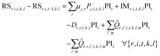 | (1) |
| NTj,i,l = NTj,i,l−1 + INVTj,i,l ∀j ∈ JUS, i, l | (2) |
| NTj,i,l,sS = NTj,i,l−1,sS + INVTSj,i,l,s ∀j ∈ JS, i, l, s | (3) |
The installed capacity of each technology is limited by a given lower/upper bound of each scale level in each cell:
| LTj,sSXi,j,l,s ≤ INVTSj,i,l,s ≤ U(j, s)TSX(i, j, l, s) ∀i ∈ JS, i, l, s | (4) |
For each cell i, any technology j at each investment time period l, only one scale can be selected:
 | (5) |
The production rate P of any technology j in each cell i is limited by the capacity and capacity factor of the available technology units:
 | (6) |
| Pj,i,t,k,l ≤ NTj,i,lCFj,t,k ∀j ∈ JUS, i, t, k, l | (7) |
| NSr,i,l = NSr,i,l−1 + INVSr,i,l ∀r ∈ RS, i, l | (8) |
The amount of the storage for any resource r at any time period should be limited by the installed capacity of the storage:
| RSr,i,t,k,l ≤ NSr,i,l ∀r ∈ RS, i, t, k, l | (9) |
![[Q with combining circumflex]](https://www.rsc.org/images/entities/i_char_0051_0302.gif) r,i,i′,t,k,l,tr. This variable is limited by a user-specified parameter Qmaxr,tr. A binary variable Yr,i,i′,l,tr = 1 indicates that the transportation method tr is allowed to transport resource r between cells i and i′ whereas Yr,i,i′,l,tr = 0 indicates that transport is not allowed.
r,i,i′,t,k,l,tr. This variable is limited by a user-specified parameter Qmaxr,tr. A binary variable Yr,i,i′,l,tr = 1 indicates that the transportation method tr is allowed to transport resource r between cells i and i′ whereas Yr,i,i′,l,tr = 0 indicates that transport is not allowed. | (10) |
 | (11) |
For each cell, its specific minimum demand requirement should also be met:
| Dr,i,t,k,l ≥ Dminr,i,t,k,l ∀r ∈ RP, i, t, k, l | (12) |
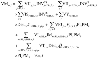 | (13) |
 | (14) |
The weighting factor for OBJWTCapEx,l is assumed to be 0.117, which is equal to the capital recovery factor for 20 years with a 10% interest rate. The OBJWTOpEx,l takes a value of 1 based on an annual operation, while the weighting factor for the CO2 emissions OBJWTCO2,l is based on a carbon tax with a value of 54 € per tCO2.50
3.6 Scenarios
All the scenarios reported satisfy the total demand of jet fuel using either the FT or MtF routes. The network design was determined using the RTN model according to two different scenarios for each route: no energy import (NE) and energy import (EI). In scenario NE, all the energy requirements were satisfied by solar technologies using hydrogen as a source of heat. This scenario does not account for any carbon tax. In contrast, scenario EI was allowed to import electricity from the grid and heat from natural gas. Here, a carbon tax of 54 € per tCO2 was included.51 These scenarios are further assessed under expected technology improvements and cost reductions toward 2050. Here, costs and emissions from solar PV, CSP, and AWE are modified following values reported in the literature.30,52–54 Similarly, the carbon tax is linearly increased up to 2050 in accordance to the Sustainable Development Scenario described by the IEA.554 Technology deployment and resource consumption
The results discussed in this section focus on the NE scenarios, which show potential to abate the emissions of the sector. As reported in Appendix E, scenarios EI release more than double CO2 emissions than BAU options (7.2–8.2 kgCO2eq per kgfuel and 3.6 kgCO2eq per kgfuel, respectively). Full results of the scenarios developed are reported in the ESI,† including an analysis to determine the imports of electricity that would keep emissions below BAU.4.1 Technologies for the production of jet fuel
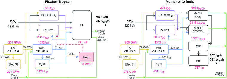
Fig. 4 shows the overall capacities required to satisfy the annual demand of jet fuel in Spain (6470 kt). In terms of electricity, both routes deploy solar PV as the preferred technology. The system includes electricity storage to maintain the operation of the system during the night periods, when AWE operate at their minimum load of 30%. The FT route deploys 251 GW h of solar PV producing a total of 298 TW h per year while the MtF route deploys 306 GW h of PV producing 361 TW h per year, representing an additional 21% to FT. While the MtF route requires a larger deployment of PV, the system also generates 57% more fuels on a mass basis (gasoline). The MtF route modelled has a mass yield to JF of 49%. However, yields up to 80% have been reported, a scenario that could reduce the infrastructure deployed for this route.36 The annual capacity factor of PV in both routes is ∼13.5%.In terms of hydrogen, both routes select AWE electrolysis and the corresponding storage to guarantee its supply downstream, as FT and MtF operate continuously. Following PV, the installed capacities for the hydrogen system are defined by the winter season, resulting in maximum production rates of 1082 and 1313 tH2 per h in FT and MtF, respectively. During this period, ∼50% of H2 is sent to the JF production trains while the remaining 50% goes to storage, resulting in an annual capacity factor of 51% for AWE. While more H2 is required in the MtF route, the net requirement per kgfuel is lower than the FT route, consuming 0.44 and 0.57 kgH2 per kgfuel in MtF and FT, respectively. This larger consumption of H2 in FT is caused by the heating requirements of the process (supplied by H2 in the NE scenarios) and the production of butene as a byproduct in the process. When electricity from the grid can be imported, the installed capacity of AWE decreases by 33%, allowing it to operate at full capacity during the night period when cheap electricity from the grid is available, increasing its annual capacity factor to 70%.
The production of jet fuel is given by the corresponding route. In the FT route, CO2 is consumed at a maximum rate of 3337 t h−1, being fed to the CO production technologies SHIFT and SOEC CO2. When both technologies operate, SHIFT consumes 3615 tCO2 per h while SOEC CO2 consumes 360 tCO2 per h. The remaining 638 tCO2 per h still required by the network are supplied by the CO2 captured after the combustion of the flue gas in the FT process. The production of jet fuel in MtF includes ME CO2 and ME CO/CO2 to produce MeOH. Here, the network identifies energy synergies between these routes, resulting in installed capacities of 606 and 3116 tMEOH per h for ME CO2 and ME CO/CO2, respectively. This route consumes 1737 tCO2 per h directly in the production of MeOH while the remaining 3467 tCO2 per h is used in the production of CO via SHIFT (3151 tCO2 per h) and SOEC CO2 (315 tCO2 per h). While the installed capacity of SOEC CO2 is 10% of the total CO production technologies, its annual contribution is only 4%. The reason being that SOEC CO2 operates during summer and mid-season, when it benefits from ‘free’ electricity available from the PV system, which does not operate at full capacity during these periods.
4.2 Distribution network
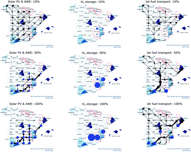
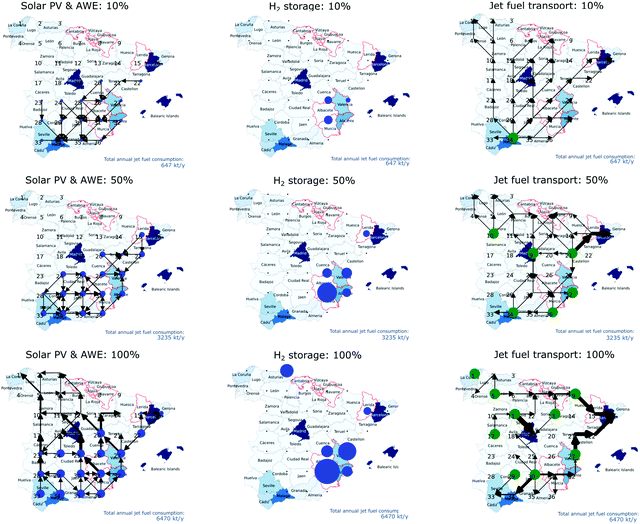
The main scenarios previously discussed were obtained assuming that 100% demand of jet fuel will be satisfied. To analyse the network design, we analysed three different penetration levels: 10%, 50%, and 100%. Therefore, the annual jet fuel demand was defined as 647 ktJF, 3235 ktJF, and 6470 ktJF. The demand of each cell was modified proportionally according to each scenario. The maximum level of deployment for PV was limited to 2, 10, and 20 GW accordingly for each scenario. In the discussion, only scenarios NE are considered given that scenarios EI result in greater costs and environmental footprint than BAU. The results show that the unitary production cost of the fuel and CO2 emissions present a minimal reduction as the demand increases (Section E in the ESI†). The reason for this is that non-scalable technologies (PV, AWE, and storage) have a larger contribution to the indicators and their contributions remain at similar levels across the scenarios. At larger production rates, scalable technologies benefit from economies of scale and reduce production costs by a low margin. Despite the small variation in production costs, the networks deployed show different operating modes, which are now discussed. Full costs and emissions for each case are reported in the ESI.†4.3 Economic and environmental performance
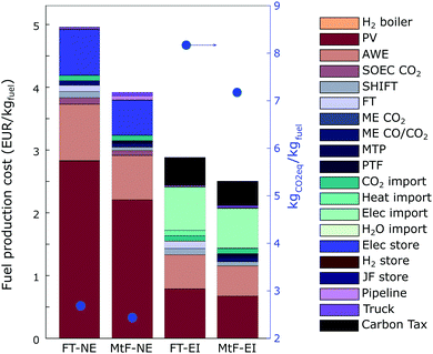
Fig. 7 shows the production costs per kgfuel for the scenarios under assessment, including their corresponding life cycle CO2 emissions. The life cycle emissions of the solar-based alternatives are between 2.44 and 2.69 kgCO2eq per kgfuel. While the reduction could be expected to be lower, the current production of solar panels is highly energy-intensive, having China as one of the main producers worldwide. As cleaner energy, and particularly electricity, is applied in the production of solar panels, the emissions embodied in PV are also expected to decrease, resulting in larger CO2 savings.![[thin space (1/6-em)]](https://www.rsc.org/images/entities/char_2009.gif) 743 M€, releasing 22.7 MtCO2eq, and producing 6.47 MtJF and 1.966 Mtgas. These costs represent 4.95 € per kgfuel with life cycle emissions of 2.69 kgCO2eq per kgfuel. From Fig. 7, capital costs represent 95% of the total cost with operating costs represent the remaining 5%. Among the capital costs, PV, AWE, and electricity storage are the main contributors, representing 50%, 26%, and 14%, respectively. Among the operating costs, 3% come from the fixed costs of operation while 2% from CO2, and less than 1% from water and transport of H2 and jet fuel. The 2.69 kgCO2eq per kgfuel of this scenario represent a reduction by 25% of current CO2 emissions embedded in the life cycle of the liquid fuels (3.60 kgCO2eq per kgJF). Under the assumptions used in the model, PV contributed with 2.12 kgCO2eq per kgfuel while the CO2eq embedded in the capture of imported CO2 resulted in 0.40 kgCO2eq per kgfuel. In terms of cost, this scenario is 7.5-fold more expensive than the oil-based jet fuel with carbon tax (0.66 € per kg), resulting in a cost of CO2 avoided of 4700 € per tCO2.
743 M€, releasing 22.7 MtCO2eq, and producing 6.47 MtJF and 1.966 Mtgas. These costs represent 4.95 € per kgfuel with life cycle emissions of 2.69 kgCO2eq per kgfuel. From Fig. 7, capital costs represent 95% of the total cost with operating costs represent the remaining 5%. Among the capital costs, PV, AWE, and electricity storage are the main contributors, representing 50%, 26%, and 14%, respectively. Among the operating costs, 3% come from the fixed costs of operation while 2% from CO2, and less than 1% from water and transport of H2 and jet fuel. The 2.69 kgCO2eq per kgfuel of this scenario represent a reduction by 25% of current CO2 emissions embedded in the life cycle of the liquid fuels (3.60 kgCO2eq per kgJF). Under the assumptions used in the model, PV contributed with 2.12 kgCO2eq per kgfuel while the CO2eq embedded in the capture of imported CO2 resulted in 0.40 kgCO2eq per kgfuel. In terms of cost, this scenario is 7.5-fold more expensive than the oil-based jet fuel with carbon tax (0.66 € per kg), resulting in a cost of CO2 avoided of 4700 € per tCO2.
![[thin space (1/6-em)]](https://www.rsc.org/images/entities/char_2009.gif) 956 M€, releasing 32.4 MtCO2eq and producing 6.47 MtJF and 6.837 Mtgas. This represents an investment 24% higher than the FT process but producing fuels 23% cheaper on a mass basis. The lower cost per kgfuel follows the higher conversion efficiency observed in the MtF route compared to the FT process. However, this process also generates a larger amount of gasoline, following a ratio of 1
956 M€, releasing 32.4 MtCO2eq and producing 6.47 MtJF and 6.837 Mtgas. This represents an investment 24% higher than the FT process but producing fuels 23% cheaper on a mass basis. The lower cost per kgfuel follows the higher conversion efficiency observed in the MtF route compared to the FT process. However, this process also generates a larger amount of gasoline, following a ratio of 1![[thin space (1/6-em)]](https://www.rsc.org/images/entities/char_2009.gif) :
:![[thin space (1/6-em)]](https://www.rsc.org/images/entities/char_2009.gif) 1. The breakdown of costs presents a similar behaviour to FT, where capital costs represent 94% of the total cost, and operating costs represent the remaining 6%. Similarly, PV, AWE, and electricity storage are the main contributors to the cost, representing 56%, 17%, and 14%, respectively. In terms of transport, the network requires the installation of pipelines and trucks to supply jet fuel and intermediate resources between most regions, accounting for 3% of the costs. Among the operating costs, an additional 3% comes from the technologies while 2% is attributed to CO2. This alternative releases 2.44 kgCO2eq per kgfuel, representing a reduction by 10% compared to the FT route and 32% compared to current production processes. In terms of cost, this scenario results in production costs of 3.91 € per kgfuel, being six-fold more expensive than the oil-based jet fuel including the carbon tax, with a cost of CO2 avoided of 2800 € per tCO2.
1. The breakdown of costs presents a similar behaviour to FT, where capital costs represent 94% of the total cost, and operating costs represent the remaining 6%. Similarly, PV, AWE, and electricity storage are the main contributors to the cost, representing 56%, 17%, and 14%, respectively. In terms of transport, the network requires the installation of pipelines and trucks to supply jet fuel and intermediate resources between most regions, accounting for 3% of the costs. Among the operating costs, an additional 3% comes from the technologies while 2% is attributed to CO2. This alternative releases 2.44 kgCO2eq per kgfuel, representing a reduction by 10% compared to the FT route and 32% compared to current production processes. In terms of cost, this scenario results in production costs of 3.91 € per kgfuel, being six-fold more expensive than the oil-based jet fuel including the carbon tax, with a cost of CO2 avoided of 2800 € per tCO2.
At present, the use of electricity from the grid would result in fuel costs of 2.5–2.8 € per kgfuel, with the carbon tax representing 20% of the cost. In these scenarios, CO2 emissions would reach values from 7.2–8.2 kgCO2 per kgfuel, twice the impact of current fossil-based options. An analysis over the import of electricity from the mix without exceeding current CO2 emissions is presented in the ESI.†
4.4 Discussion
The results show that a vast infrastructure would be required to satisfy the full demand of jet fuel.In terms of electricity demand, the deployment of these technologies would require 298 and 361 TW h in the FT and MtF routes, respectively. In both cases, the electricity required surpasses the 258 TW h of electricity consumed in Spain during 2020.56 The cost of electricity generated from solar PV is 80 € per MW per h without accounting for storage and 100 € per MW per h when electricity storage is included. The capacity factor of PV across the year was 13.6%. When PV is used at its maximum capacity (scenario EI), the capacity factor of PV increases to 18%, resulting in electricity production costs of 60 € per MW per h. Here, the inclusion of a carbon tax shows a reduction in the amount of electricity being imported, resulting in a fuel that has significantly more life cycle emissions than conventional routes (8.18 kgCO2eq per kgfuel in FT and 7.17 kgCO2eq per kgfuel in MtF). Electricity storage is one of the main cost drivers required to guarantee the operation of AWE during the night period (minimum load capacity of 30%). Given the high cost associated to this technology starting at 225 € per kW, the network seeks to minimise its deployment. For reference, the London Gateway battery project reports an investment of 380 M€ for a 320 MW/640 MW h.57 The results reported in the network would require the deployment of 400 systems of the same size. This deployment could be reduced by implementing a combination of technologies, such as wind or nuclear. When importing electricity from the grid, the model avoids the need for electricity storage and reduces the deployment of PV to a third.
A total of 5 MtH2 in FT and 6 MtH2 in MtF would be required to supply the demand of H2, representing around 8% of current global H2 production. The production cost of H2 in the network was 7.6 € per kgH2 with embedded CO2 emissions of 3.72 kgCO2eq per kgH2 and an average use of the electrolysers of 50.9%. When electricity import from the grid was allowed, the production cost was reduced to 3.70 € per kgH2 releasing 14 kgCO2eq per kgH2. These values are higher than H2 from steam methane reforming (SMR), which reports costs in the order of 2 € per kgH2 and emissions of 9–12 kgCO2eq per kgH2 (4.5–5.8 kgCO2eq per kgH2 with CCS).58 Furthermore, autothermal reforming of natural gas (ATR) attains lower CO2 emission rates with values of 9.8–10.9 kgCO2eq per kgH2 without CCS and 2.5–3.4 kgCO2eq per kgH2 with CCS.58 Therefore, the production of H2 importing electricity from the grid reports no benefits neither economically nor environmentally.
SOEC CO2 is selected to operate during summer and mid-season, when it can consume the excess of electricity generated by PV. Under these conditions, the production cost of CO is ∼0.40 € per kgCO from SOEC CO2 compared to ∼0.46 € per kgCO from SHIFT. The use of H2 in the SHIFT process represents an indirect consumption of 4.32 kW h per kgCO, which is 27% more than that required by SOEC CO2 (3.40 kW h per kgCO). While the capital costs of SOEC CO2 still present this technology as expensive, capital costs below 17![[thin space (1/6-em)]](https://www.rsc.org/images/entities/char_2009.gif) 000 € per kgCO could make it more attractive to deploy than SHIFT.
000 € per kgCO could make it more attractive to deploy than SHIFT.
Overall, the MtF route presents a slightly better performance against its FT counterpart in both cost and CO2 emissions per kgfuel. However, its annual investment is approximately 25% larger than the FT route given its higher yield toward gasoline. In addition, the limits currently imposed in the model for the deployment of technologies create the need for a vast number of plants and a more elaborate transport network to supply the demand of jet fuel. This could result in an advantage if the demand of products changes across time, as methanol and propylene are available at multiple points in the network. When compared to the oil-based jet fuel, both routes represent increases by 10-fold in FT and 8-fold in MtF, with costs of CO2 avoided of 4700 and 2800 € per kgCO2, respectively. The costs reported for the NE scenarios are higher than those reported in the literature, with values between 3.2–3.8 € per kgfuel for the FT route and a point source of CO2.11–13 In addition to the differences in costs and efficiencies used for each technology, one of the main reasons for such contrasts is the constant need of hydrogen to supply the jet fuel production technologies. In addition, the availability of electricity relies on the solar profiles of the region across the year, which results in reduced capacity factors, and therefore, the need to over-size the network. The whole capacity required is dictated by the availability of solar radiation during the winter season, when the highest use of the panels is observed during the midday period at rates of ∼41%.
5 Sensitivity analysis
5.1 Cost of imported CO2
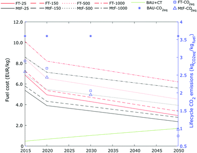
The cost of CO2 in the network was fixed to 25 € per t.20 However, this cost is related to the source of CO2 and the process required to purify the corresponding stream. According to the Global CCS Institute,20 the cost of CO2 avoided can vary from 17 to 166 € per t, depending on the source of CO2 and location of the facilities. To analyse further the impact of CO2 in the network, we performed a sensitivity analysis including costs across different ranges. Fig. 8 shows the results of the analysis for the FT and MtF routes for the scenarios NE and EI previously described. At costs of 25 € per t, the contribution of CO2 to the total cost of jet fuel is around 2%. As the cost of CO2 increases up to values in the range of direct air capture, the cost of fuel reached a minimum of 5.47 € per kgfuel in the MtF process with CO2 at 500 € per ton and a maximum close to 8.2 € per kgfuel in the FT process at 1000 € per ton.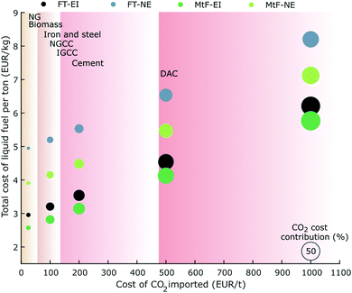 | ||
| Fig. 8 Jet fuel production cost for FT and MtF at different import costs of CO2. NE: no energy import to the network; EI: energy import allowed (natural gas and electricity from the grid). | ||
5.2 Electricity and hydrogen storage
Electricity and hydrogen storage are crucial to guarantee the operation of the system. In the results reported, values for a generic stationary system were selected for electricity storage at costs of 225 € per kW, and salt cavern and tanks considered for H2 storage at costs of 200 and 1200 € per kgH2, respectively. In terms of electricity, battery storage costs have changed rapidly over recent decades, with lithium-ion stationary systems expected to be the most cost-efficient technology in the long term.59 At present, lithium-ion utility systems cost approximately 600 € per kW, with an expected reduction up to 440 € per kW by 2030 and up to 250 € per kW by 2050,28,59,60 reaching similar values to those of pumped hydro (200 € per kW). Under these projections, four different scenarios are analysed to address stationary systems for electricity storage, considering low (225 € per kW), medium (500 € per kW), high (800 € per kW), and very high costs (2000 € per kW). In terms of H2 storage, salt caverns present the cheapest option with prices between 100 and 400 € per kg.47 However, this option is not available in all locations, requiring the need for compressed hydrogen storage at average costs of 1200 € per kg.47 Here, we also include low (100 € per kg), medium (200 € per kg), high (400 € per kg), and very high (1200 € per kg) cases for H2 storage. In these scenarios, neither electricity nor heat import were allowed, as otherwise the model would import energy resources to avoid storage, as previously reported. The carbon tax was also omitted.Fig. 9 shows the results for the scenarios described for MtF. Results for FT follow a similar pattern and are reported in the ESI.† In both routes, the cost of H2 storage has a minimal impact over the production cost of the fuel. When salt caverns are made available (100–400 € per kg), the network makes use of this technology, mainly using those located in the region of Valencia. As the costs of storage are raised to 1200 € per kgH2, meaning that compression of hydrogen is available in all the country, the model shows a more distributed arrangement at similar costs.
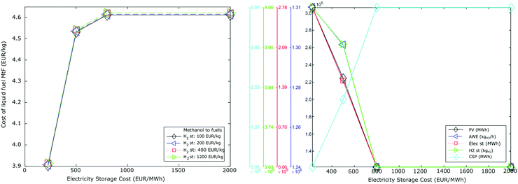 | ||
| Fig. 9 MtF fuel production costs and installed capacities of PV, CSP, AWE, storage of electricity and hydrogen for different storage costs. | ||
Electricity storage is required to guarantee the operation of all technologies during the night period. At the costs reported in Table 3, electricity production in the network for scenarios NE was 100 € per MW per h in PV and 170 € per MW per h in CSP, resulting in the deployment of PV. At costs of 500 € per kW for electricity storage the model starts to deploy an arrangement PV-Storage-CSP. Beyond costs of 800 € per kW for electricity storage, PV-CSP becomes the cheapest alternative, being deployed up to the level at which electricity storage is not required. In this scenario, electricity generation from CSP is 43% in FT and 46% in MtF. This also reduces the installed capacities of PV, AWE, and H2 storage, with an increase in fuel costs by 18% in both routes. The capacity factor of CSP is assumed at 0.45,52 with values up to 0.6 reported along with minimum loads of AWE of 10%. These technological improvements could further reduce production costs. While the use of other electrolysis technologies could also reduce the need for electricity storage, the current prices of these routes are still higher than the system of PV-AWE-Storage.30
5.3 Future performance of solar electricity and AWE
As PV, CSP, and AWE benefit from their large-scale deployment and decarbonisation of their manufacturing processes, a better performance is expected in both economic and environmental terms. These potential benefits are now analysed according to the capital costs and CO2 emissions reported in Section F of the ESI.†![[thin space (1/6-em)]](https://www.rsc.org/images/entities/char_2009.gif) 27,54,61 A scenario for 2015 is included to observe the improvements attained by these technologies over recent years.
27,54,61 A scenario for 2015 is included to observe the improvements attained by these technologies over recent years.
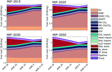
Fig. 10 shows the fuel cost and CO2 emissions for a system PV-Storage. A scenario based on PV-CSP is also reported in the ESI.† The costs reported include different costs of CO2, aiming to present production costs employing different sources, particularly DAC. As observed, a reduction in capital costs beyond 50% can be expected by 2050 compared to 2015, reaching minimum values of 2.50 € per kgfuel and life cycle emissions in the order of 1.0 kgCO2eq per kgfuel. These reductions are in agreement with values reported in the literature.11–13 However, our total costs are still higher than those reported given the need of a constant supply of H2. The minimum costs projected by 2050 consider CO2 prices around 25 € per tfuel. However, at this time it would also be expected that DAC would represent a primary source of CO2, as other point sources reduce their direct emissions. Using CO2 sources in the order of 500 € per ton by 2050 would result in similar production costs as being produced in 2020 with a different (and cheaper) point source of CO2. This shows that prices below 4.0 € per kgfuel will be difficult to attain in Spain as it seeks to develop a cleaner path toward aviation fuel. In terms of CO2 emissions, we can observe a significant reduction from 2.6–2.9 kgCO2eq per kgfuel for PV and 2.3–2.6 kgCO2eq per kgfuel for CSP in 2015 to 1.0 kgCO2eq per kgfuel for both PV and CSP by 2050. This is the result of a decarbonised energy mix used in the manufacture of the corresponding technologies.
5.4 Varying minimum operating load of AWE
The results presented assumed that AWE operates at a minimum load of 30%, creating the need for electricity storage when the import of energy is not allowed. However, different values for minimum loads of AWE have been reported and research efforts are being made to improve their operating performance. On this basis, we analysed the network at different minimum loads (30%, 20%, 10%, and 0%) for the years previously considered (2015, 2020, 2030, 2050). In this analysis, the cost of electricity storage was kept to 225 € per kW while H2 storage was defined at 100 € per kg and 1200 € per kg.Fig. 11 shows the economic breakdown for MtF. The results for FT follow the same trend and are reported in the ESI.† On average, the network reduced the deployment of electricity storage by 80 GW in FT and 100 GW in MtF for each 10% reduction of AWE minimum load. Similarly, an increase in AWE by 200 tH2 per h and 1100 kg of H2 storage was observed. As a result, changes in the electrolyser operation reflected a minimum impact for the total production costs of the fuels in 2015 and 2020. The further reduction costs defined for PV and AWE in 2030 and 2050 showed potential cost reductions up to 15% if electricity storage remains at 225 € per kW. The increase in cost of H2 storage from 100 to 1200 € per kgH2 represented an additional 0.1 € per kgfuel in FT and MtF. Average capacity factors for AWE were 54%, 46%, 39%, and 33% for minimum loads of 30%, 20%, 10%, and 0%, respectively. The production costs of hydrogen in the supply chain were between 11.3–11.5 € per tH2 in 2015, 7.5–8.0 € per tH2 in 2020, 6.5–7.0 € per tH2 in 2030, and 3.5–4.5 € per tH2 in 2050.
5.5 Discussion
Looking at the impact of CO2 in the total cost of the fuel, the use of point sources would represent the lowest production costs. In terms of storage, the results show that H2 storage has a minimal impact on the cost and design of the network, and the model primarily selects the storage in salt caverns. On the other hand, electricity storage presents a predominant role in the design of the network. Given its high cost (starting at 225 € per kW), the model deploys the minimum necessary storage volume required in order to guarantee the operation of AWE and the other technologies during the night periods. At a cost of 500 € per kW per h, the system PV-CSP reaches similar prices to those of the system PV-Storage (∼125 € per MW per h). At higher electricity storage costs, PV-CSP becomes the preferred choice of the model. Technology improvements could reduce production costs to as low as 2.2 € per kgfuel by 2050. However, by that time, it could also be expected to have highly decarbonised energy systems, rendering DAC as the main source of CO2. This would result in fuel production costs around 4.5 € per kgfuel, which are similar values estimated for 2020 using a PSC. Interestingly, the reduction of the minimum operating load of AWE shows small reductions in the cost of the fuel, as the reduction of electricity storage is offset by the increase in AWE. By 2050, the intermittent operation of AWE would present higher savings. These results, however, are characteristic of Spain and values could observe further reductions in different regions.6 Sustainable aviation fuels (SAF): Beyond solar-based jet fuel
6.1 Alternatives to solar-based jet fuel
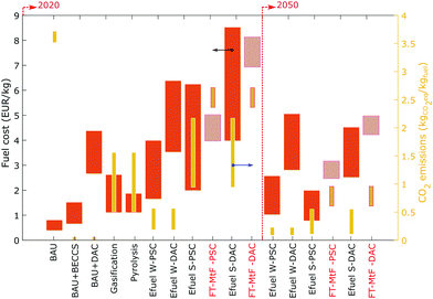
Different alternatives are available to produce SAF, including the coupling of fossil-based options with carbon capture and storage (CCS), biomass-based routes, and electrocatalytic-based options.9,62 As roadmaps to decarbonise the sector are presented, these technologies are also expected to be deployed at different times as their maturity develops. For instance, the higher TRL of synthetic biofuels would promote their deployment at present while E-fuels would be expected to be deployed from 2030 onwards.7,62 According to the ICAO,7 it would be physically possible to meet 100% of demand by 2050 with SAF, corresponding to a 63% reduction in emissions. However, this level of fuel production could only be achieved with large capital investments in SAF production infrastructure and substantial policy support. Fig. 12 shows the costs of different SAF technologies calculated from a wide range of values reported in the literature (Section G in the ESI†) including the costs obtained in our analysis. Here, we aim to present the benefits of our assessment to reduce cost uncertainties for the solar efuels using a regional assessment.Efuel costs reported show a variation between 1.7–6.2 € per kgfuel in 2020 and 0.8–2.5 € per kgfuel in 2050 for a point source of CO2 (PSC-25 € per tCO2). Here, the lower capacity factors for PV result in higher production costs compared to wind-based electricity. A detailed analysis of the potential for hybrid power (wind and solar power) combined with energy storage technology to reduce costs is beyond the scope of this work. In our assessment, the costs of solar E-fuels in Spain result in 4–5 € per kgfuel using a PSC (25 € per t) and 7–8 € per kgfuel using DAC for 2020, sitting in the upper half of the values reported in the literature. By 2050, fuel production in Spain varies from 2.5–3.3 € per kgfuel for PSC and 4.2–5.0 € per kgfuel for DAC. Here, our projections are above those calculated from the literature. The reason being the need to oversize PV, AWE, and their corresponding storage in order to guarantee a constant supply of hydrogen. These costs could be reduced if intermittent or a more flexible operation becomes possible for processes like FT or MtF.63 Similarly, guaranteeing the supply of electricity to the system could reduce costs. However, this supply should rely on renewable sources, given that import from the electricity mix in Spain would result in more polluting fuels than BAU. In this context, Fig. 12 also shows the fuel life cycle CO2 emissions of the alternatives proposed (right axis). Here, a significant reduction is observed when using E-fuels to around 1.0 kgCO2 per kgfuel by 2050. At this point, the CO2 embedded in the manufacture of solar panels would represent jet fuel with similar emissions to those of biofuels. Similarly, by 2050 the emissions embedded in PV are expected to have similar values to wind electricity. From the alternatives presented in Fig. 12, only offsetting would result in net-zero fuels. Using BECCS for this purpose, and assuming costs in the range of 15 and 250 € per tCO2, the cost of jet fuel would result in values between 0.6–1.5 € per kgfuel (BAU + BECCS). In the case of DAC, the costs of the fuel would represent 2.7–4.2 € per kgfuel (BAU + DAC). These values are in agreement with those reported by Becattini et al.13
6.2 The impact on flying
We finally present the impact that promoting SAF would have in a flight ticket. To this end, we use the U.S. Passenger Airline Cost Index (PACI),64 corresponding to the last quarter of 2019. A description of each of the elements and their cost contribution are given in the ESI.† If we assume an operating cost of 100 € (total flight ticket cost of 135 €), fuel represents 17.7 €. The cost of jet fuel during the last quarter of 2019 in the U.S. was 1.68 € per gallon,65 which represents a consumption of 10.5 gallons per passenger. If we now assume an airplane with a capacity of 154 passengers, the total amount of fuel used represents around 1600 gallons, corresponding to 1700 km. This is approximately the distance between the cities of Madrid and London. Note that this cost would represent a basic-economy ticket in a route where multiple airlines offer the service, i.e., a competitive market. As more expensive travel categories are selected, less offers exist for the desired travel, among many other factors, the ticket price would very likely be more expensive (up to 4 times for the economy class), resulting in a lower contribution from the fuel to the total cost of the flight ticket.Fig. 13 shows the total cost of a flight ticket per available seat km, which refers to the cost that a passenger pays per km travelled for the aircraft considered. According to the previous results, the values for FT/MtF refer to production costs in Spain. According to the data assumed for 2020 and with a cost of 25 € per tCO2, the flight ticket would increase by 127% in the FT route and 98% in MtF. If we consider a cost of 500 € per tCO2, the flight ticket would increase by 173% in FT and 142% in MtF, reaching costs of 0.22 € and 0.19, respectively. By 2050, the costs would present a reduction up to 0.18 € per seat km in FT and 0.14 € per seat km in MtF. This would represent increases by 80% in FT 40% in MtF compared to BAU, which would reach values around 0.10 € per seat km when a the carbon tax of 190 € per tCO2 defined by the IEA is included.55 This shows that carbon prices >500 € per tCO2 in 2050 would be required to make solar efuels economically attractive compared to BAU.
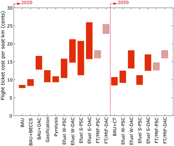 | ||
| Fig. 13 Total cost of flight ticket per available seat km. Costs represent a basic-economy ticket in a competitive route for a flight of 1700 km. | ||
7 Conclusions
We have assessed the production of jet fuel via Fischer–Tropsch and Methanol-to-Fuels using an RTN model based on solar radiation as an energy source in Spain. Our assessment reveals that investments of 42![[thin space (1/6-em)]](https://www.rsc.org/images/entities/char_2009.gif) 000 M€ in FT and 52
000 M€ in FT and 52![[thin space (1/6-em)]](https://www.rsc.org/images/entities/char_2009.gif) 000 M€ in MtF would be required to fulfill the current demand for jet fuel in Spain exclusively based on solar radiation, attaining life cycle CO2 reductions of 25%. These costs translate into fuels eight to ten times more expensive than the current oil-based scenario, representing costs of CO2 avoided of 4700 in FT and 2800 € per kgfuel in MtF. Given that the main costs drivers are PV, alkaline water electrolysis, and electricity storage, the import of electricity from the grid would reduce investment costs by ∼50%. However, this would come at the expense of increased emissions that surpass even those of conventional routes even when a carbon tax is imposed, reaching values of 7.2–8.2 kgCO2eq per kgfuel. The infrastructure requirements to meet Spains annual jet fuel demand are substantial. The deployment of PV would have to supply 15–40% more electricity than the total of 258 TW h consumed in Spain in 2017. Similarly, 5–6 MtH2 would be required, representing round 8% of current global H2 production. Electricity storage, another key element of the network, also shows a vast deployment, with capacities 400 times that of the London Gateway battery-storage system currently being developed. At storage costs around 500 € per kW, a deployment of CSP was observed, becoming the preferred choice over storage at costs above 800 € per kW. Further technological improvements could result in efuel costs as low as 2.2 € per kgfuel by 2050. However, by that time, the energy system may have significantly decarbonised, rendering DAC the main source of CO2. This would result in fuel production costs around 4.5 € per kgfuel, which are similar to the values estimated for 2020 using a PSC. In other regions, these values may be further reduced due to more favourable renewable resources.
000 M€ in MtF would be required to fulfill the current demand for jet fuel in Spain exclusively based on solar radiation, attaining life cycle CO2 reductions of 25%. These costs translate into fuels eight to ten times more expensive than the current oil-based scenario, representing costs of CO2 avoided of 4700 in FT and 2800 € per kgfuel in MtF. Given that the main costs drivers are PV, alkaline water electrolysis, and electricity storage, the import of electricity from the grid would reduce investment costs by ∼50%. However, this would come at the expense of increased emissions that surpass even those of conventional routes even when a carbon tax is imposed, reaching values of 7.2–8.2 kgCO2eq per kgfuel. The infrastructure requirements to meet Spains annual jet fuel demand are substantial. The deployment of PV would have to supply 15–40% more electricity than the total of 258 TW h consumed in Spain in 2017. Similarly, 5–6 MtH2 would be required, representing round 8% of current global H2 production. Electricity storage, another key element of the network, also shows a vast deployment, with capacities 400 times that of the London Gateway battery-storage system currently being developed. At storage costs around 500 € per kW, a deployment of CSP was observed, becoming the preferred choice over storage at costs above 800 € per kW. Further technological improvements could result in efuel costs as low as 2.2 € per kgfuel by 2050. However, by that time, the energy system may have significantly decarbonised, rendering DAC the main source of CO2. This would result in fuel production costs around 4.5 € per kgfuel, which are similar to the values estimated for 2020 using a PSC. In other regions, these values may be further reduced due to more favourable renewable resources.
Allowing the import of electricity in the network, up to the level in which the same emissions as the BAU option are attained, presents cost savings by 34% in 2020. A cleaner electricity mix than Spain could allow for further reductions. In both routes, increased rates of electricity are imported over time, reducing the cost of the fuel until the constraint on CO2 emissions is reached by the system. By 2050, the technological improvements and cost reductions of PV and AWE allow further cost and CO2 reductions. Ultimately, the impact of these process routes in the cost of a flight ticket in Spain would cause increase by 100–150% at present (2020) and 40–80% by 2050. These contributions could be considered as representative for an economy class, 1000 mile flight of a competitive flying route. As other factors come into play, such as business class, shorter flights, taxes, or less competitive routes, the fuel contribution to the cost of the flight ticket would be reduced.
The environmental benefits of deploying these process routes are evident, reducing life cycle emissions by ∼25% at present and expected reductions by 75% in 2050. From the behaviour observed, electricity storage is an element that is minimised under every scenario, and further integration of technologies able to reduce its deployment should be considered. A potential alternative is the coupling of solar PV with other electricity sources, such as wind, hydro, or nuclear. This could potentially reduce the amount of storage required to operate the electrolysers during the night period, resulting also in increased capacity factors and lower capital costs. Another alternative could be the use of electrolysers which are more easily able to operate intermittently, such as PEM or SOEC. The problem, however, is that the capital costs associatedwith these technologies are still higher than alkaline water electrilysis including for electricity storage. Overall, the costs associated with these routes should be carefully examined and compared against other alternatives, such as biomass gasification, pyrolysis, or carbon offsetting. Such a comparison would complement this analysis and further advance the understanding of different pathways towards net zero aviation fuel.
Nomenclature
![[Q with combining circumflex]](https://www.rsc.org/images/entities/i_char_0051_0302.gif) r,i′,i,t,k,l,tr
r,i′,i,t,k,l,tr
| Flow rate of resource r from cell i to i′ at time period t, k, l with transportation mode tr |
| CFj,t,k | Capacity factor of technology j at time period t in major time period k |
| i, i′ ∈ IMP | Spatial cells that can import |
| i, i′ | Spatial cells |
| r | Resources |
| r ∈ RD | Resources which need network design |
| r ∈ RI | Resources that can be imported |
| r ∈ RS | Resources which can be stored |
| r ∈ RF | Resources which can be transported |
| r | Resources |
| j | Technologies |
| j ∈ JS | Scalable technologies |
| j ∈ JUS | Non-scalable technologies |
| t | Daily time period |
| k | Seasonal time period |
| l | Investment period |
| m | Metric: CapEx, OpEx, CO2 emissions |
| tr | Transportation mode: truck, pipe |
| s | Capacity scale range of scalable technology |
| D min r,i,t,k,l | Minimum demand of r in cell i at time period t, major time period k and investment time period l (kg h−1) |
| Disti,i′ | Distance from cell i to cell i′ (km) |
| L TS j,s | Lower installed capacity bound for technology j within scale |
| μ j,r | Rate of r production/consumption per unit in technology j (kg or MW) |
| OBJWTm,l | Weight of metric m in investment period l |
| PIt | Hours assigned to each daily period t (hour) |
| PMk | Number of the seasonal period k (e.g. sample day of a season) |
| Q max r,tr | Maximum flow rate of resource r in transport mode tr (kg h−1) |
| Targetr,l | Target of final product resource r (e.g. jet fuel) (ton) |
| U TS j,s | Upper installed capacity bound for technology j within scale s |
| VIJj,i,m | Technology j metric m investment coefficient (M/unit capacity) |
| VISr,i,m | Storage technology for material r in cell i metric m investment coefficient |
| VPJj,m | Technology j metric m process coefficient |
| VTr,m | Flow value of r/m with truck transport |
| VIr,m | Import value of r/m |
| VYr,m | Value per metre of network of r/m |
| D r,i,t,k,l | Demand of r in cell i at time period t, major time period k and investment time period l (kg h−1) |
| IMr,i,t,k | Import of resource r in cell i period t major period k (MW h or kg h−1) |
| INVSr,i,l | Installed capacity of storage for material r in cell i at investment period l |
| INVTSj,i,l,s | Installed capacity of scalable technology j in cell i at investment period l at scale s |
| INVTj,i,l | Installed capacity of non scalable technology j in cell i at investment period l |
| N S r,i,l | Capacity of storage for material r in cell i at investment period l |
| N TS j,i,l,s | Capacity of scalable technology j in cell i at investment period l at scale s |
| N T j,i,l | Capacity of non scalable technology j in cell i at investment period l |
| P j,i,t,k,l | Production rate of technology j in cell i at periods t, k, l (MW or kg h−1) |
| RSr,i,t,k,l | Amount of resource r stored in cell i period t major period k at investment time period l (MW h or kg) |
| VMm,l | Total value of metric m in investment time period l |
| X i,j,l,s | Binary variable, 1 if there is installed technology j in cell i at investment period l within the scale level s, 0, otherwise |
| Y r,i,i′,l,tr | Binary variable, 1 if resource r between cell i and i′ can be transported via transportation method tr, 0, otherwise |
| AC | Objective function: annualised cost |
Conflicts of interest
There are no conflicts to declare.References
- UNFCCC, Paris Agreement, 2015.
- European Commission, Reducing emissions from aviation | Climate Action, 2017, https://ec.europa.eu/clima/policies/transport/aviation_en.
- IATA, IATA Industry Statistics Fact Sheet June 2020, 2020.
- Gatwick Airport, 2019 Performance report, 2019.
- Heathrow Airports Ltd, 2018.
- A. Monsalud, D. Ho and J. Rakas, Sustainable Cities Soc., 2015, 14, 414–424 CrossRef.
- ICAO, 2019 Environmental report aviation and environment, 2019, p. 3.
- S. S. Doliente, A. Narayan, J. F. D. Tapia, N. J. Samsatli, Y. Zhao and S. Samsatli, Front. Energy Res., 2020, 8, 110 CrossRef.
- Sustainable Aviation, Sustainable Aviation, 2016, pp. 1–85.
- International Energy Angency, Are aviation biofuels ready for take off? 2019, https://www.iea.org/commentaries/are-aviation-biofuels-ready-for-take-off.
- P. Schmidt, V. Batteiger, A. Roth, W. Weindorf and T. Raksha, Chem. Ing. Tech., 2018, 90(1–2), 127–140 CrossRef CAS.
- R. Terwel, J. Kerkhoven and F. W. Saris, Europhys. News, 2019, 50, 29–32 CrossRef CAS.
- V. Becattini, P. Gabrielli and M. Mazzotti, Ind. Eng. Chem. Res., 2020, 59(15), 7033–7045 CrossRef.
- A. Sánchez, M. Martín and Q. Zhang, Energy, 2021, 234, 121300 CrossRef.
- N. Sunny, N. Mac Dowell and N. Shah, Energy Environ. Sci., 2020, 13, 4204–4224 RSC.
- MITMA, Boletín estadístico online – Información estadística – Ministerio de Fomento, 2019, http://www.fomento.gob.es/BE/?nivel=2&orden=03000000, https://apps.fomento.gob.es/BoletinOnline2/?nivel=2&orden=36000000.
- AENA, Estadísticas – Aeropuertos Españoles – aena.es, 2018, http://www.aena.es/csee/Satellite?pagename=Estadisticas/Home.
- TheGlobalEconomy.com, Spain Jet fuel consumption – data, chart | TheGlobalEconomy.com, https://www.theglobaleconomy.com/Spain/jet_fuel_consumption/https://www.theglobaleconomy.com/Canada/jet_fuel_consumption/.
- S. Pfenninger and I. Staffell, Energy, 2016, 114, 1251–1265 CrossRef.
- L. Irlam, Global costs of carbon capture and storage 2017, 2017 Search PubMed.
- L. J. Müller, A. Kätelhön, S. Bringezu, S. McCoy, S. Suh, R. Edwards, V. Sick, S. Kaiser, R. Cuéllar-Franca, A. El Khamlichi, J. H. Lee, N. Von Der Assen and A. Bardow, Energy Environ. Sci., 2020, 13, 2979–2992 RSC.
- R. Frischknecht, N. Jungbluth, H. J. Althaus, G. Doka, R. Dones, T. Heck, S. Hellweg, R. Hischier, T. Nemecek, G. Rebitzer and M. Spielmann, Int. J. Life Cycle Assess., 2005, 10, 3–9 CrossRef CAS.
- Statista Research Department, Industry prices for electricity in Spain 2008–2018|Statista, 2020, https://www.statista.com/statistics/595813/electricity-industry-price-spain/, https://www.statista.com/statistics/595826/electricity-industry-price-italy/.
- R. C. Baliban, J. A. Elia and C. A. Floudas, Ind. Eng. Chem. Res., 2010, 49, 7343–7370 CrossRef CAS.
- R. K. Sinnott and G. Towler, Chemical Engineering Design, 2013 Search PubMed.
- A. Gonzalez-Garay and G. Guillen-Gosalbez, Chem. Eng. Res. Des., 2018, 137, 1711–1716 CrossRef.
- IRENA, 2020, 143.
- O. Schmidt, A. Gambhir, I. Staffell, A. Hawkes, J. Nelson and S. Few, Int. J. Hydrogen Energy, 2017, 42, 30470–30492 CrossRef CAS.
- C. Wulf, J. Linssen and P. Zapp, Hydrogen Supply Chain: Design, Deployment and Operation, Elsevier, 2018, pp. 309–345 Search PubMed.
- O. Schmidt, A. Hawkes, A. Gambhir and I. Staffell, Nat. Energy, 2017, 2, 17110 CrossRef.
- L. Kleiminger, PhD thesis, Imperial College London, 2015.
- K. M. Vanden Bussche and G. F. Froment, J. Catal., 1996, 161, 1–10 CrossRef CAS.
- W. L. Luyben, Ind. Eng. Chem. Res., 2010, 49, 6150–6163 CrossRef CAS.
- M. Menges and B. Kraushaar-Czarnetzki, Microporous Mesoporous Mater., 2012, 164, 172–181 CrossRef CAS.
- D. F. Rodríguez-Vallejo, G. Guillén-Gosálbez and B. Chachuat, ACS Sustainable Chem. Eng., 2020, 8(8), 3072–3081 CrossRef.
- R. J. Quann, L. A. Green, S. A. Tabak and F. J. Krambeck, Ind. Eng. Chem. Res., 1988, 27, 565–570 CrossRef CAS.
- D. Bibby, C. Chang, R. Howe and S. Yurchak, Studies in surface science and catalysis 36 Methane conversion, Elsevier, 1988 Search PubMed.
- A. D. Klerk, Energy Environ. Sci., 2011, 4, 1177–1205 RSC.
- P. M. Maitlis and A. de Klerk, Greener Fischer-Tropsch Processes for Fuels and Feedstocks, Wiley-VCH, Weinheim, Germany, 2013, p. 372 Search PubMed.
- J. E. Graciano, B. Chachuat and R. M. Alves, Ind. Eng. Chem. Res., 2018, 57, 9964–9976 CrossRef CAS.
- L. E. Øi, Energy Procedia, 2012, 23, 360–369 CrossRef.
- N. Jungbluth and M. Stucki, Life Cycle Inventories of Photovoltaics – ESU-services, ESU-Services Ltd, 2012, vol. 250 Search PubMed.
- T. Telsnig, PhD thesis, Universität Stuttgart, 2015.
- G. Wernet, C. Bauer, B. Steubing, J. Reinhard, E. Moreno-Ruiz, B. B. Weidema, R. Zah and W. Org, Int. J. Life Cycle Assess., 2016, 21, 1218–1230 CrossRef.
- U. Epa and C. for Corporate Climate Leadership, Emission Factors for Greenhouse Gas Inventories.
- W. Mallon, L. Buit, J. Van Wingerden, H. Lemmens and N. H. Eldrup, Energy Procedia, 2013, 2969–2980 CrossRef.
- J. Speirs, P. Balcombe, E. Johnson, J. Martin, N. Brandon and A. Hawkes, Energy Policy, 2018, 118, 291–297 CrossRef.
- W. A. Amos, Costs of Storing and Transporting Hydrogen, 1999 Search PubMed.
- IEA, IEA G20 Hydrogen report: Revised Assumptions, 2020.
- World Bank Group, State and Trends of Carbon Pricing 2019, 2019 Search PubMed.
- P. Wang, X. Deng, H. Zhou and S. Yu, J. Cleaner Prod., 2019, 209, 1494–1507 CrossRef.
- IRENA, International Renewable Energy Agency, 2018, pp. 1–86.
- IRENA, Future of solar photovoltaic, 2019, pp. 1–88.
- M. Pehl, A. Arvesen, F. Humpenöder, A. Popp, E. G. Hertwich and G. Luderer, Nat. Energy, 2017, 2, 939–945 CrossRef CAS.
- IEA (International Energy Agency), International Energy Agency, 2018, vol. 1, pp. 1–661.
- REE, The Spanish electricity system. 2020, 2021.
- InterGen, InterGen gains consent to build one of the world's largest battery projects in Essex | InterGen, https://www.intergen.com/news-insights/categories/news/intergen-gains-consent-to-build-one-of-the-worldslargestbattery-projects-in-essex/.
- C. Antonini, K. Treyer, A. Streb, M. van der Spek, C. Bauer and M. Mazzotti, Sustainable Energy Fuels, 2020, 4, 2967–2986 RSC.
- O. Schmidt, S. Melchior, A. Hawkes and I. Staffell, Joule, 2019, 3, 81–100 CrossRef.
- R. Fu, T. Remo and R. Margolis, 2018 U.S. Utility-Scale Photovoltaics-Plus-Energy Storage System Costs Benchmark, 2018.
- EU, EU Reference Scenario 2016, 2016, p. 27 Search PubMed.
- The Royal Society, Sustainable synthetic carbon based fuels for transport, 2019 Search PubMed.
- S. Van Bavel, S. Verma, E. Negro and M. Bracht, ACS Energy Lett., 2020, 5(8), 2597–2601 CrossRef CAS.
- Airlines for America, A4A Quarterly Passenger Airline Cost Index: U.S. Passenger Airlines, 2019.
- IndexMundi, Jet Fuel – Daily Price – Commodity Prices – Price Charts, Data, and News – IndexMundi, 2019, https://www.indexmundi.com/commodities/?commodity=jet-fuel&months=60https://www.indexmundi.com/commodities/?commodity=jet-fuel.
Footnote |
| † Electronic supplementary information (ESI) available: Details and results of the production of jet fuel from solar energy. See DOI: https://doi.org/10.1039/d1ee03437e |
| This journal is © The Royal Society of Chemistry 2022 |

