
The modulation acceptor of covalent organic frameworks: the optimization of intramolecular and interfacial charge transfer processes†
Ziang
Song
a,
Yujun
Xie
 a,
Xiaojuan
Song
a,
Jianing
Tang
a,
Jinfeng
Wang
*a,
Ben Zhong
Tang
*ac and
Zhen
Li
*abd
a,
Xiaojuan
Song
a,
Jianing
Tang
a,
Jinfeng
Wang
*a,
Ben Zhong
Tang
*ac and
Zhen
Li
*abd
aInstitute of Molecular Aggregation Science, Tianjin University, Tianjin 300072, China. E-mail: jinfeng.wang@tju.edu.cn
bJoint School of National University of Singapore and Tianjin University, International Campus of Tianjin University Binhai New City, Fuzhou, Fujian 350207, China
cSchool of Science and Engineering, Shenzhen Institute of Aggregate Science and Technology, The Chinese University of Hong Kong, Shenzhen, Guangdong 518172, China. E-mail: tangbenz@cuhk.edu.cn
dHubei Key Lab on Organic and Polymeric Opto-Electronic Materials, Department of Chemistry, Wuhan University, Wuhan, Hubei 430072, China. E-mail: lizhen@whu.edu.cn
First published on 12th October 2024
Abstract
Solar-driven water splitting for hydrogen evolution is one of the effective ways to alleviate environmental pollution and energy crisis. Covalent organic frameworks (COFs), as new platforms for solar-to-chemical energy, have drawn much attention owing to their pre-designable structures and tailor-made functions. Herein, three acceptor units containing different heteroatoms (O, S, and Se) were introduced and the corresponding photoactive COFs (Py-BO-COF, Py-BT-COF and Py-BSe-COF) with distinct donor–acceptor (D–A) structures were synthesized. Experimental and theoretical studies revealed that the different heteroatoms in acceptors affect the intramolecular and interfacial charge transfer and also significantly affect the valence state and deposition site of co-catalyst platinum. Py-BT-COF, with the best exciton separation ability and interfacial carrier migration ability, exhibits the highest hydrogen evolution rate (HER) up to 10.00 mmol g−1 h−1, which is 1.8 and 82 times than Py-BO-COF and Py-BSe-COF, demonstrating the effect of heteroatoms on carrier separation and migration of COFs and providing some guidance for the rational design of efficient photocatalysts with the D–A structure for hydrogen evolution.
 Jinfeng Wang | Jinfeng Wang received her PhD degree from Wuhan University in China under the guidance of Prof. Zhen Li in 2019 and then she joined Tianjin University (TJU). Her research interests mainly focus on the design and synthesis of new organic optoelectronic materials, including photocatalytic hydrogen evolution, organic pressure-responsive luminescent materials and dye-sensitized solar cells (DSSCs). She has published more than 10 papers, including Angew. Chem. Int. Ed., J. Mater. Chem. A, J. Mater. Chem. C, ACS Materials Letters and so on. |
Introduction
Since the industrial revolution, the exploitation and utilization of fossil energy have modernized human society. However, the expected depletion of fossil fuel reserves has triggered energy crisis and environmental problems such as climate warming, atmospheric pollution, geological disaster and nanoparticle pollution.1,2 Therefore, the development and utilization of renewable clean energy has become particularly important.3 Using sunlight to drive photocatalytic reactions to produce hydrogen is one of the most promising methods.4 Since Fujishima and Honda groundbreaking discovery in 1972 that water decomposition could be achieved on titanium dioxide electrodes under ultraviolet light, the design and synthesis of photocatalysts capable of using solar energy to drive water decomposition has aroused great research interest.5–11 Numerous inorganic photocatalysts, such as TiO2, MoS2, CdS, etc., have been investigated with good performance.12–20 However, their structural tenability, optimization of the band gaps and molecular orbital energy levels are constrained largely.21In recent years, organic photocatalysts have exhibited distinctive characteristics such as diverse structures, tunable band gaps and molecular orbital energy levels, and broad spectral response, offering them the ideal model for photocatalytic hydrogen evolution.22 Indeed, high-performance organic photocatalysts, such as organic sensitizers, linear conjugated polymers, conjugated microporous polymers, etc., have achieved great improvement in photocatalytic applications.23–25 For example, Zhang et al. synthesized a series of D–π–A–A-type CMPs, of which bare Py-BTDO-2 exhibited a high hydrogen evolution rate (HER) of 2.3 mmol h−1 with ascorbic acid as a sacrificial agent and methanol as a dispersant.26
Also, covalent organic frameworks (COFs), with long range ordered crystal structure, permanent pores, high specific surface area, excellent stability and molecular structure tenability, are considered to be very potential photocatalysts for hydrogen generation. In order to improve the photocatalytic performance of COFs, scientists have proposed a number of optimization strategies. Liu et al. constructed a Z-scheme heterojunction photocatalyst (MAC-FA1/S-COF) through the supramolecular interactions of S-COF and metal–organic ring (MAC-FA1).27 The HER of MAC-FA1/S-COF was 570 times than that of MAC-FA1 and 1356 times than that of S-COF, due to the more efficient electron–hole pair separation and migration of MAC-FA1/S-COF. Zhang et al. came up with an in situ defect strategy involving element doping by doping the Se atom in CTF-1, and the HER increased 8.2 times.28 In addition, construction of donor–acceptor (D–A) structures is another promising strategy for regulating the visible-light absorption range as well as the carrier separation/migration, which are the main factors that affect photocatalysis performance.29,30 However, the relationships between the structure and the property are still ambiguous, and the mechanism of reduction for hydrogen production is not clear. Therefore, the modulation acceptor unit of COFs for optimization of intramolecular and interfacial charge transfer is very essential.
In this work, partially based on our previous work on organic optoelectronic materials,31–45 benzoxadiazole, benzothiadiazole and benzoselenidazole containing different chalcogen atoms (O, S, and Se) were introduced as acceptors and then connected with pyrene via Schiff base reaction. Three photoactive COFs (Py-BO-COF, Py-BT-COF and Py-BSe-COF) were designed and synthesized, which displayed high crystallinity, specific surface areas, distinct pore structures and broad light absorption. The Py-BT-COF containing S atom exhibits a HER up to 10.00 mmol g−1 h−1, 1.8 and 82 times higher than those of Py-BO-COF and Py-BSe-COF, which exceeds the values of many COFs with a similar structural fragment. Further experimental and theoretical studies on the three COFs indicated that the introduction of heteroatoms in acceptors affected the intramolecular and interfacial charge transfer and also significantly affected the valence state and deposition site of the platinum co-catalyst. The big difference of the HER of Py-BT-COF compared with the other two COFs should be mainly due to the higher carrier separation and migration ability and the effective interfacial electron transfer from Py-BT-COF to Pt. This work reveals the effects of the acceptor units on the valence state and photo-deposited site of Pt, as well as the effects on carrier dynamics of COFs and interfacial charge transfer with Pt and COFs, providing guidance for the structural design of photoactive COFs and deeper understanding of the mechanism of photocatalytic hydrogen production.
Results and discussion
Synthesis and structural characterization of COFs
4,4′-(Benzo[c][1,2,5]oxadiazole-4,7-diyl)dibenzaldehyde (BO-CHO), 4,4′-(benzo[c][1,2,5]thiadiazole-4,7-diyl)dibenzaldehyde (BT-CHO) and 4,4′-(benzo[c][1,2,5]selenadiazole-4,7-diyl)dibenzaldehyde (BSe-CHO) were synthesized via the Suzuki–Miyaura coupling reaction (Schemes S1–S3, ESI†). The D–A type COFs (Py-BO-COF, Py-BT-COF and Py-BSe-COF) were synthesized by Schiff-based reactions in the mixtures of o-DCB/n-BuOH/0.6 M acetic acid solution (0.75/0.25/0.1 mL) at 120 °C for 3 days (Fig. 1a and Scheme S4, ESI†). Their structures were characterized in detail by various measurements. The crystallinity and crystal structure of COFs were characterized by powder X-ray diffraction (PXRD) combined with computational structural simulations. The experimental PXRD patterns showed that all of these three COFs displayed high crystallinity, indicating their long range orderly arrangement, which would benefit for photocatalytic water splitting (Fig. 1b–d).31,46–48 The observed PXRD pattern of Py-BT-COF displayed a strong peak at 2.7° and other weak peaks at 5.5°, 8.2°, 11.0° and 23.6°, which should be assigned to the (100), (200), (300), (400) and (001) planes, respectively. The other two COFs also showed similar diffraction peak positions, meaning that the three COFs showed a similar crystal arrangement. Compared with simulated PXRD patterns, the experimental PXRD patterns of COFs agreed well with the simulation from the eclipsed AA layer stacking model, with small residual values and profile differences (Py-BO-COF, Rwp = 5.26% and Rp = 2.69%; Py-BT-COF, Rwp = 3.71% and Rp = 2.52%; Py-BSe-COF, Rwp = 4.46% and Rp = 2.74%) (Fig. 1b–d and Fig. S4–S6, ESI†). In addition, the weak and broad diffraction peak located about 23° was assigned to (001) planes, which should be derived from interlayer π–π stacking. The diffraction peak displayed a slight decrease from 23.8° (Py-BO-COF) to 23.6° (Py-BT-COF), then to 23.5° (Py-BSe-COF), owing to the increase of the atomic radius of chalcogen atoms from O to Se.49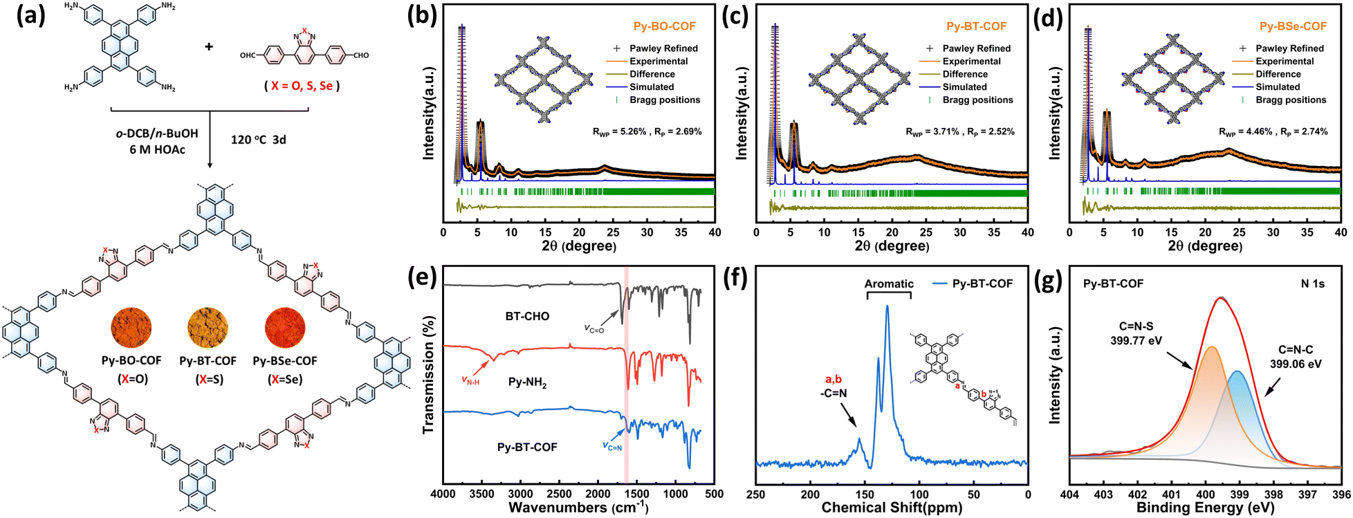 | ||
| Fig. 1 (a) Chemical structures and synthesis of Py-BO-COF, Py-BT-COF and Py-BSe-COF. PXRD patterns of Py-BO-COF (b), Py-BT-COF (c) and Py-BSe-COF (d). (e) FT-IR spectra of Py-BT-COF, BT-CHO and Py-NH2. (f) Solid state 13C CP/MAS NMR spectra of Py-BT-COF. (g) High resolution XPS spectra of N 1s for Py-BT-COF. | ||
Fourier transform infrared (FT-IR) spectra of the obtained COFs and their corresponding monomers were recorded as shown in Fig. 1e and Fig. S7 (ESI†). The stretching bands of amines in Py-NH2 (at 3344 cm−1 and 3432 cm−1) and the stretching bands of C![[double bond, length as m-dash]](https://www.rsc.org/images/entities/char_e001.gif) O in BO–CHO, BT–CHO and BSe–CHO (at 1700, 1689 and 1693 cm−1, respectively) disappeared, accompany with the appearance of a stretching band at 1623 cm−1, indicating the successful completion of the polymerization reaction and formation of CN linkages. The molecular structures of the three COFs were further confirmed by solid-state 13C cross-polarization magic-angle-spinning (CP/MAS) NMR spectroscopy (Fig. 1f and Fig. S8, ESI†). The signals were mainly located in the range of 100–175 ppm. The peaks in the range of 100–150 ppm were attributed to the carbons in the aromatic rings, and two signals located at 150–170 ppm were attributed to the C atom of the imine group in COFs, which further confirmed the existence of imine-linked structures. Moreover, X-ray photoelectron spectroscopy (XPS) was employed to evaluate the element compositions and chemical state. The XPS survey spectra showed that Py-BO-COF included the elements of C, N and O, Py-BT-COF included the elements of C, N and S, and Py-BSe-COF included the elements of C, N and Se (Fig. S9, ESI†). According to the high-resolution XPS spectra of N 1s, Py-BT-COF displayed two peaks at 399.06 and 399.77 eV, which were attributed to the carbon atoms of CN–C and CN–S moieties, respectively (Fig. 1g). Also, Py-BO-COF displayed two obvious peaks at 398.89 eV (CN–C) and 400.86 eV (CN–O), and Py-BSe-COF displayed two similar peaks at 399.08 (CN–C) and 399.47 eV (CN–Se) (Fig. S10, ESI†). The binding energies of imine linkage (CN–C) of Py-BO-COF, Py-BT-COF and Py-BSe-COF were similar (398.89, 399.06, and 399.08 eV, respectively), due to the same chemical environment of the N atom in the imine bond.50 However, the binding energy of CN–X (X = O, S, Se) decreased gradually (400.86, 399.77, and 399.47 eV, respectively), owing to the decrease of electronegativity from O to Se.51
O in BO–CHO, BT–CHO and BSe–CHO (at 1700, 1689 and 1693 cm−1, respectively) disappeared, accompany with the appearance of a stretching band at 1623 cm−1, indicating the successful completion of the polymerization reaction and formation of CN linkages. The molecular structures of the three COFs were further confirmed by solid-state 13C cross-polarization magic-angle-spinning (CP/MAS) NMR spectroscopy (Fig. 1f and Fig. S8, ESI†). The signals were mainly located in the range of 100–175 ppm. The peaks in the range of 100–150 ppm were attributed to the carbons in the aromatic rings, and two signals located at 150–170 ppm were attributed to the C atom of the imine group in COFs, which further confirmed the existence of imine-linked structures. Moreover, X-ray photoelectron spectroscopy (XPS) was employed to evaluate the element compositions and chemical state. The XPS survey spectra showed that Py-BO-COF included the elements of C, N and O, Py-BT-COF included the elements of C, N and S, and Py-BSe-COF included the elements of C, N and Se (Fig. S9, ESI†). According to the high-resolution XPS spectra of N 1s, Py-BT-COF displayed two peaks at 399.06 and 399.77 eV, which were attributed to the carbon atoms of CN–C and CN–S moieties, respectively (Fig. 1g). Also, Py-BO-COF displayed two obvious peaks at 398.89 eV (CN–C) and 400.86 eV (CN–O), and Py-BSe-COF displayed two similar peaks at 399.08 (CN–C) and 399.47 eV (CN–Se) (Fig. S10, ESI†). The binding energies of imine linkage (CN–C) of Py-BO-COF, Py-BT-COF and Py-BSe-COF were similar (398.89, 399.06, and 399.08 eV, respectively), due to the same chemical environment of the N atom in the imine bond.50 However, the binding energy of CN–X (X = O, S, Se) decreased gradually (400.86, 399.77, and 399.47 eV, respectively), owing to the decrease of electronegativity from O to Se.51
N2 adsorption–desorption measurements were performed at 77 K to study the permanent porosity and surface area of the COFs. As shown in Fig. 2a–c, all of three COFs showed typical type-IV isotherms and a steep step appeared at the range of p/p0 = 0.15–0.25, indicating that they were mesoporous materials. The Brunauer–Emmett–Teller (BET) surface areas were calculated to be 922 m2 g−1, 539 m2 g−1 and 596 m2 g−1 for Py-BO-COF, Py-BT-COF and Py-BSe-COF, respectively. Based on nonlocal density functional theory (NLDFT) calculation of the pore-size distribution and cylindrical pore model, the pore sizes were centered at 2.95 nm, 2.88 nm and 2.81 nm for Py-BO-COF, Py-BT-COF and Py-BSe-COF, respectively. Scanning electron microscopy (SEM) and transmission electron microscopy (TEM) were applied to investigate the morphology of the three COFs (Fig. 2d–i). The SEM images of the three COFs displayed a blocky-like morphology. TEM images revealed a highly ordered arrangement with clear lattice fringes of these three COFs.
 | ||
| Fig. 2 Nitrogen adsorption (filled circles)–desorption (open circles) isotherms of Py-BO-COF (a), Py-BT-COF (b) and Py-BSe-COF (c) at 77 K. Inset: The pore-size distribution profiles. SEM images of Py-BO-COF (d), Py-BT-COF (e) and Py-BSe-COF (f). TEM images of Py-BO-COF (g), Py-BT-COF (h) and Py-BSe-COF (i). Inset: Enlarged TEM images of the red square area and orange square area. | ||
In order to investigate the chemical stability of COFs, the powder samples were soaked in HCl (pH = 1), NaOH (pH = 14), tetrahydrofuran (THF) and ethyl alcohol (EtOH) at room temperature for 24 h. The PXRD patterns and FT-IR spectra suggested that the treated samples retained their crystallinity and molecular structure (Fig. S11–S13, ESI†). In addition, to evaluate the thermal stability of the three COFs, thermogravimetric analysis (TGA) was conducted in a nitrogen atmosphere with the temperature ranging from 40 to 800 °C. As shown in Fig. S14 (ESI†), all of the three COFs exhibited excellent thermal stability. Py-BT-COF with a thermal decomposition temperature (mass loss 5%) up to 506 °C showed the highest thermal stability. In contrast, the thermal decomposition temperatures of Py-BSe-COF and Py-BO-COF are 473 °C and 418 °C, respectively, slightly lower than that of Py-BT-COF.
Optoelectronic properties
UV-vis diffuse reflectance spectra (DRS) and Mott–Schottky (MS) plots were employed to research the light absorption capacity and energy band structure of COFs. As shown in Fig. 3a, all of these COFs displayed a wide absorption ranging from 350 nm to 600 nm, which suggested the better absorption capacity of visible light of COFs. The slightly expanded absorption range of Py-BO-COF and Py-BSe-COF compared to that of Py-BT-COF may be attributed to the increased crystallinity and the lower ionization potential of the selenium atom (Fig. S15, ESI†).52–54 According to Tauc plot curves, the optical band gaps were calculated to be 2.05 eV, 2.16 eV and 2.04 eV for Py-BO-COF, Py-BT-COF and Py-BSe-COF, respectively. The flat band potentials were calculated to be −1.04, −1.12 and −1.05 eV (vs. Ag/AgCl, pH = 6.8) for Py-BO-COF, Py-BT-COF and Py-BSe-COF by MS plots, respectively (Fig. S16, ESI†). The positive slope of the MS plots indicated that these COFs were n-type semiconductors. The flat band potential of n-type semiconductors is approximately equal to the conduction band potential, so the conduction band energies of these materials were calculated to be −0.44, −0.52 and −0.45 eV (vs. RHE, pH = 6.8), which are more negative than the proton reduction potential (0 eV, pH = 6.8), indicating that all COFs with enough driving force are suitable for photocatalytic hydrogen evolution from water (Fig. 3b). In addition, density functional theory (DFT) calculations were conducted to investigate the frontier molecular orbitals (Fig. S17, ESI†). The highest occupied molecular orbital (HOMO) was mainly centered on the pyrene unit, and the lowest unoccupied molecular orbital (LUMO) was centered on the acceptors such as benzoxadiazole, benzothiadiazole and benzoselenidazole units. The trend of calculation results of HOMO levels, LUMO levels and energy gaps are coincidence well with the results obtained from experiments.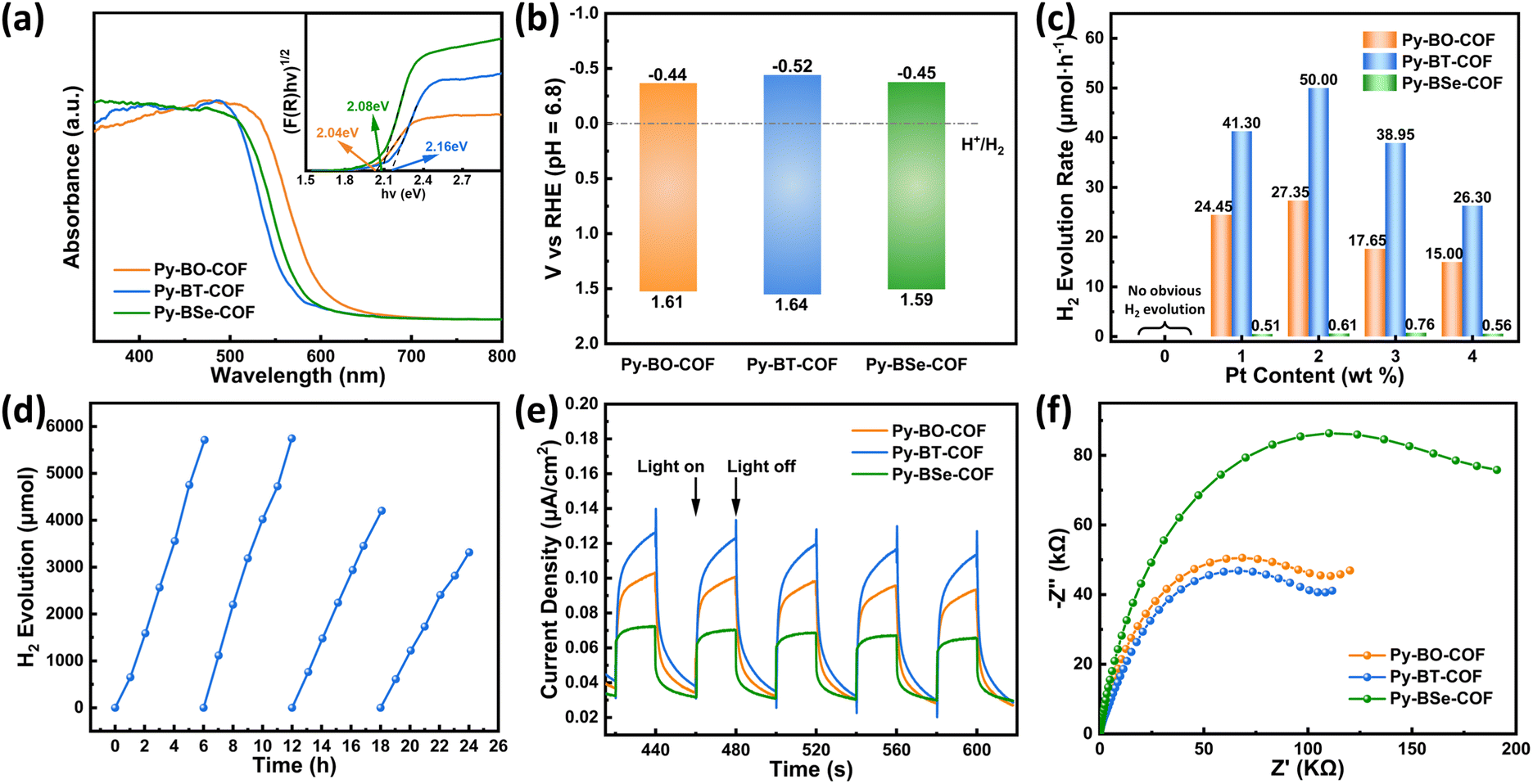 | ||
| Fig. 3 (a) UV-vis diffuse reflectance spectra of Py-BO-COF, Py-BT-COF and Py-BSe-COF. Inset: The corresponding Tauc plots. (b) Electronic band structures of COFs. (c) H2 evolution rates of COFs with different Pt loading amounts as the co-catalyst and ascorbic acid (0.1 M) as the sacrificial reagent, under simulated sunlight irradiation. (d) Recyclability test of Py-BT-COF with 2 wt% Pt as the co-catalyst and ascorbic acid (0.1 M) as the sacrificial reagent. (e) Transient photocurrent responses of COFs under visible light (λ > 420 nm) irradiation. (f) Electrochemical impedance spectroscopy (EIS) Nyquist plots of COFs. | ||
Photocatalytic properties of COFs
In order to study the relationship between the structure and photocatalytic activity, photocatalytic performances of three COFs were carried out under simulated sunlight (AM 1.5 G) irradiation in the presence of H2PtCl6·6H2O as the precursor of the co-catalyst and ascorbic acid (0.1 M) as the sacrificial reagent. Firstly, different contents of Pt (H2PtCl6) were applied to the reaction system for exploring the influence of Pt loading ratio to photocatalytic performance (Fig. 3c). If co-catalysts were not added, none of the three COFs can produce hydrogen by photocatalytic water splitting, indicating that the addition of the co-catalyst Pt is indispensable for the photocatalytic reaction. With the increase of Pt content from 1 wt% to 4 wt%, hydrogen production increased to the highest HER with the 2 wt% Pt content for Py-BT-COF and Py-BO-COF, and then decreased. The optimal Pt content for Py-BSe-COF was 3 wt%, which may be ascribed to the dispersed state of Pt on Py-BSe-COF. Furthermore, no matter how much Pt loaded, the HER of Py-BT-COF was always higher than that of Py-BO-COF and much higher than that of Py-BSe-COF. Py-BO-COF and Py-BSe-COF achieved their HERs as 27.35 μmol h−1 and 0.61 μmol h−1 with the 2 wt% Pt content, respectively. In comparison, Py-BT-COF displayed the highest photocatalytic performance with a HER of 50.00 μmol h−1 (10.00 mmol g−1 h−1), which were approximately 1.8 and 82 times higher than that of Py-BO-COF and Py-BSe-COF. High resolution transmission electron microscope (HR-TEM) was used to study the size distribution of photodeposited Pt of Py-BO-COF, Py-BT-COF and Py-BSe-COF with different Pt contents (1 wt%, 2 wt%, 3 wt% and 4 wt%) (Fig. S18–S20, ESI†). According to the results, Py-BO-COF and Py-BT-COF displayed the uniform dispersion of Pt nanoparticles (NPs) on the COFs, regardless of the Pt content. With the increased Pt content from 1 wt% to 4 wt%, the Pt NPs were distributed more densely, and their size mainly distributed in 2–4 nm. The numerous and densely distributed Pt NPs were not conducive to the light absorption of COFs, which might be the reason for the HER decrease with 3 wt% and 4 wt% of Pt contents.55 In addition, the obvious lattice fringes, about 0.23 nm, attributed to the facet of Pt (111) (Fig. S21 and S22, ESI†), were easily observed for these NPs on Py-BO-COF and Py-BT-COF. However, the NPs on Py-BSe-COF showed not well-defined clusters and distributed inconspicuous, and no lattice fringes were observed regardless of how many Pt contents are loaded, suggesting that the totally different state of Pt on Py-BSe-COF should possibly be another key factor for its extremely low HER under the same conditions. To further evaluate the performance of Py-BT-COF, the apparent quantum efficiency (AQE) was measured with a band-pass filter (365 nm, 420 nm, 500 nm), and the results were determined to be 0.73%, 1.26% and 0.16%, respectively (Fig. S23, ESI†). In order to research the stability of the three COFs, PXRD, SEM and TEM before and after photocatalysis were conducted (Fig. S18–S20, S24 and S25, ESI†). After the photocatalysis reaction, the intensity of diffraction peaks in PXRD patterns of the three COFs weakened, but the position of diffraction peaks did not change significantly, indicating that these COFs retain their original crystal structure. From the SEM and HR-TEM images, the morphology of the three COFs after photocatalysis was similar to original samples as blocky-like. Long-time photocatalytic cycle experiments of Py-BT-COF were carried out in ascorbic acid (0.1 M) with 2 wt% Pt loading for testing the photocatalytic cyclic stability (Fig. 3d). After four cycles (24 h), the hydrogen evolution rate decreased slightly, which should be ascribed to the hydrolysis of CN linkage in the acid (ascorbic acid solution) and the decrease of long-range ordering of Py-BT-COF. This deduction could be verified by the PXRD pattern and FT-IR spectrum after the long-term cycling experiments (Fig. S26, ESI†). The diffraction peaks of PXRD patterns showed a decrease in the intensity, after four cycles. And, the FT-IR spectrum showed that the stretching bands of N–H and CO increased.9
Mechanism
The photocatalytic hydrogen evolution process is essentially the same, which involves three basic steps: (i) absorption of sunlight and generation of electron–hole pairs; (ii) separation and migration of photogenerated carriers to the co-catalyst on the surface of photocatalysts; and (iii) surface reaction for reduction.17 Surprisingly, without the highest crystallinity, the largest BET surface area and the strongest light capture ability, Py-BT-COF exhibited the best photocatalytic hydrogen production performance of 50.00 μmol h−1. In contrast, Py-BSe-COF exhibited an extremely low HER (0.76 μmol h−1) with high crystallinity, a broader absorption range and a suitable conduction band. To investigate the underlying mechanism of different photocatalytic performances, a series of photoelectrical experiments and calculations were performed.The photocurrent response test was recorded by intermittent visible-light irradiation in order to study the generation and migration of photoinduced charges. As displayed in Fig. 3e, all of the three COFs demonstrated current values with light switching on. Py-BT-COF exhibited the highest photocurrent response intensity, suggesting the superior separation and mobility of photogenerated carriers. In addition, electrochemical impedance spectroscopy (EIS) was also applied to record the transport ability of photogenerated carriers (Fig. 3f). The EIS Nyquist plots exhibited that the semicircle diameter of Py-BT-COF was smaller than that of Py-BO-COF, much smaller than that of Py-BSe-COF, indicating the slightest resistance and the highest charge-transport ability of Py-BT-COF. Furthermore, the exciton effect has a decisive impact on the charge separation of COFs. Here, temperature-dependent photoluminescence tests were employed to investigate the exciton binding energy (Eb, Fig. 4a–c).56,57 Within the temperature range of our study, the PL intensity decreased with the increase of temperature, which illustrated thermal quenching of photoluminescence. The Eb value could be calculated using the Arrhenius equation: I(T) = I0/[1 + A![[thin space (1/6-em)]](https://www.rsc.org/images/entities/i_char_2009.gif) exp(−Eb/kBT)] (where I0 is the PL intensity at 0 K, T is the temperature, and kB is the Boltzmann constant). Accordingly, the Eb values of Py-BO-COF, Py-BT-COF and Py-BSe-COF were 94.9, 81.4 and 308.8 meV, respectively, demonstrating that excitons are more easily dissociated for Py-BT-COF with the smallest Eb value. For Py-BSe-COF, the Eb value was much higher than Py-BO-COF and Py-BT-COF. The difficulty of exciton separation may be one of the important factor for the poor photocatalytic performance.58
exp(−Eb/kBT)] (where I0 is the PL intensity at 0 K, T is the temperature, and kB is the Boltzmann constant). Accordingly, the Eb values of Py-BO-COF, Py-BT-COF and Py-BSe-COF were 94.9, 81.4 and 308.8 meV, respectively, demonstrating that excitons are more easily dissociated for Py-BT-COF with the smallest Eb value. For Py-BSe-COF, the Eb value was much higher than Py-BO-COF and Py-BT-COF. The difficulty of exciton separation may be one of the important factor for the poor photocatalytic performance.58
 | ||
| Fig. 4 Integrated PL intensity of Py-BO-COF (a), Py-BT-COF (b) and Py-BSe-COF (c) as a function of temperature. Inset: Temperature-dependent PL spectra. Time-correlated single photon counting (TCSPC) measured fluorescence decay profiles of Py-BO-COF (d), Py-BT-COF (e) and Py-BSe-COF (f) before and after Pt photodeposition. Inset: Steady-state photoluminescence (PL) spectra of COFs before and after Pt photodeposition. | ||
In order to illustrate the effect of Pt on the electron–hole separation efficiency of COFs, the steady-state fluorescence spectra and time-resolved photoluminescence (PL) spectra of COFs before and after loading Pt were recorded (Fig. 4d–f). The PL intensity of all three COFs decreased significantly after photodeposition of Pt, indicating that the electron–hole recombination was inhibited. Py-BT-COF and Py-BO-COF displayed the similar PL lifetime, but after loading Pt, the lifetime of Py-BT-COF@Pt decreased significantly (ΔτAMP = 0.28 ns), which is higher than that of Py-BO-COF@Pt (ΔτAMP = 0.14 ns). The most obvious lifetime attenuation meant that more photogenerated carriers were transferred to Pt to participate in the proton reduction reaction in the photocatalytic process.58 However, Py-BSe-COF showed the shortest PL lifetime of about 0.35 ns and without a significant change after loading Pt (ΔτAMP = 0.01 ns), illustrating its inefficient carrier transfer to the Pt co-catalyst.
Pt, as the co-catalyst, is often prepared by photodeposition of precursor ions (PtCl62−). HR-TEM images have revealed differences in the states of the photodeposits on the three COFs with the 2 wt% Pt content (Fig. S18–S22, ESI†). Theoretical calculations and XPS test were conducted to further discuss the valence state, the deposition site of photodeposited Pt, and their effect on the photocatalytic activity of the three COFs. Electron and hole distributions of these structural fragments were constructed by Multiwfn and visual molecular dynamics (VMD) (Fig. S27, ESI†).55,59,60 The electron separation and hole separation were evaluated by the S and D values, where S is the overlap integral of the electron–hole distribution and D means the distance between the centroids of holes and electrons. The D values of Py-BO-COF, Py-BT-COF and Py-BSe-COF were calculated as 3.005, 3.460 and 3.653 Å, respectively, indicating that the degree of electron–hole separation gradually increased. At the same time, it was also observed that the electrons were mainly distributed on the acceptors and some spread to the N(CN–C) for Py-BO-COF and Py-BT-COF. However, almost no electrons are distributed on N(CN–C) of Py-BSe-COF. The difference of the electron distribution may affect the deposition site of Pt. Furthermore, the state of Pt on the three COFs was investigated by XPS spectra of Pt 4f. For Py-BO-COF and Py-BT-COF, the proportion of Pt(0) was higher than Pt(II), and Pt existed mainly as Pt(0). However, for Py-BSe-COF, the proportion of Pt(II) was higher than Pt(0), and Pt existed mainly as Pt(II) (Fig. S28, ESI†). The results were consistent with the phenomena observed in TEM patterns that Py-BO-COF and Py-BT-COF showed obvious Pt nanoparticles after photocatalysis, while Py-BSe-COF showed inconspicuous larger and no well-defined clusters (Fig. S18–S20, ESI†). Compared with Pt(0), Pt(II) was unfavourable to proton reduction, possibly another key factor that Py-BSe-COF displayed the extremely low HER under the same conditions.61
The deposition site of Pt also plays an important role in photocatalytic hydrogen production. As shown in Fig. 5a–f, the binding energy changed after photodeposition, indicating that there was an interaction between COFs and sediments. New peaks (green line) were observed in the XPS spectra after deposition of Pt (Fig. 5a–c), which were attributed to the coordination bonds between O/S/Se and Pt.62 For Py-BT-COF, the binding energy of S 2p1/2, 2P3/2 and N(CN–C) did not change significantly after deposition, while the binding energy of N(CN–S) increased by 0.08 eV, indicating that the electron cloud density of N(CN–S) decreased and electron transfer occurred. Combined with the significant charge transfer between Py-BT-COF and Pt analyzed above, the main deposition site of Pt(0) was supposed to be located on N(CN–S), which could also be confirmed by previous literature studies63,64 For Py-BO-COF, the binding energies of O(CN–O) and N(CN–O) decreased, while the binding energy of N(CN–C) increased by 0.08 eV. Considering the distance of the induction effect and the study on the effect of the size of Pt(0) on electron transfer, the main deposition site of Pt(0) was considered to be located on N(CN–C).51 For Py-BSe-COF, the binding energy of Se 3P3/2, 3P5/2 decreased significantly, and the binding energies of N(CN–C) and N(C = N–Se) increased significantly, indicating a stronger interaction between platinum deposits and Py-BSe-COF, which may be due to the Pt(II)-form deposits. Additionally, electron–hole analysis discussed above (Fig. S27, ESI†) demonstrated that almost no electrons distribute on the N(CN–C) of the Py-BSe-COF fragment, which is unfavourable for the reduction of platinum precursor ions on N(CN–C). So, the main deposition site of the few remaining Pt(0) is speculated to located on N(CN–Se). Therefore, only when the Pt deposition site and the charge accumulation site are in the same position, and abundant platinum is present in the form of Pt(0), the photocatalytic performance will be better. Based on the above analysis, the electron transport path of photocatalytic hydrogen production was postulated as shown in Fig. 5g–i.
 | ||
| Fig. 5 (a) High resolution XPS spectra of S 2p for Py-BT-COF before and after photocatalysis. (b) High resolution XPS spectra of O 1s for Py-BO-COF before and after photocatalysis. (c) High resolution XPS spectra of Se 3d for Py-BSe-COF before and after photocatalysis. High resolution XPS spectra of N 1s for (d) Py-BT-COF, (e) Py-BO-COF and (f) Py-BSe-COF before and after photocatalysis. The photocatalytic hydrogen production mechanism diagram of (g) Py-BT-COF, (h) Py-BO-COF and (i) Py-BSe-COF. Red dotted line: the direction of photogenic electron migration. | ||
Conclusion of the discussion above, the process of carrier separation and migration (intramolecular and interfacial charge transfer) is analysed in detail. Py-BT-COF exhibits the lowest exciton binding energy (Eb) and the lowest charge-transfer resistance, which allow it to produce more photogenerated carriers and migrate to the surface. Meanwhile, the Pt co-catalyst, dispersed on the Py-BT-COF, exists mainly as Pt(0), and it’s deposition site is consistent with the accumulation of photogenerated electrons in the Py-BT-COF, which allow the photogenerated carriers to efficiently transfer from the Py-BT-COF to Pt(0) to participate in proton reduction reaction and make the Py-BT-COF achieve optimal photocatalytic performance. Py-BO-COF has similar Eb and charge-transfer resistance to Py-BT-COF, but the deposition site of Pt(0) is different from the accumulation of photogenerated electrons in Py-BO-COF, which results in a decrease in carriers transfer efficiency from the Py-BO-COF to Pt(0) and make the HER of Py-BO-COF lower than Py-BT-COF. As for Py-BSe-COF, its own photogenerated carriers separation and migration ability is inferior, and the Pt exists mainly as Pt(II), unfavourable to proton reduction, which result in the much lower HER of Py-BSe-COF than Py-BT-COF and Py-BO-COF.
Conclusions
In summary, three photoactive COFs with distinct donor–acceptor (D–A) structures were synthesized. The modulation of acceptor units by introducing different heteroatoms (O, S, and Se) could optimize the intramolecular and interfacial charge transfer efficiently. Although the three COFs have a similar D–A structure, they displayed significant differences on the electron–hole distribution, exciton separation ability and the charge transfer process. Py-BT-COF, with strong exciton separation ability and more efficient intramolecular and interfacial charge transfer, displayed the best photocatalytic performance. The difficulty of exciton separation and the Pt state of the Py-BSe-COF led to an inefficient charge separation and transfer, resulting in its poor photoactivity. Py-BT-COF exhibited the highest evolution rate of up to 10.00 mmol g−1 h−1, about 1.8 and 82 times higher than those of Py-BO-COF and Py-BSe-COF. Our work clarified the effects of intramolecular charge transfer and effective interfacial electron transfer on photocatalytic performance and provided some guidance for the rational design of efficient photocatalysts with D–A structures for hydrogen evolution.Data availability
The data supporting this article have been included as part of the ESI.†Conflicts of interest
There are no conflicts to declare.Acknowledgements
We are grateful to the National Natural Science Foundation of China (No. 22105143), the starting Grants of Tianjin University and the Tianjin Government for financial support. Thanks to the AIE Institute (https://www.aietech.org.cn) for providing some technical assistance.Notes and references
- F. Barbir, T. N. Veziroğlu and H. J. Plass, Int. J. Hydrogen Energy, 1990, 15, 739–749 CrossRef CAS.
- L. F. Silva, M. Santosh, M. Schindler, J. Gasparotto, G. L. Dotto, M. L. Oliveira and M. F. Hochella, Gondwana Res., 2021, 92, 184–201 CrossRef CAS.
- G. Nicoletti, N. Arcuri, G. Nicoletti and R. Bruno, Energy Convers. Manage., 2015, 89, 205–213 CrossRef.
- J. Qi, W. Zhang and R. Cao, Adv. Energy Mater., 2018, 8, 1701620 CrossRef.
- A. Fujishima and K. Honda, Nature, 1972, 238, 37–38 CrossRef CAS PubMed.
- X. Tao, Y. Zhao, S. Wang, C. Li and R. Li, Chem. Soc. Rev., 2022, 51, 3561–3608 RSC.
- Y. Shi, A. Yang, C. Cao and B. Zhao, Coord. Chem. Rev., 2019, 390, 50–75 CrossRef CAS.
- M. Mohsin, I. A. Bhatti, M. Zeshan, M. Yousaf and M. Iqbal, FlatChem, 2023, 42, 100547 CrossRef CAS.
- S. Zhu, Z. Zhang, Z. Li and X. Liu, Mater. Chem. Front., 2024, 8, 1513–1535 RSC.
- G. B. Bodedla, M. Imran, J. Zhao, X. Zhu and W. Wong, Aggregate, 2023, 4, e364 CrossRef CAS.
- Y. Huang, Y. Wang, S. Chen, J. Gao, Y. Wang, Y. Zhang and P. Deng, Aggregate, 2023, 4, e335 CrossRef CAS.
- Z. Luo, X. Han, Z. Ma, B. Zhang, X. Zheng, Y. Liu, M. Gao, G. Zhao, Y. Lin, H. Pan and W. Sun, Angew. Chem., Int. Ed., 2024, 63, e202406728 CrossRef CAS PubMed.
- P. You, D. Chen, X. Liu, C. Zhang, A. Selloni and S. Meng, Nat. Mater., 2024, 23, 1100–1106 CrossRef CAS PubMed.
- J. Li, Y. Wang, H. Song, Y. Guo, S. Hu, H. Zheng, S. Zhang, X. Li, Q. Gao, C. Li, Z. Zhu and Y. Wang, Adv. Compos. Hybrid Mater., 2023, 6, 83 CrossRef CAS.
- Y. Li, Z. Jin and N. Tsubaki, J. Mater. Chem. C, 2022, 10, 18213–18225 RSC.
- Z. Liu, Y. Li and Z. Jin, J. Mater. Chem. C, 2023, 11, 9327–9340 RSC.
- Z. Zhang, Q. Li, X. Qiao, D. Hou and D. Li, Chin. J. Catal., 2019, 40, 371–379 CrossRef CAS.
- C. Bie, B. Zhu, L. Wang, H. Yu, C. Jiang, T. Chen and J. Yu, Angew. Chem., Int. Ed., 2022, 61, e202212045 CrossRef CAS PubMed.
- T. Wang and Z. Jin, J. Mater. Chem. C, 2023, 11, 13957–13970 RSC.
- T. Wang, Z. Yin, Y. Guo, F. Bai, J. Chen, W. Dong, J. Liu, Z. Hu, L. Chen, Y. Li and B. Su, CCS Chem., 2023, 5, 1773–1788 CrossRef CAS.
- G. Wang, S. Li, C. Yan, F. Zhu, Q. Lin, K. Xie, Y. Geng and Y. Dong, J. Mater. Chem. A, 2020, 8, 6957–6983 RSC.
- C. Lin, X. Liu, B. Yu, C. Han, L. Gong, C. Wang, Y. Gao, Y. Bian and J. Jiang, ACS Appl. Mater. Interfaces, 2021, 13, 27041–27048 CrossRef CAS PubMed.
- X. Hai, L. Fang, M. Xiong, X. Zhou, S. Wang, H. Sun, C. Su and H. Chen, ACS Nano, 2023, 17, 20570–20579 CrossRef CAS PubMed.
- J. Xu, Z. Jiao, Z. Li, Y. Tian, B. Liu, G. Yue and Y. Tian, Chem. Eng. J., 2023, 473, 145359 CrossRef CAS.
- C. Han, S. Xiang, M. Ge, P. Xie, C. Zhang and J. Jiang, Small, 2022, 18, 2202072 CrossRef CAS PubMed.
- C. Han, L. Hu, S. Jin, J. Ma, J. Jiang and C. Zhang, ACS Appl. Mater. Interfaces, 2023, 15, 36404–36411 CrossRef CAS PubMed.
- X. Li, Z. Liang, Y. Zhou, J. Huang, X. Wang, L. Xiao and J. Liu, Aggregate, 2024, 5, e442 CrossRef CAS.
- M. Chen, J. Xiong, X. Li, Q. Shi, T. Li, Y. Feng and B. Zhang, Sci. China: Chem., 2023, 66, 2363–2370 CrossRef CAS.
- F. Liu, Y. He, X. Liu, Z. Wang, H. Liu, X. Zhu, C. Hou, Y. Weng, Q. Zhang and Y. Chen, ACS Catal., 2022, 12, 9494–9502 CrossRef CAS.
- X. Bai, Z. Yu, Y. Li, T. Zhang, D. Zhang, J. Wang, J. Pei and D. Zhao, Chin. J. Polym. Sci., 2023, 41, 1584–1590 CrossRef CAS.
- M. Wang, Z. Wang, M. Shan, J. Wang, Z. Qiu, J. Song and Z. Li, Chem. Mater., 2023, 35, 5368–5377 CrossRef CAS.
- Z. Wang, M. Wang, J. Song, J. Wu and Z. Li, Mater. Chem. Front., 2023, 7, 2651–2660 RSC.
- S. Liu, P. Lin, M. Wu, Z. Lan, H. Zhuzhang, M. Han, Y. Fan, X. Chen, X. Wang, Q. Li and Z. Li, Appl. Catal., B, 2022, 309, 121257 CrossRef CAS.
- S. Liu, Q. Chen, Y. Chen, P. Lin, H. Zhuzhang, M. Han, Z. Lan, X. Chen, X. Wang, Q. Li and Z. Li, J. Mater. Chem. A, 2023, 11, 14682–14689 RSC.
- S. Li, J. Gu, J. Wang, W. Yuan, G. Ye, L. Yuan, Q. Liao, L. Wang, Z. Li and Q. Li, Adv. Sci., 2024, 11, 2402846 CrossRef CAS PubMed.
- Y. Wang, W. Zhang, J. Yang, Y. Gong, J. Zhang, M. Fang, Q. Yang and Z. Li, Matter, 2022, 5, 4467–4479 CrossRef CAS.
- Y. Chen, A. Li, X. Li, L. Tu, Y. Xie, S. Xu and Z. Li, Adv. Mater., 2023, 35, 2211917 CrossRef CAS PubMed.
- Y. Fan, Q. Li and Z. Li, Sci. China: Chem., 2023, 66, 2930–2940 CrossRef CAS.
- Y. Gao, J. Liu, Q. Liao, S. Li, Q. Li and Z. Li, Natl. Sci. Rev., 2023, 10, nwad239 CrossRef CAS PubMed.
- A. Huang, Q. Li and Z. Li, Chin. J. Chem., 2022, 40, 2356–2370 CrossRef CAS.
- Q. Li and Z. Li, Acc. Chem. Res., 2020, 53, 962–973 CrossRef CAS PubMed.
- L. Tu, Y. Fan, C. Bi, L. Xiao, Y. Li, A. Li, W. Che, Y. Xie, Y. Zhang, S. Xu, W. Xu, Q. Li and Z. Li, Sci. China: Chem., 2023, 66, 816–825 CAS.
- J. Wang, A. Li and Z. Li, Prog. Chem., 2022, 34, 487–498 CAS.
- Y. Yang, J. Wang, J. Yang, L. Tong, D. Li, Y. Yang, M. Fang and Z. Li, Angew. Chem., Int. Ed., 2023, 62, e202218994 CrossRef CAS PubMed.
- A. Huang, Y. Fan, K. Wang, Z. Wang, X. Wang, K. Chang, Y. Gao, M. Chen, Q. Li and Z. Li, Adv. Mater., 2023, 35, 2209166 CrossRef CAS PubMed.
- M. Liu, Q. Huang, S. Wang, Z. Li, B. Li, S. Jin and B. Tian, Angew. Chem., Int. Ed., 2018, 57, 11968–11972 CrossRef CAS PubMed.
- S. Wang, F. He, Y. Lu, Y. Wu, Y. Zhang, P. Dong, X. Liu, C. Zhao, S. Wang, D. Wang, J. Zhang and S. Wang, J. Colloid Interface Sci., 2024, 654, 317–326 CrossRef CAS PubMed.
- J. Pei, Chin. J. Polym. Sci., 2023, 41, 1498–1500 CrossRef CAS.
- W. Chen, L. Wang, D. Mo, F. He, Z. Wen, X. Wu, H. Xu and L. Chen, Angew. Chem., Int. Ed., 2020, 59, 16902–16909 CrossRef CAS PubMed.
- D. Yan, Z. Wang, P. Chen, Y. Chen and Z. Zhang, Angew. Chem., Int. Ed., 2021, 60, 6055–6060 CrossRef CAS PubMed.
- J. Li, J. Jia, J. Suo, C. Li, Z. Wang, H. Li, V. Valtchev, S. Qiu, X. Liu and Q. Fang, J. Mater. Chem. A, 2023, 11, 18349–18355 RSC.
- N. Keller, D. Bessinger, S. Reuter, M. Calik, L. Ascherl, F. C. Hanusch, F. Auras and T. Bein, J. Am. Chem. Soc., 2017, 139, 8194–8199 CrossRef CAS PubMed.
- Y. Wu, A. Ji, H. Lou, R. Song, Z. Cheng, W. Chen and C. Qu, Adv. Ther., 2023, 6, 2300159 CrossRef CAS.
- Abdullah, E. Kim, M. S. Akhtar, H. Shin, S. Ameen and M. K. Nazeeruddin, ACS Appl. Energy Mater., 2021, 4, 312–321 CrossRef CAS.
- Y. Li, L. Yang, H. He, L. Sun, H. Wang, X. Fang, Y. Zhao, D. Zheng, Y. Qi, Z. Li and W. Deng, Nat. Commun., 2022, 13, 1355 CrossRef CAS PubMed.
- C. Yang, Z. Zhang, J. Li, Y. Hou, Q. Zhang, Z. Li, H. Yue and X. Liu, Green Chem., 2024, 26, 2605–2612 RSC.
- G. Fu, D. Yang, S. Xu, S. Li, Y. Zhao, H. Yang, D. Wu, P. S. Petkov, Z. Lan, X. Wang and T. Zhang, J. Am. Chem. Soc., 2024, 146, 1318–1325 CrossRef CAS PubMed.
- X. Li, W. Bi, L. Zhang, S. Tao, W. Chu, Q. Zhang, Y. Luo, C. Wu and Y. Xie, Adv. Mater., 2016, 28, 2427–2431 CrossRef CAS PubMed.
- T. Lu and F. Chen, J. Comput. Chem., 2012, 33, 580–592 CrossRef CAS PubMed.
- W. Humphrey, A. Dalke and K. Schulten, J. Mol. Graphics, 1996, 14, 33–38 CrossRef CAS PubMed.
- F. Zhang, J. Chen, X. Zhang, W. Gao, R. Jin, N. Guan and Y. Li, Langmuir, 2004, 20, 9329–9334 CrossRef CAS PubMed.
- W. A. Spieker, J. Liu, J. T. Miller, A. J. Kropf and J. R. Regalbuto, Appl. Catal., A, 2002, 232, 219–235 CrossRef CAS.
- Z. Zhao, Y. Zheng, C. Wang, S. Zhang, J. Song, Y. Li, S. Ma, P. Cheng, Z. Zhang and Y. Chen, ACS Catal., 2021, 11, 2098–2107 CrossRef CAS.
- J. Chen, Y. Wu, W. Zhang, J. Zhang, L. Wang, M. Zhou, F. Fan, X. Wu and H. Xu, Adv. Mater., 2024, 36, 2305313 CrossRef PubMed.
Footnote |
| † Electronic supplementary information (ESI) available. See DOI: https://doi.org/10.1039/d4tc03254c |
| This journal is © The Royal Society of Chemistry 2024 |