
Theranostic fluorescent silica encapsulated magnetic nanoassemblies for in vitro MRI imaging and hyperthermia†
Sunil Kumara,
Amita Davereybc,
Vahid Khalilzad-Sharghid,
Niroj K. Sahub,
Srivatsan Kidambic,
Shadi F. Othmand and
Dhirendra Bahadur*b
aDepartment of Chemical Engineering, Indian Institute of Technology, Mumbai-400076, India
bDepartment of Metallurgical Engineering and Materials Science, Indian Institute of Technology, Mumbai-400076, India. E-mail: dhirenb@iitb.ac.in; Fax: +91 22 2576 3480; Tel: +91 22 25767632
cDepartment of Chemical and Bimolecular Engineering, University of Nebraska, Lincoln, NE-68588, USA
dDepartment of Biological Systems Engineering, University of Nebraska, Lincoln, NE-68588, USA
First published on 5th June 2015
Abstract
This article reports the synthesis of manganese ferrite nano-assemblies (MNAs) encapsulated with fluorescent silica shell and demonstrates their applicability for magnetic hyperthermia, optical and T2 contrast MRI imaging with HeLa cancer cells. The MNAs were encapsulated by a double layer of silica shell through a two-step sol–gel process. The inner silica shell contains rhodamine-B isothiocyanate (RITC) dye, whereas the outer silica layer is without RITC-dye, helps to prevent photo-bleaching and increase photo-luminance. MNAs@Dye–SiO2@SiO2 exhibited a high magnetization of 90.43 emu g−1 with a remarkably high r2 value of 598 ± 2 mM−1 s−1 (Mn + Fe). The cellular uptake of MNAs@Dye–SiO2@SiO2 was observed by the presence of fluorescent red granulated spots in the cytoplasm of HeLa cells, confirming its efficacy for optical imaging. High transverse relaxivities r2 (darkening effect) were observed in HeLa cells incubated with MNAs@Dye–SiO2@SiO2 in comparison to HeLa cells without particles. An 80–85% cell death was achieved on induction of magnetic hyperthermia with HeLa cells at the lowest Hf factor value (3.3 × 10⁹ A m−1 s−1). Our results show MNAs@Dye–SiO2@SiO2 as a novel multifunctional theranostic nanoprobe, which can realize its applicability for diagnostic and real time monitoring the efficacy of ongoing cancer therapy.
1. Introduction
Recent advances in nanotechnology have made significant progress in the treatment of various diseases including cancer. A potential theranostic nanosystem can be evaluated based on the ability to monitor and deliver the therapeutic molecules at the specific site of a tumour. Therefore, the capability of imaging and targeted therapy at specific sites are the two important criteria for cancer theranostics.1 In the past few years, several nanosystems have been proposed as potential theranostics for cancer.1 Amongst these, super-paramagnetic iron oxide nanoparticles (SPIONs) or their derivates have emerged as a better option due to their unique properties of magnetic manipulation, applicability as T2 contrast agents in magnetic resonance imaging (MRI) and the ability to generate localized homogeneous heat at the sites of tumours on exposure to an AC magnetic field.2–5 This provides an opportunity to use them for hyperthermia treatment at a localised site of a tumour without affecting normal healthy cells. It has been shown that the theranostic efficacy of SPIONs can be enhanced if conjugated with optical nanomodalities such as organic dyes, semiconductor quantum dots (Q-dots) etc.6–8These types of multifunctional theranostic modalities not only help in the early diagnosis of malignant tissue by MRI or other imaging techniques, but also help to monitor the progress of induced therapies by optical imaging. Various organic–inorganic hybrid nanosystems have been used to integrate the optical imaging nanomodalities with magnetic nanoparticles (MNPs).1,9,10 Among these, silica has several advantages such as easy synthesis, biocompatibility, high labeling and encapsulation efficiency for optical nanomodalities or as a therapeutic agent.8,11 Mitchell et al. demonstrated the biodegradation of silica nanoparticles in combination with MNPs due to the presence of iron chelating agents in serum.12 Thus, silica encapsulated MNPs can be used without any toxicity issues for clinical application. There have been several reports describing the fabrication of semiconductor quantum dots (QDs)13 or lanthanide luminescent nanoparticles (LNPs) within a silica matrix.14 The toxicity issue with QDs and difficulties in the synthesis of LNPs in a silica matrix, hamper their practical applicability as potential fluorescent cancer theranostic nanosystems. The various organic fluorescent dyes such as fluorescein isothiocyanate (FITC) or rhodamine-B isothiocyanate (RITC) have been used as an alternate biocompatible entity for optical imaging.15,16
Recently, the food and drug administration of USA (FDA) approved the dye-doped silica nanoparticle known as Cornell-dot or C-dot (<10 nm) for bio-imaging in clinical applications.17 There are many reports describing the synthesis of dye doped or embedded magnetic-silica nanoparticles as nanoprobes for cancer theranostics.14,15 But, the issue with them is their bigger size, dispersibility and stability in aqueous solutions, which create a problem for in vivo applications at a clinical level. It remains a great challenge to synthesize uniform and monodisperse, biocompatible and biodegradable, small size (below 100 nm) silica-based multifunctional theranostic nanosystem composed of MNPs with fluorescence properties and high colloidal stability. In this present study, we have synthesized a highly monodisperse and precisely size-controllable (<100 nm) manganese ferrite nanoassemblies (MNAs) through a facile solvothermal method. The MNAs were encapsulated by two layers of silica shell. The inner silica shell was infused with organic fluorescence dye rhodamine-B-isothiocyanate (RITC), whereas the outer silica shell, without dye, helps to prevent photo-bleaching and enhance photo-stability, denoted as MNAs@Dye–SiO2@SiO2. The MNAs@Dye–SiO2@SiO2 forms a very good colloidal dispersion in water and exhibits a superparamagnetic feature with high magnetization. The theranostic efficacy of MNAs@Dye–SiO2@SiO2 was evaluated in vitro in HeLa cervical cancer cells to explore their dual application for MRI/optical imaging and thermal therapy for cancer treatment.
2. Result and discussion
Fig. 1 illustrates the schematic representation for the synthesis of MNAs@Dye–SiO2@SiO2. The main idea behind the approach is to spatially confine the formation of the RITC dye-doped silica shell over the MNAs and evaluate the performance for optical imaging, as a T2 MRI contrast agent and magnetic hyperthermia in cancer cells. The MNAs were prepared by a modified polyol process.2 Then, the RITC-doped silica shell over the MNA was prepared through the Stöber sol–gel method using cetyltrimethylammonium bromide (CTAB) as an organic template.6,7 The surface morphologies of the MNAs and MNAs@Dye–SiO2@SiO2 were observed by high-resolution transmission electron microscopy (HR-TEM) (Fig. 2a and c). The MNAs are spherical, monodisperse and porous in nature. Energy-dispersive X-ray spectroscopy (EDX) analysis shows the elemental composition of Mn and Fe, confirming the stoichiometry of the MNAs (Fig. 2b). The MNAs@Dye–SiO2@SiO2 also retains the similar morphological features of the pure MNAs.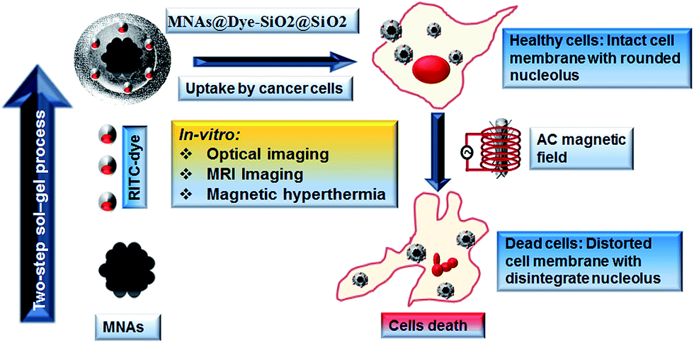 | ||
| Fig. 1 Schematic diagram shows the synthesis and theranostic application of MNAs@Dye–SiO2@SiO2 for cancer therapy. | ||
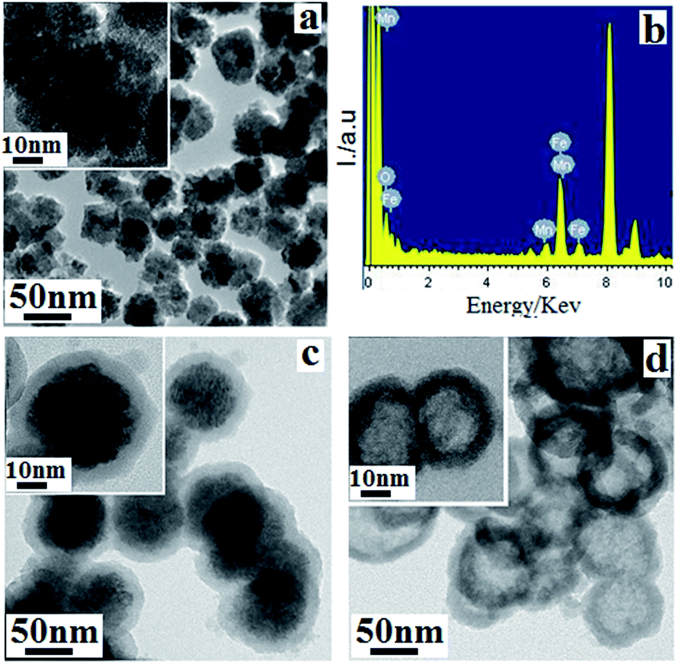 | ||
| Fig. 2 (a) TEM images show the spherical morphology of the MNAs and (b) EDX analysis for elemental composition confirms the presence of manganese, iron and oxygen. (c) TEM images showing the silica coating over the MNAs and (d) the hollow silica sphere after dissolution of the iron core in an acidic buffer solution (pH 4) indicate the presence of a mesoporous silica shell over the MNAs. All insets show magnified images. | ||
The cores of the MNAs are black spheres with an average size of around ∼50 nm (ESI Fig. 1†), and the grey silica shell has an average thickness of ∼15–20 nm (Fig. 2c). This core shell structure of MNAs@Dye–SiO2@SiO2 clearly visible by the difference of electrons permeability of MNAs and silica shell (Fig. 2c). The overall size of MNAs@Dye–SiO2@SiO2 falls in between 60–80 nm, which is within the size range recommended for drug or gene delivery applications.7,8 The crystal structure of the as synthesized MNAs was investigated using X-ray diffraction (XRD, ESI Fig. 2a†). The MNAs crystallize in an inverse spinel magnetite structure of Fe3O4. The characteristic diffraction peaks are indexed as (220), (311), (400), (422), (611), and (440) planes following the standard data (JCPDS card 19-0629). The structure is not changed because of the similar ionic radii of Mn2+ and Fe2+. However, a slight shift (towards lower 2theta) in position with respect to that of Fe3O4 is observed due to lattice strain. The (311) peak was further analyzed by fitting it to a Gaussian distribution to obtain its full width at half-maximum (FWHM; ESI Fig. 2a†). The average crystallite size was estimated as ∼11.3 nm using the Debye–Scherrer equation. The formation mechanism of the MNAs, as described in the earlier reports, follows a two-stage growth process. First the precursor is attained at the supersaturating temperature for nucleation, and then primary nanoparticles start nucleating to a form an aggregate at a high temperature.2,4
MnFe2O4 nanoparticles are reported to have a high magnetization in comparison to most other ferrites.1 The heating efficiency under an AC magnetic field and MRI contrast enhancement of magnetic nanoparticles increases with magnetization.18 The magnetization plots of the MNAs and MNAs@Dye–SiO2@SiO2 were determined at 300 K (ESI Fig. 2b†), and exhibit superparamagnetic behaviour with the highest magnetization (Ms) values of 90.43 emu g−1 and 62.45 emu g−1 (Mn + Fe) respectively. The former is higher compared to the Fe3O4 nanoassemblies (∼65 emu g−1).2 The same phenomenon of high magnetization was also observed with other assemblies of MNPs.19,20 The reason for a high Ms value in MnFe2O4, as described in earlier reports, is due to the partial substitution of Mn2+ at the tetrahedral sites in the spinel structure, which modulates the antiferromagnetic coupling interactions between the magnetic ions in the octahedral and tetrahedral sites, resulting in the increase of the net magnetization of the nanoparticles18,21 The N2 adsorption–desorption isotherms exhibit a characteristic type IV isotherm with H1-hysteresis loops, demonstrating their mesoporous characteristics (ESI Fig. 2c†).2,4 The average pore diameter calculated using the Barrett–Joyner–Halenda (BJH) method was 3.3 nm, and the Brunauer–Emmett–Teller (BET) surface area and total pore volume measured to be 175.3 m2 g−1, and 0.35 cm3 g−1, respectively. The nanostructure, with a high surface area, large pore volume, and uniform accessible mesopores, was demonstrated as a potential nanocarrier for cancer diagnosis and therapy.22,23 In order to demonstrate the highly permeable nature of the silica shell, MNAs@Dye–SiO2@SiO2 was dispersed in an acetate buffer solution (pH 4.0) and stirred for 4 h to etch away the MNA core. Fig. 2d, shows the TEM image of the hollow silica nanoparticles formed after dissolution of the magnetic core in an acidic buffer solution (pH 4.0). This confirms the mesoporous nature of MNAs@Dye–SiO2@SiO2.
An MTT assay was performed to determine the viability of HeLa cells after incubation with different concentrations of MNAs@Dye–SiO2@SiO2 for 24 and 48 h (ESI Fig. 3†). The viability of the control cells (without MNAs@Dye–SiO2@SiO2) was assumed to be 100%. We observed a cell viability of about 90% as compared to the control cells, even at a higher concentration of metal ions (600 μg, Mn + Fe/mL) after 24 h incubation. These results clearly indicate that MNAs@Dye–SiO2@SiO2 has low cytotoxicity. To demonstrate the optical imaging functionality of MNAs@Dye–SiO2@SiO2, the cellular uptake was observed by fluorescence microscopy. Fig. 3a and b show the confocal images of HeLa cells containing the red fluorescent granulated particles dispersed homogenously in the cell cytoplasm, which confirm the uptake of MNAs@Dye–SiO2@SiO2 by HeLa cells after 24 h of incubation. The uptake results confirmed the optical imaging efficacy of MNAs@Dye–SiO2@SiO2.
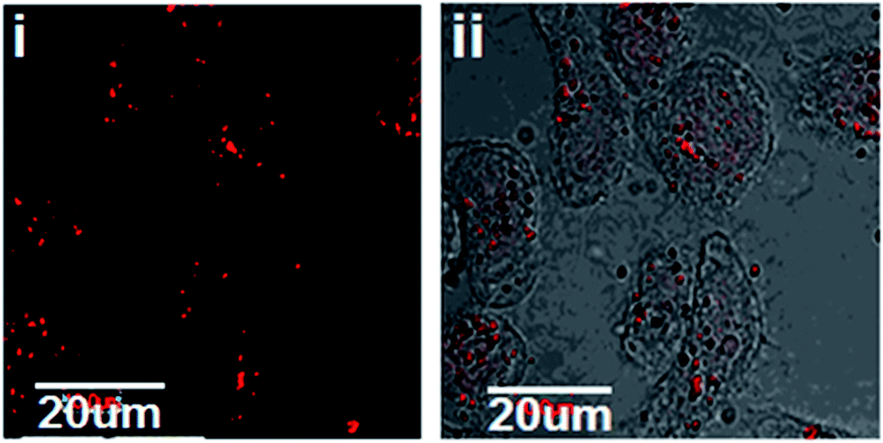 | ||
| Fig. 3 (i and ii) show the confocal laser scanning microscopy (CLSM) images of HeLa cells with various concentrations of RITC dye-doped MNAs@Dye–SiO2@SiO2 after 24 h of incubation. The spot-like red fluorescence inside the cell cytoplasm shows the uptake of MNAs@Dye–SiO2@SiO2. | ||
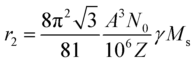
The next step was to evaluate their efficacy as potential T2 MRI contrast agents. In MRI, superparamagnetic nanoparticles generate a strong magnetic field in homogeneities around the vicinity of water molecules to accelerate the relaxation of the water proton (1H) magnetization.19,21 We have determined the longitudinal (r1) and transverse (r2) relaxivities of MNAs@Dye–SiO2@SiO2 in agar phantom using a 9.4 Tesla vertical-bore MRI scanner.3 Fig. 4a and b show the inverse relaxation times, 1/T1 and 1/T2, as a function of the molar concentration of (Fe + Mn). It was observed that the inverse relaxation times varied linearly with the (Fe + Mn) concentration and the slope is defined as the longitudinal (r1) and transverse (r2) relaxivities, respectively. Based on a classical relaxation model, the small size (<100 nm) MNAs@Dye–SiO2@SiO2 nanoparticles fall within the size range of the static dephasing regime (SDR).24,25 In the SDR, nanoparticles are predicted to exhibit the highest r2 relaxivity, which is independent of their size. The r2 value of the nanoparticle in the SDR is determined by the equation:26
 | (1) |
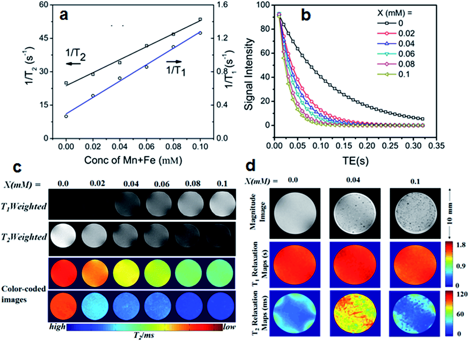 | ||
| Fig. 4 (a) Spin–lattice 1/T1 and spin–spin 1/T2 relaxation rates of MNAs@Dye–SiO2@SiO2 at different metals ion concentrations (detonated X = (Mn + Fe). (b) T2 relaxation curves of various magnetic nanoparticle formulations in phantom agarose gel. (c) T1- and T2-weighted MR images of agarose phantoms at different concentrations of MNAs@Dye–SiO2@SiO2 and their respective color coded images. (d) T2 weighted MR images of dispersed HeLa cell in agarose gel phantoms after 24 h of incubation with different concentrations of MNAs@Dye–SiO2@SiO2. | ||
It has been demonstrated that the surface coating on MNPs has an influential role in enhancing the relaxivity through minimizing the effects of surface oxidation, magnetic disorder or spin canting.24,32 However, studies have also shown that the relaxivity depend on water diffusion based on the nature and thickness of the coating material.29–31 The mesoporous nature of MNAs are also advantageous to enhance MRI sensitivity by allowing the dipolar interactions between the magnetic moment of the particle and the surrounding water protons, which contribute to the shortening of the T2 relaxation time and dephasing of protons.25,27 This allows more metal ions to be exposed to water molecules at the inner surface. The strength of MNAs@Dye–SiO2@SiO2 as a positive contrast agent was also confirmed in MR images of agar phantom with different concentrations (from 20 to 100 μg mL−1 in terms of metal ions). The labeling efficacy of MNAs@Dye–SiO2@SiO2 was demonstrated with HeLa cells. The MNAs@Dye–SiO2@SiO2 labeled HeLa cells were dispersed in agarose gel to image on a 9.4 T MRI scanner. As evident from Fig. 4d, a concentration-dependent signal enhancement (dark-contrast in the T2-weighted image) was observed in the MR images of HeLa cells treated with MNAs@Dye–SiO2@SiO2 compared with untreated cancer cells. Lartigue et al. also observed an increase in the signal intensity of multicore iron oxide labelled A549 cells in agarose gel.19 Our results confirmed the efficacy of MNAs@Dye–SiO2@SiO2 as potential MRI nanoprobes for cancer diagnosis or cell labelling in stem cell therapy.
Previously, silica encapsulated magnetic nanoparticles have been used for cancer hyperthermia.33 We have also evaluated the heating efficacy of MNAs@Dye–SiO2@SiO2 for magnetic hyperthermia. The SAR value of MNAs@Dye–SiO2@SiO2 was measured over a wide range of magnetic field amplitudes at a constant frequency of 250 kHz (Fig. 5a). The SAR value of MNAs@Dye–SiO2@SiO2 dispersed in PBS (conc. 0.5 mg mL−1 in terms of metal ions) reached 375 ± 20 W g−1, 330 ± 15 W g−1, and 218 ± 30 W g−1 under an external magnetic field of 33.3 kA m−1, 26 kA m−1, and 13.3 kA m−1 respectively, at a constant frequency of 250 kHz (Fig. 5a). This shows the dependence of SAR on various parameters such as saturation magnetization, applied AC magnetic field strength and frequency.19,34 The SAR value of MNAs@Dye–SiO2@SiO2 increases proportionally to the magnetic field strength as reported by Lartigue et al. for multicore iron oxide nanoparticle and Guardia et al. for 19 nm iron oxide nanocubes19,35 To evaluate the heating effect on cancer cells, the cells pellet with a concentration of 2 × 10⁶ in a 1 mL aqueous suspension of MNAs@Dye–SiO2@SiO2 (0.5 mg mL−1 ∼in terms of metal ion concentration Mn + Fe at H = 13.3 kA m−1, f = 250 kHz, Hf factor = 3.3 × 10⁹ A m−1 s−1), was thermally activated for 30 min at a temperature between 42°C–45 °C. The safe range of applied AC magnetic fields has been demonstrated, where the product Hf does not exceed 5 × 10⁹ A m−1 s−1 at a clinical level for the human body.36,37 We have performed magnetic hyperthermia treatment in cancer cells at a relatively small Hf value (3.3 × 10⁹ A m−1 s−1), and it was agreeable that the hyperthermia treatment with MNAs@Dye–SiO2@SiO2 could be administered at a safe and tolerable range of Hf factor without any toxic or deleterious side effect. An MTT assay was performed to determine the cell viability with and without magnetic hyperthermia. The heating effect of MNAs@Dye–SiO2@SiO2 caused ∼80–85% cancer cell death with respect to control cells (Fig. 5b). The ESI Fig. 4i and ii† show the phase contrast images of control HeLa cells and MHT treated cells. The HeLa cells show complete distortion of the cell membrane after MHT treatment in comparison to the control cells. This revealed that the observed anticancer activity did not originate from the magnetic targeting of MNAs@Dye–SiO2@SiO2 to the cells, but was due to their induced heating effects. The same phenomenon of cell death was observed by Prasad et al. using γ-MnxFe2−xO3 nanoparticles in HeLa cancer cell and Bae et al. in human lung carcinoma A549 cells with chitosan-coated ferrimagnetic iron oxide cube nanoparticles.38,39 Furthermore, to confirm the cell death through apoptosis, the cancer cells were stained with phalloidin–tetramethylrhodamine-B-isothiocyanate for actin filaments and the nuclei were stained with 4,6-diamidino-2-phenylindole dye (DAPI). The morphologies of the control and heat treated cells were imaged by confocal microscopy (Fig. 5ci and ii). The confocal images clearly show the apoptosis of the cancer cells through cell membrane blebbing, distortion of actin filaments and denaturation of the nuclear compartment (Fig. 5ci and ii). These are the prominent morphological markers of apoptosis in cells. Yoo et al. also demonstrated the same phenomenon of hyperthermia mediated cancer cell death caused through apoptosis rather than the necrosis.40 These imply that the present superparamagnetic MNAs@Dye–SiO2@SiO2 nanocomposite combined with its functionality of magnetic hyperthermia, would be a potential theranostic agent for simultaneous optical/MR imaging and thermal therapy for cancer treatment.
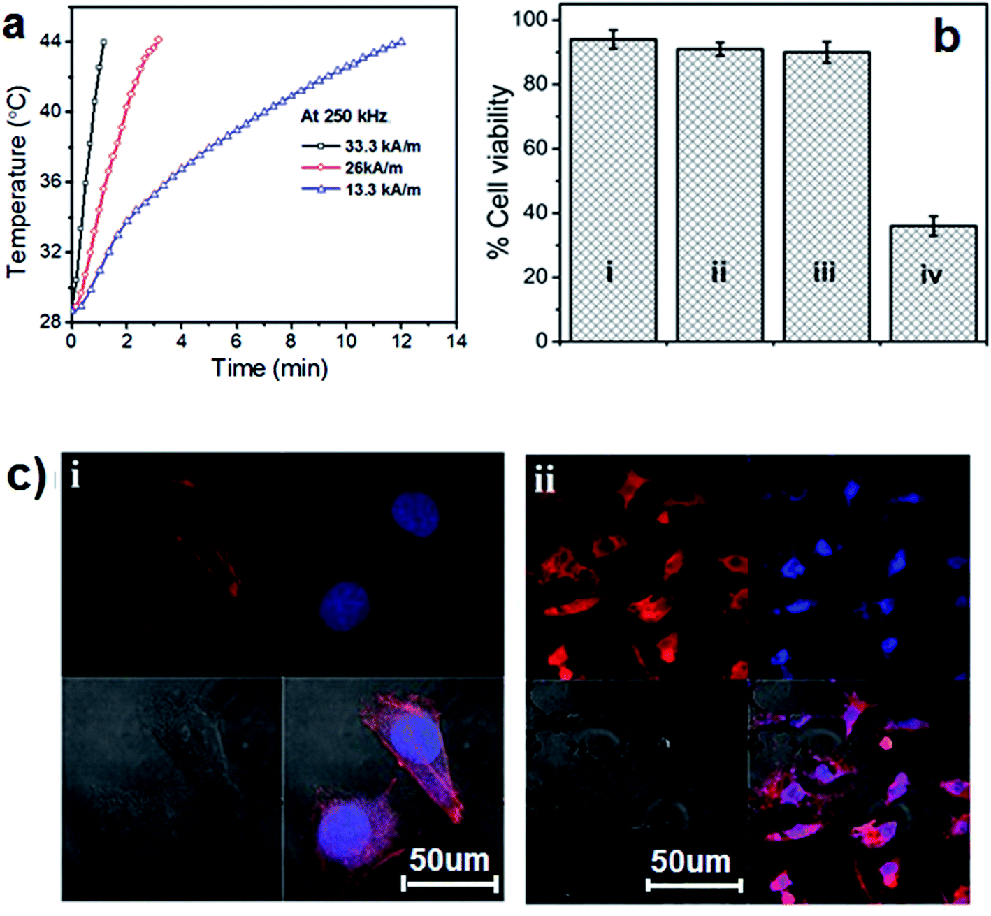 | ||
| Fig. 5 a) The calorimetric profile of MNAs@Dye–SiO2@SiO2 with respect to time. (b) The quantitative estimation of cancer cell death by an MTT assay: (bi) control HeLa cells, (bii) cells incubated with MNAs@Dye–SiO2@SiO2, w/o MHT, (biii) cells w/o MNAs@Dye–SiO2@SiO2 with MHT treatment, and (biv) with both MNAs@Dye–SiO2@SiO2 and MHT treatment. (ci) Confocal images of control HeLa cells without MHT or MNAs@Dye–SiO2@SiO2 and (cii) MHT-induced cancer cell death, shows the loss of cell-membrane integrity, membrane shrinkage and disintegration of the genetic materials and the nucleus, a morphological indication of cell apoptosis. The cancer cells were stained with phalloidin–tetramethyl rhodamine-B-isothiocyanate (red) for actin filaments and the nuclei were stained by DAPI (4′,6-diamidino-2-phenylindole; blue). | ||
3. Conclusions
In summary, MNAs@Dye–SiO2@SiO2 represents a facile strategy for the preparation of highly potent superparamagnetic, silica encapsulated MnFe2O4 nanoassemblies with fluorescent dyes. Compared with other magnetic nanoassemblies, MNAs@Dye–SiO2@SiO2 exhibited a small size (<100 nm), high colloidal stability, high saturation magnetization, low cytotoxicity, enhanced relaxivities for T2 MRI contrast imaging and enhanced SAR values for magnetic hyperthermia. The in vitro studies with HeLa cells confirmed the efficacy of MNAs@Dye–SiO2@SiO2 for providing high T2 relaxivity and heat at a reduced dosage, fulfilling an essential requirement for the development of an iron-oxide based cancer theranostic nanosystem. Furthermore, the versatile surface functionality and encapsulation efficiency of the silica matrix for other types of metallic nanoparticles or chemotherapeutics will help in fabricating a more robust multifunctional theranostic nanosystem for cancer therapy.4. Experimental section
4.1 Reagents and materials
All the chemicals were of analytical grade and used as received. Iron(III) chloride hexahydrate (FeCl3·6H2O, 98.9%), manganese chloride(II) tetrahydrate (MnCl2·4H2O, 98%), tetraethyl orthosilicate (TEOS), 3-aminopropyltriethoxysilane (APTES, 98%), rhodamine-B isothiocyanate (RITC, 99% Aldrich), cetyltrimethylammoniumbromide (CTAB, 99%), 3-(4,5-dimethyl-thiazol-2yl)-2,5-diphenyl tetrazolium bromide (MTT, 98%), phalloidin–tetramethylrhodamine B-isothiocyanate conjugates and 4,6-diamidino-2-phenylindole (DAPI, 98%) were purchased from Sigma-Aldrich Co. (St. Louis, MO, USA). Anhydrous sodium acetate and ethylene glycol (EG) were purchased from Merck Chemical Ltd. Dulbecco’s modified eagle medium (DMEM), antibiotic and antimycotic solution were obtained from Hi-Media Ltd (Mumbai, India) and HeLa cancer cell lines were procured from the National Centre of Cell Science (NCCS, Pune, India). All tissue culture plates and flasks were purchased from NUNC (USA). The Milli-Q water with a resistivity of 18.2 MΩ cm was used for all experiments.4.2 Synthesis of MNAs@Dye–SiO2@SiO2
The 0.10 g of MNAs (∼50 nm), synthesized by a modified polyol method, was ultrasonicated in 0.1 M HCl aqueous solution (20 mL) for 10 min.2,7 After that the acid treated MNAs were homogeneously dispersed in an aqueous solution of ethanol (80 mL), DI water (20 mL) and cetyltrimethylammoniumbromide (0.35 g, CTAB). The suspension was vigorously stirred for 30 min. After stirring, the concentrated aqueous ammonia solution (1.5 mL, 25 wt%) was added to the suspension, followed by dropwise addition of tetraethyl orthosilicate (TEOS, 0.5 mL) with 100 μL of APS-modified dye solution as described by Lee et al.16 The whole reaction dispersion was stirred at room temperature for 12 h to form the silica shell over the MNAs. For further silica coating, the products were separated by a magnet and washed 2–3 times with ethanol and water alternatively, and then redispersed in a mixed solution of CTAB (0.2 g), ethanol (80 mL), DI water (20 mL) and aqueous ammonia solution (1 mL). After mixing homogeneously for 30 min, the TEOS (0.25 mL) was then added dropwise to the solution with stirring. The synthesized products were separated using a magnet, washed with ethanol and water alternatively to remove undesirable nonmagnetic by-products and dried in air at 80 °C for 24 h. The surfactant CTAB was removed by refluxing in an acidic ethanolic solution (0.75 mL concentrated HCl/100 mL ethanol solution) for 4 h.4.3 Characterization techniques
Powder X-ray diffraction (XRD) patterns of the MNAs and SiO2@MNAs were obtained on the PANalytical X’Pert PRO diffractometer (PW3040/60) with Cu Kα radiation (λ = 1.5405 Å) and a Ni filter. All patterns were recorded over the angular range 10 ≤ 2θ/deg ≤ 80 with a step size of Δ2θ = 0.02. The nitrogen (N2) adsorption–desorption isotherms and pore size distributions were measured with an accelerated surface area and porosimetry instrument (ASAP 2020, Micrometrics USA). The surface area was determined using the BET equation from the N2 adsorption–desorption isotherms between P/P0 = 0–0.2. Prior to measurement, the sample was degassed at 120 °C for 6 h. Transmission electron microscopy (TEM) and energy dispersive X-ray (EDX) analyses were performed using a JEOL JEM-2100F electron microscope with an accelerating voltage of 200 keV. The sample was diluted in ethanol and drop cast onto the surface of a TEM grid (Ted Pella, Inc., Form var/Carbon 400 mesh). The particle size distribution was processed by Image-J software. The weight chemical analysis was performed using an inductively coupled plasma-atomic emission spectrometer (ICP-AES, ARCOS Germany). The analysis of the samples was done in comparison with the ICP-AES standard (Sigma). Magnetic properties of the samples were measured by a physical property measurement system (PPMS, Quantum Design). The measurements were recorded between −20![[thin space (1/6-em)]](https://www.rsc.org/images/entities/char_2009.gif) 000 and 20000 Oe at 300 K. The hydrodynamic diameter and size distribution of the particles were analysed by dynamic light scattering (DLS, Malvern Nano-ZS, l = 632.8 nm) with the samples dispersed in Milli-Q water. Simultaneously, the surface charge alteration of particles was probed by zeta potential (Malvern Nano-ZS).
000 and 20000 Oe at 300 K. The hydrodynamic diameter and size distribution of the particles were analysed by dynamic light scattering (DLS, Malvern Nano-ZS, l = 632.8 nm) with the samples dispersed in Milli-Q water. Simultaneously, the surface charge alteration of particles was probed by zeta potential (Malvern Nano-ZS).
4.4 In vitro cytotoxicity and uptake of MNAs@Dye–SiO2@SiO2
The HeLa cell line was cultured in 25 cm2 tissue culture flask containing DMEM medium supplemented with 10% fetal bovine serum (FBS), 1% antibiotic–antimycotic solution in a humidified incubator (37 °C, 5% CO2). MTT assay was performed on the HeLa cancer cells to evaluate the in vitro cytotoxicity of the MNAs@Dye–SiO2@SiO2. The HeLa cells were seeded in a 96-well plate at a density of 20000 viable cells per well and incubated for 24 h at 37 °C to allow cell attachment. The cells were treated with various concentrations of MNAs@Dye–SiO2@SiO2 (25, 50, 100, and 200 μg mL−1 ∼in terms of metal ions) and incubated for 24 h. The wells without the MNAs@Dye–SiO2@SiO2 treatment were used as the control. After an interval of 24 h, the cells were washed twice using PBS, then 20 μL of freshly prepared MTT solution (0.5 mg mL−1 in PBS-phosphate buffer saline 7.4) in 100 μL DMEM media was added into each well. The plates were incubated at 37 °C for 3 h. After removing the media, the MTT–formazan crystals were dissolved by adding 100 μL of dimethyl sulfoxide (DMSO) into the each well of the plate. The plate was placed on a shaking table for 5 minutes to mix the formazan into the solvent. The plate was then incubated for 3 h and the absorbance at 550 nm was quantified by a microplate reader (Victor 3-V Multilabel Plate Reader, PerkinElmer, USA). The formazan dye generated by the live cells was proportional to the number of live cells. Cells without nanoparticles were considered as the control. Results were quantified by manually subtracting the blank value from each value and normalizing against the control values. The data were averaged from three experiments for each MNAs@Dye–SiO2@SiO2 concentration.
4.5. MNAs@Dye–SiO2@SiO2 cellular uptake study
The uptake of MNAs@Dye–SiO2@SiO2 by HeLa cancer cells were observed by confocal microscopy imaging. The HeLa cells were cultured in a 12 well chamber plate with the culture medium (DMEM with L-glutamine, 10% FBS, 1% of antibiotic–antimycototic solution) at 37 °C in 5% CO2. The HeLa cells were seeded into chamber slides at a density of 20000 cells per well. After 24 h of incubation, the culture medium was replaced by fresh DMEM containing MNAs@Dye–SiO2@SiO2 at different metal ion concentrations. After 24 h of incubation in the presence of MNAs@Dye–SiO2@SiO2, each well was washed with 1× PBS three times, treated with 0.5 mL of 4% paraformaldehyde solution for 10 min to fix the cells, and followed by washing with 1× PBS three times. The cells were then mounted using Vectashield mounting medium and imaged by using a confocal laser scanning microscope (CLSM, Olympus Fluoview, FV500, Tokyo, Japan). The fluorescent image was acquired at (λex = 570 nm and λem = 590 nm) for rhodamine-B isothiocyanate (RITC). The 60× water immersion objective was used to acquire and analyze images using Fluoview software (Olympus, Tokyo, Japan).
4.6 MRI relaxation properties of MNAs@Dye–SiO2@SiO2 using phantom agar gels
Suspensions of MNAs@Dye–SiO2@SiO2 in the concentration range of 0–100 μg mL−1 (∼term of metal ions, Mn + Fe) were prepared in PBS. A 2.5% w/v agar solution was prepared by heating 250 mg of agar in 10 mL of PBS at 80 °C for 20 min.3 For the preparation of phantom gels, 160 μL of the above agar solution was mixed with 840 μL of MNAs@Dye–SiO2@SiO2 suspension at each concentration, and preheated to 60 °C to prevent gelation while mixing. MNAs@Dye–SiO2@SiO2 and agar gel were mixed thoroughly in warm conditions in a 1.5 mL centrifuge tubes by turning the tubes upside down repeatedly. An aliquot of 250 μL of this mixture was transferred quickly to a 1.5 mL micro-centrifuge tube and then allowed to cool to room temperature.MRI experiments were performed on a 9.4 T (400 MHz for protons) 89 mm vertical-bore MRI scanner (Agilent, Santa Clara, CA) equipped with triple axis gradients (maximum strength 100 G cm−1) and a 10 mm transmit/receive RF coil. T1 and T2 relaxation times for the samples were obtained using a multi-echo multi slice sequence (MEMS). To measure the T1 relaxation, 12 repetition times (TR) were arrayed exponentially from 50 to 4000 ms. The other parameters used for measuring the T1 relaxations were Echo Time (TE) = 8.4 ms, NE = 1, field of view = 10 × 10 mm, thickness = 1 mm, matrix, and 128 × 128 pixels. T2 relaxations were also obtained using a MEMS sequence with NE = 32, TE = 10 ms, TR = 4000, field of view = 10 × 10 mm, thickness = 1 mm, matrix, and 128 × 128 pixels. The data were exported to Matlab software (Mathworks, Natick, MA) to calculate the relaxation times along with their T1 and T2 maps using a nonlinear regression algorithm. Then r1 and r2 relaxivities were calculated based on the slope of the linear regression of the data points: (1/T1 and 1/T2) (s−1) versus metal ion concentrations.
4.7 In vitro MR imaging in HeLa cancer cells
For in vitro MR imaging, HeLa cells were seeded in a six well plate in 2 mL of media for 24 h. Subsequently, different concentrations of MNAs@Dye–SiO2@SiO2 (∼in terms of metal ions, Mn + Fe) 0, 25, and 100 μg mL−1 were added into each well. The medium was removed after 24 h and the cells were washed with PBS. The cells were detached using trypsin/EDTA and resuspended in DMEM media. The cell pellets were prepared by centrifugation at a speed of 2000 rpm for 5 min. The semisolid cell pellets were finally suspended in a 2% solution containing agarose and solidified at room temperature and then maintained at 4 °C. T1 and T2 relaxation maps were generated using multi-echo-spin-echo sequences (MEMS) acquired with the 9.4 T Agilent MRI scanners. T1 relaxation data were generated by acquisitions of 12 MEMS images with TR exponentially arrayed between 50 ms and 4000 ms; effective echo time TE = 10 ms; number of echoes NE, 1; FOV = 10 × 10 mm; NEX = 2; slice thickness = 1 mm; using a 128 × 128 matrix. Parameters for measuring the alteration of T2 relaxation times were: TR, 4000 ms; effective echo time TE, 10 ms; number of echoes NE, 32; NEX, 2; FOV, 10 × 10 mm; matrix, 128 × 128 pixels; slice thickness, 1 mm. Afterwards, the acquisitions data were transferred to a PC and processed by a MATLAB code to generate T1 and T2 maps.4.8 Hyperthermia measurement
The heat generating efficiency of MNAs@Dye–SiO2@SiO2 was performed by time-dependent calorimetric measurements using an RF generator (Easy Heat 8310, Ambrell, UK). In brief, 1 mL of aqueous suspension of MNAs@Dye–SiO2@SiO2 at concentrations ranging from 0.2 to 1 mg mL−1 (in terms of metals ions Mn + Fe) were subjected to varying magnetic fields (13.3 kA m−1, 26 kA m−1, 33.3 kA m−1 with a corresponding Hf factor, 3.3 × 10⁹ A m−1 s−1, 6.5 × 10⁹ A m−1 s−1,8.3 × 109 A m−1 s−1) using an RF generator operating at a fixed frequency of 250 kHz. The time-dependent temperature rise was monitored using a fluoro-optic fibre thermometer (Luxtron, Corp). The specific absorption rate (SAR) was calculated using the following equation.
 | (2) |
4.9 Magnetic hyperthermia in cancer cells
The HeLa cells were subjected to magnetic hyperthermia treatment (MHT) by a modified protocol.19 The HeLa cells were grown up to 90% confluence in a 75 cm2 culture flask. After 24 h, the DMEM medium was removed and the cell layer was washed three times with PBS, detached from the substratum and centrifuged at 2000 rpm for 5 min to get a cell pellet in a 15 mL sterile polypropylene tube. Then, 2 × 10⁶ HeLa cells were transferred into 1 mL DMEM medium containing 0.5 mg mL−1 of MNAs@Dye–SiO2@SiO2 (∼in term of metal ions concentrations, Mn + Fe) in a 2 mL Eppendorf tube. The tubes were finally exposed to a magnetic hyperthermia setup (H = 13.3 kA m−1, Hf factor = 3.3 × 10⁹ A m−1 s−1 at the center of a 4-turn copper tubing coil, diameter = 6 cm) at a constant operating frequency of 250 kHz. When the temperature reached around 42-45 °C, the field was adjusted to maintain the temperature at 43 °C for 30 minutes. For a comparative study, HeLa cells were treated with MHT alone (without MNAs@Dye–SiO2@SiO2) and cells without any treatment were used as a control. After the thermal treatment, MNAs@Dye–SiO2@SiO2 was settled with magnet and supernatant was again removed and centrifuge to form cell pellet. The cell pellet was washed three times with PBS. Then, 100 μL of 2 × 10⁶ cells per mL were seeded in 96 well plates in 16 replicates for 24 h of incubation. The morphological features of the treated cells were observed by actin staining with phalloidin–tetramethyl rhodamine-B-isothicyanate and the nuclei were stained with 4,6-diamidino-2-phenylindole (DAPI) according to the protocol of Sigma-Aldrich. The cell viability was determined by an MTT (3-(4,5-dimethyl-thiazol-2yl)-2,5-diphenyl tetrazolium bromide) assay, as mentioned in Section 2. The absorbance was measured at 550 nm wavelength in a microplate reader (Victor 3 V Multilabel Plate Reader, Perkin-Elmer, USA).The percentage of cell viability was calculated using the following equation:
 | (3) |
Acknowledgements
This work is supported by Nano-mission, Department of Science and Technology (DST) and Nanotechnology Section, Department of Information Technology (DIT), Govt. of India. I am sincerely thankful to Mr Asif S Khan for his assistance with the magnetic hyperthermia experiment. Authors are also thankful to the Centre for Research in Nanotechnology and Science (CRNTS), I.I.T Bombay for providing TEM and SEM, and confocal microscopy facilities.References
- D. Yoo, J.-H. Lee, T.-H. Shin and J. Cheon, Theranostic magnetic nanoparticles, Acc. Chem. Res., 2011, 44, 863–874 CrossRef CAS PubMed.
- K. C. Barick, M. Aslam, L. Yen-Po, D. Bahadur, V. P. Pottumarthi and P. D. Vinayak, Novel and efficient MR active aqueous colloidal Fe3O4 nanoassemblies, J. Mater. Chem., 2009, 19, 7023–7029 RSC.
- M. Yallapu, S. Othman, E. Curtis, B. Gupta, M. Jaggi and S. Chauhan, Multi-functional magnetic nanoparticles for magnetic resonance imaging and cancer therapy, Biomaterials, 2011, 32, 1890–1905 CrossRef CAS PubMed.
- S. Kumar, A. Daverey, N. K. Sahu and D. Bahadur, In vitro evaluation of PEGylated mesoporous MgFe2O4 magnetic nanoassemblies (MMNs) for chemo-thermal therapy, J. Mater. Chem. B, 2013, 1, 3652–3660 RSC.
- S. Dutz and R. Hergt, Magnetic particle hyperthermia – a promising tumour therapy?, Nanotechnology, 2014, 25, 452001 CrossRef PubMed.
- J. Lee, N. Lee, H. Kim, J. Kim, S. Choi, J. Kim, T. Kim, I. Song, S. Park, W. Moon and T. Hyeon, Uniform mesoporous dye-doped silica nanoparticles decorated with multiple magnetite nanocrystals for simultaneous enhanced magnetic resonance imaging, fluorescence imaging, and drug delivery, J. Am. Chem. Soc., 2010, 132, 552–557 CrossRef CAS PubMed.
- G. Shili, Y. Piaoping, L. Chunxia, W. Wenxin, D. Yunlu, N. Na and L. Jun, Synthesis of Magnetic, Up-Conversion Luminescent, and Mesoporous Core–Shell-Structured Nanocomposites as Drug Carriers, Adv. Funct. Mater., 2010, 20, 1166–1172 CrossRef PubMed.
- Y. Chen, H. Chen and J. Shi, In vivo bio-safety evaluations and diagnostic/therapeutic applications of chemically designed mesoporous silica nanoparticles, Adv. Mater., 2013, 25, 3144–3176 CrossRef CAS PubMed.
- J. Gao, H. Gu and B. Xu, Multifunctional magnetic nanoparticles: design, synthesis, and biomedical applications, Acc. Chem. Res., 2009, 42, 1097–1107 CrossRef CAS PubMed.
- M. J. Sailor and J. H. Park, Hybrid nanoparticles for detection and treatment of cancer, Adv. Mater., 2012, 24, 3779–3802 CrossRef CAS PubMed.
- J. E. Lee, N. Lee, T. Kim, J. Kim and T. Hyeon, Multifunctional mesoporous silica nanocomposite nanoparticles for theranostic applications, Acc. Chem. Res., 2011, 44, 893–902 CrossRef CAS PubMed.
- K. Pohaku Mitchell, A. Liberman, A. Kummel and W. Trogler, Iron(III)-doped, silica nanoshells: a biodegradable form of silica, J. Am. Chem. Soc., 2012, 134, 13997–14003 CrossRef CAS PubMed.
- N. Insin, J. B. Tracy, H. Lee, J. P. Zimmer, R. M. Westervelt and M. G. Bawendi, Incorporation of iron oxide nanoparticles and quantum dots into silica microspheres, ACS Nano, 2008, 2, 197–202 CrossRef CAS PubMed.
- F. Zhang, G. B. Braun, A. Pallaoro, Y. Zhang, Y. Shi, D. Cui, M. Moskovits, D. Zhao and G. D. Stucky, Mesoporous multifunctional upconversion luminescent and magnetic “nanorattle” materials for targeted chemotherapy, Nano Lett., 2012, 12, 61–67 CrossRef CAS PubMed.
- M. Montalti, L. Prodi, E. Rampazzo and N. Zaccheroni, Dye-doped silica nanoparticles as luminescent organized systems for nanomedicine, Chem. Soc. Rev., 2014, 43, 4243–4268 RSC.
- J. Lee, N. Lee, H. Kim, J. Kim, S. Choi, J. Kim, T. Kim, I. Song, S. Park, W. Moon and T. Hyeon, Uniform mesoporous dye-doped silica nanoparticles decorated with multiple magnetite nanocrystals for simultaneous enhanced magnetic resonance imaging, fluorescence imaging, and drug delivery, J. Am. Chem. Soc., 2010, 132, 552–557 CrossRef CAS PubMed.
- A. Burns, H. Ow and U. Wiesner, Fluorescent core–shell silica nanoparticles: towards “Lab on a Particle” architectures for nanobiotechnology, Chem. Soc. Rev., 2006, 35, 1028–1042 RSC.
- I. Obaidat, B. Issa and Y. Haik, Magnetic Properties of Magnetic Nanoparticles for Efficient Hyperthermia, Nanomaterials, 2015, 5, 63–89 CrossRef CAS PubMed.
- L. Lartigue, P. Hugounenq, D. Alloyeau, S. Clarke, M. Lévy, J.-C. Bacri, R. Bazzi, D. Brougham, C. Wilhelm and F. Gazeau, Cooperative organization in iron oxide multi-core nanoparticles potentiates their efficiency as heating mediators and MRI contrast agents, ACS Nano, 2012, 6, 10935–10949 CrossRef CAS PubMed.
- Y. Qi, C. Shao, W. Gu, F. Li, Y. Deng, H. Li and L. Ye, Carboxylic silane-exchanged manganese ferrite nanoclusters with high relaxivity for magnetic resonance imaging, J. Mater. Chem. B, 2013, 1, 1846–1851 RSC.
- J.-t. Jang, H. Nah, J.-H. Lee, S. Moon, M. Kim and J. Cheon, Critical enhancements of MRI contrast and hyperthermic effects by dopant-controlled magnetic nanoparticles, Angew. Chem., Int. Ed., 2009, 48, 1234–1238 CrossRef CAS PubMed.
- S. Xuan, F. Wang, J. M. Lai, K. W. Sham, Y. X. Wang, S. F. Lee, J. C. Yu, C. H. Cheng and K. C. Leung, Synthesis of biocompatible, mesoporous Fe(3)O(4) nano/microspheres with large surface area for magnetic resonance imaging and therapeutic applications, ACS Appl. Mater. Interfaces, 2011, 3, 237–244 CAS.
- S. H. Xuan, S. F. Lee, J. T. Lau, X. Zhu, Y. X. Wang, F. Wang, J. M. Lai, K. W. Sham, P. C. Lo, J. C. Yu, C. H. Cheng and K. C. Leung, Photocytotoxicity and magnetic relaxivity responses of dual-porous gamma-Fe2O3@meso-SiO2 microspheres, ACS Appl. Mater. Interfaces, 2012, 4, 2033–2040 CAS.
- Q. Vuong, J.-F. Berret, J. Fresnais, Y. Gossuin and O. Sandre, A universal scaling law to predict the efficiency of magnetic nanoparticles as MRI T(2)-contrast agents, Adv. Healthcare Mater., 2012, 1, 502–512 CrossRef CAS PubMed.
- T.-J. Yoon, H. Lee, H. Shao, S. Hilderbrand and R. Weissleder, Multicore assemblies potentiate magnetic properties of biomagnetic nanoparticles, Adv. Mater., 2011, 23, 4793–4797 CrossRef CAS PubMed.
- N. Lee, Y. Choi, Y. Lee, M. Park, W. K. Moon, S. H. Choi and T. Hyeon, Water-dispersible ferrimagnetic iron oxide nanocubes with extremely high r(2) relaxivity for highly sensitive in vivo MRI of tumors, Nano Lett., 2012, 12, 3127–3131 CrossRef CAS PubMed.
- L. Li, W. Jiang, K. Luo, H. Song, F. Lan, Y. Wu and Z. Gu, Superparamagnetic iron oxide nanoparticles as MRI contrast agents for non-invasive stem cell labeling and tracking, Theranostics, 2013, 3, 595–615 CrossRef PubMed.
- N. Lee and T. Hyeon, Designed synthesis of uniformly sized iron oxide nanoparticles for efficient magnetic resonance imaging contrast agents, Chem. Soc. Rev., 2012, 41, 2575–2589 RSC.
- L. LaConte, N. Nitin, O. Zurkiya, D. Caruntu, C. O’Connor, X. Hu and G. Bao, Coating thickness of magnetic iron oxide nanoparticles affects R2 relaxivity, J. Magn. Reson. Imaging, 2007, 26, 1634–1641 CrossRef PubMed.
- S. Pinho, G. Pereira, P. Voisin, J. Kassem, V. Bouchaud, L. Etienne, J. Peters, L. Carlos, S. Mornet, C. Geraldes, J. Rocha and M.-H. Delville, Fine tuning of the relaxometry of γ-Fe2O3@SiO2 nanoparticles by tweaking the silica coating thickness, ACS Nano, 2010, 4, 5339–5349 CrossRef CAS PubMed.
- E. Pöselt, H. Kloust, U. Tromsdorf, M. Janschel, C. Hahn, C. Maßlo and H. Weller, Relaxivity optimization of a PEGylated iron-oxide-based negative magnetic resonance contrast agent for T2-weighted spin-echo imaging, ACS Nano, 2012, 6, 1619–1624 CrossRef PubMed.
- R. Brooks, T(2)-shortening by strongly magnetized spheres: a chemical exchange model, Magn. Reson. Med., 2002, 47, 388–391 CrossRef CAS PubMed.
- F. M. Martin-Saavedra, E. Ruiz-Hernandez, A. Bore, D. Arcos, M. Vallet-Regi and N. Vilaboa, Magnetic mesoporous silica spheres for hyperthermia therapy, Acta Biomater., 2010, 6, 4522–4531 CrossRef CAS PubMed.
- S. Dutz and R. Hergt, Magnetic nanoparticle heating and heat transfer on a microscale:Basic principles, realities and physical limitations of hyperthermia for tumour therapy, Int. J. Hyperthermia, 2013, 29, 790–800 CrossRef PubMed.
- H. Mamiya and B. Jeyadevan, Hyperthermic effects of dissipative structures of magnetic nanoparticles in large alternating magnetic fields, Sci. Rep., 2011, 1, 157 Search PubMed.
- R. Hergt, S. Dutz and M. Roder, Effects of size distribution on hysteresis losses of magnetic nanoparticles for hyperthermia, J. Phys.: Condens. Matter, 2008, 20, 385214 CrossRef PubMed.
- P. Guardia, R. Di Corato, L. Lartigue, C. Wilhelm, A. Espinosa, M. Garcia-Hernandez, F. Gazeau, L. Manna and T. Pellegrino, Water-soluble iron oxide nanocubes with high values of specific absorption rate for cancer cell hyperthermia treatment, ACS Nano, 2012, 6, 3080–3091 CrossRef CAS PubMed.
- N. K. Prasad, K. Rathinasamy, D. Panda and D. Bahadur, Mechanism of cell death induced by magnetic hyperthermia with nanoparticles of γ-MnxFe2−xO3 synthesized by a single step process, J. Mater. Chem., 2007, 17, 5042–5051 RSC.
- K. Bae, M. Park, M. Do, N. Lee, J. Ryu, G. Kim, C. Kim, T. Park and T. Hyeon, Chitosan oligosaccharide-stabilized ferrimagnetic iron oxide nanocubes for magnetically modulated cancer hyperthermia, ACS Nano, 2012, 6, 5266–5273 CrossRef CAS PubMed.
- D. Yoo, H. Jeong, S. H. Noh, J. H. Lee and J. Cheon, Magnetically triggered dual functional nanoparticless for resistance-free apoptotic hyperthermia, Angew. Chem., Int. Ed., 2013, 52, 13047–13051 CrossRef CAS PubMed.
Footnote |
| † Electronic supplementary information (ESI) available. See DOI: 10.1039/c5ra07632c |
| This journal is © The Royal Society of Chemistry 2015 |