
Fabrication, biofunctionalization, and simultaneous multicolor emission of hybrid “dots-on-spheres” structures for specific targeted imaging of cancer cells†
Jaeguk Nohab,
Daigeun Kima,
Geunseok Janga,
Jongho Kima,
Min Beom Heoc,
Na-Eun Leec,
Chang-Yeon Kimd,
Eunji Leec,
Youn-Joong Kimcd,
Yong Taik Lime and
Taek Seung Lee*a
aDepartment of Advanced Organic Materials and Textile System Engineering, Organic and Optoelectronic Materials Laboratory, Chungnam National University, Daejeon 305-764, Korea. E-mail: tslee@cnu.ac.kr
bAEZIS, 11-19 Deokgeum-ro 87beon-gil, Maedong-myeon, Eumseong-gun, Chungbuk369-812, Korea
cGraduate School of Analytical Science and Technology, Chungnam National University, Daejeon 305-764, Korea
dDivision of Electron Microscopic Research, Korea Basic Science Institute, Daejeon 305-333, Korea
eSKKU Advanced Institute of Nanotechnology (SAINT), School of Chemical Engineering, Sungkyunkwan University, Suwon 440-746, Korea
First published on 27th August 2014
Abstract
We report a simple technique for the fabrication of dots-on-spheres (DoS) structures in which conjugated polymer dots (CPdots) are immobilized on the surface of silica spheres via charged interaction. Red-, green-, and blue-emissive conjugated polymers were synthesized and employed to validate the feasibility of an approach to develop a DoS system with emission across the visible range. The robust binding of CPdots to silica particles provides a buffer resistance and good stability to photoirradiation and mechanical agitation. Further bioconjugation of the DoS system is achieved by the introduction of polyarginine and neu antibody that is specific for the HER2 receptor, leading to their successful application to targeted imaging of SKBR-3 breast cancer cells overexpressing HER2. Moreover, DoS with simultaneous multicolor emissions of red, green, and blue can be easily synthesized and used to demonstrate the versatility of this strategy for multicolor cellular imaging based upon a single excitation source. We believe that this hybrid DoS strategy and the easy fabrication of organic polymer nanoparticles with silica substrates will facilitate their effective integration of organic and inorganic materials into versatile applications.
1. Introduction
Recently, numerous types of nanoparticles used in the areas of optoelectronics, live cell imaging, and biosensing have received great attention.1–7 A wide variety of fluorescent nanoparticles have been made from organic,8–10 inorganic,11–13 and hybrid materials.14,15 In particular, nanoparticles composed of conjugated polymers dots, CPdots, which have the combined advantages of nanostructures and conjugated systems, have attracted considerable attention as a promising new class of emissive materials for bio- and medicinal applications.16–21CPdots have interesting features including their easy fabrication, high absorption coefficient, high brightness, good photostability, low cytotoxicity, large absorption cross-sections, and facile surface modification for bioconjugation, compared with competing materials including organic dyes and inorganic quantum dots.22–26 Moreover, CPdots show specific properties including potentially unlimited variation in their chemical structure, ready surface modification for chemical- and bioligands, and easy separation and purification after such modifications compared with fluorescent conjugated polyelectrolytes, which usually have ionic charges leading to unwanted, nonspecific interactions during cellular uptake and biological sensing.
Developing more efficient targeted imaging and specific detection of cells using CPdots remain challenging because the efficiency and specificity of multicolor imaging and targeted sensing by CPdots are still unsatisfactory. To improve these shortcomings, the preparation of multicolor conjugated polymer nanoparticle systems has been developed.6,27–29 In such systems, undesired Förster resonance energy transfer (FRET) between donors and acceptors often occurs because two or three CPdots with different emissions (red, green, or blue) exist in a confined space causing FRET, leading to more intense longer wavelength emission, which creates a hurdle for color tuning. Therefore, spatial isolation of each CPdot is necessary to control the donor–acceptor distance and prevent FRET.30
A wide variety of materials have been employed as substrates to fabricate and incorporate various nanoprobes. Among them, silica is a popular material traditionally used as a matrix for incorporating functional molecules.13,31 Efficient features of silica stem from its inherent lack of toxicity, high thermal stability, and transparency.32,33 Silica particles have many advantages in their application to biodetection and photonic devices because they have well-defined texture and roughness that can be easily altered.34–36 Besides, silica particles have been frequently used as a supporting matrix for the development of new nanoscopic hybrid materials, including fluorescent tags, sensors, and catalysts.37–41 Most interestingly and importantly, the well-established chemistry of silica surface enables us to provide versatile ways to immobilize functional species onto the silica surface to probe target analytes. Several methods to encapsulate CPdots into silica for further use of the silica surface for bioconjugation have been reported, but they suffer from poor formation of a well-defined core–shell structure and further attenuated brightness of the CPdot core because of the encapsulating silica shell.41–43 In this work, therefore, the silica particle was employed as a supporting matrix to envisage a multicolor targeted cell imaging.
Herein, we present an interesting strategy that uses a carefully-constructed “dots-on-spheres” (DoS) system as a reporter for biological targets. In this strategy, anionic CPdots and amino-functionalized silica spherical particles were first assembled into DoS using an electrostatic link to conjugate highly fluorescent CPdots onto the surface of the silica submicroparticles. A limited number of “satellites” of CPdots were attached to the surface of the silica spheres because of electrostatic repulsion between CPdots, and this, in turn, maintained the photoluminescence properties of CPdots and well-defined silica substrates. Subsequently, a polyarginine (Parg) layer was deposited onto the surface of DoS to form a unique Parg@DoS, which both possessed high affinity for cells and retained the high brightness of CPdots, resulting in successful cell imaging. Indeed, targeted imaging of SKBR-3 breast cancer cells was successfully accomplished by introducing a specific neu antibody ligand subsequently.
During the preparation of this manuscript, Liu et al. reported the embedding of CPdots inside silica particles.41 However, their protocol was limited in that there was no interaction between the CPdots and silica; therefore, they employed an encapsulation of CPdots inside silica particles, not anchoring on the surface of silica particles, using a combined process of CPdot formation (precipitation) and silica particle formation (Stöber method), which might hinder the formation of silica particles, leading to limited windows for employing polymers for CPdots. Moreover, because of the weak binding of CPdots to silica particles, post-treatment with APTES was inevitable.
Using various colors of CPdot luminescence, a single DoS containing red-, green-, and blue-emitting CPdots provided a successful application for cell imaging using simultaneous red-, green-, and blue-colored emissions with a single excitation source, even without FRET-type energy transfer, enabling a simple solution for specific cell recognition. Moreover, any kinds of CPdots with various structures can be immobilized on any hard matrix containing silica, because this system is based on electrostatic interaction. To our knowledge, the current work provides the first example of orthogonally immobilized dots on each silica particle, resulting in multicolor biological imaging using a single excitation source. This approach was shown to be versatile not only in terms of the variety of CPdots that can be conjugated to the surface of silica particles, but also because any multicolor imaging can be produced with judicious choice of emissive CPdots using a single excitation source. Because of the exceptional combination of CPdots and silica spheres, DoS can be used for targeted cellular imaging with simultaneous multiple emission colors as well as with a single emission color, which is remarkably distinguishable from conventional technologies.
2. Results and discussion
The chemical structures of conjugated polymers containing triphenylamine groups with pendant aldehydes (CP1 and CP2) and a bis(thienyl)benzothiadiazole group (CP3) linked with fluorene units are illustrated in Scheme 1. A detailed synthetic scheme is shown in Scheme S1.† The conjugated polymers were synthesized via a reaction with 9,9-dioctylfluorene-2,7-diboronic acid bis(1,3-propanediol)ester, 9,9-dioctyl-2,7-dibromofluorene, and 4-(bis(4-bromophenyl)amino)benzaldehyde (for CP1 and CP2) or 4,7-bis(5-bromothiophen-2-yl)benzo-2,1,3-thiadiazole (for CP3) with different monomer ratios using a Suzuki coupling polymerization. All polymers were soluble in common organic solvents, such as tetrahydrofuran (THF), dimethyl formamide (DMF), and chloroform. The structures of the polymers were confirmed with 1H NMR, 13C NMR, FT-IR, gel permeation chromatography (GPC), and elemental analysis (EA). The number-average molecular weights (Mn) of the polymers ranged from 3910 to 10![[thin space (1/6-em)]](https://www.rsc.org/images/entities/char_2009.gif) 570 as measured by GPC using chloroform as the eluent and polystyrene standard. The molecular compositions determined by EA and molecular weights are shown in Table S1.†
570 as measured by GPC using chloroform as the eluent and polystyrene standard. The molecular compositions determined by EA and molecular weights are shown in Table S1.†
 | ||
| Scheme 1 Chemical structures of CP1, CP2, and CP3 (R = (CH2)7CH3). | ||
CPdots were fabricated using a well-known reprecipitation method, which is a common and simple procedure to obtain CPdots for chemical and biological detection.44 A THF solution of the conjugated polymer was dispersed into water by sonication, followed by removal of THF by nitrogen sparging. The aqueous CPdot solutions were transparent and stable for two weeks without any aggregation or precipitation. The CPdots prepared from CP1 were denoted as bCPdots because of their blue-emitting property. Along with bCPdots, gCPdots and rCPdots were fabricated using green-emitting CP2 and red-emitting CP3, respectively.
The optical properties of the polymers in chloroform solutions and resultant CPdots in aqueous solutions were investigated using UV-vis absorption and fluorescence spectroscopy, as shown in Fig. 1. The UV-vis absorption spectra of the polymer solutions and CPdots in water were almost identical, while a small red-shift of absorption was observed in the cases of CP3 and resultant rCPdots from 524 nm to 543 nm, presumably because of enhanced π–π stacking of the bis(thienyl)benzothiadiazole unit upon solidification. All polymers show intense absorption around 380 nm, which will be greatly advantageous to demonstrate simultaneous multicolor emissions by a single excitation.
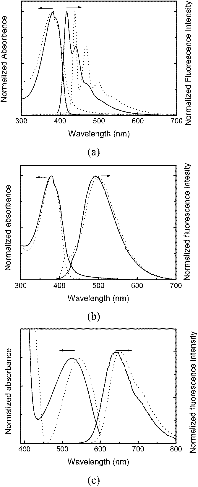 | ||
| Fig. 1 Absorption and emission spectra of (a) CP1 and bCPdot, (b) CP2 and gCPdot, and (c) CP3 and rCPdot. Excitation wavelength corresponds to the absorption maximum of each species. Solid line represents each polymer in chloroform solution and dotted line CPdots in aqueous solution. | ||
The fluorescence spectra of bCPdots (438 nm with shoulders at 466 nm and 498 nm) showed red-shifted emission compared with that of CP1 (417 nm with shoulders at 440 nm and 468 nm). gCPdots showed emission at 501 nm, and rCPdots at 652 nm. The fluorescence quantum yields of bCPdots, gCPdots, and rCPdots were 22%, 23%, and 18%, respectively, using rhodamine B as a reference. The sizes and shapes of CPdots were investigated with TEM and dynamic light scattering. Fig. 2 shows a TEM image of spherically-shaped gCPdots with a diameter of approximately 20 nm. Similar sizes of bCPdots and rCPdots were used for multi-emissive DoS and the size could be controlled by changing the concentration of the conjugated polymer solution.
 | ||
| Fig. 2 TEM image of gCPdots (scale bar 100 nm). | ||
The synthesis of green-emitting gDoS and Parg-encapsulated gDoS (Parg@gDoS) nanostructures is described in detail in the experimental section and a schematic illustration of the process is presented in Scheme 2 (right flow). To prepare silica particles, tetraethyl orthosilicate (TEOS) was reacted in the presence of ammonium hydroxide. Subsequently, the surface of silica nanoparticles was modified with (3-aminopropyl)triethoxysilane (APTES) to introduce positively charged amine-functionality on the silica to allow conjugation with CPdots. It is known that the CPdots are usually negatively charged,45 and thus by using this surface charge gCPdots can be conjugated onto the surface of APTES-modified silica nanoparticles via electrostatic interaction to form gDoS. Subsequently, Parg, which is a positively charged polypeptide, can encapsulate the negatively charged gDoS to form positive Parg@gDoS, which will show good cellular uptake efficiency.
 | ||
| Scheme 2 Schematic illustration of the preparation of Parg@gDoS and Parg@rgbDoS. | ||
Silica particles with a uniform size of about 180 nm were successfully prepared using a conventional method. Amine-modified silica particles were obtained using APTES.42,46 After APTES modification of the silica particles, the size and shape of the particles were not significantly altered, as shown in Fig. 3a. To verify whether amine groups had been introduced onto the particle surface, FT-IR spectroscopy was employed to characterize the presence of amine groups. After APTES treatment, a characteristic band was observed at 3180 cm−1 and was assigned to N–H.
 | ||
| Fig. 3 SEM images of silica nanoparticles functionalized with APTES (a) and gDoS (b) and TEM images of gDoS (c) and (d). | ||
Meanwhile, a pre-prepared solution of gCPdots was used to immobilize the dots on silica particles via electrostatic interaction. Because of the amine functional group conferred by APTES, APTES-modified silica particles have a positive charge (zeta potential of +13 mV). Thus spontaneous immobilization of negative gCPdots (zeta potential of −37.3 mV) on the positive surface of the silica particles allowed the fabrication of gDoS via charge interaction, as shown in Fig. 3b–d. Judging from the “fused conjugation” between gCPdots and silica particles as indicated by the arrow in the TEM image (Fig. 3d), it is expected that the gDoS would be stable to physical agitation. The emission spectrum of gDoS shows broad and structureless emission with a maximum at 485 nm, which is blue-shifted compared with gCPdots (Fig. S1†). The TGA thermogram shown in Fig. S2† suggests that 5.45 mg g−1 gCPdots are embedded on silica particles.
To elucidate the driving force for the immobilization of CPdots onto the silica particles, additional experiments were conducted. We investigated whether the interaction was brought about by electrostatic interaction or by covalent bonding between aldehyde groups in the polymer backbone and amine groups of the APTES on silica particles. Here, rCPdots from CP3, which did not contain aldehyde groups, were immobilized onto the surface of the APTES-modified silica nanoparticles using the same method that was applied in gDoS. As shown in SEM and TEM images (Fig. S3†), rCPdots, which did not have any functional groups that would react with amine groups, were successfully embedded on silica nanoparticles to form rDoS, which implies that embedding of CPdots on silica nanoparticles was accomplished through electrostatic interactions, not by covalent bonding. The presence of sulfur in rDoS was investigated with X-ray dispersive analysis (EDAX) to determine whether the dots on silica particles were from the polymer nanoparticles themselves (Fig. S4†). The presence of sulfur in CP3 was confirmed by EDAX data, which means rDoS was well-established. Therefore, the size and chemical structure of CPdots did not affect the immobilization behavior because the larger rCPdots (approximately 40 nm) could be facilely embedded onto the surface of the silica particles. However, the densities of gCPdots and rCPdots on each silica particle varied according to the size of the dots, mainly because of electrostatic repulsion between the CPdots.
Subsequently, we examined immobilization of dots on silica particles that were not modified with APTES. The zeta potential of unmodified, pure silica particles was −30 mV. As expected, the negatively-charged gCPdots were not embedded on the unmodified silica nanoparticles (Fig. S5a†). To further verify the charge interaction, a poly(styrene-co-divinylbenzene)-based anion (with NR3+ groups) and cation (with SO3− groups) exchange resins were used as substrates to immobilize bCPdots. The bCPdots were successfully immobilized onto anion exchange resins without any deformation of spherical shape (Fig. S5b†), but not onto cation exchange resins (image not shown). Based on these considerations, we conclude that the CPdots were introduced onto the silica surface via charge interaction.
Surprisingly, the interaction between gCPdots and silica particles was sufficiently stable to withstand sonication/centrifugation treatment, as shown in Fig. S6.† It clearly appeared that the stability of DoS was excellent even after repeated sonication/centrifugation cycles (each sonication time was 1 h). This result is encouraging because additional steps for protecting the CPdots are not required, leading to simpler procedure for the fabrication, compared to the previous report.41 gDoS was very stable in HEPES buffer at pH 7.4 for 5 days, showing no change in fluorescence intensity (Fig. S7a†). The photostability of gDoS solution compared with gCPdots solution and CP2 in chloroform solution was evaluated in HEPES buffer (pH 7.4) under a UV lamp (10 mW cm−2) for 30 min. As shown in Fig. S7b,† the fluorescence intensity from gDoS was constant, whereas other controls exhibited small extents of photobleaching. We concluded that the synthesized DoS was more stable to photoirradiation, buffer, and physical shear than its original components of polymer and resultant dots, mainly because of the immobilization to the robust silica support material.
After gDoS was fabricated, it was modified with a positively charged polypeptide to demonstrate its potential application to biological imaging. The positive polypeptide Parg was introduced onto the surface of gDoS, which had a negative charge (zeta potential −33.2 mV), to obtain Parg@gDoS via electrostatic interaction. The successful fabrication of Parg@gDoS was confirmed by changes in the hydrodynamic diameter (from 213 nm to 231 nm) and zeta potential (from −33.2 mV to +18.2 mV) and SEM and TEM images, as shown in Fig. 4 From these changes in size and surface charges, as well as from electron microscopy images, we confirmed that the uniform and secure Parg encapsulation of gDoS.
 | ||
| Fig. 4 (a) SEM and (b) TEM images of Parg@gDoS. Inset photo indicates the thickness of polyarginine layer. Scale bar for TEM 100 nm (inset 50 nm). | ||
Developing an effective technique to distinguish cancer cells from normal cells is challenging, and feasible detection can be accomplished by monitoring molecules, such as HER2 receptors, that are specifically overexpressed in cancer cells. To provide specificity for targeted cell imaging, the well-known interaction between a primary antibody and a cell surface receptor was exploited. Neu antibody was bound to the surface of Parg@gDoS by NHS-EDC chemistry, which involved the reaction between amino groups of Parg and carboxylic acid groups of the neu antibody, resulting in the formation of neu-Parg@gDoS. The neu antibody, which can specifically bind to HER2 receptors that are overexpressed in SKBR-3 breast cancer cells, was selected to demonstrate the ability of neu-Parg@gDoS to image target cells specifically.41,47,48
The cytotoxicity of neu-Parg@gDoS was evaluated by determining the metabolic viability of SKBR-3 breast cancer cells after incubation with different concentrations of neu-Parg@gDoS. Fig. 5 shows the cell viability after incubation with neu-Parg@gDoS at 0, 1, 5, 10, and 20 μL for 24 and 48 h, respectively. Cell viabilities of more than 90% were observed during the tested time, suggesting the low cytotoxicity of neu-Parg@gDoS. Such a low cytotoxicity of neu-Parg@gDoS is advantageous for its application in cell imaging. To investigate the ability of neu-Parg@gDoS to target cells, HER2-positive SKBR-3 breast cancer cells were used. SKBR-3 cancer cells were incubated with neu-Parg@gDoS and subsequently visualized with a confocal fluorescence microscope. SKBR-3 cancer cells incubated with neu-Parg@gDoS showed strong fluorescence after 2 h, indicating that neu-Parg@gDoS was present in the cytoplasm, as shown in Fig. 6 The confocal laser scanning microscopy (CLSM) images show that the fluorescence was intensified in the cytoplasm of the SKBR-3 cells. To confirm that the targeted uptake of neu-Parg@gDoS resulted from the neu antibody bound to the surface of Parg@gDoS, HER2-negative cancer cells were studied using MDA-MB-231 cells as a negative control. As expected, neu-Parg@gDoS was not internalized in the MDA-MB-231 cells because of the lack of HER2 expression (Fig. 7).
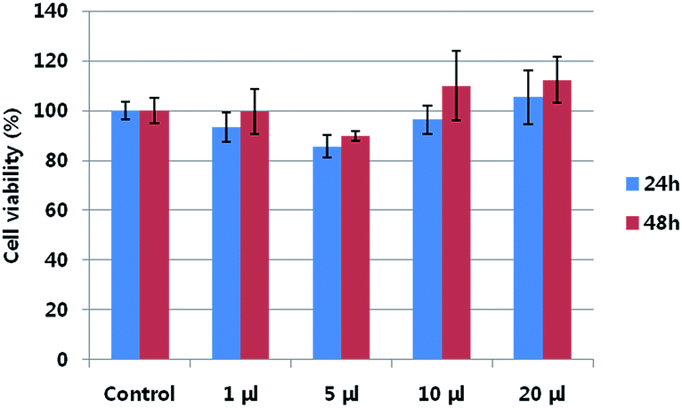 | ||
| Fig. 5 Metabolic viability of SKBR-3 breast cancer cell after incubation with neu-Parg@gDoS at various concentrations of neu-Parg@gDoS for 24 h (blue) and 48 h (red). | ||
 | ||
| Fig. 6 CLSM images of SKBR-3 breast cancer cells after 2, 6, and 24 h incubation with neu-Parg@gDoS. | ||
 | ||
| Fig. 7 CLSM images of MDA-MB-231 cells after incubation of 2, 6, and 24 h with neu-Parg@gDoS. | ||
The greater fluorescence intensity in SKBR-3 cells (Fig. 6) indicates that the neu antibody bound to the surface of Parg@gDoS promotes cellular uptake because of overexpressed HER2 on the cell membranes of SKBR-3 cells. By contrast, MDA-MB-231 cells exhibited weak fluorescence compared with SKBR-3 cells after incubation, even for 24 h, because the HER2 is not overexpressed in MDA-MB-231 cells. The intensity profiles of the cells were investigated to quantify the emission intensity of the cell uptake, in which higher intensity could be observed in the SKBR-3 cells (Fig. S9†). These findings suggest that our strategy for cell imaging using antigen–antibody interaction is successful.
In addition, silica particles were used for templating simultaneous multicolor CPdots using the process of immobilization as illustrated in Scheme 2 (left flow). In aqueous solution, rCPdots, gCPdots, and bCPdots were introduced to the surface of APTES-modified silica at the same time to obtain rgbDoS. The mixture of rCPdot, gCPdot, and bCPdot solutions with a volume ratio of 1:1:1 was used for equal emission intensity. The emission spectrum of rgbDoS shows emission maxima for bCPdots at 436 nm, gCPdots at 501 nm, and rCPdots at 645 nm, when excited at 380 nm, as shown in Fig. S8.† An SEM image of rgbDoS is not shown here because the individual CPdots cannot be discriminated by size. Upon excitation of rgbDoS at a short wavelength (380 nm), the blue-emissive CPdots (bCPdots) possibly act as an energy donor for longer-wavelength-emissive acceptors (gCPdots and rCPdots) through multistep FRET. However, multistep FRET did not occur, mainly because each CPdot was sufficiently isolated spatially to prevent mutual energy transfer. This results from the repulsive force between CPdots, which facilitated their spatial isolation on the surface of silica during immobilization.
Thus, the intensity of red emission of rgbDoS when excited at the absorption of rCPdots (540 nm) is similar to that excited at the shorter wavelength of 380 nm, thus the energy transfer can be concluded as being negligible, as shown in Fig. S8.† The silica particles play a role in templating to prevent FRET. This inhibited energy transfer cannot be attained using the previous method, because random mixing of three colored-CPdots may take place during the formation of silica particles, leading to spontaneous energy transfer.41
Because of the forbidden energy transfer between CPdots on the surface of silica, multicolor cell imaging was conducted using a single excitation source. The rgbDoS was treated with Parg to obtain Parg@rgbDoS, which allowed simultaneous multicolor cell imaging. Parg@rgbDoS could localize in the cytoplasm of HeLa cells through endocytosis when Parg@rgbDoS was bound to the surface of the cells by nonspecific interaction. Once neu antibody is conjugated to Parg@rgbDoS, specific cell imaging will also be possible.
To monitor cellular uptake, the rCPdot signal (red color), gCPdot signal (green color), and bCPdot signal (blue color) were recorded with a single excitation (360 nm) but different emission filter sets. As shown in Fig. 8, multicolor Parg@rgbDoS across the entire visible emission region was observed from each channel using a single excitation laser source. That the RGB fluorescence is from the same cytoplasm source was confirmed from each RGB channel at the same position. By comparison with cell imaging using a single emission color by single excitation, prevention of autofluorescence and precise positioning of multicolored images could be achieved using a simultaneous multicolor recognition approach. The spatial positioning of nanoscopic materials to submicroscopic silica substrates is a special technique with remarkable potential applications in photonics, electronics, and biotechnology.
 | ||
| Fig. 8 Confocal fluorescence images of Hela cells after 6 h incubation with Parg@rgbDoS through each RGB channel (excitation wavelength 360 nm). | ||
3. Conclusion
We have developed a new strategy to embed CPdots with various emission colors on silica particles (DoS). The gCPdots can be facilely immobilized on the surface of APTES-modified silica particles via electrostatic interaction. The resultant green-emitting gDoS was encapsulated using positively charged Parg to obtain Parg@gDoS, followed by a reaction with neu antibody to demonstrate efficient and specific targeted cell imaging using the newly designed DoS system. The conjugation approach through an amide linkage between carboxylic acid in the neu antibody and amine in functionalized Parg@gDoS is effective and can be applied to conjugation with biomolecules in a versatile manner. The obtained gDoS shows good stability toward light irradiation, buffer, and mechanical agitation. The neu-Parg@gDoS exhibits low cytotoxicity and realizes targeted imaging in SKBR-3 breast cancer cells, where HER2 receptors recognized by neu antibody are overexpressed. The post-decoration method can be expanded to immobilize different sizes of CPdots on silica spheres simultaneously by simple immersion of silica particles in the solution of mixed CPdots with the same or different sizes. A multicolor DoS that exhibits the entire visible emissions of red, green, and blue (rgbDoS) can be fabricated by simultaneous immobilization of rCPdots, gCPdots, and bCPdots, and shows multicolor cell imaging upon illumination by a single excitation source. The limited energy transfer between CPdots with different colors comes from the spatial isolation of CPdots with sufficient distance to prevent energy transfer, resulting in simultaneous red, green, and blue colored-cell imaging under a single source excitation. This newly developed “all-in-one” strategy has potential advantages over conventional single color imaging in the field of multicolor target imaging as well as multicolor cell detection. Moreover, this approach can prevent self-aggregation of nanoparticles and thus, can maintain the original fluorescence of nanoparticles with good colloidal and photochemical stability.4. Experimental
Materials
4-(Bis(4-bromophenyl)amino)benzaldehyde and 4,7-bis(5-bromothiophen-2-yl)benzo-2,1,3-thiadiazole were synthesized using published methods.49–53 9,9-dioctyl-2,7-dibromofluorene, 9,9-dioctylfluorene-2,7-diboronic acid bis(1,3-propanediol)ester, and tetrakis(triphenylphosphine)-palladium(0) were purchased from Sigma-Aldrich (St. Louis, MO, USA) and used as received. TEOS and APTES were purchased from Sigma-Aldrich and used without further purification. Anion (Trilite SAR10) and cation (Trilite SCR04) exchange resins with a diameter >0.40 mm were kindly supplied by Samyang Corp. (Seoul, Korea). Neu antibody (C-18) was purchased from Santa Cruz Biotechnology (Santa Cruz, CA, USA).Characterization
UV-vis absorption spectra were recorded on a Perkin Elmer Lambda 35 spectrometer. The photoluminescence spectra were taken using a Varian Cary Eclipse spectrophotometer equipped with a xenon lamp excitation source. The 1H and 13C NMR spectra were obtained on a Bruker DRX-300 spectrometer (Korea Basic Science Institute). Elemental analysis was performed with a CE Instruments EA-1110 elemental analyzer. The FT-IR spectra were recorded on a Bruker Tensor 27 spectrometer. The EDAX studies were performed on a JEOL JEM-210F HR. Fluorescence images of cells were collected on a DeltaVision PD. For TEM measurements, samples were prepared by drop-casting a 3 μL aliquot of the solution onto a carbon coated copper grid which was placed on a piece of paper to remove excess solvent. The thin films of green and red dots were dried for at least 6 h. The images were obtained on a JEOL JEM-3010 operating at 200 or 300 kV accelerating voltage, using the images acquired with an ORIUS-SC 600 CCD camera (Gatan, Warrendale, PA, USA).Synthesis of CP1
4-(Bis(4-bromophenyl)amino)benzaldehyde (0.022 g, 0.05 mmol), 9,9-dioctyl-2,7-dibromofluorene (0.521 g, 0.95 mmol), and 9,9-dioctylfluorene-2,7-diboronic acid bis(1,3-propanediol)ester (0.670 g, 1.2 mmol) were dissolved in a mixture of THF (10 mL), and 2 M aqueous K2CO3 solution (4 mL). After addition of tetrakis(triphenylphosphine)palladium(0) (3.5 mg, 0.003 mmol), the reaction mixture was stirred under argon at 100 °C for 48 h. After the reaction, the reaction mixture was cooled and slowly added to methanol (500 mL), and resulting precipitates were isolated by filtration. Then the precipitates were washed with methanol and extracted with acetone for 48 h in a Soxhlet apparatus to remove oligomers and catalyst residues (yield 0.51 g, 66%). 1H NMR (300 MHz, CDCl3) δ = 9.88 (s), 7.86–6.85 (m), 3.86–3.48 (m), 2.23–1.52 (m), 1.27–0.75 (m) ppm. 13C NMR (CDCl3): δ = 191.2, 152.0, 140.7, 140.3, 126.4, 121.7, 120.2, 77.7, 76.8, 70.8, 55.6, 32.0, 30.3, 24.1, 22.8 ppm. Anal. calcd for C51.6H76.5N0.1O0.1: C, 88.6%; H, 10.9%; N, 0.28%. Found: C, 87.9%; H, 10.0%; N, 0.30%. FT-IR (cm−1): 3030 (C–H), 1697 (C![[double bond, length as m-dash]](https://www.rsc.org/images/entities/char_e001.gif) O), 1591 (CC), 1462 (CC), 1320 (C–N).
O), 1591 (CC), 1462 (CC), 1320 (C–N).
Synthesis of CP2
4-(Bis(4-bromophenyl)amino)benzaldehyde (0.215 g, 0.50 mmol), 9,9-dioctyl-2,7-dibromofluorene (0.27 g, 0.50 mmol), and 9,9-dioctylfluorene-2,7-diboronic acid bis(1,3-propanediol)ester (0.67 g, 1.20 mmol) were dissolved in a mixture of THF (10 mL) and 2 M aqueous K2CO3 solution (4 mL). After addition of tetrakis(triphenylphosphine)palladium(0) (3.5 mg, 0.003 mmol), the reaction mixture was stirred under argon at 100 °C for 48 h. The reaction procedure is identical to that for CP1 (yield 0.42 g, 51%). 1H NMR (300 MHz, CDCl3) δ = 9.8 (s), 7.7–6.8 (m), 4.2–3.7 (m), 3.7–3.2 (m), 2.6–3.0 (m), 2.5–1.8 (m), 1.6–1.0 (m) ppm. 13C NMR (CDCl3): δ = 191.2, 146.7, 137.6, 133.1, 129.3, 128.4, 112.8, 51.2, 27.9 ppm. Anal. calcd for C50.4H69.0N0.4O0.4: C, 88.2%; H, 10.1%; N, 0.85%. Found: C, 87.9%; H, 9.92%; N, 0.81%. FT-IR (cm−1): 3028 (C–H), 1698 (CHO), 1592 (CC), 1461 (CC), 1275 (C–N).
Synthesis of CP3
4,7-Bis(5-bromothiophen-2-yl)benzo-2,1,3-thiadiazole (0.14 g, 0.3 mmol), 9,9-dioctyl-2,7-dibromofluorene (0.38 g, 0.7 mmol), and 9,9-dioctylfluorene-2,7-diboronic acid bis(1,3-propanediol)ester (0.670 g, 1.2 mmol) were dissolved in a mixture of THF (10 mL), and 2 M aqueous K2CO3 solution (4 mL). After addition of tetrakis(triphenylphosphine)palladium(0) (3.5 mg, 0.003 mmol), the reaction mixture was stirred under argon at 100 °C for 48 h. The reaction procedure is identical to that for CP1 (yield 0.56 g, 76%). 1H NMR (300 MHz, CDCl3) δ = 8.20–6.92 (m), 2.81–2.14 (m), 1.60–1.27 (m), 1.14–0.80 (m) ppm. 13C NMR (CDCl3): δ = 148.2, 140.7, 133.1, 128.4, 77.3, 76.7, 51.2, 31.8, 30.0, 22.6, 14.1 ppm. Anal. calcd for C51.5H67.4N0.86S1.29: C, 83.7%; H, 9.12%; N, 1.64%; S, 5.67%. Found: C, 83.7%; H, 9.30%; N, 1.58%; S, 5.55%. FT-IR (cm−1): 3025 (C–H), 1594 (CC), 1461 (CC), 1258 (C–N).
Preparation of CPdots
Fluorescent CPdots in aqueous solution were prepared by using a reprecipitation method.45 All procedures were performed at an ambient temperature. Typically, conjugated polymer was dissolved in THF to obtain a 1 mg mL−1 stock solution. The 1 mL quantity of the polymer solution was quickly added to MilliQ water (10 mL) in a vigorous bath sonicator, followed by removal of THF by nitrogen stripping. Then the solution was filtered using a 0.20 μm syringe filter. The conjugated polymer nanoparticle dispersions were directly used in the DoS fabrication step. Blue-emitting bCPdots, green-emitting gCPdots, and red-emitting rCPdots were prepared from CP1, CP2, and CP3, respectively.Preparation of silica particles functionalized with APTES
TEOS (1 mL) was added to ethanol (10 mL) under sonication. After 5 min, 25% aqueous ammonium hydroxide solution (10 mL) and ethanol (10 mL) were added to the mixture. Sonication was continued for a further 50 min to obtain a turbid white suspension. Then the reaction mixture was centrifuged to obtain silica particles. The separated silica particles were washed with water and ethanol. Then, the silica particles (1 g) were reacted with APTES (2 wt% with respect to silica particles) at 130 °C for 1 h. After the reaction, the silica particles functionalized with APTES were washed with water and methanol, repeatedly. Finally, the silica nanoparticles functionalized with APTES were isolated by centrifugation and dried in a vacuum oven.Fabrication of green-emitting gDoS
The stock solution of APTES-modified silica particles was prepared at a concentration of 5.0 mg mL−1 in water. The silica particle solution was added into the pre-prepared aqueous dispersion (10 mL) of gCPdots in a bath sonicator for 4 h. Then the prepared gDoS was isolated by centrifugation and washed with water three times. The obtained gDoS dispersion was stored at an ambient temperature.Preparation of red-, green-, and blue-emitting rgbDoS
A stock solution of the APTES-modified silica particles was prepared at a concentration of 5.0 g mL−1 in water. Then the solution (1 mL) of the silica particles was added to a mixture of rCPdots, gCPdots, and bCPdots (1:1:1, v/v/v) solution (9 mL) in a bath sonicator. After a period of 4 h, the rgbDoS was isolated by centrifugation, washed with water three times, and dried at an ambient temperature.
Introduction of Parg onto gDoS (Parg@gDoS) and onto rgbDoS (Parg@rgbDoS)
A stock solution of Parg (1 mg mL−1) was prepared. Then, added the Parg solution (2 mL) was added to a pre-prepared aqueous dispersion of gDoS (8 mL) in a bath sonicator. After a period of 2 h, Parg@gDos was collected by centrifugation and washed with water repeatedly. The fabrication procedure for Parg@rgbDoS is the same as that used for Parg@gDoS.Conjugation of neu antibody to Parg@gDoS (neu-Parg@gDoS)
1-Ethyl-3-(3-dimethylaminopropyl)carbodiimide hydrochloride (EDC, 40 mg) and N-hydroxysuccinimide (NHS, 9.7 mg) were dissolved in water (4 mL) by stirring for 10 min. Subsequently, neu (C-18) antibody was added to the solution and stirred mildly for 2 h. Then, the solution was injected into an aqueous dispersion of Parg@gDoS (5 mL). After a reaction time of 4 h, the mixture was collected by centrifugation and washed with water twice.Cellular uptake of neu-Parg@gDoS
To determine intracellular delivery of the neu-Parg@gDoS, SKBR-3 cells and MDA-MB-231 cells were incubated with neu-Parg@gDoS (20 μL per well) in a μ-slide 8-well microscopy chamber at a density of 5 × 10⁴ cells per well for 2, 6, or 24 hours at 37 °C. The cells were then washed in cold PBS and fixed with 4% (w/v) paraformaldehyde solution for 20 min at room temperature. Fluorescence images were obtained using a DeltaVision PD (Applied Precision Technologies, Issaquah, WA, USA) fitted with an appropriate filter set (DAPI: excitation 360/40 nm, emission 455/50 nm, and FITC: excitation 490/20 nm, emission 525/36 nm; Omega Optical, Brattleboro, VT, USA).Cellular uptake of Parg@rgbDoS
To determine intracellular delivery of the Parg@rgbDoS, HeLa cells were incubated with Parg@rgbDoS (20 μL per each well) in a μ-slide 8-well microscopy chamber at a density of 5 × 10³ cells per well for 6 hours at 37 °C. The cells were then washed in cold PBS and fixed with 4% (w/v) paraformaldehyde solution for 20 min at room temperature. Fluorescence images were obtained using a DeltaVision PD (Applied Precision Technologies) fitted with an appropriate filter set (DAPI: excitation 360/40 nm, emission 455/50 nm, FITC: excitation 490/20 nm, emission 525/36 nm, and Cy-5: excitation 645/30 nm, emission 705/72 nm; Omega Optical).Acknowledgements
This research was supported by Basic Science Research Program (2012R1A2A2A01004979) through the National Research Foundation of Korea (NRF) funded by Korean government.Notes and references
- I. L. Medintz, H. T. Uyeda, E. R. Goldman and H. Mattoussi, Nat. Mater., 2005, 4, 435 CrossRef CAS PubMed.
- H. H. Gorris and O. S. Wolfbeis, Angew. Chem., Int. Ed., 2013, 52, 3584 CrossRef CAS PubMed.
- L. Zhu, W. Wu, M.-Q. Zhu, J. J. Han, J. K. Hurst and A. D. Q. Li, J. Am. Chem. Soc., 2007, 129, 3524 CrossRef CAS PubMed.
- W. Lu, Y. Z. Tan, K. L. Hu and X. G. Jiang, Int. J. Pharm., 2005, 295, 247 CrossRef CAS PubMed.
- A. M. Dennis, W. J. Rhee, D. Sotto, S. N. Dublin and G. Bao, ACS Nano, 2012, 6, 2917 CrossRef CAS PubMed.
- C. Wu, B. Bull, C. Szymanski, K. Christensen and J. McNeill, ACS Nano, 2008, 2, 2415 CrossRef CAS PubMed.
- X. Gao, W. Tao, W. Lu, Q. Zhang, Y. Zhang, X. Jiang and S. Fu, Biomaterials, 2006, 27, 3482 CrossRef CAS PubMed.
- A. Jatsch, E.-K. Schillinger, S. Schmid and P. Böauerle, J. Mater. Chem., 2010, 20, 3563 RSC.
- K. Jaskiewicz, A. Larsen, I. Lieberwirth, K. Koynov, W. Meier, G. Fytas, A. Kroeger and K. Landfester, Angew. Chem., Int. Ed., 2012, 51, 4613 CrossRef CAS PubMed.
- X. Zhang, J. Yu, Y. Rong, F. Ye, D. T. Chiu and K. Uvdal, Chem. Sci., 2013, 4, 2143 RSC.
- M. Haase and H. Schäfer, Angew. Chem., Int. Ed., 2011, 50, 5808 CrossRef CAS PubMed.
- S. Pihlasalo, J. Kirjavainen, P. Hänninen and H. Härmä, Anal. Chem., 2011, 83, 1163 CrossRef CAS PubMed.
- T. Chen, Y. Hu, Y. Cen, X. Chu and Y. Lu, J. Am. Chem. Soc., 2013, 135, 11595 CrossRef CAS PubMed.
- K. Landfester, Angew. Chem., Int. Ed., 2009, 48, 4488 CrossRef CAS PubMed.
- Y.-H. Chan, F. Ye, M. E. Gallina, X. Zhang, Y. Jin, I.-C. Wu and D. T. Chiu, J. Am. Chem. Soc., 2012, 134, 7309 CrossRef CAS PubMed.
- J. Pecher and S. Mecking, Chem. Rev., 2010, 110, 6260 CrossRef CAS PubMed.
- K. Li and B. Liu, J. Mater. Chem., 2012, 22, 1257 RSC.
- D. Tuncel and H. V. Demir, Nanoscale, 2010, 2, 484 RSC.
- C. Wu and D. T. Chiu, Angew. Chem., Int. Ed., 2013, 52, 3086 CrossRef CAS PubMed.
- L. H. Feng, C. L. Zhu, H. X. Yuan, L. B. Liu, F. T. Lv and S. Wang, Chem. Soc. Rev., 2013, 42, 6620 RSC.
- J. Noh, B.-J. Chae, B.-C. Ku and T. S. Lee, J. Polym. Sci., Part A: Polym. Chem., 2014, 52, 1898 CrossRef CAS PubMed.
- X. L. Feng, G. M. Yang, L. B. Liu, F. T. Lv, Q. Yang, S. Wang and D. B. Zhu, Adv. Mater., 2012, 24, 637 CrossRef CAS PubMed.
- I. L. Medintz, A. R. Clapp, H. Mattoussi, E. R. Goldman, B. Fisher and J. M. Mauro, Nat. Mater., 2003, 2, 630 CrossRef CAS PubMed.
- C. F. Wu, T. Schneider, M. Zeigler, J. B. Yu, P. G. Schiro, D. R. Burnham, J. McNeill and D. T. Chiu, J. Am. Chem. Soc., 2010, 132, 15410 CrossRef CAS PubMed.
- J. Yang, Y. Zhang, S. Gautam, L. Liu, J. Dey, W. Chen, R. P. Mason, C. A. Serrano, K. A. Schug and L. Tang, Proc. Natl. Acad. Sci. U. S. A., 2009, 106, 10086 CrossRef CAS PubMed.
- K. Li, R. Zhan, S.-S. Feng and B. Liu, Anal. Chem., 2011, 83, 2125 CrossRef CAS PubMed.
- L. Feng, L. Liu, F. Lv, G. C. Bazan and S. Wang, Adv. Mater., 2014, 26, 3926 CrossRef CAS PubMed.
- W. Hu, X. Lu, R. Jiang, Q. Fan, H. Zhao, W. Deng, L. Zhang, L. Huang and W. Huang, Chem. Commun., 2013, 49, 9012 RSC.
- B. Bao, N. Tao, D. Yang, L. Yuwen, L. Weng, Q. Fan, W. Huang and L. Wang, Chem. Commun., 2013, 49, 10623 RSC.
- K. H. Ku, M. P. Kim, K. Paek, J. M. Shin, S. Chung, S. G. Jang, W.-S. Chae, G.-R. Yi and B. J. Kim, Small, 2013, 9, 2667 CrossRef CAS PubMed.
- C.-L. Chang and H. S. Fogler, Langmuir, 1997, 13, 3295 CrossRef CAS.
- Y. Jin, S. Kannan, M. Wu and J. X. Zhao, Chem. Res. Toxicol., 2007, 20, 1126 CrossRef CAS PubMed.
- P. Cheben, F. D. Monte, D. J. Worsfold, D. J. Carlsson, C. P. Grover and J. D. Mackenzie, Nature, 2000, 408, 64 CrossRef CAS PubMed.
- I. I. Slowing, B. G. Trewyn, S. Giri and V. S.-Y. Lin, Adv. Funct. Mater., 2007, 17, 1225 CrossRef CAS PubMed.
- N. Atchison, W. Fan, D. D. Brewer, M. A. Arunagirinathan, B. J. Hering, S. Kumar, K. K. Papas, E. Kokkoli and M. Tsapatsis, Angew. Chem., Int. Ed., 2011, 50, 1617 CrossRef CAS PubMed.
- F. Mahtab, Y. Yu, J. W. Y. Lam, J. Liu, B. Zhang, P. Lu, X. Zhang and B. Z. Tang, Adv. Funct. Mater., 2011, 21, 1733 CrossRef CAS PubMed.
- I. Sokolov and S. Naik, Small, 2008, 4, 934 CrossRef CAS PubMed.
- S. Santra, D. Dutta, G. A. Walter and B. M. Moudgil, Technol. Cancer Res. Treat., 2005, 4, 593 CAS.
- X. Zhao, R. P. Bagwe and W. Tan, Adv. Mater., 2004, 16, 173 CrossRef CAS PubMed.
- S. Santra, K. Wang, R. Tapec and W. J. Tan, Biomed. Opt., 2001, 6, 160 CrossRef CAS PubMed.
- J. Geng, L. Jie, J. Liang, H. Shi and B. Liu, Nanoscale, 2013, 5, 8593 RSC.
- C. Wu, C. Szymanski and J. McNeill, Langmuir, 2006, 22, 2956 CrossRef CAS PubMed.
- C.-S. Lee, H. H. Chang, J. Jung, N. A. Lee, N. W. Song and B. H. Chung, Colloids Surf., B, 2012, 91, 219 CrossRef CAS PubMed.
- C. Wu, S. J. Hansen, Q. Hou, J. Yu, M. Zeigler, Y. Jin, D. R. Burnham, J. D. McNeill, J. M. Olson and D. T. Chiu, Angew. Chem., Int. Ed., 2011, 50, 3430 CrossRef CAS PubMed.
- K. L. Cheng, Microchem. J., 2006, 82, 119 CrossRef CAS PubMed.
- Y. He and X. Yu, Mater. Lett., 2007, 61, 2071 CrossRef CAS PubMed.
- K. Li, Y. Liu, K.-Y. Pu, S.-S. Feng, R. Zhan and B. Liu, Adv. Funct. Mater., 2011, 21, 287 CrossRef CAS PubMed.
- H. Nakajima, N. Mizuta, K. Sakaguchi, I. Fujiwara, A. Yoshimori, S. Takahashi, R. Takasawa and S. Tanuma, Breast Cancer, 2008, 15, 65 CrossRef PubMed.
- Z.-G. Zhang, K.-L. Zhang, G. Liu, C.-X. Zhu, K.-G. Neoh and E.-T. Kang, Macromolecules, 2009, 42, 3104 CrossRef CAS.
- N. Y. Kwon, D. Kim, G. Jang, J. H. Lee, J.-H. So, C.-H. Kim, T. H. Kim and T. S. Lee, ACS Appl. Mater. Interfaces, 2012, 4, 1429 CAS.
- J. H. Lee, D. G. Kim, N. Y. Kwon, G. S. Jang, J. H. Son, M. Lee, H.-J. Cho, H.-S. Kweon and T. S. Lee, J. Polym. Sci., Part A: Polym. Chem., 2011, 49, 138 CrossRef CAS PubMed.
- S. Seo, J. Kim, G. Jang, D. Kim and T. S. Lee, ACS Appl. Mater. Interfaces, 2014, 6, 918 CAS.
- D. Kim and T. S. Lee, Chem. Commun., 2014, 50, 5833 RSC.
Footnote |
| † Electronic supplementary information (ESI) available: Synthetic routes and properties of polymers, emission and TGA thermogram of gDoS, SEM and TEM images of DoS, stability of gDoS, and emission of rgbDoS. See DOI: 10.1039/c4ra08587f |
| This journal is © The Royal Society of Chemistry 2014 |