
 Open Access Article
 This Open Access Article is licensed under a
 Creative Commons Attribution 3.0 Unported Licence
In situ non-invasive Raman spectroscopic characterisation of succinic acid polymorphism during segmented flow crystallisation†
Anuradha R.
Pallipurath‡
a,
Pierre-Baptiste
Flandrin
a,
Lois E.
Wayment
abc,
Chick C.
Wilson
ab and
Karen
Robertson§
 *a
*a
aDepartment of Chemistry, University of Bath, Claverton Down, BA2 7AY, UK. E-mail: Karen.Robertson@nottingham.ac.uk
bCMAC Future Manufacturing Hub, University of Bath, Claverton Down, Bath BA2 7AY, UK
cDiamond Light Source, Harwell Campus, Didcot, Oxfordshire OX11 0DE, UK
First published on 18th October 2019
Abstract
The kinetically regulated automated input crystalliser for Raman spectroscopy (KRAIC-R) combines highly controlled crystallisation environments, via tri segmented flow, with non-invasive confocal Raman spectroscopy. Taking advantage of the highly reproducible crystallisation environment within a segmented flow crystalliser and the non-invasive nature of confocal spectroscopy, we are able to shine light on the nucleation and growth of Raman active polymorphic materials without inducing unrepresentative crystallisation events through our analysis technique. Using the KRAIC-R we have probed the nucleation and subsequent growth of succinic acid. Succinic acid typically crystallises as β-SA from solution-based crystallisation although some examples of a small proportion of α-SA have been reported in the β-SA product. Here we show that α-SA and β-SA nucleate concomitantly but undergo Ostwald ripening to a predominantly β-SA product.
 Karen Robertson | Karen Robertson completed her PhD in synthetic inorganic chemistry and materials science at Imperial College London in 2012. After an accidental year in the oil and gas industry she returned to academia for a PDRA at the University of Bath developing millifluidic flow crystallisers. In 2018 she was awarded an Anne McLaren Research Fellowship at the University of Nottingham in the faculty of engineering. Karen is interested in the self-assembly mechanism of materials, structure:property relationships and how flow technologies can be used to control and influence this. The main focus for Karen's research is developing flow crystallisation apparatus with integrated non-invasive structural analysis to control and monitor crystallisation processes in situ. |
Design, System, ApplicationWe present the optimisation of non-invasive Raman spectroscopy for the use in following the crystallisation profile of succinic acid. Raman spectroscopy has been previously used to great effect in the monitoring and optimisation of flow synthesis applications but has yet to be employed in flow crystallisation applications. The methodology presented is of great importance to the growing flow crystallisation community: both in realtime feedback control and uncovering self-assembly mechanisms. By coupling non-invasive analytical techniques with a tri-segmented flow environment (KRAIC-R), we have conquered the blocking issues which have plagued in situ Raman analysis of crystallisation events to date to uncover a polymorphic progression during the crystallisation of succinic acid in solution. The KRAIC-R is widely applicable to other Raman active crystallising (and non-crystalline) materials without the need for a potentially contaminating influence from SERS substrates. As Raman is sensitive to changes in molecular interactions, organic and organometallic systems can be followed throughout the self-assembly process. Using the integrated KRAIC-R, control over the self-assembling material can be exacted simultaneously with online analysis which does not affect the assembly process. Current design constraints regarding triggering data capture with passing slugs and permeation through reactor walls is highlighted and will be investigated further. |
Introduction
The surge of progress in the past 10 years towards continuous crystallisation both in academic and industrial laboratories has been fuelled by the benefits of continuous technologies.1 It significantly reduces the reactor space requirements and the carbon footprint of the process whilst offering a higher degree of control over the process, than traditional batch alternatives.2 This control enables us to further our understanding of crystallisation in environments which simultaneously are representative of industrial processing and minimise the effect of uncontrollable changes prevalent in small scale screening.3Continuous processing is heavily researched in the context of the pharmaceutical industry,4 however new methods of process analytical technology (PAT) must be employed due to the challenges of compatibility and timescales which flow environments can present. PAT can enable an understanding of what is happening during a process, it also allows direct feedback control to either account for potential process variability, inconsistencies in feedstock or facilitate high throughput design of experiments (DOE) optimisation. Traditional invasive PAT, where a probe is inserted into a crystalliser,5 can cause complications in both the fluid dynamics and crystallisation profile in continuous or flow crystallisation environments – e.g. the size of an immersion probe induces unwanted influence on the flow profile of the crystalliser and is prone to causing nucleation and growth on the probe.6 This alters the crystallisation profile, has a deleterious effect on the ability of the probe to representatively sample the crystallisation environment and ultimately leads to blockage and failure of the crystalliser.
In order to address these issues, non-invasive analytical techniques have been developed. Most notably, Raman spectroscopy, and in particular surface enhanced Raman spectroscopy (SERS), has been used to great effect in microfluidic environments as an analytical probe for solute concentration determination.7 By employing segmented flow with nanoparticles either pre-prepared8–10 or synthesised in flow,11,12 the detection limit of the Raman can be greatly enhanced whilst the use of segmented flow simultaneously ensures there is no poisoning of the SERS substrate and provides plug flow.13 This however requires the introduction of nanoparticles that can greatly affect a crystallising system. For this reason, analysis of crystallising solutions is not compatible with SERS.
Due to the complications of integrating Raman into crystallisation environments, previously published examples of exploring crystallisation processes through Raman spectroscopy have either used microscopy in static environments14–16 or immersion probes in batch,6,17–19 mixed suspension mixed product removal (MSMPR)5 and hot melt extrusion (HME)20 environments.
The authors have shown how a segmented flow kinetically regulated automated input crystalliser (KRAIC) can control the crystallisation of the excipient and food additive succinic acid (SA).21 SA is polymorphic and ordinarily observed as pure β-SA from solution-based crystallisation. Upon crystallisation within the KRAIC, some α-SA is present in the final product as observed through offline powder X-ray diffraction (PXRD). Only two other known examples of α-SA crystallising in solution environments are known – spray drying22 and in μ-capillaries of hydrophobic and hydrophilic, fluoroethylene propylene FEP15 – but the mechanism of this crystallisation is not yet understood.
Here we present for the first time, non-invasive Raman spectroscopic analysis of a crystallising system, using the benefits of segmented flow. We validate a SERS-free flow environment method through detection of alternating slurries of paracetamol (PCM) forms I and II and SA α and β. This method is then employed in a segmented flow crystalliser with isolation box fixtures at two points to monitor the crystallisation pathway of SA by confocal Raman spectroscopy, the kinetically regulated automated input crystalliser for Raman spectroscopy (KRAIC-R). Previous studies highlighted that solids were consistently observed at a specific reactor length (7 m) under the crystallisation conditions employed here. By probing shortly prior to this noted length (5 m) and near the end of the reactor (15 m), we can reliably follow the initial nucleation (R1) and subsequent growth (R2) of the crystals. By this method we evaluate whether the ratio between α- and β-SA changes over the crystalliser length, providing insight into the relationship between the polymorphs nucleation and crystal growth periods.
Experimental
Materials
Paracetamol (PCM) form I, β-succinic acid (β-SA) (99%), cyclohexane and isopropyl alcohol (IPA) were purchased from Sigma-Aldrich® and used without further purification. Perfluoropolyether (PFPE, GALDEN SV110) was sourced from Solvay.Crystallisation of polymorphs
PCM II was prepared by crystallisation in the continuous oscillatory baffle crystalliser (COBC) as previously published in the group.17 α-SA was prepared by melting of β-SA at 190 °C and confirmed by powder X-ray diffraction (PXRD), see Fig. S3.†Slurry preparation and set-up
Slurries for PCM FI (30 g l−1), PCM FII (30 g l−1), α-SA (200 g l−1) and β-SA (200 g l−1) were prepared in distilled water at room temperature to achieve high density of solids in the suspension. These slurries were used for initial testing and optimisation of the set-up. The slurry testing set-up comprised a cross-piece (3 mm, ID) – for segmentation of the slurry flow (3.4 ml min−1) by air (4.1 ml min−1) and a perfluoropolyether carrier fluid (PFPE, 2.1 ml min−1) – and a fluoroethylene propylene (FEP) tubing (1 m, 1/8′′ ID). At 0.7 m length of the FEP tubing, an isolation box composed of laser board housed the confocal Raman probe to minimise light interference and provide a flexible analytical environment.Continual delivery of all three phases was employed for single slurry delivery experiments using a low pulsation peristaltic pump (SF-10, Vapourtec) for slurry delivery and gear pumps (Ismatec Reglo ICC) for air and carrier fluid. Alternating slurry deliveries were achieved through the addition of a t-piece placed 1 cm after the cross-piece for the second slurry addition port. Due to the needle like habit of α-SA and the potential for β-SA to convert into α-SA upon grinding through the peristaltic pump, succinic acid slurries were delivered using syringes and hand agitation.
In situ crystallisation of SA in the KRAIC-R
Succinic acid (1.01 M solution in water) was crystallised in a KRAIC set-up, under segmented flow conditions with a cooling gradient of 40–20 °C over the 15 m length of the FEP tubing (1/8′′ ID) as described in our previous work.23 Flow rates and pump types employed are the same as those quoted in the slurry delivery section. The full residence time (RT) from the KRAIC-R is 12 min 34 s, Raman spectra are collected from the end of coil 1 (R1, 5 m, 4 min 12 s RT) and coil 3 (R2, 15 m, 12 min 0 s RT). Fig. 1a shows the schematic of the KRAIC set-up, and Fig. 1b shows the backscattering mode of the Raman data collection from the reactor at point R1 and R2. The cooling crystallisation of SA was run for a total of 20 min.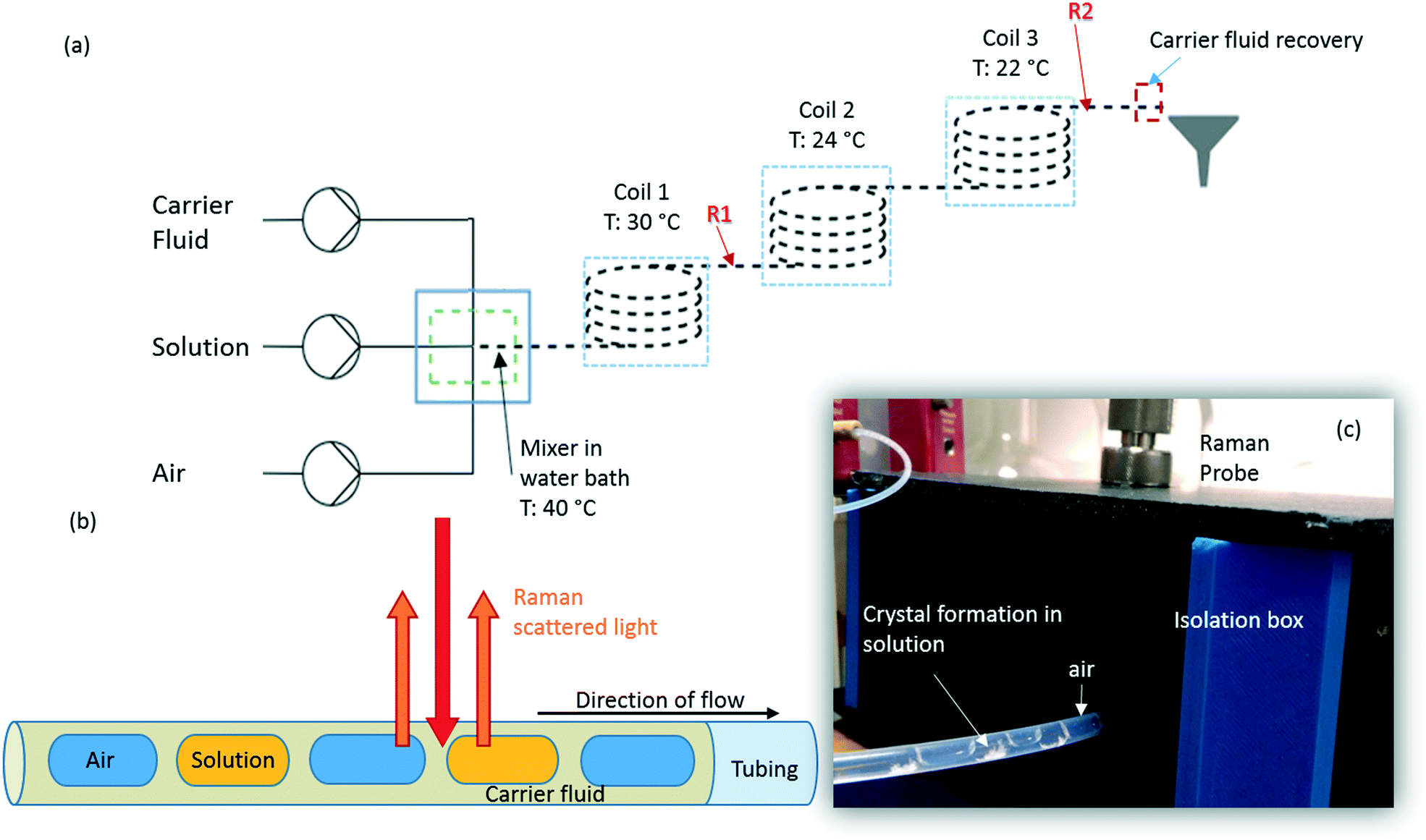 | ||
| Fig. 1 (a) Schematic of the kinetically regulated automated input crystalliser for Raman spectroscopy (KRAIC-R) flow set-up, where time dependent Raman spectra were collected from points labelled R1 and R2 (b) schematic of tri-segmented flow with the Raman scattering collected from the different segments. (c) The Raman set-up for slurry testing with the fibre-optic probe attached with an objective (10×), inside an isolation chamber through which the FEP reactor is introduced into the isolation box. | ||
Raman spectroscopy
Data collection
Raman spectra were collected using a 785 nm laser (400 mW power at source, 250 mW at sample) and KAISER RXN1 spectrometer with a fibre-optic set-up attached to an objective lens of 10× magnification. The fibre-glass probe is 3 m long, and is fitted with a filter to cut off the 1064 cm−1 band arising from glass. Best results were achieved with a working distance (WD) of 0.3′′ from the tubing, in the range of 100–3400 cm−1, with a resolution of 4 cm−1. Four scans were integrated and acquisition times of 15 s per scan and 500 ms for in situ crystallisation experiments, at points R1 and R2 respectively, and 250 ms for solid samples were used. The optimal WD was adjusted such that the FEP reactor tubing initially gives the highest Raman intensity. The WD is then reduced to move the focus from the top of the reactor to the middle of the tubing, facilitated by filling the tubing with cyclohexane. The presence of two holographic filters at 840 cm−1 and 2000 cm−1 results in discontinuity in the spectra in these regions and is highlighted during the analysis.An isolation box was used to exclude stray light and contain the region of interest along the tubing. Cosmic ray exclusion methods were not employed due to significantly increased data collection times. Initial dark scans are collected for the same measurement set-up as the actual scans to calibrate the detector. HoloGRAMS software v4.1 (Kaiser Optical Systems Inc.) was used to acquire data and to carry out dark current corrections for all spectra collected prior to further processing.
Data processing
Data processing was carried out using a modified version of the ‘Mayapy’ python code published elsewhere.24 Processing was carried out in three steps as follows:Step 1 – Spectra are smoothed with a 21-point triangle filter to improve the signal/noise (S/N) ratio.
Step 2 – The smoothed spectra can then be subjected to three different post-processing steps, either for the entire range of the spectrum or for the desired wavenumber range to enhance the S/N ratio of the peaks. The three processes are:
 | (1) |
Spectra can also be scaled relative to each other using the ‘scale_all’ algorithm. See ESI† for more details.
| IBS = Isolution − IFEP | (2) |
The effect of ‘scale_individual’ and ‘scale_all’ on the spectra can be seen in Fig. S1 in the ESI.†
Step 3 – 2D time-dependent spectra were plotted with a 500 point interpolation. To obtain the best results that represent the change in the Raman features the intensity of the scaled spectra was allowed to be ‘clipped’ at a certain value, in cases where background subtraction was not employed. Another method employed is the use of a linear or logarithmic colour scale to allow for distinction between low intensity bands.
To analyse the peak positions, the peak analyser algorithm in Origin Pro 9 v2019b (OriginLab®) was used.
Results and discussion
To optimise the implementation of non-invasive Raman spectroscopy into a tri-segmented flow crystallisation set-up, pre-prepared high density slurries of the polymorphs of PCM and SA were initially investigated in a short reactor set-up. Scheme 1 shows the molecular structures of the materials of interest and the FEP tubing used as the reactor body. Raman spectra of the solids were collected for reference (Fig. 2) and a full set of tentative assignments can be found in the ESI† (Tables S1–S3). As can be seen from Fig. 2a, the introduction of cyclohexane into the reactor (for WD positioning) results in a large fluorescence background, however, the major peaks can still be identified as that of FEP (denoted by the dotted lines). The FEP peaks denoted by * are absent in the spectra with cyclohexane flowing through the reactor, however, they are occasionally present in the aqueous-based flow experiments presented hereafter.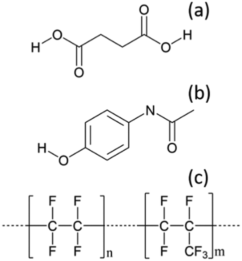 | ||
| Scheme 1 Molecular structures of (a) succinic acid (SA), (b) paracetamol (PCM), (c) the reactor tubing material – fluorinated ethylene propylene (FEP). | ||
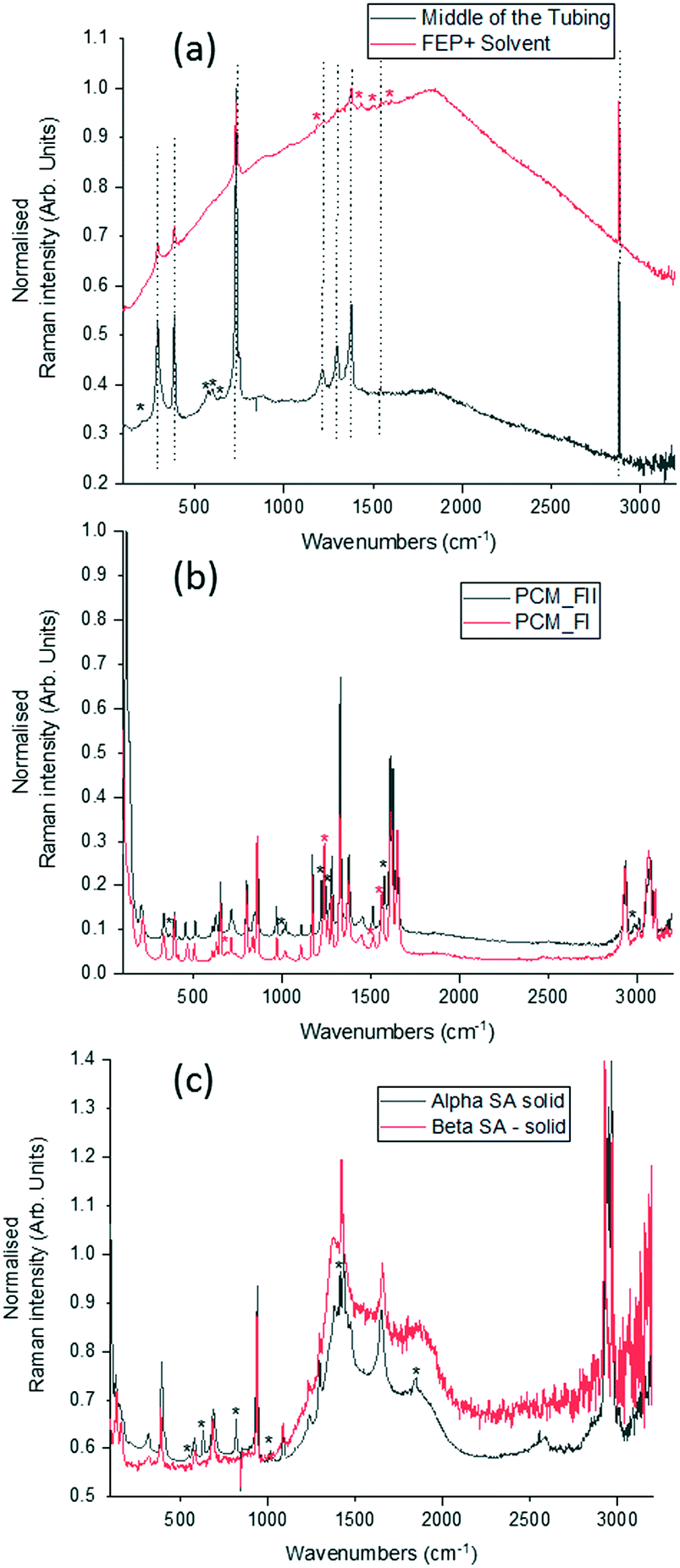 | ||
| Fig. 2 Raman spectra of (a) empty FEP tubing and tubing with cyclohexane. The dotted lines represent peaks belonging to FEP and the * denote FEP peaks that are absent on pumping cyclohexane through it. * denotes peaks associated with cyclohexane, (b) polymorphs of paracetamol in the solid-state, (c) polymorphs of succinic acid in the solid-state. Peaks unique to the specific polymorph in (b) and (c) are denoted by * and coloured based on the legend. | ||
Both PCM and SA have several peaks in the region of 500–1800 cm−1 that enable differentiation between the polymorphs in the solid state. While the C–H region (2800–3200 cm−1) does have subtle differences in the solid state for both PCM and SA, the peaks arising from FEP in the segmented flow set-up masks this region. It is noted that, the Raman scattering intensities of the analytes are weakened due to the increased fluorescence background as compared to the spectra from static solid-state samples.
Fig. 3 shows time-dependent Raman spectra from pre-prepared high density slurries of PCM FI followed by PCM FII. Initial data analysis used the ‘scale_all’ algorithm, which highlighted any inconsistencies in flow events but proved incompatible for polymorphic analysis. A full discussion of this is available in the ESI.†
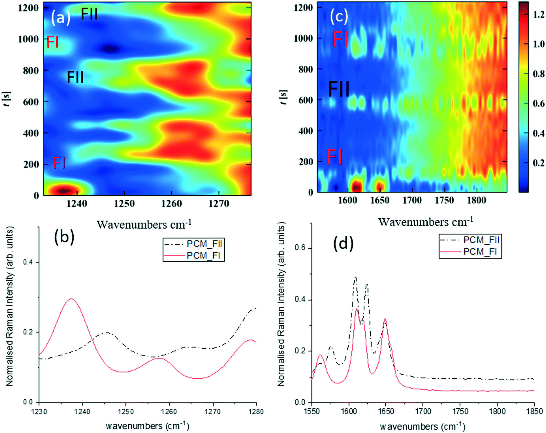 | ||
| Fig. 3 Time-dependent Raman spectra collected from alternating pre-prepared high density slurries of PCM FI and FII (injection point identifications highlighted on spectra). (a) 1200–1300 cm−1 regions of Raman spectra scaled individually, (b) corresponding 1D spectrum, (c) 1550–1850 cm−1 region of the Raman spectra scaled individually, (d) corresponding 1D spectrum. | ||
More specific information about the polymorphic nature of the slurry can be obtained by scaling the spectra individually in the region of interest and with the background comprising FEP subtracted from the spectra. Fig. 3a and c were obtained by treating the spectra using the ‘scale_individual’ algorithm in the regions of interest followed by the ‘background_subtraction’ algorithm. This method has been used for all other polymorphic investigations presented herein.
Whilst there are several peaks that distinguish between forms I and II for PCM, the most discernible amidst the FEP bands in solution are peaks at 1237 cm−1 for PCM FI and 1248 cm−1 for PCM FII arising from the C–O amide III band and the amide I C![[double bond, length as m-dash]](https://www.rsc.org/images/entities/char_e001.gif) O stretching between 1610 cm−1 and 1650 cm−1 as previously observed in the literature.25,26 To ensure that identification of polymorphs in flow environments was possible, PCM FI and FII were alternately injected into the segmentation set-up, this is reflected in the time resolved spectra shown in Fig. 3 (representative 1D plots are presented in the ESI,† Fig. S4).
O stretching between 1610 cm−1 and 1650 cm−1 as previously observed in the literature.25,26 To ensure that identification of polymorphs in flow environments was possible, PCM FI and FII were alternately injected into the segmentation set-up, this is reflected in the time resolved spectra shown in Fig. 3 (representative 1D plots are presented in the ESI,† Fig. S4).
Single streams of α-SA and β-SA slurries were also analysed. α-SA and β-SA have very similar crystal structures and hence very similar vibrational features. In addition to subtle differences in peak positions, α-SA has extra peaks at 628 cm−1, 814 cm−1 and 1020 cm−1 that are absent in β-SA, corresponding to different C–O and O–H H-bonded interactions (ESI† Table S2). Initial Raman analysis of the α-SA slurry confirmed the presence of α-SA in the tri-segmented flow environment. Extended analysis at 0.7 m crystalliser length however uncovers conversion of α-SA to β-SA as a factor of run time. Fig. 4 shows the time-resolved Raman spectra from three regions: 500–700 cm−1, 780–1120 cm−1 and 1400–1850 cm−1. The conversion is most apparent in the regions of 780–1120 cm−1 and 1400–1850 cm−1. The conversion of the α-SA prepared slurry is presumed due to the higher stability of β-SA in aqueous solutions. This crystallisation of small amounts of α-SA have previously been observed during spray drying and crystallisation in static FEP tubing.15,22
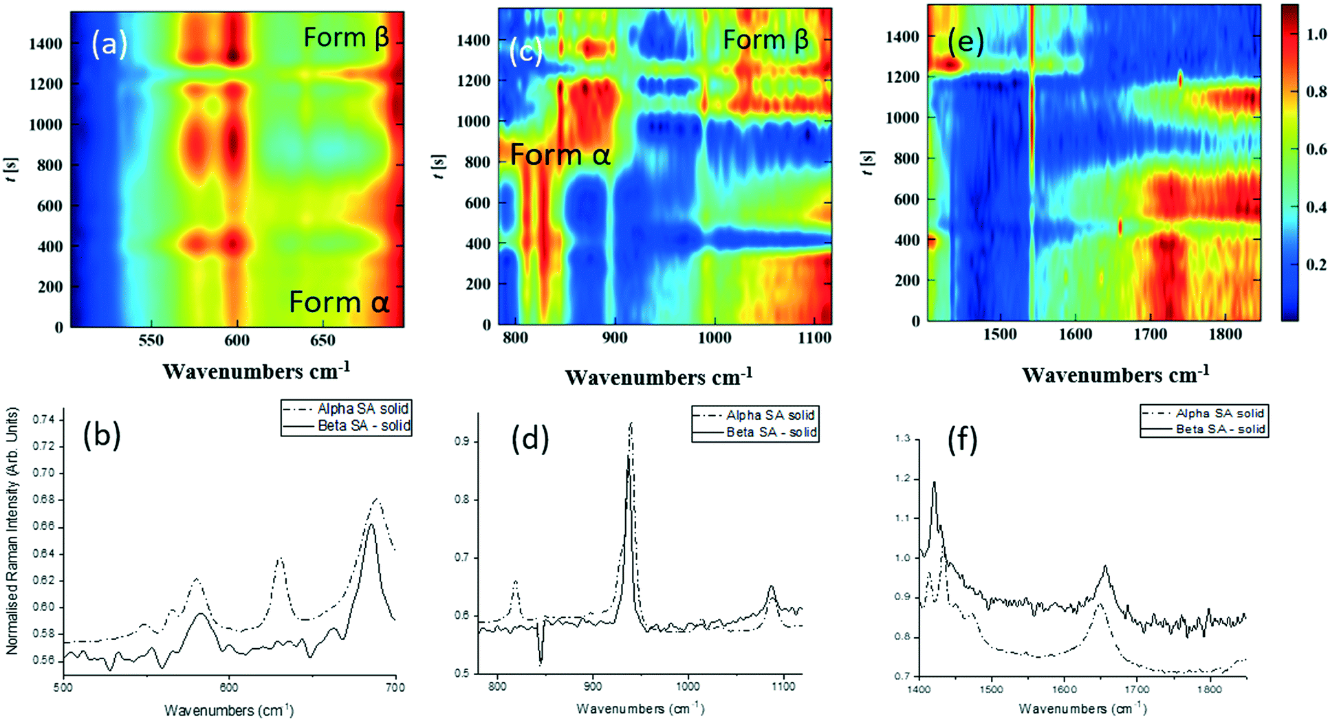 | ||
| Fig. 4 Time-dependent Raman spectra collected from pre-prepared high density slurry of succinic acid form α. In the region of (a) 500–700 cm−1, (b) corresponding 1D spectrum (c) 780–1120 cm−1, (d) corresponding 1D spectrum (e) 1400–1850 cm−1, (f) corresponding 1D spectrum. The regions of interest were scaled individually, to enhance the Raman peaks from the solids flowing through. | ||
Analysis of a β-SA slurry in a tri-segmented flow environment confirmed the presence of pure β-SA throughout the analysis period (see ESI† Fig. S2).
The white box in Fig. 4e highlights a peak from both solid forms that is absent in the slurry sample. This is a result of the background subtraction that removes FEP peaks in that region of the spectrum. During peak assignment in the slurry, it was observed that the monomeric C–O present in the solid phase for α-SA at 931, 940, 1014 and 1088 cm−1, shifted to lower wavenumbers (827, 894, 992 cm−1), showing a C–O H-bonding interaction with water. Similarly, for β-SA experiments, the C–O monomeric stretching was found to have shifted to lower wavenumbers (from 963, 983, 1035 and 1086 cm−1 to 830, 857, 895, 927 and 939 cm−1).
Crystallisation of succinic acid in the KRAIC-R
In previous publications of crystallisations in the KRAIC,21,27 we noted the production of unexpected polymorphs from aqueous-based crystallisation. In the case of pyrazinamide (PYZ), pure γ-PYZ was produced unless blockages were encountered during crystallisation, in which case the expected α-PYZ was also obtained.27 In SA crystallisation, small impurities of α-SA were found present in the expected β-SA product.21 We have hypothesised that the absence of a liquid–solid boundary (due to the tri-segmented flow environment) during nucleation has resulted in this unusual polymorphism, although recent results from Simone et al. show that a small amount of α-SA can form from solution-based crystallisation within FEP tubing (both hydrophilic and hydrophobic) without a carrier fluid barrier.15In order to investigate whether preferential crystallisation of β-SA is instigated from the nucleation phase or whether a conversion occurs during the growth phase, time-dependent Raman spectra were collected from points R1 and R2 (5 m and 15 m) in the KRAIC-R during a cooling crystallisation experiment. Previous studies highlighted that solids were consistently observed from 7 m reactor length under these crystallisation conditions; nuclei can therefore be expected to form around 5 m whilst 15 m represents full growth in this system.
As detailed in Table 1, data collection was taken from 3–10 min crystallisation time at point of analysis for R1 and 3–8 min for R2 (7–14 min and 15–20 min respectively in experiment time, taken from RT = 0). N.B. these sampling times mean we that we could have followed the crystallisation of the same set of solution slugs over the course of their crystallisation profile by analysing them at two different lengths scales and corresponding time points. A detailed analysis of the regions between 500–700 cm−1, 780–1120 cm−1 and 1400–1800 cm−1 (Fig. 5) reveals an interesting mechanism. Forms α and β have very similar features in the region of 500–700 cm−1 (Fig. 5(a–c)), but comparing peaks in the region of 780–1120 cm−1 (Fig. 5(d–f)), at R1 and R2 shows a continuous presence of peaks from both α-SA and β-SA during all stages of crystallisation. In spectra analysed from R1, a high proportion of α-SA can be discerned throughout the entire analysis time. Analysis of the spectra obtained at R2 however shows a decrease in the proportion of α-SA observed, with respect to β-SA, over the duration of the crystallisation run.
| R1 | R2 | |
|---|---|---|
| Length (m) | 5 | 15 |
| RT (min) | 4.2 | 12 |
| Analysis time (min) | 0–7 | 0–5 |
| Crystallisation time (min) | 3–10 | 3–8 |
| Experiment time (min) | 7–14 | 15–20 |
| Exposure time (s) | 15 | 0.5 |
| No. integrations | 4 | 4 |
| Delay (s) | 0 | 2 |
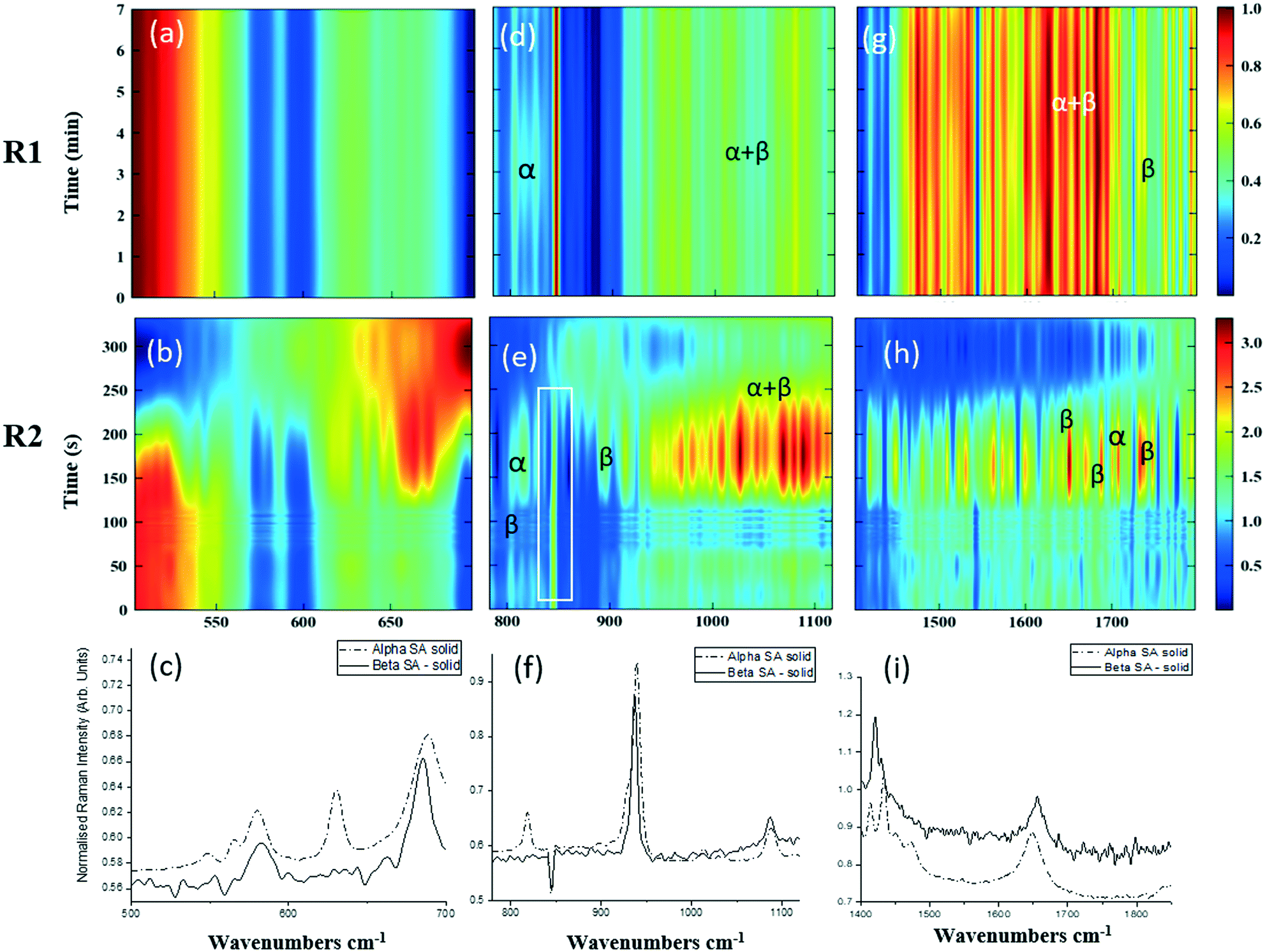 | ||
| Fig. 5 Time-dependent scaled Raman spectra collected from crystallisation of SA in the KRAIC-R, under segmented flow conditions, from points R1 and R2 as described in Fig. 1 and 1D plots from solid samples. (a–c) 500–700 cm−1 (d–f) 780–1120 cm−1 (g–i) 1400–1850 cm−1. The white boxes in (d) and (e) show an artefact that arises from the combination of discontinuity from the change in holographic filters followed by background correction. | ||
In the early crystallisation period after priming, a dilution effect from laminar flow within the feed tube (upon changing from priming to feed solution, initial 70 s analysis time) is in effect. The reduced concentration of SA effected by this dilution in the early stages of the experiment will therefore result in crystallisation farther along the crystalliser length. At R2 we observe the presence of both α-SA and β-SA, whose intensities both increase with time (Fig. 5(b), (e) and (h)). Peaks from α-SA can be found in high proportion between 0–50 s (analysis time) interval, along with β-SA. Between 150–200 s, the Raman intensities are predominantly from β-SA although some α-SA can be discerned, as shown in Fig. 5.
Minor contributions from form α can be discerned in the spectra from 150 s analysis time but only as a consequence of multiple C–O⋯O interactions that are very similar in both α-SA and β-SA. Powder X-ray diffraction data (Fig. S3, ESI†) confirms the presence of very small amounts of α-SA remaining in the final sample collected. This change in α-SA![[thin space (1/6-em)]](https://www.rsc.org/images/entities/char_2009.gif) :β-SA, both due to dilution and between the early nucleation stage (R1) and late growth (R2), suggests that both forms nucleate concomitantly but, as observed in the case of pre-prepared slurries, α-SA subsequently undergoes ‘Ostwald ripening’ and converts to β-SA.
:β-SA, both due to dilution and between the early nucleation stage (R1) and late growth (R2), suggests that both forms nucleate concomitantly but, as observed in the case of pre-prepared slurries, α-SA subsequently undergoes ‘Ostwald ripening’ and converts to β-SA.
Discussion of Raman monitoring
To understand the time-resolved Raman spectra, it is imperative to understand the flow conditions of the segmented flow reactor. Segmentation of water and air in the carrier fluid via the 3 mm ID cross-piece resulted in slugs that were 1.8 cm long. Under the described flow conditions the frequency of slugs passing under the Raman probe was ∼18 slugs per min. Using a solvent with a lower surface tension, such as isopropanol, or alternative segmentation piece with narrower internal dimensions, will result in slug sizes that are significantly shorter.Several data collection strategies were investigated including varying number of scans and integration times. A scan of 30 s with one acquisition resulted in a saturated detector, while 15 s exposures with four integrated scans gave the best results for low intensity spectra from R1 and 500 ms exposures with four integrated scans gave the best results from the relatively high intensity spectra from R2. This discrepancy of spectra intensity obtained between R1 and R2 is directly attributable to the amount of crystallisation at each analysis point. Each integrated scan collects data from roughly four slugs, two of the solution and two of air. Due to the steady-state nature of flow crystallisation, this relatively lengthy acquisition time with respect to that achieved in SERS applications is not a significant drawback. Although for high-throughput applications, further optimisation of the acquisition time would be necessary. The initial lower intensity of the Raman peaks observed at R2 can be attributed to the dilution effect previously discussed, while the perceived gaps in Fig. 5e, from lower Raman intensity can be attributed to the several eventualities: a) the observed rate of crystallisation might not be uniform in every solution segment; b) the eddies that result in the tumbling of the crystals at the end of the every slug, may force the crystals out of focus (i.e. not in the middle of the tube), whilst passing under the probe or c) the scan rate results in non-uniform collection of solution slugs. This final point can be explained through a scan rate of 4 s per data collection of slugs moving at 18 slugs per min under the probe, the data acquisition time resulting probing 0.6 slugs every measurement; random fluctuations in either data acquisition start point or air and solution slug length could lead to most of the data collection during the low intensity regime, being collected from air slugs, while only catching small (low crystal slurry density portions) of a solution slug.
Future avenues for opportunity would be to employ spatially offset Raman spectroscopy (SORS),28 which would allow spectra to be obtained without the masking effect of the reactor wall, as well as synchronising the flow and the data collection regimes.
Conclusion
We have developed a non-invasive, online monitoring system for tracking polymorphic changes occurring in segmented flow crystallisation using Raman spectroscopy. This method has been validated through both slurry flow (PCM and SA) and cooling crystallisation (SA) operation.Using several post-processing methods we can track regions of high and low Raman intensity thereby tracking the flow of slugs and identify inconsistencies in flow and crystallisation conditions. By processing selective regions of the Raman spectra we can follow polymorphic transformations occurring during crystallisation.
During Raman analysis of delivery of a pre-prepared α-SA slurry, a polymorphic transformation from α-SA to β-A was found to occur over time.
In a cooling crystallisation experiment, α- and β-SA were found to nucleate concomitantly during the initial stages of crystallisation. The metastable form, α, was then found to partially transform to β-SA along the reactor length. The final collected product was shown to be predominantly β-SA with a minor fraction of α-SA, as confirmed by powder X-ray diffraction. Due to the nature of flow crystallisation, we were able to follow the crystallisation of the same crystals in a highly controlled environment at different points of their crystallisation profile.
The methodology presented here for non-invasive Raman spectroscopic analysis of an actively crystallising material in flow environments, presents an opportunity to uncover the crystallisation profile of a wide range of crystalline material from the nucleation stage through crystal growth. The integration of Raman spectroscopy into flow crystallisation apparatus enables rigorous analysis of crystallisation events in a highly reproducible environment, simultaneously representative of industrial processing and accessible at academic lab scale.
Conflicts of interest
The authors declare no conflict of interest.Acknowledgements
The authors would like to thank Clairet Scientific Ltd. for the loan of the Kaiser RXN1 to carry out the experiments and Dr John Andrews for continued technical support. We would also like to thank Dr Jonathan Skelton for modifying python scripts to improve data analysis and Vapourtec UK for loan of the SF-10 low pulsation peristaltic pump required for slurry delivery. This work was funded by the Metastable Materials programme grant (No. EP/K004956/1, A. Pallipurath, P.-B. Flandrin, K. Robertson), the CMAC future manufacturing hub (EP/P006965/1, C. C. Wilson, L. Wayment) and Diamond Light Source (L. Wayment).References
-
P. Kleinebudde, J. Khinast and J. Rantanen, Continuous Manufacturing of Pharmaceuticals, Wiley, 2017 Search PubMed
.
- Z. K. Nagy and R. D. Braatz, Advances and New Directions in Crystallization Control, Annu. Rev. Chem. Biomol. Eng., 2012, 3(3), 55–75 CrossRef CAS PubMed
- G. S. Calabrese and S. Pissavini, From Batch to Continuous Flow Processing in Chemicals Manufacturing, AIChE J., 2011, 57(4), 828–834 CrossRef CAS
- D. J. Zhang,
et al., Progress of Pharmaceutical Continuous Crystallization, Engineering, 2017, 3(3), 354–364 CrossRef
- K. A. Powell,
et al., Monitoring Continuous Crystallization of Paracetamol in the Presence of an Additive Using an Integrated PAT Array and Multivariate Methods, Org. Process Res. Dev., 2016, 20(3), 626–636 CrossRef CAS
- D. Acevedo,
et al., Raman Spectroscopy for Monitoring the Continuous Crystallization of Carbamazepine, Org. Process Res. Dev., 2018, 22(2), 156–165 CrossRef CAS
- I. J. Jahn,
et al., Surface-enhanced Raman spectroscopy and microfluidic platforms: challenges, solutions and potential applications, Analyst, 2017, 142(7), 1022–1047 RSC
- B. D. Piorek,
et al., Discrete Free-Surface Millifluidics for Rapid Capture and Analysis of Airborne Molecules Using Surface-Enhanced Raman Spectroscopy, Anal. Chem., 2014, 86(2), 1061–1066 CrossRef CAS PubMed
- J. Jeon,
et al., SERS-based droplet microfluidics for high-throughput gradient analysis, Lab Chip, 2019, 19(4), 674–681 RSC
- T. A. Meier,
et al., On-chip monitoring of chemical syntheses in microdroplets via surface-enhanced Raman spectroscopy, Chem. Commun., 2015, 51(41), 8588–8591 RSC
- G. Wang,
et al., In situ Functionalization of Stable 3D Nest- Like Networks in Confi ned Channels for Microfl uidic Enrichment and Detection, Adv. Funct. Mater., 2014, 24(7), 1017–1026 CrossRef CAS
- J. Parisi, Q. C. Dong and Y. Lei, In situ microfluidic fabrication of SERS nanostructures for highly sensitive fingerprint microfluidic-SERS sensing, RSC Adv., 2015, 5(19), 14081–14089 RSC
- K. R. Strehle,
et al., A reproducible surface-enhanced Raman spectroscopy approach. Online SERS measurements in a segmented microfluidic system, Anal. Chem., 2007, 79(4), 1542–1547 CrossRef CAS PubMed
- M. Rodrigues, J. Lopes and M. Sarraguca, Vibrational Spectroscopy for Cocrystals Screening. A Comparative Study, Molecules, 2018, 23, 3263 CrossRef PubMed
- E. Simone,
et al., A high-throughput multi-microfluidic crystal generator (MMicroCryGen) platform for facile screening of polymorphism and crystal morphology for pharmaceutical compounds, Lab Chip, 2018, 18(15), 2235–2245 RSC
- M. Klimakow,
et al., Combined Synchrotron XRD/Raman Measurements: In situ Identification of Polymorphic Transitions during Crystallization Processes, Langmuir, 2010, 26(13), 11233–11237 CrossRef CAS PubMed
- L. R. Agnew,
et al., Continuous Crystallization of Paracetamol (Acetaminophen) Form II: Selective Access to a Metastable Solid Form, Cryst. Growth Des., 2017, 17(5), 2418–2427 CrossRef CAS
- Y. R. Hu,
et al., Crystallization monitoring by Raman spectroscopy: Simultaneous measurement of desupersaturation profile and polymorphic form in flufenamic acid systems, Ind. Eng. Chem. Res., 2005, 44(5), 1233–1240 CrossRef CAS
- Technobis crystallization systems, Crystalline RR, https://www.crystallizationsystems.com/applications/real-time-raman, Application Note, 2019
- L. A. Northcutt,
et al., Effect of processing conditions on crystallization kinetics during materials extrusion additive manufacturing, Polymer, 2018, 154, 182–187 CrossRef CAS PubMed
- K. Robertson,
et al., Design and Evaluation of a Mesoscale Segmented Flow Reactor(KRAIC), Cryst. Growth Des., 2016, 16, 4759–4764 CrossRef CAS
- K. M. Carver and R. C. Snyder, Unexpected Polymorphism and Unique Particle Morphologies from Monodisperse Droplet Evaporation, Ind. Eng. Chem. Res., 2012, 51(48), 15720–15728 CrossRef CAS
- K. Robertson,
et al., Design and Evaluation of a Mesoscale Segmented Flow Reactor (KRAIC), Cryst. Growth Des., 2016, 16(8), 4759–4764 CrossRef CAS
- M. J. Bryant,
et al., A rapidly-reversible absorptive and emissive vapochromic Pt(II) pincer-based chemical sensor, Nat. Commun., 2017, 8, 1800 CrossRef CAS PubMed
- K. Kachrimanis, D. E. Braun and U. J. Griesser, Quantitative analysis of paracetamol
polymorphs in powder mixtures by FT-Raman spectroscopy and PLS regression, J. Pharm. Biomed. Anal., 2007, 43(2), 407–412 CrossRef CAS PubMed
-
G. Socrates, Infrared and Raman Characteristic Group Frequencies: Tables and Charts, Wiley-Blackwell, 2004 Search PubMed
- C. D. Scott,
et al., Integrated plug flow synthesis and crystallisation of pyrazinamide, React. Chem. Eng., 2018, 3(5), 631–634 RSC
- M. Matthiae and A. Kristensen, Hyperspectral spatially offset Raman spectroscopy in a microfluidic channel, Opt. Express, 2019, 27(3), 3782–3790 CrossRef CAS PubMed
Footnotes |
| † Electronic supplementary information (ESI) available: Further details of algorithms, spectra and offline analysis are included. See DOI: 10.1039/c9me00103d |
| ‡ Present Address: Department Chemistry, CMAC Future Manufacturing Hub, University of Leeds, Woodhouse Lane, Leeds, LS2 9JT. |
| § Present Address: Department of Chemical and Environmental Engineering, University of Nottingham, University Park, Nottingham NG7 2RD. |
| This journal is © The Royal Society of Chemistry 2020 |