
Evolution of metal organic frameworks as electrocatalysts for water oxidation
Subhabrata
Mukhopadhyay
 ,
Olivia
Basu
,
Rajendar
Nasani
and
Samar K.
Das
*
,
Olivia
Basu
,
Rajendar
Nasani
and
Samar K.
Das
*
School of Chemistry, University of Hyderabad, Hyderabad-500046, India. E-mail: skdas@uohyd.ac.in; samar439@gmail.com
First published on 20th August 2020
Abstract
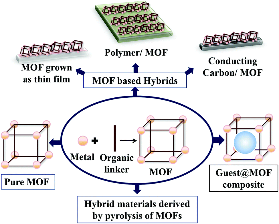
In the last two decades, metal organic frameworks (MOFs) have been extensively investigated to develop heterogeneous electrocatalysts for water oxidation (WO). The scope of reticular synthesis, enormous surface area and accessible internal volume of MOFs make them promising candidates for catalysis. However, low electrical conductivity, slow mass transport and lack of stability restrict the scope of MOF-based WO. In recent times, various material designing approaches, e.g., the introduction of mixed metal and multi-metal systems, ligand engineering, guest@MOF composite formation, preparation of thin films, MOF composite formation with conducting carbon-based materials, metal oxides, polymers and layered compounds, etc. have emerged as an effective means to counteract the aforementioned limitations. This feature article critically discusses the common MOF-based material designing strategies with respect to electrochemical WO and provides a platform to understand the potential of MOFs to prepare a sophisticated hybrid electrocatalyst for WO.
 Subhabrata Mukhopadhyay | Subhabrata Mukhopadhyay, received his MSc degree in Chemistry from the Indian Institute of Technology, Roorkee (India). Later, he joined Prof. Samar K. Das’ research group as a doctoral student, in the year of 2014. His doctoral work comprised synthesis and electrochemical studies of metal–organic framework (MOF) derived materials for application in alternate energy sources. At present, he is working as a postdoctoral fellow with Dr Idan Hod at the Ben-Gurion University of the Negev, Israel. He is currently working on electrochemical CO2 reduction by MOF-based materials. |
 Olivia Basu | Olivia Basu obtained her BSc degree in Chemistry from the Presidency University, Kolkata (India) in 2015. She completed her MSc from the University of Hyderabad (India) in 2017, where she worked on hybrid composites of metalloporphyrins and metal–organic frameworks (MOFs) for application in OER catalysis. She is currently a doctoral student with the research group of Prof. Samar K. Das and her research interest lies in designing functional materials from metal organic frameworks (MOFs) and other supramolecular systems. |
 Rajendar Nasani | Rajendar Nasani received his MSc degree in 2008 from the Osmania University. He pursued his PhD with Prof. Suman Mukhopadhyay (2015), from IIT Indore. His doctoral work was on metal–nitrile/tetrazolate coordination complexes and frameworks. In 2016 he received the National Postdoctoral Fellowship by DST-SERB, and joined Prof. Sanjit Konar's research group at IISER Bhopal India. There, he worked on rare earth metal–organic frameworks and also on radical based magnetic materials. Presently, he is working with Prof. Samar K. Das as a Dr D. S. Kothari postdoctoral fellow. His current research interests include exploration of viologen-POM composites for energy storage applications. |
 Samar K. Das | Samar K. Das obtained his PhD from IIT Kanpur (1995). His first postdoctoral work was on zeolite included compounds with Professor Prabir K. Dutta at the Ohio State University, USA. Later, he worked on giant polyoxometalate clusters with Professor Achim Mueller at Universitaet Bielefeld, Germany. He is currently a Professor at the School of Chemistry, University of Hyderabad (India). He has worked in areas like dithiolene-based materials, polyoxometalates (POMs), MOFs, etc. with the primary objective of developing functional materials of potential applications. Recently, his research group has focused on developing POM- and MOF-based materials for OER and HER catalysis. |
Introduction
For the past few decades, fossil fuels have been our main energy source, and are not only depleting at an alarming rate but have also been of major environmental concern. Besides, looking at rising socioeconomic standards and environmental concerns along with technological advancements, it is evident that with growing energy consumption, the urge for the generation and efficient storage of clean and renewable energy is also growing exponentially.1–3Of the many available means, harnessing solar energy is the most promising option, since it has the capacity to sustain the entire planet. A two-step process, which involves (a) the conversion of solar energy to electrical energy using a photovoltaic cell and (b) storage of the electrical energy in the form of chemical energy of molecules, cumulatively constructs a path to generate fuel using sunlight.3–7 It is the second step of this energy conversion process where electrochemical water splitting (WS) can play the prime role; here, the electrical energy is stored in the chemical bonds of H2. H2 being a clean source of high-density energy, has been considered as a potential replacement of fossil fuels. Hence, drawing inspiration from photosynthesis – the most efficient solar energy harvesting process, scientists have been relentlessly optimizing the electrochemical OER catalysts over the past few decades.6,8–28
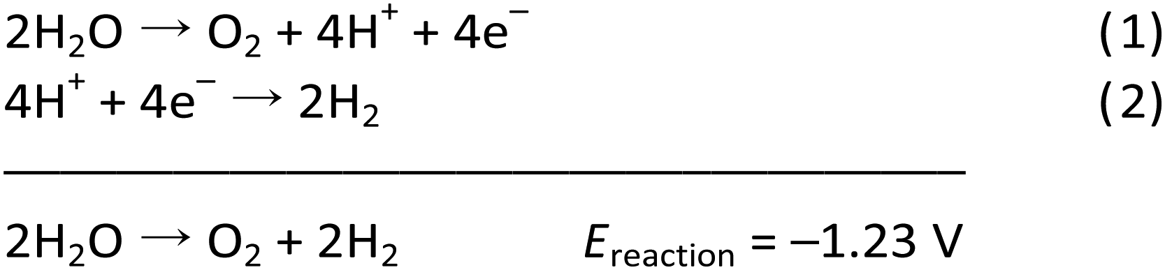
Electrochemical WS comprises two fundamental processes – water oxidation (WO)/oxygen evolution reaction (OER) (an anodic reaction), and hydrogen evolution reaction (HER) (a cathodic reaction), as shown in Scheme 1.
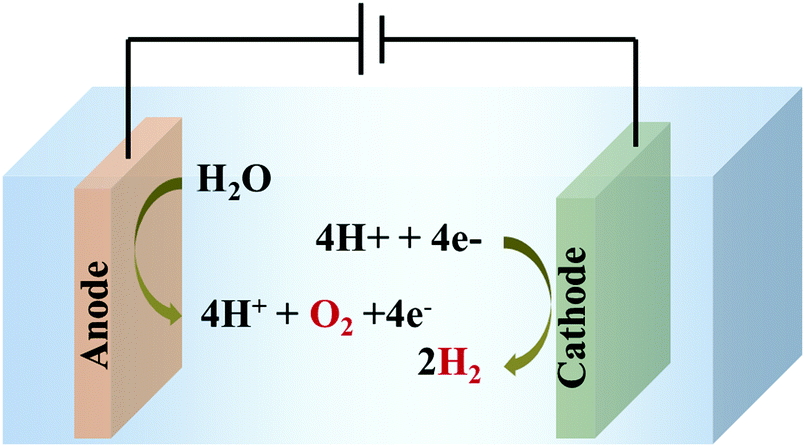 | ||
| Scheme 1 Electrochemical water splitting to generate O2 and H2 by simultaneous water oxidation (at the anode) and water reduction (at the cathode), respectively. | ||
The OER (eqn (1)) is thermodynamically more demanding than the HER (eqn (2)).7,22,29–35 The OER involves ‘O–H’ bond breaking and ‘O–O’ bond making through a series of multistep processes, which again involves several intermediates and an overall transfer of 4e−/4H+. It needs to overcome a high kinetic energy barrier and has a high overpotential requirement.13,27,36–46 Thus, it is crucial to develop a robust and efficient OER catalyst to accomplish overall water splitting in a satisfactory manner. Of note, WO is also important for several crucial processes related to the alternate energy research. For various electrochemical processes, WO acts as the source of protons, which is essential to advance the overall process without the participation of a sacrificial agent. Thus, it is of prime importance to develop efficacious and stable OER catalysts, to make the complete system of solar energy harvesting viable.
Parameters relevant to OER catalysis
The efficiency of an electrochemical catalyst in general is defined in terms of (1) overpotential (η) requirement, (2) obtained current density, (3) faradaic efficiency (FE), (4) turnover number (TON), (5) turnover frequency (TOF) and (6) durability under operational conditions. As has already been mentioned, the multistep OER process has a high overpotential requirement. Therefore, it is always preferred for a catalyst to perform the OER with minimum overpotential. In addition, for real life application, high and stable catalytic current density is crucial. Thus, the overpotential (η) requirement to obtain a current density (j) of 10 mA cm−2, i.e., η10 is considered as an important parameter to define the efficiency of a catalyst.6,7,24 FE is a measure of the conversion of electrical energy into chemical energy during the OER. TON and TOF are two key parameters, of which TON gives an estimate of the amount of product produced (in this case oxygen) per active catalytic site in the complete lifetime of the catalyst and TOF gives the amount of oxygen produced per active catalytic site per unit time. Defining TOF is a more acceptable means of quantifying the efficiency of an OER catalyst while TON relates to the performance of a catalyst with its stability under operational conditions. Stability is another important factor for real-life applicability of a catalyst.47–51 The stability of an OER electrocatalyst can be determined by a combination of controlled experiments and various characterization techniques (electrochemical and spectroscopic). Additionally, it is worth mentioning that determination of the Tafel slope is an important tool to elucidate the mechanism involved.13,16Electrocatalysts for the OER
OER catalysts can be classified as homogenous catalysts (molecular) and heterogeneous catalysts (with extended structure), based on the physical state of the active species. However, during the course of time, this classification appeared to be less appropriate as many homogeneous catalysts were reported not to behave as a molecular catalyst, whereas various heterogeneous catalysts were reported in which the catalytic OER was performed by a molecular functional unit present within the structure.3,5,36 Hence, it is more important to understand if a proposed catalyst is a true catalyst in nature, which can perform WO by itself, or if it gets converted to any secondary extended structure under the operational conditions of WO. If a catalyst can perform WO as a true catalyst, whether in a homogeneous or heterogeneous manner, it would be of more interest than the ones which get converted to a secondary extended structure (mostly oxides) under highly oxidative environment of electrochemical OER.6,7,52,53In this regard, MOFs and MOF-derived materials are being considered to possess enormous potential, since MOFs behave as a heterogeneous assembly of numerous molecular functional units packed in a relatively small volume, and all of these functional units can ideally participate in OER electrocatalysis, similar to independent molecular entities.54–56 The two major structural advantages of MOFs are their extraordinarily high surface area, and permanent porosity. This allows the reactants (in this case, water molecules) and products (in this case, oxygen) to easily diffuse to and from the catalytic sites in the MOF. Additionally, by careful choice of the metal ion and organic linker, it is possible to fine-tune the size and nature of the pores and channels existing inside MOFs. Now, since most of the MOFs have a highly crystalline structure with self-repeating units, it provides a scope for understanding the structure–function relationship of MOF-based materials. However, it should also be mentioned that many of the pristine MOFs suffer from the shortcoming of significantly low electrical conductivity and in a few cases, lack of hydrophilicity inside the pores. Therefore, designing an efficient OER catalyst out of MOFs would require a careful consideration of a few points – (1) the transport of both charge and mass through the framework should be well balanced; (2) the transport of reactants/products and charge should take place faster than the rate of catalysis – so that the catalyst can perform to its optimum level and its efficiency is not limited by mass transport or charge conduction. Over the past few years, several studies on the mechanistic details of the charge transfer phenomenon in MOFs have been carried out, which can help as a guide to design better electrocatalysts.45,57–59
Various catalysts have been developed for the OER in the last few decades.26,37,48,60–64 In a parallel growing field, enormous progress has been made in the area of MOFs and MOF derived materials.19,23,36,47,62–67 But, the connection between the field of designing a WO catalyst and a MOF was occasional in the initial stages.24,47,56,68,69 In recent years, a few review articles in the field of heterogeneous water splitting,7,70 electrochemical applications of MOFs,51,64,71–74 electrochemical OER of MOFs,25,75etc. have portrayed the scope of the MOF-based OER. However, the evolution of MOF-based material designing strategies to prepare an OER catalyst, within the period of the last five years is highly interesting and requires periodical reviewing. This feature article mainly focuses on this constant development of material designing strategies to prepare MOF-based electrocatalysts for the OER. For the sake of clarity, the discussion will be divided under four different major headings: (1) pristine MOFs and its structural engineering for OER catalysis; (2) guest@MOF composites for electrochemical OER; (3) MOF derived hybrid materials (such as, MOF supported systems, thin films, etc.) and (4) hybrid materials derived by pyrolysis of MOFs. The several types of OER electrocatalysts prepared using a MOF are schematically represented in Scheme 2.
 | ||
| Scheme 2 Design strategy of MOF-based water oxidation (WO) catalysts by using pure MOF, guest@MOF, MOF-based hybrid materials and materials derived by pyrolysis of MOFs. | ||
1. Pristine MOFs and its structural engineering for OER catalysis
MOFs, which are a combination of metal nodes and connecting organic linkers (any bi- or polydentate organic ligand), leave us with a plethora of opportunities to explore. Furthermore, being highly porous and crystalline materials, they offer well-arranged and easily accessible catalytic sites, which makes it comparatively easy to assess the reaction mechanism. With growing interest in the field of designing and fabricating MOF-based electrocatalysts, Wang et al. prepared a cobalt containing zeolitic imidazolate framework (CoZIF-9) {[Co(bim)2]} with a benzimidazolate (bim) linker.46 A careful structural analysis revealed that the fabricated electrocatalyst comprised of imidazolate bridged CoII ions tetrahedrally connected to each other. Interestingly, the choice of benzimidazole over imidazole during the fabrication of the MOF was found to be not only crucial in increasing the stability of the MOF under high electrochemical OER anodic potential but also having an influence on the catalytic property of the MOF as was supported by DFT calculations and molecular simulations. On the other hand, in the majority of cases, the coordination environment around the catalytic centre was found to affect its electrocatalytic activity. One such study was conducted by Lu et al. on Co-benzotriazole MOF systems: MAF-X27-Cl and MAF-X27-OH.76 It can be seen from the respective molecular formulas – [Co2(μ-Cl)2(btta)] for MAF-X27-Cl and [Co2(μ-OH)2(btta)] for MAF-X27-OH (H2bbta = 1H,5H-benzo(1,2-d:4,5-d′)bistriazole), that the only difference between these two sister MOFs lies in the coordination sphere of the active cobalt catalytic centre. From the experimental outcome, it was shown that the presence of μ-OH ligand made MAF-X27-OH a superior OER catalyst than MAF-X27-Cl.It is well known that different metal ions with their specific electronic structures and redox properties may exhibit electrocatalytic activity with different magnitude. In other words, for a given linker combination in a MOF, a change in the metal node may lead to a change in the catalytic activity as explained by Gong et al.77 in one of their reports. They fabricated three MOFs from three different metal nodes, i.e., Co, Cu and Zn, and a common polydentate organic linker L ([4-(5-(pyridin-4-yl)-4H-1,2,4-triazol-3-yl) benzoic acid]) and commonly formulated as M2L4·3H2O, with a common topology 44-sql. Later, on careful electrocatalytic analysis, it was revealed that a MOF with a cobalt node showed better activity compared to that of the copper MOF; the zinc containing MOF stood inactive. Though a detailed mechanism was not provided, the results were attributed to difference in coordinative unsaturation around the metal centre which is mostly being controlled by the electronic structure of the metal centre. This clearly points out that a change in the node leads to a change in activity. Inspired from such a metal node dependent activity study, interest in designing and fabricating MOFs with complex node systems, like polynuclear (homo- and/or hetero-nuclear) nodes and mixed metal nodes, has increased. A few of those studies have been presented in later sections.
1a. MOFs with polynuclear (metal cluster) nodes
Inspired by different inorganic OER catalysts having multi-metallic nodes, Gutiérrez-Tarriño et al. prepared a MOF formulated as {[Co2(BTC)1,3(DMF)2]-[Co2(BTC)1,3(DMF)2py]} (Co2-MOF) which constituted of two dissimilar binuclear secondary building units (SBUs); out of which, one of the SBUs was made up of two crystallographically independent cobalt centers.78 Unfortunately, chemical stability studies revealed that the Co2-MOF was unstable in the presence of protic solvents like ethanol, water and their mixture, and was readily being hydrolysed to a different mononuclear cobalt-MOF. But it could be evaded by dispersing Co2-MOF in an alcoholic solution of Nafion. Interestingly, Nafion in the system not only enhanced protic solvent stability of the Co2-MOF catalyst but also assisted in improving its adherence to graphitic electrodes. Besides, electrocatalytic studies divulged that, Co2-MOF displayed superior water oxidation TOF values compared to that of a similar mononuclear Co-MOF, showing the advantage of fabricating polynuclear MOFs. Similarly, there is a recent report from Ibrahim et al., presenting a Co-trinuclear metal node containing MOF {[Co3(pyz)(fa)3(dmso)2]2H2O}n, (pyz = pyrazine, fa = fumarate, dmso = dimethyl sulfoxide), that demonstrates notable performance towards the electrochemical OER in neutral pH.79 Inspired from the multi-metal functional unit of plant photosystem, PS-II, Jiang et al. prepared a tetranuclear cobalt cluster (Co4O4 cubane in the core) containing Co-citrate open framework (UTSA-16).80 This was the first report of a MOF-based OER catalyst, designed with a tetra-cobalt cubane type core. Owing to the synergistic cooperation of the {Co4O4} cubane core with in situ formed high-valent cobalt centers and an open framework structure, UTSA-16 showed excellent OER activity, comparable with that of RuO2 and even surpassed its standard Co3O4 counterpart.Apart from cobalt, researchers have also explored other transition metals in their quest to develop MOFs with polynuclear metal nodes. Recently, Wang et al. have developed a new alkaline stable MOF [Ni4(OH)2(NDC)3(H2O)2]·2H2O (Ni-MOF), with a tetranuclear Ni4 (μ3-OH)2 cluster as a metal node.81 This Ni-MOF performed quite well as an electrochemical catalyst for the OER. But, from several post-OER characterizations, it was found that this Ni-MOF underwent a phase transformation to form β-Ni(OH)2, such that both Ni-MOF and β-Ni(OH)2 coexisted in the same material. This new composite, formed by the partial leaching of the ligand, proved to be a better electrocatalyst for the OER as compared to β-Ni(OH)2 and Ni-MOF separately (Scheme 3). According to the authors, such a catalytic outcome might be a result of some synergistic interaction between the two catalytically active species β-Ni(OH)2 and Ni4 (μ3-OH)2. Additionally, the leaching of the ligand from the MOF created several void spaces, thereby increasing the specific surface area of the material. This facilitated the electrolyte and ion movement and exposed more active sites on the surface. In addition to this, the formation of β-Ni(OH)2 also improved the electrical conductivity of the material. Moving a step forward, in a different approach, Dong et al. employed a mixed-metal cluster strategy for synthesizing MOFs.82 In the first step, two heteronuclear MOFs were prepared PCN-250-Fe2M (M: Co or Ni) [heteronuclear cluster Fe2M = Fe2M(μ3-O) (CH3COO)6(H2O)3]. And in the second step, a new MOF PCN–Fe2Co–Fe2Ni was prepared by mixing both the heteronuclear clusters Fe2Co and Fe2N (Fig. 1); a comparative study of electrocatalytic activity of these three materials was then conducted.
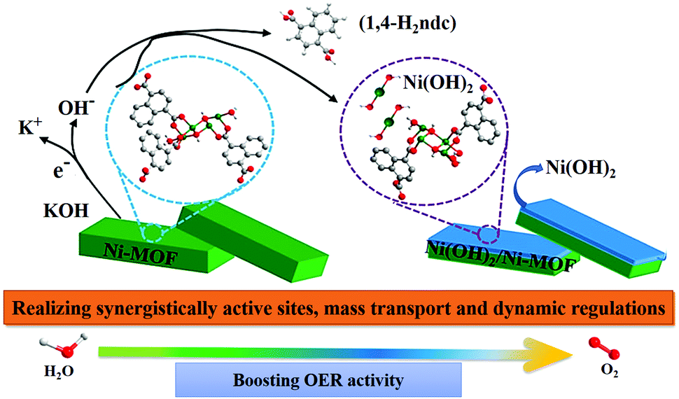 | ||
| Scheme 3 A schematic representation of the transformation of Ni-MOF to Ni(OH)2/Ni-MOF heterostructure and the synergistic catalytic OER process by Ni(OH)2/Ni-MOF. Adapted with permission from (ref. 81). Copyright (2020) American Chemical Society. | ||
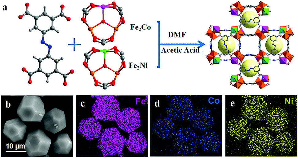 | ||
| Fig. 1 (a) Schematic diagram of the synthesis of PCN–Fe2Co–Fe2Ni. (b) Scanning electron microscopy (SEM) image and (c–e) corresponding elemental (Fe, Co and Ni) mapping images for PCN–Fe2Co–Fe2Ni. Adapted with permission from (ref. 82). Copyright (2019) American Chemical Society. | ||
1b. MOFs with mixed-nodes
It has been found in several studies that the presence of different kinds of metals in a MOF tends to improve the electrocatalytic activity of the MOF towards the OER. A synergistic coupling between the metal centers has been suggested to be a driving force for such behaviour.From a library of strategies, employing a metalloligand (e.g., metalloporphyrin) can be a very useful technique to incorporate active catalytic sites and thus to generate multi-metallic MOFs. In the year 2016, Usov et al. reported a Ni-porphyrin based MOF (PCN-224 (Ni)), where the metal nodes were made of a Zr-oxo cluster while Ni-tetracarboxyphenylporphyrin (Ni-TCPP) acted as the metalloligand connecting the nodes.83 Even though it was proved that the Ni-porphyrin functioned as the active catalytic center, the Zr-oxo metal nodes played an important role in the overall catalytic activity of PCN-224 (Ni), by increasing the hydrophilicity of the MOF. Another advantage of such systems is that the chances of degradation of the MOF by oxidative cleavage of the bond between the metal nodes and organic linker (in this case, metalloligand) is very low, since the metal ion of the metalloligand itself (and not the metal node) is supposed to be the catalytic site. Apart from in situ synthesis, post-synthetic modification (PSM) can also be a promising strategy for incorporating functionality into a MOF matrix. In a work by Maity et al., doping of CoII ions into a Cd-MOF crystal was performed simply by dipping the MOF in a Co(NO3)2 solution (in DMF).84 The final material thus formed by virtue of chemical bond formation between the CoII ions and the previously uncoordinated pyridine ligands of the Cd-MOF, was rendered active towards OER electrocatalysis. In order to study the effect of incorporating mixed-nodes in the same MOF structure, towards OER electrocatalysis, Gao et al. selected the Hofmann family of MOFs.85 Hofmann MOFs can be designated by the formula [M]L[M′(CN)4] (M for Fe2+, Co2+, Ni2+, Zn2+; L for pyridyl or dipyridyl derivatives; M′ for Ni2+, Pd2+, and Pt2+). As is evident from the formula, this MOF provides a wide scope of chemical tunability with all the possible combinations of metal ions and ligands. The authors utilized this feature to develop a series of Hofmann MOFs and studied their catalytic activity towards the OER. In the same year, another group of researchers reported a series of mixed-node MOFs with the formula CoxFe1−x-MOF-74 (0 < x ≤ 1). They were also successful in unveiling some of the mechanistic details of OER catalytic activity in such mixed-node MOFs.86 According to their findings, the electron density on the cobalt nodes was larger in Co0.6Fe0.4-MOF-74 (MOF in the CoxFe1−x-MOF-74 series having a better activity than Co-MOF-74) than its mono-metallic analogue, Co-MOF-74. Such a phenomenon was suggested to be a result of Fe-doping in the MOF, causing a shift in electron density from Fe to Co. This also explains the improved performance of the catalyst, since a higher electron density over the active catalytic center would facilitate the formation of hydroperoxy (OOH) species, which is a crucial intermediate in the water oxidation process.87,88 A similar MOF-74 based electrocatalyst had also been prepared by Zheng et al., using Fe–Ni metal nodes.89 Interestingly, they discovered that the initial source of iron metal used for doping the Ni-MOF seemed to affect the catalytic performance of the MOF catalyst.90 A similar conclusion was also reached by Zhang et al. in their recent work, where they reported a series of Fe doped Ni-MOFs employing different Fe ion sources. In another work by Wan et al., morphology-dependent catalytic activity of a MOF was observed, where a 3D-flower like structure was formed out of MOF nanosheeets.91
The use of two-dimensional (2D) MOFs as catalysts has an added advantage of more exposed active sites and better ion or mass transport across the layers. Owing to these benefits, the use of MOF nanosheets as an OER catalyst is slowly gaining popularity among researchers. In a recent work, Li et al. prepared nanosheets of a two-dimensional (2D)-MOF (CoxFe-MOF), isostructural to Co2(OH)2BDC MOF.92 The optimized catalyst Co3Fe-MOF had better efficiency than its single-metal counterparts, Co-MOF and Fe-MOF. And the prime reason behind such an effect was the higher electrochemically active surface area (ECSA) of the mixed-node MOF than the rest. Another 2D CoFe-MOF was reported by Xu et al. as an electrocatalyst for the OER.93 But what was more important in this work was the synthetic strategy behind the formation of highly crystalline MOF nanosheets with a network of micro- and mesopores. Its synthetic procedure comprised of a two-step – ultrasound-assisted synthesis of MOF nanosheets, followed by solvothermal treatment (Fig. 2). The material thus formed had hierarchical porosity with a higher number of exposed metal sites, which is one of the most desirable properties of any MOF-based OER catalyst. Apart from using different combinations of just two metal ions, researchers have even gone for preparing trimetallic MOFs for catalysing the OER. In one such work, Bai et al. prepared a hierarchical coordination polymer film employing Co, Ni, and Fe metal sources.94 The novelty of the work lies in the synthetic procedure, where they had used a spray-assisted miscible liquid–liquid interface (MLLI) strategy, which led to the formation of films having a 3D hierarchical network structure.95 Another such work focusing on the preparation of trimetallic-MOFs having a hierarchical foam-like architecture, was reported by Qian et al. In this work, the authors presented a mild one-pot room temperature synthesis for the large-scale synthesis of the NiCoFe-based MOF nanofoam (denoted as (Ni2Co1)1−xFex-MOF-NF).
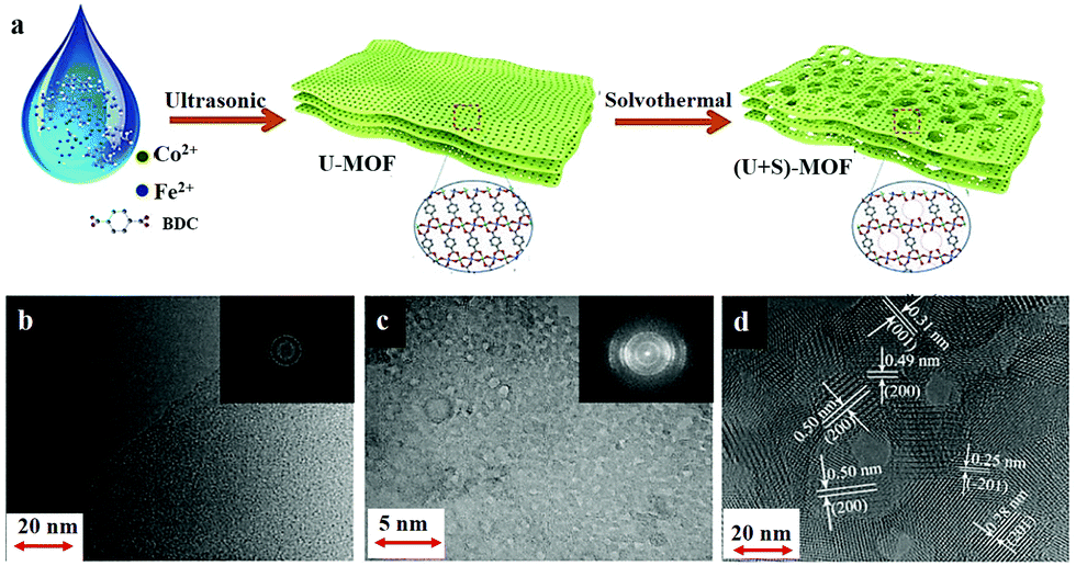 | ||
| Fig. 2 (a) Schematic illustration of the two-step synthesis of hierarchical 2D CoFe-MOFs, involving ultrasound-assisted (U) synthesis (Step I) followed by the solvothermal (S) treatment (Step II). It also shows the structural evolution of the MOF nanosheets in the process. Comparison of TEM images of the CoFe-MOFs prepared by (b) only ultrasonic synthesis and (c) the two-step synthesis, with the inset of the SEAD patterns, respectively. (d) HRTEM image of (U + S)-CoFe-MOF, showing the crystalline structure and hierarchical pores. Adapted with permission from (ref. 93). Copyright (2019) American Chemical Society. | ||
MOFs with mixed-nodes are in general found to perform better than their single-metal counterparts, as an OER electrocatalyst, owing to the enhanced charge-transfer kinetics and their increased electrochemically active surface area (ECSA). Table 1 compares the OER activities of metal node engineered MOFs.
| Catalyst | Overpotential ηx (mV) x = current density (mA cm−2) | pH | Ref. |
|---|---|---|---|
| Co2-MOF@Nafion | η 2 = 460, η5 = 537 | 7 | 78 |
| Compound 1 | η 1 = 257 | 7 | 79 |
| CoCd–BNN | η 1 = 353 | 13 | 84 |
| CoFe–PYZ | η 10 = 300 | 13 | 85 |
| NiCo–PYZ | η 10 = 362 | 13 | 85 |
| NiFe–PYZ | η 10 = 560 | 13 | 85 |
| Co0.6Fe0.4-MOF-74 | η 10 = 280 | 14 | 86 |
| Co3Fe–MOF | η 10 = 280 | 14 | 92 |
| CoFe–MOF | η 10 = 277 | 14 | 93 |
| FeNi-DOBDC-3 | η 50 = 270, η100 = 287 | 14 | 84 |
| UTSA-16 | η 10 = 408 | 14 | 80 |
| Fe0.38Ni0.62-MOF | η 10 = 190 | 14 | 91 |
| (Ni2Co1)0.925Fe0.075-MOF-NF | η 10 = 257 | 14 | 95 |
| PCN–Fe2Co–Fe2Ni | η 10 = 271 | 14 | 82 |
1c. Linker engineered MOFs for OER catalysis
Even though there are a lot of studies on the effect of incorporation of different metal ions in a MOF on its OER catalytic activity, much less has been explored on the effect of ligand modification. The early examples of ligand modification can be found in the works of Gong et al., where they prepared MOFs with the same metal ion and linker ligands, but different coligands.96,97 And interestingly, certain differences in the electrochemical activity of the sister MOFs were observed, due to the differences in their co-ligands and electrochemical environment.In another work, Johnson et al. by means of a post-synthetic ligand exchange method incorporated a molecular OER catalyst [Ru(tpy)(dcbpy)(OH2)](ClO4)2 (tpy = 2,2′:6′,2′′-terpyridine, dcbpy = 2,2′-bipyridine-5,5′-dicarboxylic acid) into a FTO-grown thin film of UiO-67 MOF, to give a MOF-based OER catalyst, UiO67-[RuOH2]@FTO.44 Later, the same group designed another OER catalyst by means of post-synthetic ligand modification from MIL-101Cr MOF.98 In this case, a Ru(bda) (bda = 2,2′-bipyridine-6,6′-dicarboxylate)-based molecular OER catalyst was very strategically placed into the pores of the MOF by means of anchoring it with the linker ligand of the concerned MOF. The catalyst thus formed in both cases, turned out to be a better OER catalyst than their respective Ru-based molecular catalyst complex. It is believed that the immobilization of the molecular catalyst and modified micro-environment around it, inside the MOF cavity, provided enough stability to it to perform as a better catalyst.
Xue et al. explored the possibility of combining both the strategies of using mixed-metal nodes as well as using mixed ligands to prepare a MOF-based OER catalyst.99 This heterogeneous MOF, defined as A2.7B-MOF-FeCo1.6, was prepared by using two different linker ligands – terephthalic acid (A) and 2-aminoterephthalic acid (B). In the following year, 2019, another mixed ligand MOF was reported by Han et al., prepared by employing mixed organic ligands including rigid 1,5-bi(imidazolyl)anthracene and dibenzobarrelene skeletons based dicarboxylic acid.100
In another piece of work, a group of researchers studied the role of different anionic ligands in a bimetallic MOF derived OER catalyst, in tuning the electronic environment around the active catalytic center.101 Ligand modification has also been reported to influence the transformation of MOFs to Co(O)OH phase during an electrocatalytic process.102 And a systematic study of the same can help us to understand and control this transformation process in order to prepare better OER catalysts.
2. Guests in MOFs for electrocatalytic OER
An important feature of the MOF architecture is its pores and exceptionally high porous volume. If the pores or cages of MOFs can be functionalized by confining any catalytically active species inside it such that it will not be able to leach out of the pore/cage due to geometrical constraints, or due to interaction with the internal surface of the MOF, it can be termed as ‘activation by means of encapsulation’ (Scheme 4).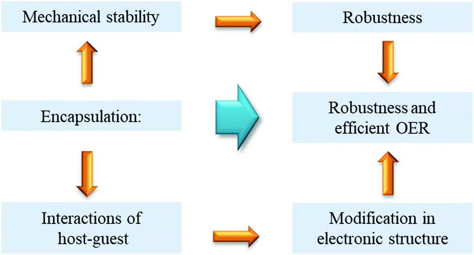 | ||
| Scheme 4 Benefits of guest encapsulation in MOFs for OER catalyst designing. | ||
Although this fundamental approach of preparing heterogeneous functional materials is well-studied for various porous materials, e.g., zeolites, it is not yet fully explored to design MOF-based OER catalysts. Reports of organic substrate oxidation based on Metal@MOF103,104 and Molecule@MOF105 are more frequent than similar OER catalysts. For designing a guest@MOF OER catalyst, the choice of the MOF and the guest species is crucial and depends on several factors. One of the most important factors is the size consideration, i.e., the size of the guest should be small enough so that it fits well inside the cavity of the MOF but it should be big enough not to leach out of the windows of the cavity. The host MOF in this case might actively participate in the catalysis, or may just act as a storehouse for the catalyst. But whichever the case may be, it has been found in several reports that the MOF framework plays some role in modifying the electronic structure of the guest molecule and thus, may also influence its catalytic activity. Guo et al. reported excellent OER activity by Pt-loaded Co and Ni-Prussian Blue analogous (PBA) MOFs.106 Here, the MOFs had an intrinsic OER catalytic property, which was considerably benefitted by the loading of Pt nanoparticles. For both PBAs, the oxidation state of Co/Ni was slightly increased due to the incorporation of Pt, which acted as an electronegative metal source and stabilized the active metal center in its partially increased oxidation state. With the loading of Pt nanoparticles, the overpotential requirement came down for Co/Ni-PBA and was reported to be comparable with the benchmark electrocatalyst RuO2. The Pt nanoparticle loading resulted in (a) lowering of charge transfer resistance, (b) increase in the number of active sites and (c) stability of Co/Ni in a higher oxidation state; all of which contributed to the better performance of the modified MOF-based catalysts (Co–Pt–PB and Ni–Pt–PB). In a different approach, Nepal and Das encapsulated a high-valent dimeric Mn complex, MnTD ([(terpy)Mn(μ-O)2Mn][(terpy)]3+; terpy: 2,2′:6,2′′-terpyridine) inside the cavities of MIL-101(Cr).107 The composite thus formed was named as MnTD⊂MIL-101(Cr). The Mn(μ-O)2Mn complex as such is active towards OER catalysis but is not stable under the high oxidizing potential of the process. It undergoes oxidative polymerization through an intermolecular reaction pathway and hence loses its activity. By means of encapsulation of the molecule inside the single cages of the MOF, a physical separation was introduced between each unit of Mn(μ-O)2Mn; which prevented its oxidative dimerization. The host–guest composite material was then found to be a promising photocatalyst for the OER.
A similar “ship-in-a-bottle” approach was also explored by our group to prepare a MOF-based OER electrocatalyst. Manna et al. by means of solvothermal synthesis trapped a Co-complex [Co(H2O)4(DMF)2]2 inside the cavity of a flexible ligand containing Co-MOF, Co-WOC-1 [{Co3(μ3-OH)(BTB)2(dpe)2}{Co(H2O)4(DMF)2}0.5]n·nH2O (H3BTB = 1,3,5-benzenetribenzoic acid; dpe = 1,2-di(4-pyridyl)ethylene).108 As a result of confinement, the active unit [Co(H2O)4(DMF)2]2 could not leach out of the MOF during the electrochemical operational conditions (Fig. 3a). The observed TOF was 0.05 s−1, while η1 was 390 mV. The importance of this heterogenous catalyst lies in the enhancement of stability of the trapped [Co(H2O)4(DMF)2]2 unit inside the MOF cavity. The lack of scope of structural rearrangement of the Co-complex to develop an extended structure while being inside the MOF crystal, seems to play a crucial role behind the high stability of the host–guest electrocatalyst.103
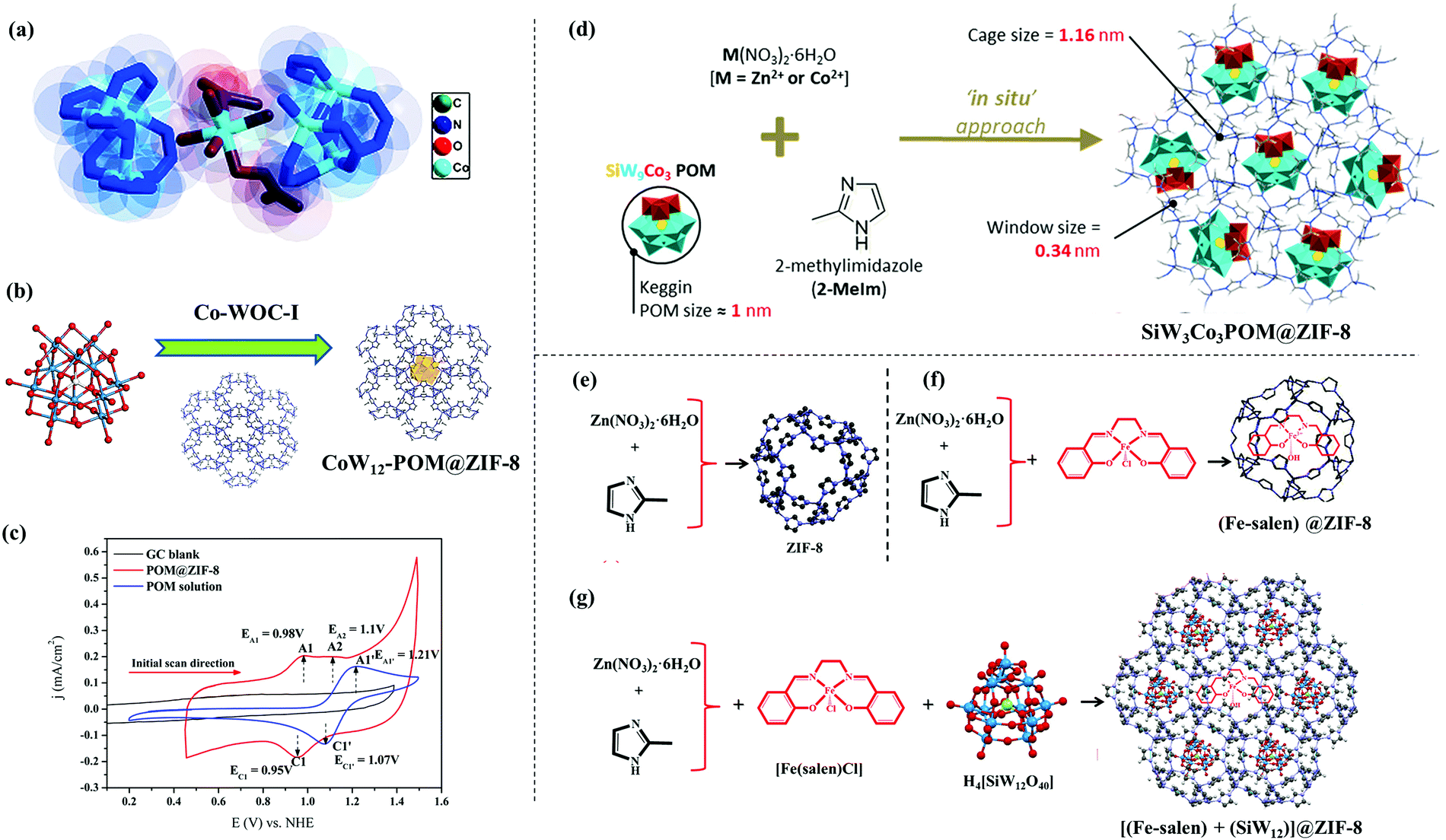 | ||
| Fig. 3 (a) Active site structure of Co-WOC-1. Adapted with permission from (ref. 108). Copyright (2016) John Wiley & Sons. (b) In situ encapsulation of [CoW12O40]6− Keggin inside the ZIF-8 cavity; (c) cyclic voltammograms of POM@ZIF-8 and K6[CoW12O40] recorded in pH 2 0.1 M KCl; reprinted with permission from (ref. 109). Copyright (2018) John Wiley & Sons. (d) Synthetic protocol of SiW9Co3POM@ZIF-8, reprinted with permission from (ref. 110). Copyright (2020) American Chemical Society. (e), (f), (g) Synthetic protocol of ZIF-8, Fe(salen)@ZIF-8 and [(Fe-salen) + (SiW12)]@ZIF-8, respectively. Adapted with permission from (ref. 111). Copyright (2020) American Chemical Society. | ||
In another work from our group, a host–guest composite (POM@ZIF-8) was prepared by means of in situ encapsulation of an unsubstituted Keggin polyoxometalate (POM), i.e., K6[CoW12O40] (guest) inside ZIF-8 (host) (Fig. 3b).109 Due to structural constraints of Keggin POM, it was not expected to act as an OER catalyst, and this is what was found from the electrochemical analysis as well (Fig. 3c), which suggests a complete breakdown of its structure. However, the POM@ZIF-8 composite could perform electrocatalytic OER for a prolonged time. This encapsulation strategy triggered the activation (as probed by XPS analysis) and stabilization (proved by long term electrochemical experiments, XRD, ICP, FESEM analysis, etc.) of the POM towards OER catalysis. A shift in electron density from the electron rich internal surface of ZIF-8 to the low lying ‘W’ centred LUMOs of the POM were found to be crucial. POM@ZIF-8 could perform electrocatalytic OER with high efficiency (TOF = 10.8 s−1) and high stability in neutral pH, having a satisfactory faradaic efficiency (≥95%). This is one of the highest TOFs reported for any heterogeneous electrocatalyst performing the OER in neutral pH. The inherent resistive nature of ZIF-8 was responsible for the high overpotential requirement (η1 = 780 mV).
A similar in situ encapsulation of a catalytically active Keggin POM inside the cavity of ZIF-8 and ZIF-67 was explored by Abdelkader-Fernández et al. to study the effect of the encapsulation on their OER catalysis (Fig. 3d).110 It was found that the OER activity of the host–guest composite POM@ZIF-67 was better than the POM or ZIF-67 as such; while no notable enhancement was observed in the case of the POM@ZIF-8. A comparison of these systems helped the authors to understand the two ways in which the encapsulation helped the OER catalysis of the composite, i.e., (a) synergistic interaction between the POM and the MOF inner surface and (b) an increase in defects in the MOF as a result of the encapsulation.105
Recently, another OER catalyst based on a host–guest system was prepared by us using ZIF-8 as a host and [Fe(salen)]Cl as the guest species (Fig. 3e and f).111 The guest as such is unstable towards electrochemical OER but was found to function as a stable OER catalyst after encapsulation. This was the first report of catalytic OER activity by Fe-salen. Furthermore, a Keggin POM [SiW12O40]4− was co-encapsulated in the cages and also was grown on the surface of ZIF-8 nanocrystals with an aim to increase the charge transfer efficiency. This strategy was reported to perform electrocatalytic OER with a high TOF of ∼5 s−1 and comparatively low overpotential requirements. A similar approach was also found to be helpful to prepare another electrocatalyst for the OER using a porphyrin molecule, i.e., Co-tetramethoxy phenylporphyrin (CoTMPP) as a guest and ZIF-8 as a host material. The catalyst thus prepared, i.e., CTMZ-8 was found to be an active OER catalyst in a wide pH window ranging from neutral to acidic. The above-mentioned catalyst was reported to perform the OER with a TOF of ∼2.7 s−1 and an overpotential requirement of 387.4 mV to achieve a current density of 1 mA cm−2.112 All these examples show that guest@MOF can be a very promising approach to design a MOF based electrocatalyst for the OER, because it can act as a bicomponent system in synergistic interaction with each other, where each component has its own role in the overall catalysis process. The design strategy of guest@MOF composites involves plenty of scope of in situ and ex situ modifications, which may lead to unprecedented catalytic activity and stability.
3. MOF-based hybrid composites
From earlier sections, it is evident that there are a wide variety of MOFs for electrocatalytic water oxidation reactions. But, because of their poor conductivity and comparatively low stability limits, their applicability for OER catalysis under harsh experimental conditions like varying pH and high applied voltages is limited. To circumvent these disadvantages, many research groups have been working on designing and fabricating hybrid electrocatalysts by combining MOFs with other conducting materials, e.g., conducting organic polymers, graphene, carbon nanotubes (CNTs), MXene type metal carbides/nitrides, metal and metal oxides, etc.3a. Organic polymers/MOF hybrids
There are a few examples related to preparation of hybrids with organic polymers and MOFs, e.g., PANI/MOF, PABA/MOF etc. (PANI = polyaniline; PABA = poly(3-aminobenzoic acid)) for applications in diverse fields including catalysis.113–116 In most of these cases, the polymer played an important role to enhance the electronic conductivity of the composite. Though there are many such examples of polymer/MOF hybrids, systems dealing with electrocatalytic OER are not very common. Dang et al. reported an organic polymer supported MOF, which had been employed for electrocatalytic OER reactions.117 A bi-metallic (CoNi-NDC) MOF was solvothermally grown on to a polyaniline (PANI) layer deposited onto a nickel foam (NF) current collector to yield CoNi-NDC/PANI-NF electrode. The hybrid electrode could behave as a durable electrocatalyst for the OER with low overpotential (η10 = 353 mV) requirement and also followed a fast kinetics (Tafel slope = 73.3 mV decade−1). The higher activity was attributed to the presence of conductive polymer, which helped in effective charge transfer from MOF to NF. This example certainly proves that there is a lot of scope in exploring conductive organic polymer/MOF hybrid based OER electrocatalysts.3b. Conducting carbon material/MOF hybrids
Owing to their high surface area and oxygen rich surfaces, conducting carbon-based materials like graphene oxide (GO) and CNTs are anticipated to be ideal candidates to accompany MOFs resulting in hybrid composites. As improving charge transfer ability of the MOF composite would increase the catalytic activity, Sohrabi et al.118 fabricated a 3D network of PCN-224/multiwalled carbon nanotube (PCN-224/MWCNT, PCN = porous coordination network) comprising 3D nanochannels. It was presumed that MWCNTs would contribute towards enhancing the conductivity. Whereas, the rationale behind selection of PCN-224 was the presence of robust Zr6 nodes. On the other hand, a metalloporphyrin, tetrakis(4-carboxyphenyl)porphyrin-CoII (CoTCPP) linker with a coordinatively unsaturated and catalytically active cobalt center would make the composite a good candidate towards the OER.Besides CNT/MOF composites, there are ample reports on graphene/MOF hybrids, where graphene not only acts as a conducting support to grow the MOF but also prevents aggregation. A report from Xie et al.119 illustrated excellent catalytic OER by 10 mg 3D graphene (Gr) loaded Gr/Ni-MOF composite. The enhanced activity was attributed to fully exposed, ultrasonically dispersed, and strongly bound Ni-MOF along with synergistic interaction between the MOF and graphene.
In addition, there are some interesting examples, where these 1D and 2D carbons act as struts and penetrate the MOF crystal lattices. Oxy groups of the carbon material directly take part in the formation of the metal coordination sphere and strengthen the composite structure. Apparently, this strut property of carbons not only stabilizes the composite even in the most harsh reaction conditions, taking advantage of effective communication between active metal centers and conducting medium, but also enhances catalytic activity. Jahan et al.120 solvothermally fabricated a potent tri-functional (effective catalyst for HER, OER and ORR) electroctalyst, graphene-oxide (GO)/MOF composite. Later on, a strong, durable, and highly active Co-MOF@CNTs bifunctional catalyst was grown following a self-assembly strategy by Fang et al.,121 where the CNTs acted as struts and were inserted into the MOF crystals. The augmented activity of the composite was ascribed to the synergistic interaction between the metal, ligand, and CNT struts.
3c. MXene/MOF hybrids
MXenes are a class of transition metal carbides, nitrides and carbonitrides and are relatively young members in the 2D conductive layered materials. These are generally few-atom-thick 2D layers, and due to their flexible nature, excellent conductivity and ease of processability, these materials have soon been found to be useful in various applications. They are generally formulated as Mn+1XnTx (M = transition metal, X = C and/or N, Tx = surface functional groups like –O, –OH, and/or –F, etc.) and because of their unique atomic arrangements, they are intrinsically conductive in nature and are among the best candidates in providing conductive supports/surfaces to fabricate organic–inorganic composites. There are a few instances, where MXenes were found to act as a conductive support for MOF-based OER catalysts, where a synergistic interaction between the two enhanced the catalytic performance of the composite. Zhao et al.122 fabricated a CoBDC/Ti3C2Tx (BDC = 1,4-benzene dicarboxylate) hybrid material, adapting an interdiffusion reaction-assisted process, where CoBDC was grown on 2D nanosheets of MXene. As a result of their synergistic interactions between the MOF and the Ti3C2Tx, the hybrid could behave as a good electrocatalyst for the OER with low overpotential (η10 = 410 mV) requirement and also followed a fast kinetics (Tafel slope = 48.2 mV decade−1). Similarly, a bimetallic MOF (CoNi-ZIF-67) and MXene based hybrid electrocatalytic OER catalyst (CoNi-ZIF-67@Ti3C2Tx) was reported by Wen et al.,123 adopting a coprecipitation technique. Systematic electrocatalysis examinations revealed that, the generated hybrid exhibits better catalytic activity than the standard IrO2 and the MOF itself. The enhancement in electrocatalytic activity was attributed to the three-fold benefits, that is (a) synergistic effects resulting into enhanced conductivity, (b) increased oxidation states of Co and Ni on the introduction of MXene to MOF, and (c) smaller MOF particle size along with enhanced electrochemically active surface area (EASA), etc.3d. Metal chalcogen/MOF hybrids
Generally metal oxide nanoparticles (MNPs) are catalytically active towards electrocatalytic OER.124,125 But, owing to their small size, large surface area and surface energy they are prone to form aggregates and reduce their efficiency on their application for a prolonged period.48 In this context, MOFs not only provide them support but also, in suitable conditions, they can form core (MNP)–shell (MOF) type composites. Additionally, the resultant composite, being a multimetallic system with incoming metal entities, act synergistically and enhance the overall catalytic efficiency.Evidently in one of their reports, Wang et al.126 have fabricated a Ni-BDC-MOF shell protected Ni3S2/NiS hollow nanoparticle (NP) based catalytic system for OER applications. The MOF was grown on the preformed MNPs solvothermally (Scheme 5). The composite showed improved activity compared to that of its individual components and even outperformed the Ru2O reference. The hydrophilicity and coordinative unsaturation of the Ni-BDC shell and highly porous and conducting Ni3S2/NiS core with strongly coupled interface contributed in enhancing the catalytic activity along with observed prolonged durability (notable activity for 15 h).
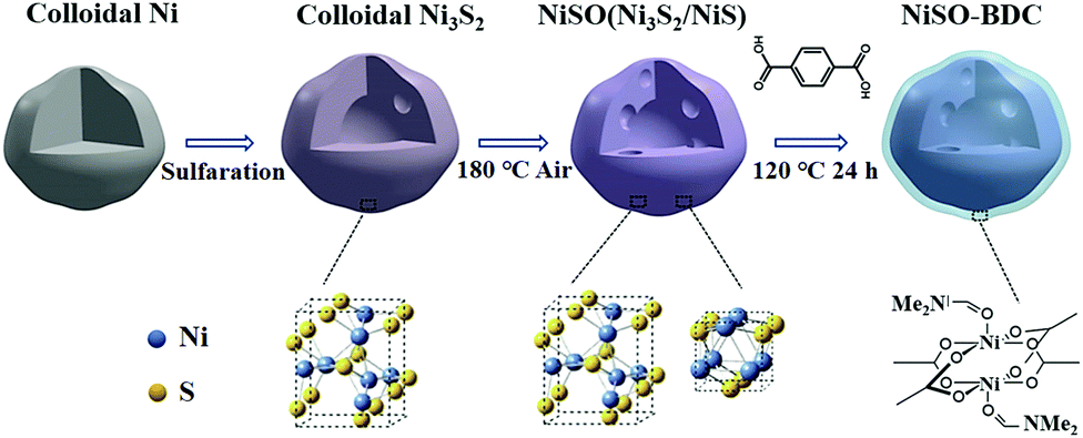 | ||
| Scheme 5 Schematic illustration of the preparation of Ni-BDC-modified Ni3S2/NiS (NiSO-BDC) hollow nanoparticles. Reprinted with permission from (ref. 126). Copyright (2019) American Chemical Society. | ||
MOFs can also act as a support to toggle MNPs and strategies have been developed for loading of MNPs onto MOF particles’ surface. Gao et al.127 systematically loaded ultralow quantities of Fe2O3 particles on to the MOF particle surface in controllable ratios. They reproduced the Ni-MOF-74 containing linker with uncoordinating hydroxyl groups. Following unique and fast “phenol-iron” surface reactions, Fe2O3 particles were attached on to the surfaces of Ni-MOF-74 particles in different % amounts. Upon careful electrochemical analysis, the optimized OER catalyst was found to be 0.6 wt% Fe2O3@Ni-MOF-74 composite.
In a different approach, Zhang et al.128 exfoliated inorganic CoFeOx nanoparticle embedded polycobalt benzimidazole monolayered nanosheets (M-PCBN) out of PCB (polycobalt benzimidazole) analogous framework. Systematic structural characterization revealed that MNP-MOF interfacial Co displays higher valency with changed 3d electronic configuration compared to CoN4 from the framework part and was correlated to the enhanced activity, which was also supported by DFT calculations. Though these materials are broadly classified into different categories for convenience of the reader, there are a few isolated cases which stay in the borderline of these individual classes. One such instance of a three component system was reported by Srinivas et al., where FeNi3–Fe3O4 NPs were anchored on to NiFex-MOF nanosheets and the CNT matrix (FeNi3–Fe3O4 NPs/MOF-CNT). Owing to synergistic interactions among all composite components, it showed excellent overall water splitting activity that surpassed the performance of commercially available electrocatalysts (Pt/C and RuO2).129
3e. Metal/metal oxide supported surface-coordinated metal–organic framework thin films (SURMOFs)
Fabrication of MOF-based composites with conducting substrates, like carbon materials and/or MNPs, has opened up new aspects of designing MOF-based OER catalysts but they are coming up with their own challenges. In the majority of cases, the active catalysts, either being drop casted on to the electrode surface in its native dilute colloidal form (which may leach out) or with binders like Nafion (which insulates and dilutes active sample besides masking pores from reactants), lead to hampering of the efficiency of the catalyst. It showed the dire need of fabricating binder free electrode materials which strongly bind to current collectors with uniform arrangement to minimize issues, related to particle grain boundary. There have been different methods, like direct growth/deposition, layer-by-layer deposition and electrochemical deposition on conducting substrates, like FTO, metal plates and/or porous metal foams even occasionally on to GC active surfaces etc.Working in this direction, a Prussian blue-type cobalt hexacyanoferrate (CoHCF) was fabricated on an FTO (fluoride-doped tin oxide) coated glass electrode by Pintado et al.,130 following electrochemical methods. The stepwise procedure involves electroplating of a thin layer of cobalt metal which was later treated electrochemically in the presence of [FeIII(CN)6]3− leading to a Co–Fe Prussian blue modified FTO electrode. The modified electrode could hold its activity for an extended period (even for weeks), without considerable drop in its efficiency.117
Owing to the ability to maximize accessible catalytic sites and decreased ion transfer distances favoring effective electrical conductivity, it is found to be advantageous to use metal foam type porous conducting substrates to grow/deposit MOFs. The intrinsic spongy texture of these foams allows the fabrication of more efficient and hierarchical porous materials in combination with MOFs with catalytically active sites. Zhao et al. supplemented this fact that thin film-based electrodes exhibit superior electrocatalytic activity over electrodes with bulk material; and films deposited on porous materials show better OER activity over nonporous electrodes.34 Their studies concluded that the bulk MOF possessing GC showed inferior activity in comparison to GC with ultrathin MOF nanosheets of NiCo-MOF (NiCo-UMOFN) (Fig. 4a). On the other hand, NiCo-UMOFN deposited Cu foam exhibited better catalytic activity over GC.
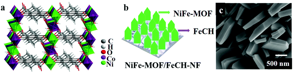 | ||
| Fig. 4 (a) The overall crystal structure of ultrathin MOF nanosheets of NiCo-MOF (NiCo-UMOFNs), with three coordination structural layers. Reprinted with permission from (ref. 34). Copyright (2016) Springer Nature. (b) A representative diagram of the fabrication of NiFe-MOF/FeCH-NF. (c) SEM image of NiFe-MOF/FeCH-NF. Adapted with permission from ref. 133 with the permission of The Royal Society of Chemistry. | ||
There are ample examples, where metal foams can act as sacrificial metal substrates to fabricate mixed metal MOF thin films. Ye et al. demonstrated that two dimensional nanosheet arrays of Co/Ni-based mixed MOF (NiCo-9AC-AD) with controllable and measured composition of Ni0.3Co0.7-9AC-AD/NF were grown on nickel foam (NF) following a simple solvothermal procedure.131 Systematic electrocatalytic analysis concluded that, the presence of ultrathin nano sheets and synergic interactions between Ni/Co catalytic sites resulted in the excellent OER and HER activity. Similarly, Ling et al.132 fabricated Fe2Ni MOF/NF (Fe2Ni-MIL-88B MOF on nickel foam) and explained its superior electrocatalytic activity. In another instance, NF (nickel foam) was demonstrated to act as a support for iron carbonate hydroxide nanosheets (FeCH NS) which was the sacrificial template for Fe/Ni MOF fabrication (Fig. 4b and c).133
The sacrificial template not only releases iron ions for MOF fabrication, it also slows down the release of Ni ions, and in turn, controls the composition of the thin film. Additionally, unreacted FeCH NS also contributes synergistically in boosting the catalytic activity of the resultant electrode material (NiFe-MOF/FeCH-NF). Likewise, there are also bimetallic alloys employed for metal foam supported MOF fabrication.
In a recent report, Huang et al. have shown that CoNi MOF nano arrays (CoNi-MOFNA) can be grown on a CoNi alloy following an in situ self-dissociation-assembly (SDA) synthetic strategy.134 The fabricated material with ultrathin nano arrays, constructed of a synergistically acting bimetallic system having unsaturated coordination sites, shows outstanding OER activity compared to commercially available RuO2 standard. Besides, Ye et al. reported a borderline multicomponent Fe-MOF/NF composite with Pt quantum dots (Pt QDs) incorporated into Fe-MOF nanosheet arrays/shells, that were supported on a nickel foam (Pt QDs@Fe-MOF/NF). This composite, on thorough catalytic analysis, showed excellent water splitting activity with good stability which was attributed to enhanced electron transfer rate by porous Pt QDs@MOF core–shell structure.135Table 2 compares the OER activities of MOF-based hybrid composites.
| Catalyst | Overpotential ηx (mV) x = current density (mA cm−2) | pH | Ref. |
|---|---|---|---|
| (GO 8 wt%) Cu-MOF | η 2 = 110 | <1 | 120 |
| CoHCF | η 1 = 400 | 7 | 130 |
| PCN-224/MWCNT | η 2 = 510 | 9.2 | 118 |
| 3D Gr/Ni-MOF | η 10 = 370 | 13 | 119 |
| Co-MOF@CNTs (5 wt%) | η 57 = 440 | 14 | 121 |
| NiSO-BDC | η 10 = 298 | 14 | 126 |
| 0.6 wt% Fe2O3@Ni-MOF-74 | η 10 = 264 | 14 | 127 |
| M-PCBN | η 10 = 232 | 14 | 128 |
| FeNi3–Fe3O4 NPs/MOF-CNT | η 10 = 234 | 14 | 129 |
| NiCo-UMOFNs/Cu foam | η 10 = 189 | 14 | 34 |
| Ni0.3Co0.7-9AC-AD/NF | η 100 = 350 | 14 | 131 |
| Fe2Ni MOF/NF | η 10 = 222 | 14 | 132 |
| NiFe-MOF/FeCH-NF | η 10 = 200 | 14 | 133 |
| CoNi-MOFNA | η 10 = 215 | 14 | 134 |
| Pt QDs@Fe-MOF/NF | η 100 = 191 | 14 | 135 |
4. Hybrid materials derived by pyrolysis of MOFs
As discussed in earlier sections, designing and structural engineering of MOFs and their hybrid composites have been definitely one of the finest approaches in fabricating MOF-based electrocatalysts for OER applications. However, the applicability of MOFs is not only limited to their native or hybrid forms. MOF derivatization via thermal annealing and graphitization established a systematic approach towards generation of metal oxide/metal sulfide/metal phosphide/metal nanoparticle, etc. embedded, highly conducting graphitic carbon material. Although, most of these materials lose the characteristic structure of the parent MOFs due to destruction of the framework by thermal treatment, but it is a notable approach to develop MOF derived OER electrocatalysts. One such OER electrocatalyst synthesized by annealing of a Co based MOF under air, was reported by Gong et al., where the active unit was Co3O4.136 Apart from this, carbonization (under N2, H2, He),137 thermal phosphidization, thermal sulphization, etc., can also result in further functional tuning. Employment of these techniques can help in the construction of various interesting structures, like functionalized carbon nano tubes,138 metal oxides embedded amorphous carbon matrix, porous nano-cages,139 double shell nano cages,140etc., which can act as OER electrocatalysts. Combination of chemical etching, metal ion doping, hetero-atom doping and guest incorporation along with thermal treatment can result into enhanced functionality and stability. Most of these materials are reported to have high efficiency for OER electrocatalysis in basic pH. However, in the true sense, these thermally derived materials using MOF as a precursor cannot be termed as MOFs, and thus, are beyond the scope of this article. In recent years, a handful of comprehensive and informative reviews have discussed and summarized the recent progress of thermally derived C–N materials from MOFs and their application in the field of electrocatalysis.18,27,47,49,68,141–143Future scope of MOFs for OER electrocatalysis
Some of the early reports on MOF-based OER electrocatalysts were associated with a few apparent shortcomings concerning the efficiency and/or stability of the catalysts. The design and fabrication of multi-metallic MOFs were found to be the notable strategic developments to evade these drawbacks and metalloligand based catalysis was one of the systematic and easiest ways to achieve that. In such systems, the metal center of the metalloligands can act as the catalytic center, while the metal node provides mechanical support. Incorporation of multiple metal ions in a MOF can also positively affect the OER catalytic efficiency by increasing the electrochemically active surface area (ECSA). This helps the system to achieve efficiency by increasing the number of coordinatively unsaturated metal sites in the framework, which then becomes accessible for catalysis. The performance of a MOF-based thin film as a catalyst largely depends upon the rate of mass transport and the electronic charge conduction. Unless a MOF-based catalyst possesses satisfactory charge transport, only a few layers of a MOF, adjacent to the electrode will be electrochemically active and can behave as a catalyst. On the other hand, to and fro diffusion of the substrate and products is essential in order to operate all the catalytically active sites of a MOF for any catalysis. Redox active metal node-containing thin layer MOFs can perform charge transport more efficiently than similar redox inactive MOFs, by a charge hopping mechanism.144 Similarly, MOFs having soft–soft interaction between the metal nodes and organic linkers, supramolecular π–π interaction, composites with host–guest interaction145 and MOFs with high pore size59 can be a good carrier of charge. However, the combination of these desired features with the other essential requirements e.g., high stability under operational conditions and high activity of the catalytic species, requires reticular design strategies.Strategies, like introducing a guest into a pristine framework to yield guest@MOF, have been developed to fabricate MOF-based catalytic systems. Depending upon the nature of the guest species, it can increase the charge transport146 of a catalytically active MOF framework. On the other hand, a catalytically active guest material can be incorporated inside a robust catalytically inactive MOF matrix to enhance the stability of the guest species and perform catalysis. These host–guest materials provide high scope for the modification of the electrocatalytic activity of the material by fine tuning the microenvironment around the guest species. Based on the recent works of our research group, it can be said that exploring the interfacial chemistry of different materials/molecules–MOF host–guest systems can result in better understanding of the structure–function relationship of the composite. Given its other merits, along with its ability to combine the efficiency of molecular catalysts and the robustness and stability of MOFs, a detailed investigation of such guest@MOF species would be interesting and might be of immense importance for the future design of effective electrocatalysts for clean energy applications. On the other hand, there are other candidates like MOF-based metal nanoparticle composites and core–shell structures, where the activity of the catalytic center is vastly influenced by the surrounding MOF which serves the dual benefit of stabilizing the catalyst as well as providing a porous support.
Furthermore, in order to tackle the issue of low electronic conductivity of most of the MOF-based OER electrocatalysts, there has been a rise in the use of conducting carbons (CNT, rGO, etc.), FTO, metal foams (Ni-, Cu-, etc.) and layered double hydroxides (LDH) as a sacrificial template, to grow mono- and/or multi-metallic MOF nanoparticles. Various composites employing different guest species embedded into MOF thin films were reported to have one of the lowest overpotentials. Bearing the above merits in mind, designing and executing MOF-based composite material fabrication with other conducting and/or active catalytic species would be an effective strategy.
Thermally derived materials from MOFs presented an excellent scope to lower the inherent resistance and the overpotential requirement for the OER. The scope of reductive carbonization, oxidative calcination, phosphidation at an elevated temperature and many more reactions of graphitic carbons can lead to the generation of materials with diverse functionalities and with enhanced physical and chemical properties. This approach provides a huge scope of exploring various MOFs and MOF derivatives to prepare efficient and robust electrocatalysts for the OER.
This discussion clearly depicts the fact that various case specific modifications of MOFs to derive OER catalysts have led to a situation where generalizations can be formulated based on the structure–function relationship of MOFs and MOF-derivatives. Careful observation suggests that a combination of the above-mentioned strategies can be highly effective to prepare better catalysts. For example, growing a thin film of guest@MOF composite on an electrode surface can result in a high TOF and low overpotential requirement for electrochemical OER. In various reports (a) metal ion-based engineering, (b) MNP@MOF, (c) MOF grown on electrode, etc. have been observed to be useful to prepare OER catalysts in combination with thermal treatment. To put it simply, each component of the MOF-derived composite has its own significant task and they all interact synergistically to enhance the overall electrocatalytic activity.
Conclusion
Thus, to conclude, it can be said that the MOFs hold high potential towards application in the field of electrochemical OER mainly because of their large surface area, pore volume, complex structure, and wide scope of functional tuning by means of structural modifications. Because of the huge range of choice of metal nodes, organic linkers and guest species, MOFs and MOF-derived materials hold a plethora of possibilities, very few of which have been explored. Moreover, since most of the MOFs are crystalline, it is easier to study the structure function relationships of the electrocatalysts. Looking back at the advancements made in this field in the last few years, we believe that the future of MOF-based electrocatalyst is beyond the realm of just MOFs. It requires a combination of various fields and research at the interface of different materials to ultimately prepare hybrid composites which can exploit the advantages of MOFs and their derivatives, leaving behind their limitations.Conflicts of interest
There are no conflicts to declare.Acknowledgements
We thank SERB, DST, Government of India (Project No. EMR/2017/002971) for the financial support. S. Mukhopadhyay thanks DST-INSPIRE, New Delhi, India and O. Basu thanks UGC, New Delhi, India for their fellowships. R. Nasani thanks UGC for Dr D S Kothari Postdoctoral fellowship (F.4-2/2006 (BSR)/CH/18-19/0032). We also thank DST-FIST, UGC-SAP, and UPE-II for the facilities. This work is also supported by UGC-BSR-Mid-Career Award project (project No. 19-232/ 2019(BSR)).References
- P. E. Brockway, A. Owen, L. I. Brand-Correa and L. Hardt, Nat. Energy, 2019, 4, 612–621 CrossRef.
- D. Millstein, R. Wiser, M. Bolinger and G. Barbose, Nat. Energy, 2017, 2, 1–10 CrossRef.
- B. M. Hunter, H. B. Gray and A. M. Müller, Chem. Rev., 2016, 116, 14120–14136 CrossRef.
- W. Ruttinger and G. C. Dismukes, Chem. Rev., 1997, 97, 1–24 CrossRef.
- C. Gao, J. Wang, H. Xu and Y. Xiong, Chem. Soc. Rev., 2017, 46, 2799–2823 RSC.
- T. J. Meyer, M. V. Sheridan and B. D. Sherman, Chem. Soc. Rev., 2017, 46, 6148–6169 RSC.
- J. Li, R. Güttinger, R. Moré, F. Song, W. Wan and G. R. Patzke, Chem. Soc. Rev., 2017, 46, 6124–6147 RSC.
- Y. Xu, Q. Li, H. Xue and H. Pang, Coord. Chem. Rev., 2018, 376, 292–318 CrossRef.
- J. G. McAlpin, T. A. Stich, W. H. Casey and R. D. Britt, Coord. Chem. Rev., 2012, 256, 2445–2452 CrossRef.
- F. Kuttassery, S. Mathew, S. N. Remello, A. Thomas, K. Sano, Y. Ohsaki, Y. Nabetani, H. Tachibana and H. Inoue, Coord. Chem. Rev., 2018, 377, 64–72 CrossRef.
- B. Singh and A. Indra, Chem. – Asian J., 2020, 607–623 CrossRef.
- C. Freire, D. M. Fernandes, M. Nunes and V. K. Abdelkader, ChemCatChem, 2018, 10, 1703–1730 CrossRef.
- B. D. McCarthy, A. M. Beiler, B. A. Johnson, T. Liseev, A. T. Castner and S. Ott, Coord. Chem. Rev., 2020, 406, 213137 CrossRef.
- Q. Wang and D. Astruc, Chem. Rev., 2020, 120, 1438–1511 CrossRef.
- A. Bavykina, N. Kolobov, I. S. Khan, J. A. Bau, A. Ramirez and J. Gascon, Chem. Rev., 2020, 120, 8468–8535 CrossRef.
- J. Liu, S. Hou, W. Li, A. S. Bandarenka and R. A. Fischer, Chem. – Asian J., 2019, 14, 3474–3501 CrossRef.
- Q. Jiang, C. Zhou, H. Meng, Y. Han, X. Shi, C. Zhan and R. Zhang, J. Mater. Chem. A, 2020, 8, 15271–15301 RSC.
- H. F. Wang, L. Chen, H. Pang, S. Kaskel and Q. Xu, Chem. Soc. Rev., 2020, 49, 1414–1448 RSC.
- A. Dhakshinamoorthy, M. Alvaro and H. Garcia, Chem. Commun., 2012, 48, 11275–11288 RSC.
- L. Kong, M. Zhong, W. Shuang, Y. Xu and X.-H. Bu, Chem. Soc. Rev., 2020, 49, 2378–2407 RSC.
- S. Jin, ACS Energy Lett., 2019, 4, 1443–1445 CrossRef.
- J. D. Blakemore, R. H. Crabtree and G. W. Brudvig, Chem. Rev., 2015, 115, 12974–13005 CrossRef.
- M. Zhao, S. Ou and C. De Wu, Acc. Chem. Res., 2014, 47, 1199–1207 CrossRef.
- P. Q. Liao, J. Q. Shen and J. P. Zhang, Coord. Chem. Rev., 2018, 373, 22–48 CrossRef.
- Q. Shao, J. Yang and X. Huang, Chem. – Eur. J., 2018, 24, 15143–15155 CrossRef CAS.
- X. Hu and S. Dong, J. Mater. Chem., 2008, 18, 1279–1295 RSC.
- Y. Z. Chen, R. Zhang, L. Jiao and H. L. Jiang, Coord. Chem. Rev., 2018, 362, 1–23 CrossRef CAS.
- P. Garrido-Barros, C. Gimbert-Suriñach, R. Matheu, X. Sala and A. Llobet, Chem. Soc. Rev., 2017, 46, 6088–6098 RSC.
- Q. Ren, H. Wang, X. F. Lu, Y. X. Tong and G. R. Li, Adv. Sci., 2018, 5, 1700515 CrossRef.
- C. A. Downes and S. C. Marinescu, ChemSusChem, 2017, 10, 4374–4392 CrossRef CAS.
- M. Shamsipur and A. Pashabadi, Coord. Chem. Rev., 2018, 374, 153–172 CrossRef CAS.
- H. Zhu, D. Liu, D. Zou and J. Zhang, J. Mater. Chem. A, 2018, 6, 6130–6154 RSC.
- W. Li, S. Watzele, H. A. El-Sayed, Y. Liang, G. Kieslich, A. S. Bandarenka, K. Rodewald, B. Rieger and R. A. Fischer, J. Am. Chem. Soc., 2019, 141, 5926–5933 CrossRef CAS.
- S. Zhao, Y. Wang, J. Dong, C. T. He, H. Yin, P. An, K. Zhao, X. Zhang, C. Gao, L. Zhang, J. Lv, J. Wang, J. Zhang, A. M. Khattak, N. A. Khan, Z. Wei, J. Zhang, S. Liu, H. Zhao and Z. Tang, Nat. Energy, 2016, 1, 1–10 Search PubMed.
- M. B. Solomon, T. L. Church and D. M. D’Alessandro, CrystEngComm, 2017, 19, 4049–4065 RSC.
- A. H. Chughtai, N. Ahmad, H. A. Younus, A. Laypkov and F. Verpoort, Chem. Soc. Rev., 2015, 44, 6804–6849 RSC.
- H. Lv, Y. V. Geletii, C. Zhao, J. W. Vickers, G. Zhu, Z. Luo, J. Song, T. Lian, D. G. Musaev and C. L. Hill, Chem. Soc. Rev., 2012, 41, 7572–7589 RSC.
- W. Cheng, X. Zhao, H. Su, F. Tang, W. Che, H. Zhang and Q. Liu, Nat. Energy, 2019, 4, 115–122 CrossRef CAS.
- C. Singh, I. Liberman, R. Shimoni, R. Ifraemov and I. Hod, J. Phys. Chem. Lett., 2019, 10, 3630–3636 CrossRef CAS.
- D. Gao, I. Trentin, L. Schwiedrzik, L. González and C. Streb, Molecules, 2020, 25, 1–20 Search PubMed.
- X. Zhou, T. Zhang, C. W. Abney, Z. Li and W. Lin, ACS Appl. Mater. Interfaces, 2014, 6, 18475–18479 CrossRef CAS.
- K. Chen and C. Wu, Coord. Chem. Rev., 2019, 378, 445–465 CrossRef CAS.
- Q. Y. Li, L. Zhang, Y. X. Xu, Q. Li, H. Xue and H. Pang, ACS Sustainable Chem. Eng., 2019, 7, 5027–5033 CrossRef CAS.
- B. A. Johnson, A. Bhunia and S. Ott, Dalton Trans., 2017, 46, 1382–1388 RSC.
- S. Lin, P. M. Usov and A. J. Morris, Chem. Commun., 2018, 54, 6965–6974 RSC.
- S. Wang, Y. Hou, S. Lin and X. Wang, Nanoscale, 2014, 6, 9930–9934 RSC.
- W. Xia, A. Mahmood, R. Zou and Q. Xu, Energy Environ. Sci., 2015, 8, 1837–1866 RSC.
- J. Juan-Alcañiz, J. Gascon and F. Kapteijn, J. Mater. Chem., 2012, 22, 10102–10119 RSC.
- A. Mahmood, W. Guo, H. Tabassum and R. Zou, Adv. Energy Mater., 2016, 6, 1–26 Search PubMed.
- A. Dhakshinamoorthy and H. Garcia, Chem. Soc. Rev., 2012, 41, 5262–5284 RSC.
- J. Liu and C. Wöll, Chem. Soc. Rev., 2017, 46, 5730–5770 RSC.
- M. Batool, S. Ibrahim, B. Iqbal, S. Ali, A. Badshah, S. Abbas, D. R. Turner and M. A. Nadeem, Electrochim. Acta, 2019, 298, 248–253 CrossRef CAS.
- X.-F. Lu, L.-F. Gu, J.-W. Wang, J.-X. Wu, P.-Q. Liao and G.-R. Li, Adv. Mater., 2017, 29, 1604437 CrossRef.
- H. B. Aiyappa, J. Masa, C. Andronescu, M. Muhler, R. A. Fischer and W. Schuhmann, Small Methods, 2019, 3, 1800415 CrossRef.
- A. M. Ullman, J. W. Brown, M. E. Foster, F. Léonard, K. Leong, V. Stavila and M. D. Allendorf, Inorg. Chem., 2016, 55, 7233–7249 CrossRef CAS.
- Y. Xue, S. Zheng, H. Xue and H. Pang, J. Mater. Chem. A, 2019, 7, 7301–7327 RSC.
- R. Zhu, J. Ding, Y. Xu, J. Yang, Q. Xu and H. Pang, Small, 2018, 14, 1803576 CrossRef.
- B. A. Johnson, A. M. Beiler, B. D. McCarthy and S. Ott, J. Am. Chem. Soc., 2020, 142, 11941–11956 CrossRef CAS.
- M. Cai, Q. Loague and A. J. Morris, J. Phys. Chem. Lett., 2020, 11, 702–709 CrossRef CAS.
- S. Bose, J. Debgupta, R. M. Ramsundar and S. K. Das, Chem. – Eur. J., 2017, 23, 8051–8057 CrossRef CAS.
- C. Singh, S. Mukhopadhyay and S. K. Das, Inorg. Chem., 2018, 57, 6479–6490 CrossRef CAS.
- A. P. Wight and M. E. Davis, Chem. Rev., 2002, 102, 3589–3614 CrossRef CAS.
- C. Wang, Z. Xie, K. E. Dekrafft and W. Lin, J. Am. Chem. Soc., 2011, 133, 13445–13454 CrossRef CAS.
- O. Shekhah, J. Liu, R. A. Fischer and C. Wöll, Chem. Soc. Rev., 2011, 40, 1081–1106 RSC.
- J. D. Evans, C. J. Sumby and C. J. Doonan, Chem. Soc. Rev., 2014, 43, 5933–5951 RSC.
- Q. L. Zhu and Q. Xu, Chem. Soc. Rev., 2014, 43, 5468–5512 RSC.
- K. Meyer, M. Ranocchiari and J. A. Van Bokhoven, Energy Environ. Sci., 2015, 8, 1923–1937 RSC.
- N. Cheng, L. Ren, X. Xu, Y. Du and S. X. Dou, Adv. Energy Mater., 2018, 8, 1–21 Search PubMed.
- Y. Yan, T. He, B. Zhao, K. Qi, H. Liu and B. Y. Xia, J. Mater. Chem. A, 2018, 6, 15905–15926 RSC.
- C. Guan, X. Liu, W. Ren, X. Li, C. Cheng and J. Wang, Adv. Energy Mater., 2017, 7, 1–8 Search PubMed.
- X. Li, S. Zheng, L. Jin, Y. Li, P. Geng, H. Xue, H. Pang and Q. Xu, Adv. Energy Mater., 2018, 8, 1–25 Search PubMed.
- H. R. Moon, D. W. Lim and M. P. Suh, Chem. Soc. Rev., 2013, 42, 1807–1824 RSC.
- Q. Yang, Q. Xu and H. L. Jiang, Chem. Soc. Rev., 2017, 46, 4774–4808 RSC.
- S. K. Bhardwaj, N. Bhardwaj, R. Kaur, J. Mehta, A. L. Sharma, K. H. Kim and A. Deep, J. Mater. Chem. A, 2018, 6, 14992–15009 RSC.
- O. Basu, S. Mukhopadhyay and S. K. Das, J. Chem. Sci., 2018, 130, 1–15 CrossRef CAS.
- X. F. Lu, P. Q. Liao, J. W. Wang, J. X. Wu, X. W. Chen, C. T. He, J. P. Zhang, G. R. Li and X. M. Chen, J. Am. Chem. Soc., 2016, 138, 8336–8339 CrossRef CAS.
- Y. Gong, H. F. Shi, P. G. Jiang, W. Hua and J. H. Lin, Cryst. Growth Des., 2014, 14, 649–657 CrossRef CAS.
- S. Gutiérrez-Tarriño, J. L. Olloqui-Sariego, J. J. Calvente, M. Palomino, G. M. Espallargas, J. L. Jorda, F. Rey and P. Oña-Burgos, ACS Appl. Mater. Interfaces, 2109, 11, 46658–46665 CrossRef.
- S. Ibrahim, K. Shehzadi, B. Iqbal, S. Abbas, D. R. Turner and M. A. Nadeem, J. Colloid Interface Sci., 2019, 545, 269–275 CrossRef CAS.
- J. Jiang, L. Huang, X. Liu and L. Ai, ACS Appl. Mater. Interfaces, 2017, 9, 7193–7201 CrossRef CAS.
- X. Wang, B. Li, Y.-P. Wu, A. Tsamis, H.-G. Yu, S. Liu, J. Zhao, Y.-S. Li and D.-S. Li, Inorg. Chem., 2020, 59, 4764–4771 CrossRef CAS.
- H. Dong, X. Zhang, X.-C. Yan, Y.-X. Wang, X. Sun, G. Zhang, Y. Feng and F.-M. Zhang, ACS Appl. Mater. Interfaces, 2019, 11, 45080–45086 CrossRef CAS.
- P. M. Usov, S. R. Ahrenholtz, W. A. Maza, B. Stratakes, C. C. Epley, M. C. Kessinger, J. Zhu and A. J. Morris, J. Mater. Chem. A, 2016, 4, 16818–16823 RSC.
- K. Maity, K. Bhunia, D. Pradhan and K. Biradha, ACS Appl. Mater. Interfaces, 2017, 9, 37548–37553 CrossRef CAS.
- J. Gao, J. Cong, Y. Wu, L. Sun, J. Yao and B. Chen, ACS Appl. Energy Mater., 2018, 1, 5140–5144 CAS.
- X. Zhao, B. Pattengale, D. Fan, Z. Zou, Y. Zhao, J. Du, J. Huang and C. Xu, ACS Energy Lett., 2018, 3, 2520–2526 CrossRef CAS.
- Y. Duan, S. Sun, S. Xi, X. Ren, Y. Zhou, G. Zhang, H. Yang, Y. Du and Z. J. Xu, Chem. Mater., 2017, 29, 10534–10541 CrossRef CAS.
- B. S. Yeo and A. T. Bell, J. Am. Chem. Soc., 2011, 133, 5587–5593 CrossRef CAS.
- F. Zheng, D. Xiang, P. Li, Z. Zhang, C. Du, Z. Zhuang, X. Li and W. Chen, ACS Sustainable Chem. Eng., 2019, 7, 9743–9749 CrossRef CAS.
- D. Zhang, R. Huang, H. Xie, R. Li, X. Liu, M. Pan and Y. Lei, Chem. Pap., 2020, 74, 2775–2784 CrossRef CAS.
- Z. Wan, D. Yang, J. Chen, J. Tian, T. T. Isimjan and X. Yang, ACS Appl. Nano Mater., 2019, 2, 6334–6342 CrossRef CAS.
- W. Li, W. Fang, C. Wu, K. N. Dinh, H. Ren, L. Zhao, C. Liu and Q. Yan, J. Mater. Chem. A, 2020, 8, 3658–3666 RSC.
- J. Xu, Z. Xiao and X. Jia, ACS Sustainable Chem. Eng., 2019, 7, 6629–16639 CrossRef.
- X. J. Bai, Y. N. Li, X. M. Yang, M. Y. Zhang, L. Shao, B. Zhang, T. Q. Wang, X. M. Zhang, L. Y. Zhang, Y. Fu and W. Qi, Chem. Commun., 2019, 55, 9343–9346 RSC.
- Q. Qian, Y. Li, Y. Liu, L. Yu and G. Zhang, Adv. Mater., 2019, 31, 1–8 Search PubMed.
- Y. Gong, H. F. Shi, Z. Hao, J. L. Sun and J. H. Lin, Dalton Trans., 2013, 42, 12252–12259 RSC.
- Y. Gong, Z. Hao, J. Meng, H. Shi, P. Jiang, M. Zhang and J. Lin, ChemPlusChem, 2014, 79, 266–277 CrossRef CAS.
- A. Bhunia, B. A. Johnson, J. Czapla-Masztafiak, J. Sá and S. Ott, Chem. Commun., 2018, 54, 7770–7773 RSC.
- Z. Xue, Y. Li, Y. Zhang, W. Geng, B. Jia, J. Tang, S. Bao, H. P. Wang, Y. Fan, Z. wen Wei, Z. Zhang, Z. Ke, G. Li and C. Y. Su, Adv. Energy Mater., 2018, 8, 1801564 CrossRef.
- D. Han, K. Huang, X. Li, M. Peng, L. Jing, B. Yu, Z. Chen and D. Qin, RSC Adv., 2019, 9, 33890–33897 RSC.
- W. He, H.-M. Gao, R. Shimoni, Z.-Y. Lu and I. Hod, ACS Appl. Energy Mater., 2019, 2, 2138–2148 CrossRef CAS.
- A. Bucci, S. S. Mondal, V. Martin-Diaconescu, A. Shafir and J. Lloret-Fillol, ACS Appl. Energy Mater., 2019, 2, 8930–8938 CrossRef CAS.
- T. Ishida, M. Nagaoka, T. Akita and M. Haruta, Chem. – Eur. J., 2008, 14, 8456–8460 CrossRef CAS.
- T. Ishida, N. Kawakita, T. Akita and M. Haruta, Gold Bull., 2009, 42, 267–274 CrossRef CAS.
- S. B. Kalidindi, D. Esken and R. A. Fischer, Chem. – Eur. J., 2011, 17, 6594–6597 CrossRef CAS.
- J. Guo, X. Zhang, Y. Sun, L. Tang, Q. Liu and X. Zhang, ACS Sustainable Chem. Eng., 2017, 5, 11577–11583 CrossRef CAS.
- B. Nepal and S. Das, Angew. Chem., Int. Ed., 2013, 52, 7224–7227 CrossRef CAS.
- P. Manna, J. Debgupta, S. Bose and S. K. Das, Angew. Chem., Int. Ed., 2016, 55, 2425–2430 CrossRef CAS.
- S. Mukhopadhyay, J. Debgupta, C. Singh, A. Kar and S. K. Das, Angew. Chem., Int. Ed., 2018, 57, 1918–1923 CrossRef CAS.
- V. K. Abdelkader-Fernández, Diana M. Fernandes, S. S. Balula, L. Cunha-Silva and C. Freire, ACS Appl. Energy Mater., 2020, 3, 2925–2934 CrossRef.
- S. Mukhopadhyay, O. Basu, A. Kar and S. K. Das, Inorg. Chem., 2020, 59, 472–483 CrossRef CAS.
- S. Mukhopadhyay, O. Basu and S. K. Das, ChemCatChem DOI:10.1002/cctc.202000804.
- B. V. K. J. Schmidt, Macromol. Rapid Commun., 2020, 41, 1900333 CrossRef CAS.
- K. E. Ramohlola, G. R. Monana, M. J. Hato, K. D. Modibane, K. M. Molapo, M. Masikini, S. B. Mduli and E. I. Iwuoha, Composites, Part B, 2018, 137, 129–139 CrossRef CAS.
- K. E. Ramohlola, M. Masikini, S. B. Mdluli, G. R. Monama, M. J. Hato, K. M. Molapo, E. I. Iwuoha and K. D. Modibane, Int. J. Electrochem. Sci., 2017, 12, 4392–4405 CrossRef CAS.
- Y. Zhang, X. Feng, S. Yuan, J. Zhou and B. Wang, Inorg. Chem. Front., 2016, 3, 896–909 RSC.
- W. J. Dang, Y. Q. Shen, M. Lin, H. Jiao, L. Xu and Z. L. Wang, J. Alloys Compd., 2019, 792, 69–76 CrossRef CAS.
- S. Sohrabi, S. Dehghanpour and M. Ghalkhani, J. Mater. Sci., 2018, 53, 3624–3639 CrossRef CAS.
- A. Xie, J. Du, F. Tao, Y. Tao, Z. Xiong, S. Luo, X. Li and C. Yao, Electrochim. Acta, 2019, 305, 338–348 CrossRef CAS.
- M. Jahan, Z. Liu and K. P. Loh, Adv. Funct. Mater., 2013, 23, 5363–5372 CrossRef CAS.
- Y. Fang, X. Li, F. Li, X. Lin, M. Tian, X. Long, X. An, Y. Fu, J. Jin and J. Ma, J. Power Sources, 2016, 326, 50–59 CrossRef CAS.
- L. Zhao, B. Dong, S. Li, L. Zhou, L. Lai, Z. Wang, S. Zhao, M. Han, K. Gao, M. Lu, X. Xie, B. Chen, Z. Liu, X. Wang, H. Zhang, H. Li, J. Liu, H. Zhang, X. Huang and W. Huang, ACS Nano, 2017, 11, 5800–5807 CrossRef CAS.
- Y. Wen, Z. Wei, C. Ma, X. Xing, Z. Li and D. Luo, Nanomaterials, 2019, 9, 775 CrossRef CAS.
- X. Deng and H. Tüysüz, ACS Catal., 2014, 4, 3701–3714 CrossRef CAS.
- B. Chakraborty and I. A. Weinstock, Coord. Chem. Rev., 2019, 382, 85–102 CrossRef CAS.
- J. Wang and H. C. Zeng, ACS Appl. Mater. Interfaces, 2019, 11, 23180–23191 CrossRef CAS.
- Z. Gao, Z. W. Yu, F. Q. Liu, Y. Yu, X. M. Su, L. Wang, Z. Z. Xu, Y. L. Yang, G. R. Wu, X. F. Feng and F. Luo, Inorg. Chem., 2019, 58, 11500–11507 CrossRef CAS.
- W. Zhang, Y. Wang, H. Zheng, R. Li, Y. Tang, B. Li, C. Zhu, L. You, M.-R. Gao, Z. Liu, S.-H. Yu and K. Zhou, ACS Nano, 2020, 14, 1971–1981 CrossRef CAS.
- K. Srinivas, Y. Lu, Y. Chen, W. Zhang and D. Yang, ACS Sustainable Chem. Eng., 2020, 8, 3820–3831 CrossRef CAS.
- S. Pintado, S. Goberna-Ferrón, E. C. Escudero-Adán and J. R. Galán-Mascarós, J. Am. Chem. Soc., 2013, 135, 13270–13273 CrossRef CAS.
- W. Ye, Y. Yang, X. Fang, M. Arif, X. Chen and D. Yan, ACS Sustainable Chem. Eng., 2019, 7, 18085–18092 CrossRef CAS.
- X. Ling, F. Du, Y. Zhang, Y. Shen, T. Li, A. Alsaedi, T. Hayat, Y. Zhou and Z. Zou, RSC Adv., 2019, 9, 33558–33562 RSC.
- J. Du, S. Xu, L. Sun and F. Li, Chem. Commun., 2019, 55, 14773–14776 RSC.
- L. Huang, G. Gao, H. Zhang, J. Chen, Y. Fang and S. Dong, Nano Energy, 2020, 68, 104296 CrossRef CAS.
- B. Ye, R. Jiang, Z. Yu, Y. Hou, J. Huang, B. Zhang, Y. Huang, Y. Zhang and R. Zhang, J. Catal., 2019, 380, 307–317 CrossRef CAS.
- Y. Gong, Z. Xu and H. Pan, ChemistrySelect, 2019, 4, 1131–1137 CrossRef CAS.
- R. Xiang, Y. Duan, C. Tong, L. Peng, J. Wang, S. S. A. Shah, T. Najam, X. Huang and Z. Wei, Electrochim. Acta, 2019, 302, 45–55 CrossRef CAS.
- T. Y. Ma, S. Dai, M. Jaroniec and S. Z. Qiao, J. Am. Chem. Soc., 2014, 136, 13925–13931 CrossRef CAS.
- Y. Hou, J. Li, Z. Wen, S. Cui, C. Yuan and J. Chen, Nano Energy, 2015, 12, 1–8 CrossRef CAS.
- H. Hu, B. Guan, B. Xia and X. W. Lou, J. Am. Chem. Soc., 2015, 137, 5590–5595 CrossRef CAS.
- Q. Shi, S. Fu, C. Zhu, J. Song, D. Du and Y. Lin, Mater. Horiz., 2019, 6, 684–702 RSC.
- J. K. Sun and Q. Xu, Energy Environ. Sci., 2014, 7, 2071–2100 RSC.
- J. Zhang, H. Li, P. Guo, H. Ma and X. S. Zhao, J. Mater. Chem. A, 2016, 4, 8497–8511 RSC.
- L. Sun, C. H. Hendon, S. S. Park, Y. Tulchinsky, R. Wan, F. Wang, A. Walsh and M. Dincă, Chem. Sci., 2017, 8, 4450–4457 RSC.
- S. Lin, P. M. Usov and A. J. Morris, Chem. Commun., 2018, 54, 6965–6974 RSC.
- Y. Kobayashi, B. Jacobs, M. D. Allendorf and J. R. Long, Chem. Mater., 2010, 22, 4120–4122 CrossRef CAS.
| This journal is © The Royal Society of Chemistry 2020 |