 Open Access Article
An in situ LiF-enriched solid electrolyte interphase from CoF2-decorated N-doped carbon for dendrite-free Li metal anodes†
Xiaopan
Jin
a,
Gaoxu
Huang
a,
Xianming
Zhao
a,
Guoli
Chen
a,
Mengjia
Guan
a and
Yongsheng
Li
 *ab
*ab
aLab of Low-Dimensional Materials Chemistry, Key Laboratory for Ultrafine Materials of Ministry of Education, Frontier Science Center of the Materials Biology and Dynamic Chemistry, Shanghai Engineering Research Center of Hierarchical Nanomaterials, School of Materials Science and Engineering, East China University of Science and Technology, Shanghai 200237, China. E-mail: ysli@ecust.edu.cn
bKey Laboratory for Green Processing of Chemical Engineering of Xinjiang Bingtuan, School of Chemistry and Chemical Engineering, Shihezi University, Shihezi 832003, China
First published on 29th March 2023
Abstract
Lithium (Li) metal has shown great potential as the anode for high-energy-density rechargeable batteries due to its ultrahigh theoretical specific capacity and low redox potential. However, the practical application of the Li metal anode is inherently limited by the uncontrollable Li dendrite growth and unstable solid electrolyte interphase (SEI) layer. Herein, a CoF2-decorated N-doped carbon (denoted as CoF2@NC) is synthesized by a convenient fluoridation treatment after the carbonization of ZIF-67 precursor and used as a functional coating on the bare Cu current collector for enabling uniform Li deposition. Due to the lithiophilic properties of the CoF2@NC matrix and the as-generated LiF-enriched SEI layer, the CoF2@NC-modified current collector demonstrates decreased nucleation potential and a more stable Li stripping/plating process. As a result, the symmetric cell with a Li@CoF2@NC/Cu electrode exhibits substantially enhanced cycling stability for 1200 h under the conditions of 1 mA cm−2 and 1 mA h cm−2. Moreover, the assembled LiFePO4 full cell with a Li@CoF2@NC/Cu anode delivers excellent rate performance and cycling stability, endowing high initial discharge capacity (149.3 mA h g−1) and capacity retention (95.45%) after 500 cycles at 1C. This work emphasizes that the synergistic effect of the lithiophilic substrate and robust SEI layer is essential for high-performance Li metal batteries.
Introduction
With the development of portable devices, electric vehicles and smart grids in the world, lithium-ion batteries (LIBs) cannot meet the increasing demand of the market due to the inherent energy-density limitation based on the traditional graphite anodes.1–4 The lithium (Li) metal anode, which possesses the advantages of ultra-high theoretical specific capacity (3860 mA h g−1), low weight (0.534 g cm−3) and low electrochemical potential (−3.04 V versus H+/H2), has been regarded as the most promising alternative to achieve high-energy-density Li secondary batteries.5–7 However, the practical applications of the Li metal anode have been hindered by several challenges, especially the uncontrollable Li dendrite formation and unstable solid electrolyte interphase (SEI) layer owing to the inhomogeneous Li deposition behaviour.2,8 Specifically, Li metal is highly reactive with the liquid electrolyte and chemical reactions can spontaneously occur to form a fragile SEI layer on the surface.9 In addition, the huge volume expansion of the Li anode during the Li stripping/plating process probably causes mechanical stress and tears the fragile native SEI, leading to the exposure of fresh Li to the electrolyte and further consuming the metallic Li.10,11 Even worse, Li dendrites grown from cracks can penetrate the separator and give rise to battery failure, which can also cause battery safety issues.12–14 These obstacles ultimately result in low Coulombic efficiency, short lifespan and even safety hazards of Li metal batteries (LMBs).To accelerate the practical applications of LMBs, considerable efforts have been devoted to overcoming the above-mentioned challenges, such as introducing appropriate electrolyte additives,15–17 manufacturing robust artificial SEI layers,18–20 designing 3D conductive skeletons,21–23 and constructing all-solid-state battery systems.24–27 Among the developed strategies, constructing porous N-doped carbon with excellent Li affinity has been proved to effectively suppress the formation of Li dendrites and prolong the lifespan of LMBs. Recently, metal–organic framework (MOF)-derived porous carbon has received increasing attention in energy storage due to the high specific surface area, structural stability and porous structures.28–31 However, the deterioration of the SEI layer on the carbon substrate during the long-term stripping/plating process leads to relatively limited cycling lifespan of the Li metal anode. Stable and solid SEI layers can prevent fresh lithium from being exposed to the electrolyte and can effectively improve the cycle life and safety performance of the battery.32,33 Generally, lithium fluoride (LiF) is considered to be a chemically and thermodynamically stable component originating from the decomposition of the fluorine-containing electrolyte, which delivers faster ion transportation than the most common Li2CO3 component in the native SEI.34,35 In addition, the presence of LiF/Li2CO3 grain boundaries and the nanoscale nature of LiF could enhance the transportation of Li ions in a LiF-enriched SEI.36,37 Therefore, increasing the LiF content in the SEI layer is a key to stabilizing the interface of Li metal anodes and certainly boosts the lifespan of LMBs.38 However, the preparation of a metal fluoride-modified carbon matrix has been rarely reported in the literature. Polytetrafluoroethylene (PTFE) is a kind of fluorine-containing material with the highest fluorine content (up to 75%) among all fluoropolymers.39 When it is thermally decomposed, PTFE can serve as the spatial condition creator by releasing highly oxidizing fluorine-containing radicals.40 Hence, it is highly desirable to combine the MOF derivation and fluorination strategy to prepare MOF-derived metal fluorides for achieving homogeneous Li deposition of Li metal anodes.
Herein, we design and synthesize CoF2-decorated N-doped carbon (CoF2@NC) through a convenient fluoridation treatment after the carbonation of the ZIF-67 precursor, where PTFE is used as the F source in the fluoridation process. The CoF2@NC is employed as a lithiophilic host for enabling homogeneous Li electrodeposition. Benefitting from the synergetic effect of high lithiophilicity provided by the N-doped carbon and CoF2 nanoparticles and the as-generated LiF-enriched SEI layer, the CoF2@NC-decorated Cu current collector (CoF2@NC/Cu) achieves a decreased nucleation overpotential and uniform Li plating behaviour. Therefore, the Li|Cu cell with the CoF2@NC/Cu substrate exhibits high Coulombic efficiency of ∼96.6% even after 500 cycles and the Li|Li symmetric cell with the Li@CoF2@NC/Cu anode demonstrates improved cycling stability for 1200 h. Moreover, the assembled LiFePO4 full cell with a Li@CoF2@NC/Cu anode delivers excellent rate performance and cycling stability, presenting great potential in the practical application of LMBs.
Results and discussion
Fig. 1a schematically illustrates the synthetic process of the CoF2-decorated N-doped carbon (CoF2@NC), which was fabricated via a facile fluorination treatment after the carbonization of a ZIF-67 precursor. Briefly, rhombic dodecahedral ZIF-67 powder was synthesized through the typical room-temperature reaction of 2-methylimidazole and Co(NO3)2·6H2O in methanol solution. The powder X-ray diffraction (XRD) pattern in Fig. S1a (ESI†) indicates the successful formation of a ZIF-67 crystal structure. Subsequently, the as-obtained ZIF-67 was converted into a carbon framework doped with uniformly distributed Co nanoparticles (Co@NC) through a carbonization process in an inert atmosphere. Meanwhile, the XRD pattern of Co@NC (Fig. S1b, ESI†) confirms the transformation of ZIF-67 into a carbon framework embedded with metallic Co, as demonstrated by the broad diffraction peak of graphitic carbon at around 23° and three characteristic peaks of face-centered-cubic Co phase at 44.2°, 51.5°, and 75.9°, respectively. Then, the CoF2@NC was obtained by a fluoridation etching treatment of Co@NC with PTFE powder as the fluorine source. From the XRD pattern of CoF2@NC (Fig. S1b, ESI†), the peak of graphitic carbon is maintained well, while the peaks assigned to the metallic Co disappeared, implying the possible formation of Co-containing compounds after the fluoridation etching treatment.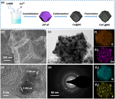 | ||
| Fig. 1 (a) Schematic illustration for the synthesis of CoF2@NC, (b and c) SEM, (d) TEM, (e) high-resolution TEM and (f) elemental mapping images of CoF2@NC. | ||
The morphological features of the resultant ZIF-67, Co@NC and CoF2@NC were characterized by scanning electron microscopy (SEM) and transmission electron microscopy (TEM). The SEM image in Fig. S2a (ESI†) shows that the obtained ZIF-67 precursor possesses a regular octahedron with a uniform particle size of ∼800 nm. With the subsequent carbonization and fluorination treatments, the Co@NC and CoF2@NC maintain the octahedron structure of ZIF-67 (Fig. S2b, ESI† and Fig. 1b and c) and some tiny nanoparticles are uniformly distributed on the surface of the CoF2@NC framework. In addition, the cross-sectional views of the Co@NC/Cu and CoF2@NC/Cu electrodes were also observed by SEM (Fig. S5, ESI†). The thicknesses of Co@NC/Cu and CoF2@NC/Cu are measured to be ∼50 μm and ∼45 μm, respectively. The TEM image of CoF2@NC further displays the uniform distribution of small nanoparticles in the octahedron structure (Fig. 1d). In the high-resolution TEM (HRTEM) image, clear lattice fringes with distances of 0.204 nm and 0.286 nm are indicated, which can be assigned to the (111) crystal plane of Co and CoF2, respectively,41,42 revealing the partial fluorination of metallic Co into CoF2 nanoparticles (Fig. 1e). Moreover, TEM and the corresponding elemental mapping images in Fig. 1f certify the existence and uniform distribution of C, Co, N and F elements in the CoF2@NC matrix.
Furthermore, X-ray photoelectron spectroscopy (XPS) measurements were conducted to confirm the chemical composition and valence state of the as-prepared CoF2@NC matrix. The full XPS spectrum in Fig. 2a demonstrates the existence of C (76.53%), N (2.55 at%), O (6.41 at%), F (9.55 at%) and Co (4.73 at%) elements in the CoF2@NC. As shown in Fig. 2b, the high-resolution XPS spectra of Co 2p show two dominant peaks of Co 2p3/2 and Co 2p1/2 accompanied by two satellite peaks located at 788.2 eV and 805.1 eV, where the peaks located at 783.1 eV and 799.4 eV are in accordance with Co2+ in the form of a Co–F bond,43 verifying the formation of CoF2 species. In the F 1s spectra (Fig. 2c), the two peaks located at 685.6 eV and 687.6 eV are assigned to F–Co and F–C bonds, respectively, which also supports the successful fabrication of fluorination derivatives. The high-resolution XPS spectra of N 1s in Fig. 2d can be well divided into three fitting peaks of pyridinic N (398.9 eV), pyrrolic N (401.3 eV), and graphitic N (404.7 eV).44 The in situ doping of N in the carbon framework provides extra electrons for the large π bond of C, which is beneficial to enhance the electronic conductivity of the carbon framework. Besides, the pyridinic N and pyrrolic N can cause defects and provide active sites for Li ions, which are prone to lower the nucleation barrier of Li+ during the initial cycling.45
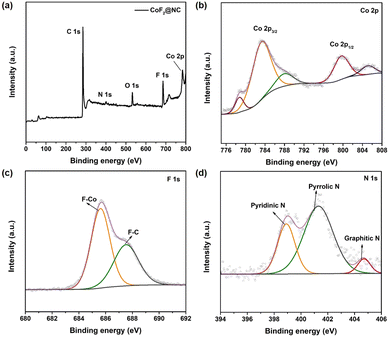 | ||
| Fig. 2 (a) XPS survey spectrum of CoF2@NC. High-resolution XPS spectra of (b) Co 2p, (c) F 1s and (d) N 1s. | ||
Raman characterizations were carried out for further investigations. As shown in Fig. S3a (ESI†), the Raman spectrum of Co@NC or CoF2@NC presents two prominent peaks at 1345 cm−1 for the D band and 1590 cm−1 for the G band, corresponding to the disordered (sp3) carbon and crystalline graphitic (sp2) carbon, respectively.46 In addition, the intensity ratio of the D and G band (ID/IG) is applied to characterize the degree of carbon crystallinity. According to the calculations, the ID/IG values of Co@NC and CoF2@NC are 2.46 and 2.16, respectively. The lower ID/IG ratio of CoF2@NC means rather higher graphitization of the carbon framework, which is beneficial to improve the electrical conductivity and enable rapid charge transfer between Li+ and the CoF2@NC matrix. To analyse the surface functional groups of the CoF2@NC, the Fourier-transform infrared spectroscopy (FTIR) spectrum was recorded, as shown in Fig. S3b (ESI†). The peaks at 3422 cm−1, 1632 cm−1 and 1093 cm−1 are attributed to O–H, C![[double bond, length as m-dash]](https://www.rsc.org/images/entities/char_e001.gif) C and C–O stretching vibrations, respectively.47,48 In particular, the peak located at about 653 cm−1 corresponds to the Co–F bond, indicating that fluorine is successfully introduced into the carbonized ZIF-67 framework.
C and C–O stretching vibrations, respectively.47,48 In particular, the peak located at about 653 cm−1 corresponds to the Co–F bond, indicating that fluorine is successfully introduced into the carbonized ZIF-67 framework.
To further study the pore structure evolution of Co@NC and CoF2@NC, nitrogen adsorption–desorption isotherm measurements were carried out. As can be seen from Fig. S4 (ESI†), both Co@NC and CoF2@NC display type-IV N2 adsorption/desorption isotherms, demonstrating the coexistence of hierarchical pores. The BET surface areas of Co@NC and CoF2@NC were measured to be 314.8 and 156.1 cm−2 g−1, respectively, which are favourable to decrease the local current density and facilitate uniform Li deposition on the substrate. The BET surface area of CoF2@NC is lower than that of Co@NC, which is owing to the formation of large nanoparticles during fluorination. Through the above analyses, it can be concluded that the carbonized product of ZIF-67 could be directly transferred into the CoF2@NC matrix via the facile fluoridation treatment with PTFE as the F source.
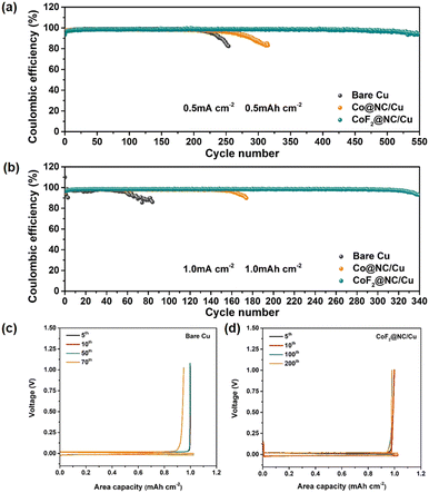
To investigate the effect of CoF2@NC on the Li stripping/plating reversibility, Coulombic efficiency measurements were conducted by assembling Li|Cu cells with CoF2@NC/Cu, Co@NC/Cu and bare Cu foil as the working electrodes and Li foils as the counter electrodes. Before CE cycling, all the Li|Cu cells were firstly cycled at a current density of 0.05 mA cm−2 for constructing stable SEI layers. To explore the Li nucleation barrier on different substrates, nucleation overpotentials that are defined as the voltage differences between the voltage dips and subsequent voltage plateaus in the voltage–capacity profiles are displayed in Fig. S6 (ESI†). Obviously, the nucleation overpotential of the CoF2@NC/Cu substrate was measured as 20.4 mV at a current density of 0.5 mA cm−2, which is smaller than those of Co@NC/Cu (22.3 mV) and bare Cu electrodes (27.6 mV). Such results clearly evidence the improved lithiophilicity of CoF2@NC to reduce the Li nucleation barrier, which is beneficial for the subsequent uniform Li deposition. The CE comparisons of CoF2@NC/Cu, Co@NC/Cu and bare Cu substrates in Fig. 3a exhibit that the initial CE value of the bare Cu current collector is 95.43% at 0.5 mA cm−2 and 0.5 mA h cm−2, which is slightly higher than those of the Co@NC/Cu (91.21%) and CoF2@NC/Cu (93.37%) substrates. The inferior initial CE is possibly attributed to the formation of SEI layers on the Co@NC and CoF2@NC matrixes. However, upon the subsequent cycling, the CoF2@NC/Cu substrate demonstrates a longer cycling lifespan and higher CE value in comparison with those of the Co@NC/Cu and bare Cu current collectors. Specifically, the stripping/plating CEs of the Li|Cu cells based on the Co@NC/Cu and bare Cu current collectors suffer from sharp declines after 200 and 300 cycles, respectively. By contrast, the Li|Cu cell with the CoF2@NC/Cu substrate shows improved electrochemical stability, which remains at a high CE of 96.6% even after 500 cycles. With further cycling at the current density of 1 mA cm−2 under the capacity of 1 mA h cm−2, the CoF2@NC/Cu-based Li|Cu cell still maintains prominent stripping/plating performance with enhanced CE of 98.4% for ∼300 cycles (Fig. 3b). Nevertheless, the Li|Cu cells with Co@NC/Cu and bare Cu current collectors deliver relatively poor electrochemical performance, exhibiting much shorter cycling lifespans of less than 180 and 80 cycles, respectively. The corresponding voltage profiles of Li plating/stripping on CoF2@NC/Cu, Co@NC/Cu and bare Cu at a current density of 1 mA cm−2 for 1 mA h cm−2 are shown in Fig. 3c–e. It can be obviously seen that the Li|Cu cell with the CoF2@NC/Cu electrode exhibits excellent overlap compared to those of the Co@NC/Cu- and bare Cu-based cells, suggestive of the favourable Li stripping/plating reversibility on the CoF2@NC/Cu substrate. Furthermore, when the Li|Cu cells were tested at a higher current density of 2 mA cm−2 under the capacity of 1 mA h cm−2 (Fig. S7, ESI†), the CEs of the bare Cu and Co@NC/Cu substrates suffer from obvious declines only after 80 and 100 cycles, respectively. In contrast, the CE of CoF2@NC/Cu still remains at 95.34% after 150 cycles, much more superior to those of bare Cu and Co@NC/Cu.
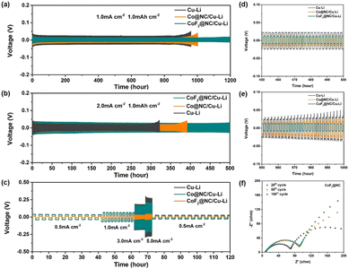
Furthermore, symmetric cells were assembled to evaluate the long-term Li stripping/plating stability of the Li@CoF2@NC/Cu, Li@Co@NC/Cu, and Li@Cu anodes, which were fabricated by depositing 6 mA h cm−2 of Li on the substrates. Fig. 4a displays the galvanostatic voltage profiles of the symmetric cells with various anodes at 1 mA cm−2 and 1 mA h cm−2. It is obvious that the Li@Cu symmetric cell presents the highest voltage polarization among the three cells, which suffers from a sudden increase after 900 h, implying the unstable SEI layer caused by the continuous consumption of electrolyte and Li dendrite growth. As for the Li@Co@NC/Cu-based symmetric cell, a smaller initial overpotential than that of the Li@Cu cell is presented, but just maintaining stability for ∼1000 h, suggesting the formation of Li dendrites and the cracking of the SEI layers. In contrast, the Li@CoF2@NC/Cu symmetric cell displays a slightly lower and more stable voltage hysteresis without evident potential fluctuation for more than 1200 h, demonstrating its long-term cycling lifespan. Moreover, the enlarged voltage profiles between 450 and 500 and 950 and 1000 h indicate that the Li@CoF2@NC/Cu symmetric cell shows lower voltage hysteresis and smoother plateaus than those of the Li@Co@NC/Cu and Li@Cu cells (Fig. 4d and e), suggesting the excellent Li stripping/plating behaviour and transfer kinetics of the Li@CoF2@NC/Cu anode. When the current density was increased to 2 mA cm−2 (Fig. 4b), the Li@CoF2@NC/Cu symmetric cell exhibits more stable long-term cycling performance, and maintains steady cycling for 500 h, proving the formation of an effective SEI layer upon cycling and outstanding suppression of dendritic Li. However, the cells based on the Li@Co@NC/Cu and Li@Cu anodes show stable voltage overpotentials at 380 and 300 h, followed by apparent overpotential increases in the subsequent cycles. Besides, the rate performance was evaluated to further investigate the voltage hysteresis at different current densities (Fig. 4c). As the current density increases from 0.5 to 5 mA cm−2, the Li@CoF2@NC/Cu symmetric cell retains steady and lower voltage hysteresis than the Li@Co@NC/Cu and Li@Cu symmetric cells at each stage, demonstrating the superior reaction kinetics between the interface of the Li@CoF2@NC/Cu anode and electrolyte.
Electrochemical impedance spectroscopy (EIS) measurements were conducted to explore the evolution of the interfacial impedance of different electrodes. Generally, the semicircle at the high-medium frequency regions and sloped line at low frequency areas are related to surface film impedance (Rsf) and the charge transfer resistance (Rct), respectively.49Fig. 4f and Fig. S8 (ESI†) display the Nyquist plots of the symmetric cells after different cycles. The interfacial resistance of the cell based on the Li@Cu anode increased with the charge/discharge cycles before 50 cycles and decreased after 100 cycles, which should be attributed to the formation of a stable electrode interface after the activation process, as well as the deterioration of the SEI layer and the formation of Li dendrites during cycling. As for the symmetric cell based on the Li@Co@NC/Cu electrode, the corresponding resistances increased gradually during the cell operation, which could be ascribed to the accumulation of the SEI layer because of the reaction between the Li metal and organic electrolyte. In the case of the Li@CoF2@NC/Cu based cell, the Nyquist plots presented excellent coincidence between the shape of the semicircle after 100 cycles and the semicircle after 50 cycles, indicating superior cycling stability of the Li@CoF2@NC/Cu electrode.
Fig. S9 (ESI†) displays the morphology evolution during Li plating with capacities from 0.2 to 3 mA h cm−2 on bare Cu, Co@NC/Cu and CoF2@NC/Cu electrodes. Due to the poor Li affinity of Cu foil with Li, an uneven surface with massive Li particles is observed on the bare Cu foil at the beginning of Li plating (0.2 mA h cm−2). After that, lithium ions are constantly attracted and form moss-like protrusions with the Li deposition capacity increasing to 1 mA h cm−2. Finally, the whisker-type Li network is found in Fig. S9c (ESI†) with the capacity growing to 3 mA h cm−2. As for the Co@NC/Cu and CoF2@NC/Cu electrodes, no obvious Li deposition could be found on the coating surface with the capacity of 0.2 mA h cm−2 and 1 mA h cm−2. After further increasing the Li deposition capacity to 3 mA h cm−2, the morphology of deposited lithium on Co@NC and CoF2@NC appears as dense and dendrite-free bulk. This indicates that the CoF2@NC can accommodate a certain amount of Li and the good Li affinity of the skeleton is beneficial to the uniform Li deposition. Furthermore, in order to confirm the role of CoF2@NC coating in controlling the Li plating/stripping process, the surface morphology evolutions of different electrodes were investigated by ex situ SEM observations, where the Li|Cu cells were cycled at 1 mA cm−2 and 1 mA h cm−2 for 10, 50, and 100 cycles, respectively. As displayed in Fig. 5a, the surface of the bare Cu exhibits a rough morphology with filament-like Li dendrites after 10 cycles. After 50 and 100 cycles, excessive Li dendrites are clearly covered on the surface of Cu foil due to the inhomogeneous Li stripping/plating process (Fig. 5b and c). In the case of the Co@NC/Cu current collector, a small amount of dendritic Li is still unevenly distributed, which resulted from the poor lithiophilicity of the Co@NC coating (Fig. 5d and e). As shown in Fig. 5e, the cycled Co@NC electrode shows a broken and uneven surface after 100 cycles. In contrast, the CoF2@NC/Cu electrode displays more uniform and flat Li deposition after 10 cycles (Fig. 5g). More attractively, smooth surface morphologies are still maintained even after 50 or 100 cycles (Fig. 5h and i), proving that the lithiophilic CoF2@NC coating enables a more homogeneous Li stripping/plating process. Moreover, the flat surface has a smaller specific surface area of lithium deposits, which is more conducive to the stability of the battery.50
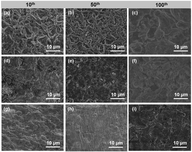 | ||
| Fig. 5 Ex situ SEM images of (a–c) bare Cu, (d–f) Co@NC/Cu, and (g–i) CoF2@NC/Cu electrodes disassembled from Li|Cu cells after 10, 50, and 100 cycles at 1 mA cm−2 and 1 mA h cm−2. | ||
To further investigate the functional mechanism of CoF2@NC in the formation of SEI layers, the surface of the Li@CoF2@NC/Cu anode was further investigated by XPS measurements after 10 cycles and the Li@Cu anode was used as a control sample. As can be seen in Fig. 6a and c, the components on both anodes mainly include C–C/C–H (≈284.8 eV), C–O (≈286.5 eV), C![[double bond, length as m-dash]](https://www.rsc.org/images/entities/char_e001.gif) O (≈288.8 eV), CO3 (≈290 eV) and C–F (≈292.8 eV) in the C 1s spectra,51,52 which originate from the decomposition of the electrolyte. As shown in Fig. 6b and d, the peaks at about 685.0 and 688.5 eV in the F 1s spectrum belong to LiF and C–F, respectively.53,54 Based on the relative peak intensity comparison, it is obvious that the cycled Li@CoF2@NC/Cu electrode possesses more abundant LiF component in the SEI layer, which is responsible for the homogeneous Li deposition process. As illustrated in Fig. 7, brittle SEI layers are usually formed on unmodified bare Cu foil during cycling, resulting in uneven Li deposition and sharp Li dendrites. In contrast, the CoF2@NC matrix can not only decrease the Li nucleation overpotential on the substrate, but also react with Li+ during cycling to generate LiF-enriched SEI layers, so that the CoF2@NC/Cu current collector achieves dendrite-suppressed Li stripping/plating behaviour with high Coulombic efficiency and extended lifespan.
O (≈288.8 eV), CO3 (≈290 eV) and C–F (≈292.8 eV) in the C 1s spectra,51,52 which originate from the decomposition of the electrolyte. As shown in Fig. 6b and d, the peaks at about 685.0 and 688.5 eV in the F 1s spectrum belong to LiF and C–F, respectively.53,54 Based on the relative peak intensity comparison, it is obvious that the cycled Li@CoF2@NC/Cu electrode possesses more abundant LiF component in the SEI layer, which is responsible for the homogeneous Li deposition process. As illustrated in Fig. 7, brittle SEI layers are usually formed on unmodified bare Cu foil during cycling, resulting in uneven Li deposition and sharp Li dendrites. In contrast, the CoF2@NC matrix can not only decrease the Li nucleation overpotential on the substrate, but also react with Li+ during cycling to generate LiF-enriched SEI layers, so that the CoF2@NC/Cu current collector achieves dendrite-suppressed Li stripping/plating behaviour with high Coulombic efficiency and extended lifespan.
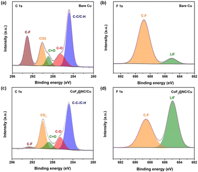 | ||
| Fig. 6 C 1s XPS spectra of (a) bare Cu and (c) CoF2@NC/Cu electrodes after 10 cycles. F 1s XPS spectra of (b) bare Cu and (d) CoF2@NC/Cu electrodes after 10 cycles. | ||
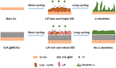 | ||
| Fig. 7 Schematic illustration of the Li stripping/plating cycling on (a) bare Cu and (b) CoF2@NC/Cu current collectors. | ||
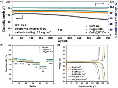
In order to explore the feasibility of the CoF2@NC/Cu current collector in practical applications, commercial LiFePO4 (LFP) was employed as the cathode to match with the Li@CoF2@NC/Cu composite anode, which was obtained by depositing 6 mA h cm−2 of Li on the CoF2@NC/Cu matrix. Fig. 8a presents the long-term cycling stability of LFP full cells with Li@CoF2@NC/Cu, Li@Co@NC/Cu, and Li@Cu composite anodes. The LFP|Li@CoF2@NC/Cu full cell exhibits the most superior initial specific capacity of 150 mA h g−1 in comparison with the LFP|Li@Co@NC/Cu (138 mA h g−1) and LFP|Li@Cu (124 mA h g−1) full cells. In addition, the full cell based on the Li@CoF2@NC/Cu anode demonstrates superb capacity retention of 95.4% with a high CE exceeding 99.9% after 500 cycles, suggesting the homogeneous Li stripping/plating behaviour and high reversibility resulting from the dendrite-suppressed Li deposition and LiF-enriched SEI layer. In contrast, the full cells with Li@Co@NC/Cu and Li@Cu anodes display considerably inferior cycling performance with apparent capacity decline, which is attributed to the formation of dendritic Li and accumulation of dead Li during the Li plating/stripping process. Furthermore, the rate comparisons of full cells under different current densities in Fig. 8b certify the improved rate performance of the LFP|Li@CoF2@NC/Cu cell. The discharge/charge voltage profiles at different cycles shown in Fig. 8c further demonstrate the higher capacity retention in LFP|Li@CoF2@NC/Cu than those in the LFP|Li@Co@NC/Cu and LFP|Li@Cu full cells. Besides, as displayed in Fig. S10 (ESI†), under the harsh conditions of N/P = 4.74 and lean electrolyte at 2C, the discharge capacity of the Li@Cu based full cell drops sharply to less than 80% within 25 cycles. In contrast, the full cell composed of Li@Co@NC/Cu shows a capacity retention below 80% after 55 cycles, while the full cell with the Li@CoF2@NC/Cu anode delivers improved cycling performance with a capacity retention of ∼90% after 80 cycles.
Conclusions
In summary, we have prepared CoF2 decorated N-doped carbon via a convenient fluoridation treatment after the carbonation of ZIF-67 precursor, which was employed as a lithiophilic host for enabling homogeneous Li electrodeposition. Benefitting from the synergy effect of high lithiophilicity provided by the N-doped carbon and CoF2 nanoparticles and the as-generated LiF-enriched SEI layer, lower nucleation overpotential and more uniform Li stripping/plating behaviour were realized on the CoF2@NC decorated Cu current collector. Consequently, the Li|Cu cell with the CoF2@NC/Cu substrate exhibited high reversibility (∼96.6% after 500 cycles) and the Li|Li symmetric cell with the Li@CoF2@NC/Cu anode demonstrated improved cycling stability (1200 h). Moreover, the assembled LiFePO4 full cell with a Li@CoF2@NC/Cu anode delivered excellent rate performance and cycling stability, showing great potential in the practical application of LMBs. Our exploration of a metal fluoride-modified carbon matrix paves a new path for the modification of current collectors and long lifespan Li metal batteries.Conflicts of interest
The authors declare that they have no known competing financial interests or personal relationships that could have appeared to influence the work reported in this paper.Acknowledgements
The authors acknowledge financial support from the National Natural Science Foundation of China (No. 51621002, and 51972112), the Leading Talents in Shanghai in 2018 and the 111 project (B14018).References
- Y. Zhang, T. T. Zuo, J. Popovic, K. Lim, Y. X. Yin, J. Maier and Y. G. Guo, Mater. Today, 2020, 33, 56–74 CrossRef CAS.
- P. B. Zhai, L. X. Liu, X. K. Gu, T. S. Wang and Y. J. Gong, Adv. Energy Mater., 2020, 10, 2001257 CrossRef CAS.
- L. Chen, W. X. Li, L. Z. Fan, C. W. Nan and Q. Zhang, Adv. Funct. Mater., 2019, 29, 1901047 CrossRef.
- D. C. Lin, Y. Y. Liu and Y. Cui, Nat. Nanotechnol., 2017, 12, 194–206 CrossRef CAS PubMed.
- X. B. Cheng, R. Zhang, C. Z. Zhao and Q. Zhang, Chem. Rev., 2017, 117, 10403–10473 CrossRef CAS PubMed.
- J. F. Qian, B. D. Adams, J. M. Zheng, W. Xu, W. A. Henderson, J. Wang, M. E. Bowden, S. C. Xu, J. Z. Hu and J. G. Zhang, Adv. Funct. Mater., 2016, 26, 7094–7102 CrossRef CAS.
- W. Xu, J. L. Wang, F. Ding, X. L. Chen, E. Nasybulin, Y. H. Zhang and J. G. Zhang, Energy Environ. Sci., 2014, 7, 513–537 RSC.
- H. L. Dai, X. X. Gu, J. Dong, C. Wang, C. Lai and S. H. Sun, Nat. Commun., 2020, 11, 643 CrossRef CAS PubMed.
- L. B. Ma, J. Cui, S. S. Yao, X. M. Liu, Y. S. Luo, X. P. Shen and J. K. Kim, Energy Storage Mater., 2020, 27, 522–554 CrossRef.
- Z. A. Ghazi, Z. H. Sun, C. G. Sun, F. L. Qi, B. G. An, F. Li and H. M. Cheng, Small, 2019, 15, e1900687 CrossRef PubMed.
- J. Cai, G. X. Huang, X. P. Jin, C. Wei, J. Y. Mao and Y. S. Li, J. Inorg. Mater., 2022, 37, 1337–1343 CrossRef.
- M. Q. Wang, Z. Peng, W. W. Luo, Q. Zhang, Z. D. Li, Y. Zhu, H. Lin, L. T. Cai, X. Y. Yao, C. Y. Ouyang and D. Y. Wang, Adv. Sci., 2020, 7, 2000237 CrossRef CAS PubMed.
- S. Park, H. J. Jin and Y. S. Yun, Adv. Mater., 2020, 32, e2002193 CrossRef PubMed.
- L. Huang, T. Lu, G. J. Xu, X. H. Zhang, Z. X. Jiang, Z. Q. Zhang, Y. T. Wang, P. X. Han, G. L. Cui and L. Q. Chen, Joule, 2022, 6, 906–922 CrossRef CAS.
- G. Wang, X. H. Xiong, D. Xie, X. X. Fu, X. D. Ma, Y. P. Li, Y. Z. Liu, Z. Lin, C. G. Yang and M. L. Liu, Energy Storage Mater., 2019, 23, 701–706 CrossRef.
- J. Y. Qu, S. M. Wang, F. Wu and C. Z. Zhang, ACS Appl. Mater. Interfaces, 2021, 13, 18283–18293 CrossRef CAS PubMed.
- W. N. Xu, X. B. Liao, W. W. Xu, C. L. Sun, K. N. Zhao, Y. Zhao and C. G. Hu, Nano Energy, 2021, 88, 106237 CrossRef CAS.
- W. Z. Cao, J. Z. Lu, K. Zhou, G. C. Sun, J. Y. Zheng, Z. Geng and H. Li, Nano Energy, 2022, 95, 106983 CrossRef CAS.
- H. J. Wang, L. L. Wu, B. Xue, F. Wang, Z. K. Luo, X. G. Zhang, L. Calvez, P. Fan and B. Fan, ACS Appl. Mater. Interfaces, 2022, 14, 15214–15224 CrossRef CAS PubMed.
- C. Chen, Q. W. Liang, G. Wang, D. D. Liu and X. H. Xiong, Adv. Funct. Mater., 2021, 32, 2107249 CrossRef.
- Y. Wang, W. Q. Zhang, Y. Y. Qi, S. F. Wang, P. Liu, X. Y. Wei, Y. H. Yu, W. W. Sun, X. Z. Zhao and Y. M. Liu, J. Alloys Compd., 2021, 874, 159916 CrossRef CAS.
- N. X. Zhang, T. Zhao, L. Wei, T. Feng, F. Wu and R. J. Chen, J. Power Sources, 2022, 536, 231374 CrossRef CAS.
- Y. Zhao, Q. Li, Z. Liu, L. K. Fan, J. J. Li, Z. P. Ma, X. J. Qin and G. J. Shao, ACS Appl. Mater. Interfaces, 2020, 12, 37967–37976 CrossRef CAS PubMed.
- M. Jia, P. Wen, Z. T. Wang, Y. C. Zhao, Y. M. Liu, J. Lin, M. Chen and X. R. Lin, Adv. Funct. Mater., 2021, 31, 2101736 CrossRef CAS.
- G. M. Hou, X. X. Ma, Q. D. Sun, Q. Ai, X. Y. Xu, L. N. Chen, D. P. Li, J. H. Chen, H. Zhong, Y. Li, Z. B. Xu, P. C. Si, J. K. Feng, L. Zhang, F. Ding and L. J. Ci, ACS Appl. Mater. Interfaces, 2018, 10, 18610–18618 CrossRef CAS PubMed.
- J. W. Li, Y. Y. Li, J. Cheng, Q. Sun, L. N. Dai, X. K. Nie, L. N. Chen, G. F. Han and L. J. Ci, Carbon, 2021, 177, 52–59 CrossRef CAS.
- R. S. Chen, A. M. Nolan, J. Lu, J. Y. Wang, X. Q. Yu, Y. F. Mo, L. Q. Chen, X. J. Huang and H. Li, Joule, 2020, 4, 812–821 CrossRef CAS.
- J. Z. Man, W. L. Liu, H. B. Zhang, K. Liu, Y. F. Cui, J. P. Yin, X. Y. Wang and J. C. Sun, J. Mater. Chem. A, 2021, 9, 13661–13669 RSC.
- Y. Wang, J. Huang, Y. J. Xiao, Z. Y. Peng, K. Yuan, L. C. Tan and Y. W. Chen, Carbon, 2019, 147, 146–153 CrossRef CAS.
- J. Qian, Y. Li, M. H. Zhang, R. Luo, F. J. Wang, Y. S. Ye, Y. Xing, W. L. Li, W. J. Qu, L. L. Wang, L. Li, Y. J. Li, F. Wu and R. J. Chen, Nano Energy, 2019, 60, 866–874 CrossRef CAS.
- Z. X. Li, B. L. Yang, K. Y. Zou, L. J. Kong, M. L. Yue and H. H. Duan, Carbon, 2019, 144, 540–548 CrossRef CAS.
- X. Q. Xu, X. B. Cheng, F. N. Jiang, S. J. Yang, D. S. Ren, P. Shi, H. J. Hsu, H. Yuan, J. Q. Huang, M. Ouyang and Q. Zhang, SusMat, 2022, 2, 435–444 CrossRef CAS.
- F. N. Jiang, S. J. Yang, Z. X. Chen, H. Liu, H. Yuan, L. Liu, J. Q. Huang, X. B. Cheng and Q. Zhang, Particuology, 2023, 79, 10–17 CrossRef CAS.
- Y. X. Yuan, F. Wu, Y. Bai, Y. Li, G. H. Chen, Z. H. Wang and C. Wu, Energy Storage Mater., 2019, 16, 411–418 CrossRef.
- W. S. Jia, Q. J. Wang, J. Y. Yang, C. Fan, L. P. Wang and J. Z. Li, ACS Appl. Mater. Interfaces, 2017, 9, 7068–7074 CrossRef CAS PubMed.
- J. Tan, J. Matz, P. Dong, J. F. Shen and M. X. Ye, Adv. Energy Mater., 2021, 11, 210046 Search PubMed.
- M. F. He, R. Guo, G. M. Hobold, H. N. Gao and B. M. Gallant, Proc. Natl. Acad. Sci. U. S. A., 2020, 117, 73–79 CrossRef CAS PubMed.
- C. Cao, T. P. Pollard, O. Borodin, J. E. Mars, Y. Tsao, M. R. Lukatskaya, R. M. Kasse, M. A. Schroeder, K. Xu, M. F. Toney and H. G. Steinrück, Chem. Mater., 2021, 33, 7315–7336 CrossRef CAS.
- J. Zhang, J. Y. Huang, Y. C. Li, Q. Liu, Z. S. Yu, J. X. Wu, Z. R. Gao, S. Z. Wu, J. Y. Kui and J. X. Song, Polymers, 2019, 11, 1469 CrossRef CAS PubMed.
- M. Xia, C. C. Ge, Q. Z. Yan, H. Y. Guo and L. N. Yue, Appl. Phys. A: Mater. Sci. Process., 2012, 107, 777–782 CrossRef CAS.
- C. G. Pei, H. B. Chen, B. X. Dong, X. Yu and L. G. Feng, J. Power Sources, 2019, 424, 131–137 CrossRef CAS.
- F. X. Wu, V. Srot, S. Q. Chen, M. Y. Zhang, P. A. V. Aken, Y. Wang, J. Maier and Y. Yu, ACS Nano, 2021, 15, 1509–1518 CrossRef CAS PubMed.
- Z. Liu, X. Yu, H. G. Xue and L. G. Feng, J. Mater. Chem. A, 2019, 7, 13242–13248 RSC.
- Y. Ha, B. Fei, X. X. Yan, H. B. Xu, Z. L. Chen, L. X. Shi, M. Fu, W. Xu and R. B. Wu, Adv. Energy Mater., 2020, 10, 2002592 CrossRef CAS.
- X. F. Zhou, L. L. Chen, W. H. Zhang, J. W. Wang, Z. J. Liu, S. F. Zeng, R. Xu, Y. Wu, S. F. Ye, Y. Z. Feng, X. L. Cheng, Z. Q. Peng, X. F. Li and Y. Yu, Nano Lett., 2019, 19, 4965–4973 CrossRef CAS PubMed.
- X. T. Li, H. C. Zhang, C. Liu, J. Y. Qiao and X. M. Zhou, Microporous Mesoporous Mater., 2021, 310, 110650 CrossRef CAS.
- J. L. Yan, G. J. Chen, J. Cao, W. Yang, B. H. Xie and M. B. Yang, New Carbon Mater., 2012, 27, 370–376 CrossRef CAS.
- D. C. Marcano, D. V. Kosynkin, J. M. Berlin, A. Sinitskii, Z. Z. Sun, A. Slesarev, L. B. Alemany, W. Lu and J. M. Tour, ACS Nano, 2010, 4, 4806–4814 CrossRef CAS PubMed.
- G. Y. Jiang, N. Jiang, N. Zheng, X. Chen, J. Y. Mao, G. Y. Ding, Y. H. Li, F. G. Sun and Y. S. Li, Energy Storage Mater., 2019, 23, 181–189 CrossRef.
- F. N. Jiang, S. J. Yang, X. B. Cheng, P. Shi, J. F. Ding, X. Chen, H. Yuan, L. Liu, J. Q. Huang and Q. Zhang, J. Energy Chem., 2022, 72, 158–165 CrossRef CAS.
- J. G. Han, J. B. Lee, A. Cha, T. K. Lee, W. Cho, S. Chae, S. J. Kang, S. K. Kwak, J. Cho, S. Y. Hong and N. S. Choi, Energy Environ. Sci., 2018, 11, 1552–1562 RSC.
- G. Y. Jiang, K. Y. Li, F. Yu, X. L. Li, J. Y. Mao, W. W. Jiang, F. G. Sun, B. Dai and Y. S. Li, Adv. Energy Mater., 2020, 11, 2003496 CrossRef.
- S. H. Jiao, X. D. Ren, R. G. Cao, M. H. Engelhard, Y. Z. Liu, D. H. Hu, D. H. Mei, J. M. Zheng, W. G. Zhao, Q. Y. Li, N. Liu, B. D. Adams, C. Ma, J. Liu, J. G. Zhang and W. Xu, Nat. Energy, 2018, 3, 739–746 CrossRef CAS.
- Z. Jiang, H. J. Guo, Z. Zeng, Z. L. Han, W. Hu, R. Wen and J. Xie, ACS Nano, 2020, 14, 13784–13793 CrossRef CAS PubMed.
Footnote |
| † Electronic supplementary information (ESI) available. See DOI: https://doi.org/10.1039/d3ya00035d |
| This journal is © The Royal Society of Chemistry 2023 |

