Co/Li2S of chemical confinement decorated electrochemically stable Co(OH)F nanoarrays enabling dendrite-free flexible 3D Li anodes†
Liubin
Song
a,
Yixuan
Wang
a,
Huaming
Qian
b,
Mengxin
Bai
b,
Qinchuan
Chen
b,
Minzhi
Xiao
a,
Tingting
Zhao
*a,
Zhongliang
Xiao
a,
Jingjing
Wang
bc and
Xifei
Li
 *bc
*bc
aSchool of Chemistry and Chemical Engineering, Changsha University of Science and Technology, Changsha 410114, China. E-mail: zhaott_468@163.com
bInstitute of Advanced Electrochemical Energy, School of Materials Science and Engineering, Xi'an University of Technology, Xi'an 710048, PR China. E-mail: xfli@xaut.edu.cn
cGuangdong Yuanneng Technologies Co Ltd, Foshan, Guangdong 528223, China
First published on 1st June 2024
Abstract
Lithium (Li) metal is regarded as a promising anode for high-energy-density Li-ion batteries because of its high theoretical specific capacity and low potential. Unfortunately, the safety issues derived from Li dendrite formation have hindered their commercialization. Thus, fabricating a flexible, three-dimensional (3D) composite Li anode is an effective strategy to suppress Li dendrite growth. Lithiophilic nanoarrays are commonly constructed on a 3D skeleton to increase its surface area and lithiophilicity. However, the lithiophilic nanoarrays are unstable due to the conversion reaction during Li plating/stripping. Therefore, designing composite nanoarrays with an electrochemically stable inner core and a lithiophilic outer shell is conducive to providing a large surface area and promoting uniform Li deposition. Herein, CoS2 shell–Co(OH)F core composite nanowire arrays were prepared on carbon cloth (CoS2–Co(OH)F/CC) to fabricate a flexible 3D composite Li anode (Li@CoS2–Co(OH)F/CC), in which the electrochemically stable Co(OH)F core ensures the stability of the nanoarray and the lithiophilic CoS2 shell facilitates uniform Li adsorption. Moreover, the Co/Li2S configuration derived from the lithiation of CoS2 could promote homogeneous Li deposition, in which the lithiophilic Li2S phase and electron-conductive Co phase jointly facilitate uniform Li nucleation and charge transfer. Consequently, the symmetric cells and full cells paired with a LiFePO4 (LFP) cathode based on the flexible Li@CoS2–Co(OH)F/CC anode presented superior cycling stability.
1. Introduction
Lithium-ion (Li-ion) batteries have been widely utilized in energy storage systems. However, the commercial Li-ion batteries' energy density is approximately 250 Wh kg−1, which poses a challenge to meet the emerging power battery system's demands.1,2 The commercially available Li-ion batteries employ a graphite anode with a specific capacity of only 372 mA h g−1, whereas the Li metal anode exhibits a significantly higher specific capacity of 3860 mA h g−1 at a low potential (−3.04 V vs. the standard hydrogen electrode).3,4 Therefore, the utilization of Li metal anodes exhibits promising potential for enhancing the energy density of Li-ion batteries. Nevertheless, safety concerns arising from Li dendrite formation have seriously hindered the progress of Li-metal batteries.5–7In addressing such intractable issues, many strategies have been developed, including electrolyte modification,8,9 artificial solid–electrolyte interface construction,10–12 separator modification13–15 and 3D electrode fabrication.16–18 According to the theory of “Sand's time,” the charge accumulation on some spots causes the local current density to exceed the limiting current density, which induces uncontrollable Li dendrite growth.19,20 Among the strategies, fabricating a 3D Li metal anode can provide a large space to lower local current density and accommodate Li deposition, thereby decreasing the probability of Li dendrite formation.21–23 Therefore, this strategy has great application potential, whereas the commonly used 3D skeletons are mostly lithiophobic, such as Ni foam,24 Cu foam,25 carbon nanotubes,26 and carbon cloth (CC).17,27 Introducing lithiophilic nanoarrays, including nanospheres, nanowires, and nanorods, onto the surface of a 3D skeleton is often performed to provide a larger surface area and physical space as well as to improve their lithiophilicity.28–30 However, most lithiophilic nanoarrays consist of metallic compounds, which undergo a conversion reaction with Li during initial deposition and subsequently collapse in structure. As a result, they are unable to effectively regulate the subsequent Li plating/stripping process.31,32 Therefore, constructing composite nanoarrays with an electrochemically stable inner core and a lithiophilic outer shell on a 3D skeleton is conducive to providing a stable structure and promoting uniform Li deposition.33
Herein, composite shell–core CoS2–Co(OH)F nanowire arrays were constructed on CC (denoted as CoS2–Co(OH)F/CC) to fabricate a flexible 3D composite Li anode (denoted as Li@CoS2–Co(OH)F/CC). The Co(OH)F core is electrochemically stable, which can maintain the structure of the nanoarray and the large space to decrease current density and accommodate Li deposition. The lithiophilic CoS2 shell can facilitate Li adsorption, and it will be transferred into the Co/Li2S configuration after lithiation, in which the lithiophilic Li2S phase could regulate the oriented Li deposition and the electron-conductive Co phase could ensure efficient charge transfer, thereby synergistically promoting homogeneous Li nucleation and deposition. Consequently, the symmetric cells based on the flexible Li@CoS2–Co(OH)F/CC anode achieved superior cycling stability with a low overpotential (13 mV) over 2500 h cycles. When assembled with a LiFePO4 (LFP) cathode, the LFP//Li@CoS2–Co(OH)F/CC full cell delivered outstanding cycling stability (1500 cycles at 1C).
2. Results and discussion
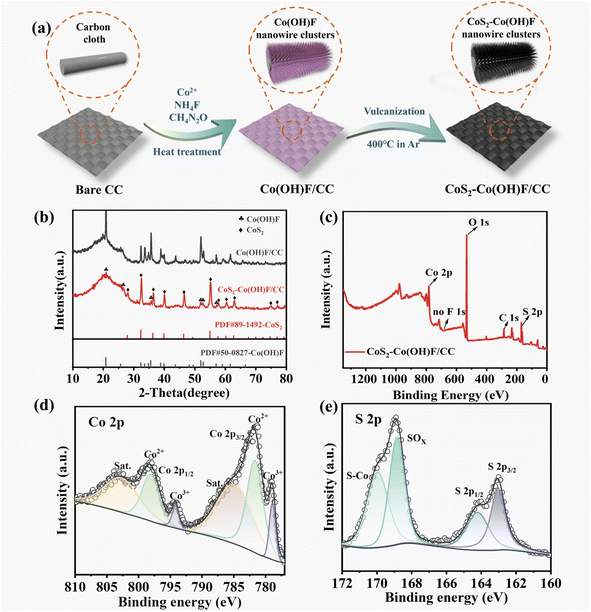
The CoS2–Co(OH)F/CC sample was prepared by a hydrothermal method and vulcanization (Fig. 1a). The XRD results showed that the CoS2–Co(OH)F/CC sample is composed of CoS2 (PDF #89-1492) and Co(OH)F (PDF #50-0827, Fig. 1b). Co and S are detected in the XPS spectra, whereas F is absent (Fig. 1c). Furthermore, the Co 2p spectrum can be fitted into two spin orbit doublets (Co2+ and Co3+) and two satellite peaks (Fig. 1d). Two peaks of 163.1 eV and 164.3 eV are shown in the S 2p spectrograph (Fig. 1e), matching S 2p3/2 and S 2p1/2, respectively.34–36 The Co 2p and S 2p core-level spectra confirm the presence of CoS2. Considering the detection depth of XPS analysis, it indicated that the CoS2 phase is on the outer surface, and Co(OH)F is in the inner core. The abovementioned results confirm the successful preparation of the shell–core CoS2–Co(OH)F composite on CC.The SEM images of the CoS2–Co(OH)F/CC sample showed that its surface is covered with flower-like clusters that are composed of uniform needle-like nanorods (Fig. 2a–c). For comparison, the inadequate concentration of 1.0 mmol Co(NO3)2·6H2O leads to uneven growth of nanowires (Fig. S1a†), while excessive concentration of 2.4 mmol Co(NO3)2·6H2O results in agglomeration and accumulation (Fig. S1b†). An appropriate concentration of 1.7 mmol Co(NO3)2·6H2O leads to uniform and dense nanowire clusters on the surface of the CC with each carbon nanofiber encapsulated by the Co(OH)F clusters. In addition, the SEM images of the pure CC and Co(OH)F precursor clearly illustrate the intricate CC structure formed by interweaved carbon fibers and the nanowire cluster structure of the Co(OH)F precursor indicates that the vulcanization reaction does not alter the overall 3D framework (Fig. S2†). Moreover, the impact of the vulcanization degree on the morphology of the samples was analyzed by regulating the mass ratios of sublimed sulfur to the precursor at 1![[thin space (1/6-em)]](https://www.rsc.org/images/entities/char_2009.gif) :
:![[thin space (1/6-em)]](https://www.rsc.org/images/entities/char_2009.gif) 1, 6
1, 6![[thin space (1/6-em)]](https://www.rsc.org/images/entities/char_2009.gif) :
:![[thin space (1/6-em)]](https://www.rsc.org/images/entities/char_2009.gif) 1, and 30
1, and 30![[thin space (1/6-em)]](https://www.rsc.org/images/entities/char_2009.gif) :
:![[thin space (1/6-em)]](https://www.rsc.org/images/entities/char_2009.gif) 1. The XRD patterns demonstrate a gradual decrease in the peak intensity of the Co(OH)F core and an increase in the presence of the CoS2 shell as the vulcanization degree increases (Fig. S3†), indicating a progressive variation in the Co(OH)F/CoS2 core–shell structure. Furthermore, CoS2–Co(OH)F/CC-6:1 displays a dense layer of CoS2 nanoparticles, indicating the proper vulcanization of the sample. In contrast, CoS2–Co(OH)F/CC (1
1. The XRD patterns demonstrate a gradual decrease in the peak intensity of the Co(OH)F core and an increase in the presence of the CoS2 shell as the vulcanization degree increases (Fig. S3†), indicating a progressive variation in the Co(OH)F/CoS2 core–shell structure. Furthermore, CoS2–Co(OH)F/CC-6:1 displays a dense layer of CoS2 nanoparticles, indicating the proper vulcanization of the sample. In contrast, CoS2–Co(OH)F/CC (1![[thin space (1/6-em)]](https://www.rsc.org/images/entities/char_2009.gif) :
:![[thin space (1/6-em)]](https://www.rsc.org/images/entities/char_2009.gif) 1) and CoS2/CC (30
1) and CoS2/CC (30![[thin space (1/6-em)]](https://www.rsc.org/images/entities/char_2009.gif) :
:![[thin space (1/6-em)]](https://www.rsc.org/images/entities/char_2009.gif) 1) exhibit insufficient and excessive vulcanization, respectively, which demonstrates the exceptional characteristics of the CoS2–CO(OH)F/CC-6
1) exhibit insufficient and excessive vulcanization, respectively, which demonstrates the exceptional characteristics of the CoS2–CO(OH)F/CC-6![[thin space (1/6-em)]](https://www.rsc.org/images/entities/char_2009.gif) :
:![[thin space (1/6-em)]](https://www.rsc.org/images/entities/char_2009.gif) 1 structure (Fig. S4†). The microstructure of the nanorods was further characterized by TEM and selected area electron diffraction (SAED) (Fig. 2d–h), which further confirms the presence of CoS2 on the outer surface of the composite nanorod.34,37 The elemental mapping of Co and S atoms indicated that the CoS2 layer is distributed homogeneously on the surface (Fig. 2d). TEM characterization reveals obvious CoS2 shell and Co(OH)F core structures, as shown in Fig. 2e and f. The lattice fringe in zone I (Fig. 2g) corresponds to the (211) plane of CoS2, while that in zone II corresponds to the (410) plane of Co(OH)F, which further confirms the presence of a shell–core structure of CoS2–Co(OH)F. The width of a single nanorod is approximately 157 nm and sufficient space exists between the nanorods, which is conducive to providing a large surface area and promoting Li deposition.
1 structure (Fig. S4†). The microstructure of the nanorods was further characterized by TEM and selected area electron diffraction (SAED) (Fig. 2d–h), which further confirms the presence of CoS2 on the outer surface of the composite nanorod.34,37 The elemental mapping of Co and S atoms indicated that the CoS2 layer is distributed homogeneously on the surface (Fig. 2d). TEM characterization reveals obvious CoS2 shell and Co(OH)F core structures, as shown in Fig. 2e and f. The lattice fringe in zone I (Fig. 2g) corresponds to the (211) plane of CoS2, while that in zone II corresponds to the (410) plane of Co(OH)F, which further confirms the presence of a shell–core structure of CoS2–Co(OH)F. The width of a single nanorod is approximately 157 nm and sufficient space exists between the nanorods, which is conducive to providing a large surface area and promoting Li deposition.
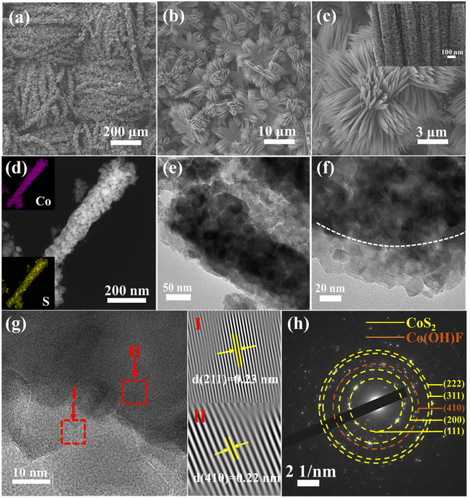 | ||
| Fig. 2 (a–c) SEM images of CoS2–Co(OH)F/CC nanowire clusters at different magnifications. (d) Elemental mapping, (e–g) TEM images, and (h) SAED pattern of the CoS2–Co(OH)F nanorod. | ||
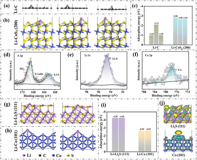
To reveal the effect of the CoS2–Co(OH)F nanorod on the surface lithiophilicity of CC, Li adsorption energy (Ea) was calculated by using the density functional theory (DFT). Ea values on the different sites of C are −1.01, −2.12, and −1.02 eV, whereas Ea values on the different sites of CoS2 are −2.86, −2.68, and −2.68 eV, indicating a stronger interaction between CoS2 and Li than that between C and Li (Fig. 3a–c and S5†). Therefore, the surface lithiophilicity of CC is remarkably improved after being modified by the CoS2–Co(OH)F nanorod, which could facilitate initial Li adsorption or nucleation.
During the initial lithiation process, the discharge curve of the CoS2–Co(OH)F/CC//Li half-cell presented an evident voltage plateau at approximately 1.5 V (Fig. S6†), which indicates the conversion reaction of CoS2 into Li2S and Co.38 Moreover, the XPS analysis of the CoS2–Co(OH)F/CC sample after the conversion reaction shows a peak at 162.2 eV in the XPS S 2p spectrum, a peak at 54.6 eV in the Li 1s spectrum, and a peak at 777.8 eV in the Co 2p spectrum, which indicates the presence of Li2S and Co on the outer surface of the nanorod (Fig. 3d–f).39,40 Furthermore, Ea values on Co and Li2S are −2.69 and −4.28 eV, respectively, which indicates a stronger interaction between Li2S and Li than that between Co and Li (Fig. 3g–i and S7†).41 The charge density difference (Fig. 3j) between Co and Li2S also showed that the charge distribution within Li2S compared with that of Co is more favorable for Li adsorption. Therefore, Li2S within the Co/Li2S configuration could regulate the preferential Li deposition on the Li2S and Co phases to promote a uniform Li deposition. The electron-conductive Co network is conducive to charge transfer.
To reveal the effect of Co/Li2S configuration–derived chemical confinement on regulating Li nucleation and deposition, the SEM images of CoS2–Co(OH)F/CC and pure CC after electrochemical deposition of different capacities of Li were observed. First, after discharging to 1 and 0.01 V, the CoS2–Co(OH)F/CC sample maintains a flower-like structure composed of nanorods (Fig. S8†), which can be attributed to the electrochemically stable Co(OH)F core within the CoS2–Co(OH)F shell–core structure. Additionally, the peak density in the XRD pattern assigned to the Co(OH)F core in the CoS2/CC-30![[thin space (1/6-em)]](https://www.rsc.org/images/entities/char_2009.gif) :
:![[thin space (1/6-em)]](https://www.rsc.org/images/entities/char_2009.gif) 1 sample diminished with increasing degree of vulcanization, showing vulnerable structure stability after lithiation (Fig. S9†) and further validating the stable shell–core structure of CoS2–Co(OH)F/CC (6
1 sample diminished with increasing degree of vulcanization, showing vulnerable structure stability after lithiation (Fig. S9†) and further validating the stable shell–core structure of CoS2–Co(OH)F/CC (6![[thin space (1/6-em)]](https://www.rsc.org/images/entities/char_2009.gif) :
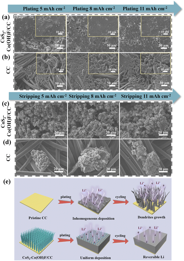
:![[thin space (1/6-em)]](https://www.rsc.org/images/entities/char_2009.gif) 1). After depositing Li with a capacity of 2 mA h cm−2, the CoS2–Co(OH)F/CC sample presented a flower-like structure with Li deposits surrounding the nanowire clusters and filling in the space between nanorods (Fig. S10†). With the increase in the capacity of deposited Li to 5, 8, and 11 mA h cm−2, the Li metal gradually fills in the gaps between the flower-like structure and covers the surface homogenously (Fig. 4a). Conversely, disordered mossy Li was formed on the surface of CC because of its lithiophobic properties, leading to non-uniform Li deposition (Fig. 4b). Hence, the Co/Li2S-modified Co(OH)F nanoarrays could not only accommodate Li and but also facilitate rapid charge transfer, thus promoting the Li plating process. The structure stability of the CoS2–Co(OH)F/CC framework during Li plating/stripping is further explored. The SEM images of the CoS2–Co(OH)F/CC framework after plating 5, 8 and 11 mA h cm−2 Li and stripping 5, 8 and 11 mA h cm−2 Li showed that the decorated-Co(OH)F nanoarray ensures reversible Li plating/stripping and maintains stable structure integrity (Fig. 4c). In contrast, mossy Li deposits still exist on the CC surface because of the formation of “dead Li” (Fig. 4d). After 50 cycles of Li plating/stripping (5 mA h cm−2), the CoS2–Co(OH)F/CC sample maintains a well-preserved flower-like structure, which greatly contributes to prolonged cycling stability (Fig. S11†). This finding indicated that the Co/Li2S configuration-decorated electrochemically stable Co(OH)F nanoarray could effectively regulate the homogeneous Li deposition (Fig. 4e), in which the Co(OH)F nanoarray provides a “physical space” to accommodate Li and the Co/Li2S-derived “chemical confinement” promotes Li adsorption and uniform Li distribution.27,42
1). After depositing Li with a capacity of 2 mA h cm−2, the CoS2–Co(OH)F/CC sample presented a flower-like structure with Li deposits surrounding the nanowire clusters and filling in the space between nanorods (Fig. S10†). With the increase in the capacity of deposited Li to 5, 8, and 11 mA h cm−2, the Li metal gradually fills in the gaps between the flower-like structure and covers the surface homogenously (Fig. 4a). Conversely, disordered mossy Li was formed on the surface of CC because of its lithiophobic properties, leading to non-uniform Li deposition (Fig. 4b). Hence, the Co/Li2S-modified Co(OH)F nanoarrays could not only accommodate Li and but also facilitate rapid charge transfer, thus promoting the Li plating process. The structure stability of the CoS2–Co(OH)F/CC framework during Li plating/stripping is further explored. The SEM images of the CoS2–Co(OH)F/CC framework after plating 5, 8 and 11 mA h cm−2 Li and stripping 5, 8 and 11 mA h cm−2 Li showed that the decorated-Co(OH)F nanoarray ensures reversible Li plating/stripping and maintains stable structure integrity (Fig. 4c). In contrast, mossy Li deposits still exist on the CC surface because of the formation of “dead Li” (Fig. 4d). After 50 cycles of Li plating/stripping (5 mA h cm−2), the CoS2–Co(OH)F/CC sample maintains a well-preserved flower-like structure, which greatly contributes to prolonged cycling stability (Fig. S11†). This finding indicated that the Co/Li2S configuration-decorated electrochemically stable Co(OH)F nanoarray could effectively regulate the homogeneous Li deposition (Fig. 4e), in which the Co(OH)F nanoarray provides a “physical space” to accommodate Li and the Co/Li2S-derived “chemical confinement” promotes Li adsorption and uniform Li distribution.27,42
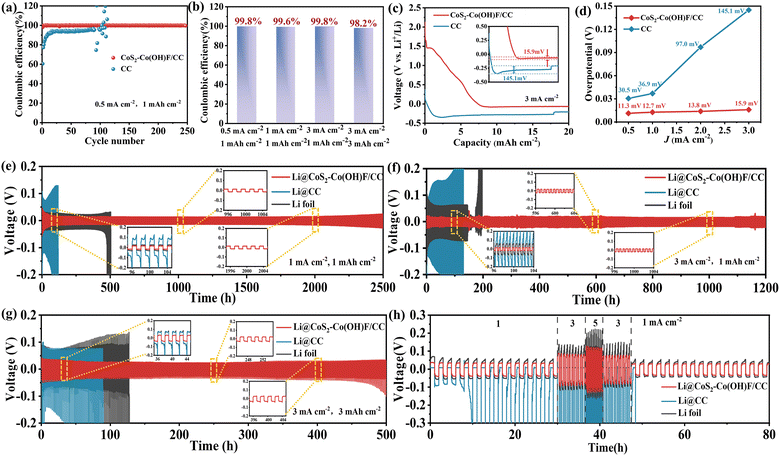
To assess the electrochemical characteristics of the CoS2–Co(OH)F/CC sample, coulombic efficiency (CE) and nucleation overpotential based on the half-cells were tested. As shown in Fig. 5a, at 0.5 mA cm−2 current density and 1 mA h cm−2 capacity, the CoS2–Co(OH)F/CC//Li half-cell exhibits a consistent operational stability for 250 cycles with an average CE exceeding 99%. When increasing the current density and capacity to 1 mA cm−2 and 1 mA h cm−2, 3 mA cm−2 and 1 mA h cm−2, and 3 mA cm−2 and 3 mA h cm−2, the CEs of half-cells remain over 99% (Fig. 5b and S12†). By contrast, the CEs of the CC//Li half-cell are markedly lower than that of CoS2–Co(OH)F/CC, with inferior cycling stability. This impressive achievement can be credited to the Co/Li2S-derived “chemical confinement” in facilitating Li plating and stripping as well as the stable Co(OH)F nanoarrays in ensuring structural stability. In addition, the overpotentials of the CoS2–Co(OH)F/CC and CC samples at different current densities were investigated (Fig. 5c and S13†). The overpotentials of CoS2–Co(OH)F/CC are lower than that of CC at all tested current densities (Fig. 5d), which can be attributed to the effect of the lithiophilic and electron-conductive Co/Li2S configuration in promoting Li nucleation.
The assembled symmetric cells were utilized to explore the cycling stability and interface stability of the electrodes. The composite Li metal anode is obtained through the electrodeposition method. In contrast to the Li infusion method,43 the electrodeposition method allows for precise control over the amount of deposited Li and ensures a uniform morphology, as shown in Fig. S14.† As shown in Fig. 5e, the Li@CoS2–Co(OH)F/CC-based symmetric cells can operate stably for 2500 h with an overpotential of approximately 13 mV (1 mA cm−2, 1 mA h cm−2). In contrast, Li foil symmetric cells presented a large overpotential (25 mV) and poor cycle performance (500 h) under the same conditions. The Li@CC symmetric cells show even worse performance with overpotential increasing from 78.9 to 128 mV, indicating highly unstable Li plating/stripping behavior. During the initial cycle, the symmetric cells based on Li@CoS2–Co(OH)F/CC exhibited a higher overpotential compared to symmetric cells based on Li foil, which illustrates the longer formation period of the SEI film on the surface of Li@CoS2–Co(OH)F/CC than on that of Li. This is because pure Li metal is more active and prone to react with electrolyte and form the SEI film,6 while the Co/Li2S derived composite Li metal is more stable. Furthermore, the Li@CoS2–Co(OH)F/CC symmetric cells still exhibited a prolonged cycle life of 1200 h and maintained an overpotential of 16 mV at 3 mA cm−2/1 mA h cm−2 (Fig. 5f). However, the Li@CC and Li foil symmetric cells showed voltage fluctuations after 105 and 166 h, respectively. Moreover, the Li@CoS2–Co(OH)F/CC-based cell still exhibited satisfactory cycling stability with a small overpotential for 500 h when the capacity further increases to 3 mA cm−2/3 mA h cm−2 (Fig. 5g). The rate capability of Li foil, Li/CC, and Li@CoS2–Co(OH)F/CC-based symmetric cells was also investigated (Fig. 5h). The Li@CoS2–Co(OH)F/CC-based symmetric cell presented exceptional reversibility with a lower overpotential compared with the other two symmetric cells.
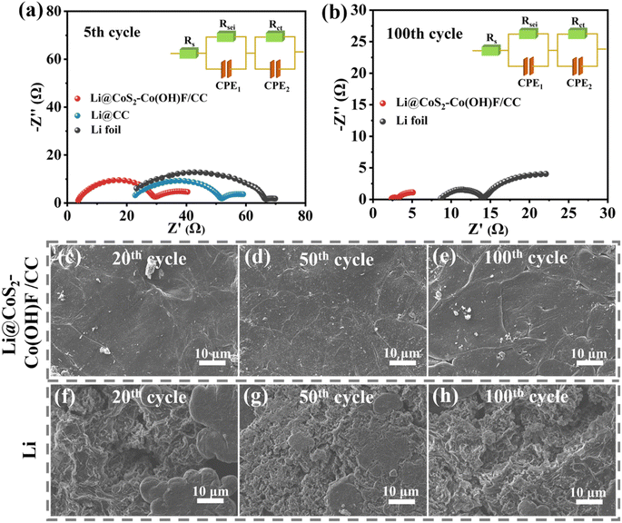
To reveal the cause of the remarkable cycling performance and rate capability of the Li@CoS2–Co(OH)F/CC-based cells, the Nyquist plot of the EIS spectra of Li foil, Li@CC, and Li@CoS2–Co(OH)F/CC-based symmetric cells at the 5th and 100th cycles was captured (Fig. 6a and b). At the 5th cycle, the charge transfer resistance (Rct) of Li foil, Li@CC, and Li@CoS2–Co(OH)F/CC symmetric cells is 44.78 Ω, 31.4 Ω, and 26.1 Ω, respectively. At the 100th cycle, the Rct of Li foil and Li@CoS2–Co(OH)F/CC symmetric cells is 5.5 Ω and 1.1 Ω, respectively (the Li@CC symmetric cells failed before the 100th cycle). The smaller Rct of the Li@CoS2–Co(OH)F/CC-based cell indicated faster Li+ transport and a more stable electrolyte/electrode interface. To reveal the relationship between microstructural stability and long-term cycling stability, the surface morphology of Li@CoS2–Co(OH)F/CC and Li foil-based symmetric cells after the 20th, 50th, and 100th cycles was detected (Fig. 6c–h). The Li@CoS2–Co(OH)F/CC electrode maintains a homogeneous and integral surface covered by Li metal (Fig. 6c–e). However, “dead Li” appeared on the surface of the Li foil even after 20 cycles, and severe cracks occurred after 100 cycles (Fig. 6f–h). Therefore, the Li@CoS2–Co(OH)F/CC anode could maintain remarkable structure stability and effectively suppress Li dendrite formation during repeated Li plating/stripping.
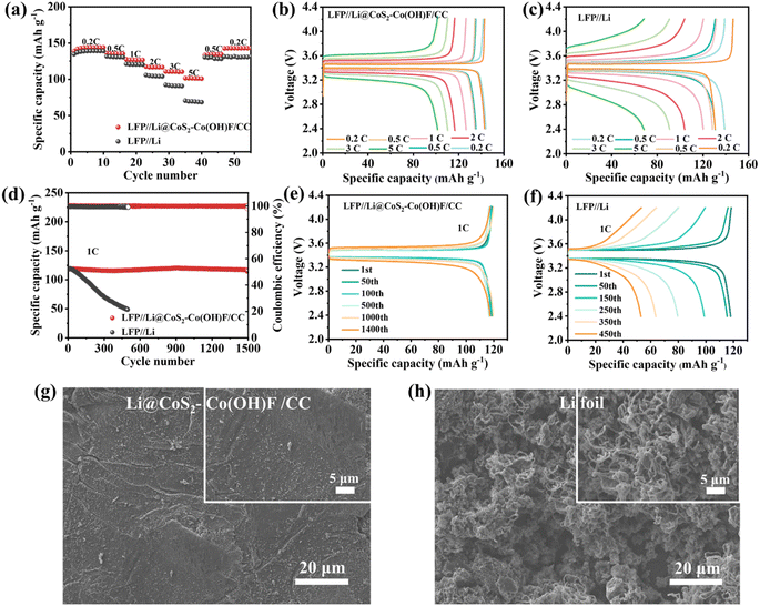
To confirm the potential application of the Li@CoS2–Co(OH)F/CC anode in full cells, the full cells with LFP as the cathode and Li foil and Li@CoS2–Co(OH)F/CC as the anode were assembled (denoted as LFP//Li and LFP//Li@CoS2–Co(OH)F/CC full cells). The discharge capacities of LFP//Li@CoS2–Co(OH)F/CC full cells are 143.8, 135.5, 126.8, 117.4, 110.5 and 101.5 mA h g−1 at 0.2, 0.5, 1, 2, 3, and 5C, respectively (Fig. 7a), which are significantly higher than those of LFP//Li full cells. The charge–discharge profiles of LFP//Li@CoS2–Co(OH)F/CC and LFP//Li full cells at different rates are shown in Fig. 7b and c. The LFP//Li@CoS2–Co(OH)F/CC cell presented a more stable charge–discharge platform and lower voltage polarization than those of the LFP//Li cell. In addition, the cycling performance of the full cells was tested at 1C (Fig. 7d). The LFP//Li@CoS2–Co(OH)F/CC cell demonstrated excellent cycling stability for 1500 cycles at 1C with a discharge capacity of 119.3 mA h g−1 compared with the LFP//Li full cell. Meanwhile, the Li@CoS2–Co(OH)F/CC cell exhibited a more stable charge–discharge platform and lower voltage polarization than the LFP//Li full cell at different cycles (Fig. 7e). However, the discharge capacity of the LFP//Li full cell gradually decreased from the initial cycle because of the presence of Li dendrites. Moreover, the surface morphology of the anode in LFP//Li@CoS2–Co(OH)F/CC and LFP//Li full cells was observed by SEM. As shown in Fig. 7g and S15a, b,† the Li@CoS2–Co(OH)F/CC electrode still maintains a flat and uniform Li coating without any unwanted separation or smashing after 200 and 300 cycles. By contrast, unfavorable phenomena such as volume cracks and Li dendrites are observed in the Li foil of LFP//Li full cells (Fig. 7h and S15c, d†). The good cycling stability and rate performance of Li@CoS2–Co(OH)F/CC-based symmetric cells and full cells are attributed to the Li2S/Co configuration-decorated Co(OH)F nanoarray in stabilizing Li plating and stripping.
3. Conclusion
A highly stable lithiophilic and electron-conductive CoS2–Co(OH)F shell–core nanoarray was successfully prepared on the CC skeleton to fabricate a flexible 3D Li metal anode. The electrochemically stable Co(OH)F core within the nanoarrays ensures structural stability during repeated Li plating/stripping, thereby accommodating Li deposition via the large area space between the nanoarrays. Meanwhile, the Co/Li2S configuration formed on the outer surface of the nanoarrays could not only regulate the preferential Li plating on lithiophilic Li2S sites and then Co sites but also ensure the rapid charge transfer. This derived chemical confinement synergistically promotes further homogeneous Li plating. Based on these advantages, the as-prepared Li@CoS2–Co(OH)F/CC-based symmetric cells presented exceptional cycling stability with a prolonged lifespan of 2500 h and an overpotential of only 13 mV. Furthermore, the LFP//Li@CoS2–Co(OH)F/CC full cells exhibited a stable cycling stability for 1500 cycles at 1C and superior rate capability. Therefore, the flexible 3D Li@CoS2–Co(OH)F/CC anode could stabilize the Li plating/stripping via the functional Co/Li2S configuration-modified Co(OH)F nanoarrays.4. Experimental section
4.1 Experimental materials
Cobalt nitrate hexahydrate (Co(NO3)2·6H2O), urea (CH4N2O) and ammonium fluoride (NH4F) were acquired from Sinopharm Chemical Reagent Co., Ltd. Sublimed sulfur (S) purchased from Tianjin Yongsheng Fine Chemical Co., Ltd. The mentioned reagents are of analytical quality and can be used without further purification. CC with a thickness of 360 μm was purchased from CeTech Co., Ltd.4.2 Preparation of the flexible Li@CoS2–Co(OH)F/CC anode
![[thin space (1/6-em)]](https://www.rsc.org/images/entities/char_2009.gif) :
:![[thin space (1/6-em)]](https://www.rsc.org/images/entities/char_2009.gif) 1, with the sublimed sulfur upstream and the Co(OH)F/CC sample downstream. After annealing in an Ar environment at 400 °C for 1 h with a ramp rate of 5 °C min−1 and cooling down, the CoS2–Co(OH)F/CC sample was obtained.
1, with the sublimed sulfur upstream and the Co(OH)F/CC sample downstream. After annealing in an Ar environment at 400 °C for 1 h with a ramp rate of 5 °C min−1 and cooling down, the CoS2–Co(OH)F/CC sample was obtained.
4.3 Material characterization
The materials were subjected to X-ray diffraction (XRD) analysis using a Bruker D8 Advance instrument, with Cu-Kα radiation (λ = 0.15418 nm) at 40 kV and 40 mA. X-ray photoelectron spectroscopy (XPS) was performed on an Escalab 250xi device manufactured by Thermo Fisher Scientific. Scanning electron microscopy (SEM) examination was conducted using a GeminiSEM 500 instrument. Transmission electron microscopy (TEM) images were captured utilizing a JEM 2100 PLUS microscope. To acquire the XPS data of Li2S and Co after the lithiation of CoS2, the battery was disassembled within a glove box filled with Ar gas (with O2 levels below 0.1 ppm and H2O levels below 0.1 ppm). The target electrode was rinsed with glycol dimethyl ether and dried in the glove box. Then the electrode was transferred to the cavity of the XPS instrument using a transfer bunker under vacuum to prevent oxidation.444.4 Electrochemical measurements
The electrochemical performance was evaluated by conducting tests on CR2032 coin cells that were assembled in the glove box. In the half-cell configuration, a working electrode of the CoS2–Co(OH)F@CC sample with a 12 mm diameter was employed, while a counter electrode consisting of Li foil with a 14 mm diameter was utilized. Celgard 2300 was used as the separator and 1.0 M LiTFSI dissolved in 1,3-dioxolane/1,2-dimethoxyethane (DOL/DME, 1![[thin space (1/6-em)]](https://www.rsc.org/images/entities/char_2009.gif) :
:![[thin space (1/6-em)]](https://www.rsc.org/images/entities/char_2009.gif) 1, v/v) with 2 wt% LiNO3 was used as the electrolyte. The electrolyte volume in each cell was regulated to 60 μL. When testing the CE, the cell was charged to 1 V at a small current of 0.1 mA cm−2 and cycled 5 cycles to form a stable solid electrolyte interface. The electrochemical impedance spectroscopy (EIS) test was conducted using an electrochemical workstation within the frequency range of 100 kHz to 10 mHz. The full cells were constructed using the Li@CoS2–Co(OH)F/CC anode and LiFePO4 (LFP) cathode with an active mass loading of ∼2 mg cm−2. LFP powder, Super P and polyvinylidene fluoride (8
1, v/v) with 2 wt% LiNO3 was used as the electrolyte. The electrolyte volume in each cell was regulated to 60 μL. When testing the CE, the cell was charged to 1 V at a small current of 0.1 mA cm−2 and cycled 5 cycles to form a stable solid electrolyte interface. The electrochemical impedance spectroscopy (EIS) test was conducted using an electrochemical workstation within the frequency range of 100 kHz to 10 mHz. The full cells were constructed using the Li@CoS2–Co(OH)F/CC anode and LiFePO4 (LFP) cathode with an active mass loading of ∼2 mg cm−2. LFP powder, Super P and polyvinylidene fluoride (8![[thin space (1/6-em)]](https://www.rsc.org/images/entities/char_2009.gif) :
:![[thin space (1/6-em)]](https://www.rsc.org/images/entities/char_2009.gif) 1
1![[thin space (1/6-em)]](https://www.rsc.org/images/entities/char_2009.gif) :
:![[thin space (1/6-em)]](https://www.rsc.org/images/entities/char_2009.gif) 1 wt%) were dissolved in N-methylpyrrolidone (NMP) solvent, and the LFP cathode was prepared by a blade-casting method on Cu foil. The concentration of the electrolyte used was 1 M LiPF6 in EC/DEC (1
1 wt%) were dissolved in N-methylpyrrolidone (NMP) solvent, and the LFP cathode was prepared by a blade-casting method on Cu foil. The concentration of the electrolyte used was 1 M LiPF6 in EC/DEC (1![[thin space (1/6-em)]](https://www.rsc.org/images/entities/char_2009.gif) :
:![[thin space (1/6-em)]](https://www.rsc.org/images/entities/char_2009.gif) 1, v/v), with a controlled dosage of 80 μL for each cell. The voltage range for the full cells was maintained at 2.4∼4.2 V. The galvanostatic charge–discharge tests were conducted using a Neware battery test system (CT-4008T, Shenzhen, China).
1, v/v), with a controlled dosage of 80 μL for each cell. The voltage range for the full cells was maintained at 2.4∼4.2 V. The galvanostatic charge–discharge tests were conducted using a Neware battery test system (CT-4008T, Shenzhen, China).
4.5 Theoretical calculations
The GGA-PBE functional was utilized to depict the electron exchange and correlation.45–47 The wave functions were expanded using the DNP-4.4 file, which represents a localized basis set incorporating a polarization d-function.48,49 The spin unrestricted was used in all the calculations because the four models are open-shell systems.47,50 The effective core potentials (ECP) were employed to treat the core electrons of the metal atoms,51–53 while a uniform orbital cutoff of 5.0 Å was applied for all atoms. For the purpose of geometry optimization, the thresholds for achieving convergence were defined as 2 × 10⁻⁵ Ha for energy, 4 × 10⁻³ Ha Å−1 for maximum force, and 5 × 10⁻³ Å for maximum displacement. Additionally, a SCF convergence criterion of 1.0 × 10⁻⁵ Ha was set to ensure accurate determination of electronic energy. The calculation of adsorption energy (Eads) is performed using the equations provided below:46| Eads = (Etotal − Esub − ELi) |
Author contributions
Liubin Song: investigation, methodology, writing − review & editing. Yixuan Wang: investigation, methodology, data curation, writing – original draft. Huaming Qian: data curation, investigation, writing – original draft, writing – review & editing. Mengxin Bai: data curation, methodology, visualization, writing − review & editing. Qinchuan Chen: data curation, validation, writing – review & editing. Minzhi Xiao: data curation, methodology, writing – review & editing. Zhongliang Xiao: writing – original draft, writing – review & editing. Tingting Zhao: visualization, writing – original draft, writing – review & editing. Jingjing Wang: validation, writing – original draft, writing – review & editing. Xifei Li: conceptualization, formal analysis, funding acquisition, project administration, resources, supervision, writing – original draft, writing – review & editing.Conflicts of interest
The authors declare that they have no known competing financial interests or personal relationships that could have appeared to influence the work reported in this paper.Acknowledgements
This work was financially supported by the National Natural Science Foundation of China (21501015), Hunan Provincial Natural Science Foundation of China (2022JJ30604), Hunan Provincial Key Laboratory of Materials Protection for Electric Power and Transportation (2022CL01) and Foshan Science and Technology Innovation Team Project (1920001004098).References
- J. Wang, L. Wang, H. Xu, L. Sheng and X. He, Green Energy Environ., 2024, 9, 454–472 CrossRef CAS.
- J.-F. Ding, Y.-T. Zhang, R. Xu, R. Zhang, Y. Xiao, S. Zhang, C.-X. Bi, C. Tang, R. Xiang, H. S. Park, Q. Zhang and J.-Q. Huang, Green Energy Environ., 2023, 8, 1509–1530 CrossRef CAS.
- L. Wang, P. Gao, C. Li and H. Li, Nano Res., 2023, 16, 8053–8054 CrossRef CAS.
- M. Zhu, X. Zhao, R. Yan and J. Zhang, Curr. Opin. Solid State Mater. Sci., 2023, 27, 101079 CrossRef CAS.
- S. Qian, H. Chen, M. Zheng, Y. Zhu, C. Xing, Y. Tian, P. Yang, Z. Wu and S. Zhang, Energy Storage Mater., 2023, 57, 229–248 CrossRef.
- W. Tang, J. Ma, X. Zhang, Y. Li, S. Meng, Y. Zhang, H. Dong, R. Liu, R. Gao and M. Feng, Energy Storage Mater., 2024, 64, 103084 CrossRef.
- H. Yuan, X. Ding, T. Liu, J. Nai, Y. Wang, Y. Liu, C. Liu and X. Tao, Mater. Today, 2022, 53, 173–196 CrossRef CAS.
- O. B. Chae and B. L. Lucht, Adv. Energy Mater., 2023, 13, 2203791 CrossRef CAS.
- H. Chen, Y.-X. Xie, S.-S. Liu, H. Peng, W.-C. Zheng, P. Dai, Y.-X. Huang, M. Sun, M. Lin, L. Huang and S.-G. Sun, ACS Appl. Mater. Interfaces, 2023, 15, 45834–45843 CrossRef CAS PubMed.
- C. Zhang, Y. Yang, Y. Sun, L. Duan, Z. Mei, Q. An, Q. Jing, G. Zhao and H. Guo, Sci. China Mater., 2023, 66, 2591–2600 CrossRef CAS.
- X. Ding, Y. Xin, Y. Wang, M. Wang, T. Song and H. Gao, ACS Sustain. Chem. Eng., 2023, 11, 6879–6889 CrossRef CAS.
- C. Liu, Z. Yuan, K. Chen, Y. Jiang, M. Yue, K. Dong, Y. Liu, Y. Guo and Y. Wang, ACS Appl. Mater. Interfaces, 2023, 15, 56356–56364 CrossRef CAS PubMed.
- C. Wang, Z. Hao, Y. Hu, Y. Wu, J. Liu, Y. Jin, H. Wang and Q. Zhang, J. Mater. Chem. A, 2023, 11, 8131–8140 RSC.
- C. Zu, J. Li, B. Cai, J. Qiu, Y. Zhao, Q. Yang, H. Li and H. Yu, J. Power Sources, 2023, 555, 232336 CrossRef CAS.
- T. Naren, R. Jiang, P. Qing, S. Huang, C. Ling, J. Lin, W. Wei, X. Ji, Y. Chen, Q. Zhang, G.-C. Kuang and L. Chen, ACS Nano, 2023, 17, 20315–20324 CrossRef CAS PubMed.
- X. Cui, J. Yang, Z. Xu, Q. Liu, Y. Nuli and J. Wang, Nano Energy, 2022, 95, 107013 CrossRef CAS.
- F. Cheng, X. Yang, O. Ka, L. Wen, X. Wang and W. Lu, J. Mater. Chem. A, 2023, 11, 4205–4219 RSC.
- C. Wei, Z. Yao, J. Ruan, Z. Song, A. Zhou, Y. Song, D. Wang, J. Jiang, X. Wang and J. Li, Chin. Chem. Lett., 2024, 35, 109330 CrossRef CAS.
- S. Xia, C. Yang, Z. Jiang, W. Fan, T. Yuan, Y. Pang, H. Sun, T. Chen, X. Li and S. Zheng, Adv. Compos. Hybrid Mater., 2023, 6, 198 CrossRef CAS.
- W. Zhang, J. Wang, H. Zhang, Q. Dong, S. Zhang, B. Sun, Z. Chen, H. Guo, X. Han, Y. Deng and W. Hu, Small Struct., 2024, 5, 2300358 CrossRef CAS.
- X. He, K. Zhang, Z. Zhu, Z. Tong and X. Liang, Chem. Soc. Rev., 2024, 53, 9–24 RSC.
- H. Liang, L. Wang, L. Sheng, H. Xu, Y. Song and X. He, Electrochem. Energy Rev., 2022, 5, 23 CrossRef CAS.
- Y. Fang, S. L. Zhang, Z. P. Wu, D. Luan and X. W. D. Lou, Sci. Adv., 2021, 7, eabg3626 CrossRef CAS PubMed.
- K. Tang, J. Xiao, M. Long, J. Chen, H. Gao and H. Liu, Sustainable Mater. Technol., 2022, 32, e00408 CrossRef CAS.
- M. Sun, K. Huang, X. Lv, G. Ai, F. Gao, C. Lai, T. Zhang and W. Mao, ACS Appl. Mater. Interfaces, 2023, 15, 38956–38964 CrossRef CAS PubMed.
- Y. Yang, E. Hu, Y. Zhu, W. Cao, J. Zhang, Z. Mao, X. Gao and Z. Chen, Chem. Eng. J., 2023, 477, 146879 CrossRef CAS.
- H. Qian, X. Li, Q. Chen, W. Liu, Z. Zhao, Z. Ma, Y. Cao, J. Wang, W. Li, K. Xu, K. Zhang, W. Yan, J. Zhang and X. Li, Adv. Funct. Mater., 2023, 34, 2310143 CrossRef.
- S. Zhang, S. Xiao, D. Li, J. Liao, F. Ji, H. Liu and L. Ci, Energy Storage Mater., 2022, 48, 172–190 CrossRef.
- H. Wang, Y. Liu, Y. Li and Y. Cui, Electrochem. Energy Rev., 2019, 2, 509–517 CrossRef CAS.
- Y. Fang, Y. Zeng, Q. Jin, X. F. Lu, D. Luan, X. Zhang and X. W. Lou, Angew. Chem., Int. Ed., 2021, 60, 8515–8520 CrossRef CAS PubMed.
- X. Liu, K. Long, P. Qing, S. Huang, P. Xiao, C. Ling, Z. Wu and L. Chen, Sci. China Mater., 2023, 66, 4349–4356 CrossRef CAS.
- G.-D. Yang, B. Li, Y.-H. Song, L. Ding, S.-G. Gong, X.-L. Wu, J.-P. Zhang, Y.-F. Li and H.-Z. Sun, Electrochim. Acta, 2022, 430, 141035 CrossRef CAS.
- Q. Wang, T. Lu, Y. Xiao, J. Wu, L. Guan, L. Hou, H. Du, H. Wei, X. Liu, C. Yang, Y. Wei, H. Zhou and Y. Yu, Electrochem. Energy Rev., 2023, 6, 22 CrossRef CAS.
- X. Wang, X. Zhong, Z. Zha, G. He, Z. Miao, H. Lei, Q. Luo, R. Zhang, Z. Liu and L. Cheng, Appl. Mater. Today, 2020, 18, 100464 CrossRef.
- Q. Li, Y. Zhao, H. Liu, P. Xu, L. Yang, K. Pei, Q. Zeng, Y. Feng, P. Wang and R. Che, ACS Nano, 2019, 13, 11921–11934 CrossRef CAS PubMed.
- G. Cao, X. Li, R. Duan, K. Xu, K. Zhang, L. Chen, Q. Jiang, J. Li, J. Wang, M. Li, N. Wang, J. Wang, Y. Xi, C. Xie and W. Li, Nano Energy, 2023, 116, 108755 CrossRef CAS.
- C. Guan, X. Liu, A. M. Elshahawy, H. Zhang, H. Wu, S. J. Pennycook and J. Wang, Nanoscale Horiz., 2017, 2, 342–348 RSC.
- T. Zhang, M. Wu, H. Gu, H. Yu, M. Zhou, X. Guo, Y. Liu, X. Zheng, Q. Kong and J. Zhang, J. Energy Storage, 2023, 73, 108981 CrossRef.
- R. Zhang, B. Chen, C. Shi, J. Sha, L. Ma, E. Liu and N. Zhao, Small, 2023, 19, 2208095 CrossRef CAS PubMed.
- G. Cao, X. Li, L. Chen, R. Duan, J. Li, Q. Jiang, J. Wang, M. Li, M. Li, J. Wang, Y. Xi, W. Li and J. Peng, Small, 2024, 2311174 CrossRef PubMed.
- J. Pan, J. Li, H. Dong, Y. Fang, K. Shi and Q. Liu, Chem. Eng. J., 2022, 447, 137401 CrossRef CAS.
- S. Ye, X. Chen, R. Zhang, Y. Jiang, F. Huang, H. Huang, Y. Yao, S. Jiao, X. Chen, Q. Zhang and Y. Yu, Nano-Micro Lett., 2022, 14, 187 CrossRef CAS PubMed.
- J. Cao, G. Qian, X. Lu and X. Lu, Small, 2023, 19, 2205653 CrossRef CAS PubMed.
- F. She, A. Gao, P. Jiang, Y. Zhou, X. Zhang, M. Yang, L. Gong, J. Chen, X. Lu and F. Xie, Vacuum, 2023, 211, 111893 CrossRef CAS.
- J. L. Vincent and P. A. Crozier, Nat. Commun., 2021, 12, 5789 CrossRef CAS PubMed.
- H. Wang, M. S. Bootharaju, J. H. Kim, Y. Wang, K. Wang, M. Zhao, R. Zhang, J. Xu, T. Hyeon, X. Wang, S. Song and H. Zhang, J. Am. Chem. Soc., 2023, 145, 2264–2270 CrossRef CAS PubMed.
- F. Fan, Z. Chen, A. Zhou, Z. Yang, Y. Zhang, X. He, J. Kang and W. Zhou, Fuel, 2023, 333, 126351 CrossRef CAS.
- J. Wang, D.-g. Cheng, F. Chen and X. Zhan, ACS Catal., 2022, 12, 4501–4516 CrossRef CAS.
- C. Tang, G. Chen, Y. Liu, J. Wang, X. He, C. Xie, Z. He and J. Huang, J. Mater. Chem. A, 2023, 11, 16671–16682 RSC.
- D. Sun, Y. Chen, X. Yu, Y. Yin and G. Tian, Chem. Eng. J., 2023, 462, 142084 CrossRef CAS.
- Y. Pan, Y. Chen, K. Wu, Z. Chen, S. Liu, X. Cao, W.-C. Cheong, T. Meng, J. Luo, L. Zheng, C. Liu, D. Wang, Q. Peng, J. Li and C. Chen, Nat. Commun., 2019, 10, 4290 CrossRef PubMed.
- C. Liao, J. M. Kasper, A. J. Jenkins, P. Yang, E. R. Batista, M. J. Frisch and X. Li, JACS Au, 2023, 3, 358–367 CrossRef CAS PubMed.
- Y. Xie, J. Wu, G. Jing, H. Zhang, S. Zeng, X. Tian, X. Zou, J. Wen, H. Su, C.-J. Zhong and P. Cui, Appl. Catal., B, 2018, 239, 665–676 CrossRef CAS.
Footnote |
| † Electronic supplementary information (ESI) available. See DOI: https://doi.org/10.1039/d4ta02143f |
| This journal is © The Royal Society of Chemistry 2024 |

