DOI:
10.1039/C9NA00643E
(Paper)
Nanoscale Adv., 2020,
2, 470-477
Shape- and size dependent piezoelectric properties of monolayer hexagonal boron nitride nanosheets
Received
10th October 2019
, Accepted 9th December 2019
First published on 9th December 2019
Abstract
We use molecular dynamics simulations (MD) to study piezoelectric properties of hexagonal boron nitride nanosheets (BNNS) and reveal how piezoelectric properties depend on size and shape. We first analyze how the macroscopic shape affects the full 2D structure symmetry and its piezoelectric tensor. In particular, we demonstrate that a hexagonal (rectangular)-shaped BNNS belongs to the hexagonal ![[6 with combining macron]](https://www.rsc.org/images/entities/char_0036_0304.gif) m2 (monoclinic m) point group. Our simulation results show that the piezoelectric constants of BNNS depend strongly on the macroscopic shape, in agreement with the symmetry of the structure, but are nearly independent of the macroscopic size. The present study provides a detailed understanding of the piezoelectric properties of finite size BNNS and guidance to future experiments and optimization of 2D piezoelectric materials in general.
m2 (monoclinic m) point group. Our simulation results show that the piezoelectric constants of BNNS depend strongly on the macroscopic shape, in agreement with the symmetry of the structure, but are nearly independent of the macroscopic size. The present study provides a detailed understanding of the piezoelectric properties of finite size BNNS and guidance to future experiments and optimization of 2D piezoelectric materials in general.
1. Introduction
Piezoelectricity is a universal property of non-centrosymmetric materials. The last two decades have witnessed an explosive study of piezoelectric properties in new materials. Since Wang and Song put forward a piezoelectric nanogenerator prototype made of zinc oxide (ZnO),1 piezoelectric nano-materials and device applications have attracted increasing interest in the scientific community.2–6 Numerous new materials have been reported because of their promising piezoelectric response, including three-dimensional (3D) materials7,8 and two-dimensional (2D) materials.9–11 Compared to 3D materials, 2D materials reveal new combinations of elastic, electric, and thermal properties with novel applications. For example, 2D materials are more flexible and they can withstand large strains (up to or higher than 10%). Highly flexible 2D materials are particularly useful to explore the fundamentals of nonlinear electromechanical phenomena while being ideal candidates for use in nanogenerators.12,13 Giant piezoelectric constants have been predicted in some 2D materials characterized by piezoelectric constants two magnitudes larger than those of ZnO nanowires.14 2D materials already show interesting potential as nanosensors and for medical applications.15,16
Hexagonal boron nitride (h-BN) is one of the most promising materials because of its high elastic modulus and optical properties which renders h-BN a good candidate as a nanoresonator17 or luminous material.18 Watanabe et al.19 studied the potential of h-BN as a far-ultraviolet fluorescent material and fabricated stable far-ultraviolet plane-emission device with high output by using h-BN powder. Kumbhakar et al.20 studied the nonlinear optical properties of h-BN with an average length of 200 nm. Large h-BN films were synthesized by Song et al.21 and a very wide bandgap of 5–6 eV has been measured in their study which indicates that h-BN is attractive for the design of wide-bandgap nanodevices. Furthermore, Qi et al.22 reported that the band gap of BN nanoribbons can be tuned by applying strain which may provide new applications in photovoltaic and opto-electronic devices. Numerical investigations of piezoelectric characteristics of h-BN have been reported using density functional theory (DFT)14,23–25 and molecular dynamics (MD)26–30 methods. In order to exploit the full potential of h-BN, a comprehensive understanding of its symmetry, piezoelectric properties, and dependence on size, shape and optimal strain loading is necessary. Although DFT14,23 methods are accurate for computing piezoelectric constants, typical simulation conditions are not equivalent to those relevant for experimental conditions. For example, the periodicity required for structures to be simulated using DFT, often cannot be realized in experiment.
In this study, piezoelectric properties of h-BN are investigated based on molecular dynamics simulations using the software package LAMMPS.31 We first calculate the piezoelectric coefficients of a rectangular-shaped monolayer boron nitride nanosheet (BNNS) with different sizes. The results for the infinite structure agree well with DFT results. Our results also show that the piezoelectric coefficients of infinite BNNS are slightly larger than for finite size BNNS. The generated polarizations and the piezoelectric coefficients depend strongly on the nanosheet geometry and the boundary type (zig-zag vs. armchair) as we exemplify by comparing polarization results for rectangular and hexagonal-shaped BNNS. It is shown that the BNNS symmetry, the piezoelectric tensor structure and coefficient values are changed drastically whenever the BNNS boundary shape is incommensurate with respect to the underlying unit cell hexagonal symmetry.
2. Theory
Generally, the piezoelectric effect is characterized by piezoelectric coefficients eijk, where i, j, k ∈ {1, 2, 3}. The Maxwell relations of eijk can be expressed as:23| |  | (1) |
where Pi is the polarization, Ei is the electric field, and σjk and εjk are stress and strain, respectively. The subscripts indicate the simulation conditions: E for fixed electric field, σ fixed stress, and T fixed temperature.32
Since h-BN belongs to the D3h (![[6 with combining macron]](https://www.rsc.org/images/entities/char_0036_0304.gif) m2) point group,33 only one e-coefficient exists assuming the macroscopic boundary shape is compatible with the D3h symmetry of the h-BN unit cell. For D3h, the nonzero components of piezoelectric coefficients are employing Voigt notation34 here and in the following,
m2) point group,33 only one e-coefficient exists assuming the macroscopic boundary shape is compatible with the D3h symmetry of the h-BN unit cell. For D3h, the nonzero components of piezoelectric coefficients are employing Voigt notation34 here and in the following,
| |  | (2) |
Hence, the piezoelectric constant e tensor can be expressed as:
| |  | (3) |
The polarization tensor P and strain tensor ε can be written as:
| |  | (4) |
| |  | (5) |
According to P = eε, if the macroscopic boundary shape is compatible with the unit-cell symmetry (D3h) of h-BN, we have:
| |  | (6) |
The piezoelectric coefficient e11 can be obtained by calculating the polarization change when the structure is deformed, which is given by:
| |  | (7) |
The strain component ε2 is generated through the Poisson effect when we add a forced strain ε2. The two-dimensional polarization along the x direction can be calculated as:29
| |  | (8) |
where
qi is the charge of the
i-th atom,
xi is the
x-coordinate of the
i-th atom,
N is the number of atoms and
A is the area. It should be noted that the difference between the ‘improper’ piezoelectric tensor defined by
eqn (1) and the ‘proper’ piezoelectric tensor, the latter defined in terms of the current density flow generated by a slow deformation, is negligible for typical semiconductors such as those analyzed here. Hence, derivation of the piezoelectric tensor by use of
eqn (1) is expected to be accurate.
For general cases of in-plane deformations where the macroscopic boundary shape is incompatible with the unit-cell symmetry (D3h) of h-BN, one has:
| | | P1 = α11ε1 + β12ε2 + γ16ε6, | (9) |
| | | P2 = α21ε1 + β22ε2 + γ26ε6, | (10) |
Since all strain tensor components involving the z coordinate vanish. Here, αiJ, βiJ and γiJ (i = 1, 2, 3; J = 1, 2, 3, 4, 5, 6) are generally different constants.
3. Model and method
A sketch of the atomistic structure of h-BN is shown in Fig. 1 where B atoms are colored pink and N atoms blue. The cell parameters are selected from ref. 35. The axes are labeled such that the edge along the x axis is armchair and zigzag along the y axis.
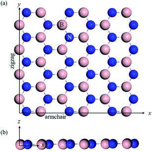 |
| | Fig. 1 Atomic structure of BNNS, (a and b) the top and side view of the computational model. | |
In the present study, all MD simulations are performed using the open-source molecular dynamic package LAMMPS (large scale atomic/molecular massively parallel simulator).31 The selection of the potential parameters is central to the accuracy of MD simulation. The Tersoff potential36,37 is often adopted to describe the interactions between B and N atoms. In accordance herewith, the potential function can be expressed as follows:
| |  | (11) |
where
| | | Vij = fc(rij)[fR(rij) + bijfA(rij)], | (12) |
| | 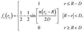 | (13) |
| | fR(rij) = A![[thin space (1/6-em)]](https://www.rsc.org/images/entities/char_2009.gif) exp(−λ1rij), exp(−λ1rij), | (14) |
| | fA(rij) = −B![[thin space (1/6-em)]](https://www.rsc.org/images/entities/char_2009.gif) exp(−λ2rij), exp(−λ2rij), | (15) |
| |  | (16) |
| |  | (17) |
| |  | (18) |
Here, E is the energy of the system, Vij is the pair energy of the pair of atoms, the indices i and j run over all atoms. Further, fc is the cut-off function which is provided to limit the range of the potential to save computational resources for the MD simulations,33 is the repulsive pair potential which contains the orthogonalization energy when atomic wave functions overlap, and fA is the repulsive pair bonding associated with bonding,37bij is the bond angle term that depends on the local coordination of atoms around atom i, and the angle θijk is the angle between bonds ij and ik.
Till now, various sets of Tersoff parameters have been published to study different properties of BN.38–41 In our study, parameters are taken from ref. 36, which has been successfully used to describe the mechanical properties and thermal properties of hexagonal BN and cubic BN.42 Though the Tersoff potential is considered successful for the study of boron-nitride nanosystems,43 it lacks Coulomb interactions, which are necessary28,44 to include so as to describe dipole interactions between atoms.45 The long-range Coulomb interactions in this study are added by using a damped shifted force model.5,46 For our simulations, the conjugate gradient method is used to ensure that the total energy reaches a local minimum. Then, the obtained energy-minimized structure is relaxed for 50 ps (picoseconds) to reach equilibrium by using the NPT ensemble for the infinite model and the NVT ensemble for finite models. A NPT ensemble means constant number of particles, pressure and temperature, while a NVT ensemble represents a constant number of particles, volume and temperature. In addition, a time step of 0.5 femtosecond is used for all simulation processes to ensure numerical accuracy and stability.
4. Results and discussion
4.1 Piezoelectric constants under different sizes
In this section, we calculate the piezoelectric coefficient e11 of h-BN. In order to assess the size dependence of piezoelectric properties we analyze a set of similar-shaped BNNS structures of different size. To realize infinite size in MD, periodic boundary conditions are applied along the x and y directions. A 20 Å vacuum space is added in the direction perpendicular to the nanosheet so that interaction between layers can be neglected. Strain is applied by extending the MD simulation box for infinite size structures. In the case of finite structures, besides adding a 20 Å vacuum space in the direction perpendicular to the nanosheet, 100 Å vacuum spaces are added along both the x and y directions to avoid interaction between layers. The dimension of this finite structure is around 10 nm in both x and y directions. The number of atoms is 3888 corresponding to 1944 B atoms and 1944 N atoms. For finite structures, a force is applied along the macroscopic boundary. The two axial strains are calculated as (refer to Fig. 2): ε1 = (xl − x0)/x0 and ε2 = (yl − y0)/y0, where x0 and xl are the nanosheet lengths along the x-direction before and after the forced stretching and relaxation, respectively. Similarly, y0 and yl are the nanosheet lengths along the y-direction before and after the forced stretching and relaxation, respectively. The shear strain is calculated as ε6 = l/y0, where l and y0 are shown in Fig. 2.
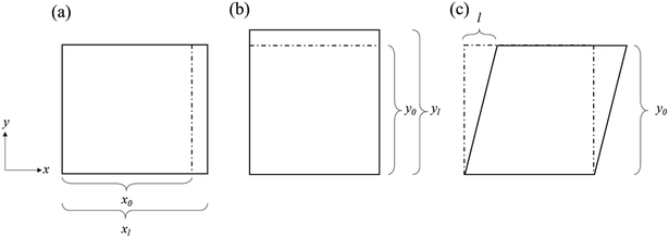 |
| | Fig. 2 The structures before strain (dashed line) and after strain (solid line). (a and b) BNNS under uniaxial strain ε1 and ε2 respectively. (c) BNNS under shear strain ε6. | |
For infinite size BNNS structures, whose macroscopic boundary shape is compatible with the unit-cell symmetry (D3h), the polarization is first calculated using eqn (8). Then, eqn (7) is used to calculate the piezoelectric constants. We obtain e11 = 1.06 × 10⁻¹⁰ C m−1 for an infinite BNNS structure which is in good agreement with previous studies as shown in Table 1. Note that DFT calculations accurately predict piezoelectric properties for infinite structures since boundary conditions are periodic in this case. In experiments or practical applications, however, spatial dimensions are finite and care must be taken in determining the influence of the exact boundary conditions and macroscopic shape on effective material properties. For this reason, we compare piezoelectric properties of BNNS structures of different sizes. In Fig. 3, three finite size BNNS structures are shown. The x- and y-directions correspond to armchair and zigzag, respectively. The BNNS structures modeled are 10 nm × 10 nm, 8 nm × 8 nm, and 6 nm × 6 nm, respectively. In the case of arbitrarily-shaped BNNS, structure is obviously incompatible with the unit-cell symmetry (D3h). Hence, we use the general form for in-plane strains, eqn (9) and (10), to calculate the piezoelectric constants of finite structures.
Table 1 Piezoelectric constants (×10−10 C m−1) for infinite BNNS
 |
| | Fig. 3 Different finite size structures of BNNS, (a–c) 10 nm × 10 nm, 8 nm × 8 nm, and 6 nm × 6 nm, respectively. | |
Previous studies indicate that uniaxial polarization only exists along the armchair direction of h-BN,17,44 and the piezoelectric properties were determined by stretching the structure along the armchair direction and recording the polarization changes,2,26,47i.e., by using e11 = ∂P1/∂ε1. When a shear strain is applied, a polarization change along the zigzag direction is obtained. Two kinds of polarization changes corresponding to different distortions can be seen in ref. 42.
The polarization along the x direction changes when uniaxial strain is applied on finite size structures, refer to Fig. 4(b) and (c). Here our MD results confirm that the shear strain ε6 = 0 after relaxation. According to eqn (9), we have P1 = α11ε1 + β12ε2, where α11 and β12 are the piezoelectric constants associated with the armchair and zigzag directions, respectively. When ε1 is applied, ε2 is calculated self-consistently in MD and vice versa. In addition, the polarization along y direction changes when applying a shear strain. Our calculations reveal that after relaxation, uniaxial strains ε1 and ε2 are both zero subject to a forced shear strain. Afterwards, the piezoelectric constant γ26 is calculated from eqn (10) as P2 = γ26ε6. Fig. 4(e) shows the calculated piezoelectric constants corresponding to the different BNNS structures. Fig. 4(e) shows that the piezoelectric constants are nearly independent of the size of the BNNS structure. Note also that the magnitude of the piezoelectric constant β12 is much larger than α11. This directional anisotropy has been observed experimentally for 2D molybdenum disulfide.48 Furthermore, the magnitude of the shear piezoelectric constant γ26 is clearly different from α11 and β12. We will now prove that the symmetry of the rectangular-shaped BNNS structures does not comply with the D3h point group symmetry. A rectangular shaped BNNS, composed of hexagonal unit cells, is shown in Fig. 5. A close inspection shows that the symmetry of the structure is 2 × m = ![[2 with combining macron]](https://www.rsc.org/images/entities/char_0032_0304.gif) = m, i.e., the rectangular-shaped BNNS structure belongs to the monoclinic m point group and the piezoelectric tensor is:
= m, i.e., the rectangular-shaped BNNS structure belongs to the monoclinic m point group and the piezoelectric tensor is:
| |  | (19) |
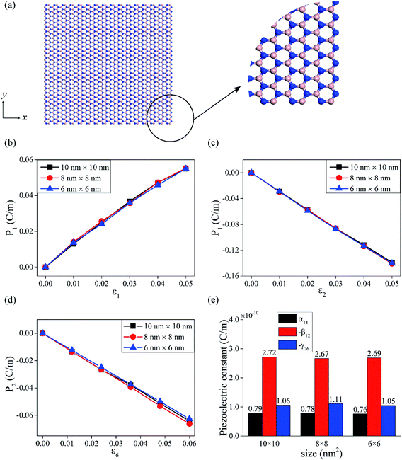 |
| | Fig. 4 (a) The atomic structure of rectangular shaped BNNS. The amplified area shows armchair and zigzag boundaries along the x and y directions, respectively. (b) The polarization changes of different size BNNS when strained along the armchair direction. (c) The polarization changes of different size BNNS when strained along the zigzag direction. (d) The polarization changes of different size BNNS when shear strain is applied. (e) The piezoelectric constants of different size BNNS calculated by using eqn (9) and (10). | |
 |
| | Fig. 5 Symmetry operator of rectangular-shaped BNNS. | |
4.2 Piezoelectric constants under different shape
In Section 4.1, we found that the MD-extracted piezoelectric constants α11, β12 and γ26 of a rectangular shaped BNNS have different magnitudes. It is obvious that the edge of a rectangular shape BNNS is armchair (zigzag) along the x (y) axis. To better understand the piezoelectric properties of different h-BN macroscopic shapes, we also examined two different hexagonal-shaped BNNSs. Note that for hexagonal-shaped BNNSs, all edges are either zigzag or armchair edges. In other words, the macroscopic boundary shape of hexagonal-shaped BNNS is compatible with the D3h unit-cell symmetry of h-BN. Fig. 6(a) shows a hexagonal-shaped BNNS whose edges are armchair. The numbers of atoms in this structure is 1986, i.e., 993 B atoms and 993 N atoms, and the number of atoms along each edge is 22. The local amplified area shows the armchair type of two connected edges. Fig. 6(b) shows a hexagonal-shaped BNNS with zigzag edges. The total number of atoms is here 2166, i.e., 1083 B atoms and 1083 N atoms, and the number of atoms along each edge is 19.
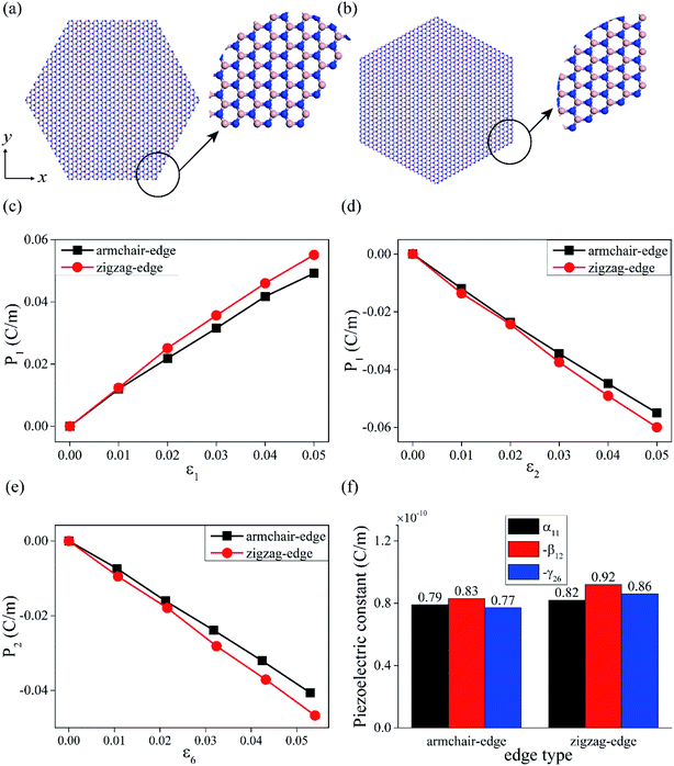 |
| | Fig. 6 (a and b) show the atomic structures of armchair and zigzag edges of a hexagonal shaped BNNS structure, respectively. (c and d) show the polarization changes of hexagonal shape BNNS structures along the x- and y-directions, respectively, as a result of stretching. (e) Shows the polarization changes when applying shear strain on a hexagonal BNNS structure. (f) Shows a histogram of the piezoelectric constants where black, red, and blue columns represent α11, −β12, and −γ26, respectively. | |
In Fig. 6(c) and (d), we show the polarization changes when stretching hexagonal-shaped BNNS along the x- and y-directions, respectively. Fig. 6(e) shows the polarization change in the presence of shear strain. As expected, the polarization changes linearly with the applied strain. The slopes of the curves determine the piezoelectric constants α11, β12 and γ26. As shown in Fig. 6(f), the piezoelectric constants of hexagonal-shaped BNNS having the same edge type (either zig-zag or armchair) are the same within computational accuracy. Our results reveal that piezoelectric constants of rectangular- and hexagonal-shaped structures are different reflecting the different symmetries of the two structures, refer also to Table 2. Within computational accuracy, our results confirm that the piezoelectric constants for hexagonal-shaped BNNS are in agreement with the D3h symmetry.
Table 2 Piezoelectric constants (1 × 10⁻¹⁰ C m−1) of hexagonal-shaped BNNS
| Piezoelectric constant |
Edge type and size |
| Armchair edge 18 edge atoms |
Armchair edge 22 edge atoms |
Armchair edge 26 edge atoms |
Zigzag edge 14 edge atoms |
Zigzag edge 19 edge atoms |
Zigzag edge 25 edge atoms |
|
α
11
|
0.79 |
0.79 |
0.80 |
0.85 |
0.82 |
0.83 |
|
β
12
|
−0.82 |
−0.83 |
−0.81 |
−0.88 |
−0.92 |
−0.90 |
|
γ
26
|
−0.81 |
−0.77 |
−0.81 |
−0.85 |
−0.86 |
−0.81 |
5. Conclusions
In summary, the piezoelectric properties of 2D h-BN are studied in this paper. First, we discuss the symmetry properties of h-BN and the influence of the macroscopic geometry on the BNNS symmetry. MD simulations are carried out to calculate the piezoelectric constants of BNNS for rectangular- and hexagonal-shaped macroscopic structures. Our MD results confirm that the piezoelectric constants of an infinite size BNNS agrees well with DFT results. For finite BNNS structures, MD calculations reveal that the piezoelectric constants are nearly independent of the macroscopic size. Our results confirm that rectangular-shaped BNNS structures belong to the monoclinic m point group while hexagonal-shaped BNNS structures belong to the D3h point group. If the macroscopic geometry is arbitrary, all piezoelectric tensor components are generally non-zero and different (the zero-symmetry case). Besides symmetry discussions, we also present results for finite BNNS structures, directional anisotropy of piezoelectric tensor properties of BNNS. This work sheds light on the piezoelectric properties of 2D BNNS structures dependence on shape, size, and guidance to experimentalists in designing and optimizing 2D nanogenerators.
Conflicts of interest
There are no conflicts to declare.
Acknowledgements
YN thanks Prof. Zhenfeng Bian for support. This work was supported by the National Natural Science Foundation of China (21876114, 21761142011, 51572174), Shanghai Government (19160712900), International Joint Laboratory on Resource Chemistry (IJLRC), and Ministry of Education of China (PCSIRT_IRT_16R49). Research is also supported by The Program for Professor of Special Appointment (Eastern Scholar) at Shanghai Institutions of Higher Learning and Shuguang Research Program of Shanghai Education Committee. Shanghai Engineering Research Center of Green Energy Chemical Engineering (18DZ2254200).
References
- Z. L. Wang and J. Song, Science, 2006, 312, 242–246 CrossRef CAS PubMed.
- D. Tan, M. Willatzen and Z. L. Wang, Nano Energy, 2019, 56, 512–515 CrossRef.
- J.-H. Lee, J. Y. Park, E. B. Cho, T. Y. Kim, S. A. Han, T.-H. Kim, Y. Liu, S. K. Kim, C. J. Roh, H.-J. Yoon, H. Ryu, W. Seung, J. S. Lee, J. Lee and S.-W. Kim, Adv. Mater., 2017, 29, 1606667 CrossRef PubMed.
- R. Gao and Y. Gao, Phys. Status Solidi RRL, 2017, 11, 1600412 CrossRef.
- D. Tan, Y. Xiang, Y. G. Leng and Y. S. Leng, Nano Energy, 2018, 50, 291–297 CrossRef CAS.
- W. Wu, L. Wang, Y. Li, F. Zhang, L. Lin, S. Niu, D. Chenet, X. Zhang, Y. Hao, T. F. Heinz, J. Hone and Z. L. Wang, Nature, 2014, 514, 470–474 CrossRef CAS PubMed.
- S. Dai, M. L. Dunn and H. S. Park, Nanotechnology, 2010, 21, 445707 CrossRef PubMed.
- M. Catti, Y. Noel and R. Dovesi, J. Phys. Chem. Solids, 2003, 64, 2183–2190 CrossRef CAS.
- C. Sevik, D. Çakır, O. Gülseren and F. M. Peeters, J. Phys. Chem. C, 2016, 120, 13948–13953 CrossRef CAS.
- M. M. Alyörük, Y. Aierken, D. Çakır, F. M. Peeters and C. Sevik, J. Phys. Chem. C, 2015, 119, 23231–23237 CrossRef.
- H. L. Zhuang, A. K. Singh and R. G. Hennig, Phys. Rev. B: Condens. Matter Mater. Phys., 2013, 87, 165415 CrossRef.
- M. Neek-Amal, J. Beheshtian, A. Sadeghi, K. H. Michel and F. M. Peeters, J. Phys. Chem. C, 2013, 117, 13261–13267 CrossRef CAS.
- S. Karmakar, P. Kumbhakar, K. Maity, D. Mandal and P. Kumbhakar, Nano Energy, 2019, 63, 103831 CrossRef CAS.
- M. N. Blonsky, H. L. Zhuang, A. K. Singh and R. G. Hennig, ACS Nano, 2015, 9, 9885–9891 CrossRef CAS PubMed.
- Z. L. Wang, Mater. Today, 2017, 20, 74–82 CrossRef.
- Z. L. Wang, Sci. Am., 2008, 298, 82–87 CrossRef PubMed.
- J. Zhang and J. Zhou, Nanotechnology, 2018, 29, 395703 CrossRef PubMed.
- K. Watanabe, T. Taniguchi and H. Kanda, Nat. Mater., 2004, 3, 404–409 CrossRef CAS PubMed.
- K. Watanabe, T. Taniguchi, T. Niiyama, K. Miya and M. Taniguchi, Nat. Photonics, 2009, 3, 591–594 CrossRef CAS.
- P. Kumbhakar, A. K. Kole, C. S. Tiwary, S. Biswas, S. Vinod, J. Taha-Tijerina, U. Chatterjee and P. M. Ajayan, Adv. Opt. Mater., 2015, 3, 828–835 CrossRef CAS.
- L. Song, L. Ci, H. Lu, P. B. Sorokin, C. Jin, J. Ni, A. G. Kvashnin, D. G. Kvashnin, J. Lou, B. I. Yakobson and P. M. Ajayan, Nano Lett., 2010, 10, 3209–3215 CrossRef CAS PubMed.
- J. S. Qi, X. F. Qian, L. Qi, J. Feng, D. N. Shi and J. Li, Nano Lett., 2012, 12, 1224–1228 CrossRef CAS PubMed.
- K.-A. N. Duerloo, M. T. Ong and E. J. Reed, J. Phys. Chem. Lett., 2012, 3, 2871–2876 CrossRef CAS.
- R. Hinchet, U. Khan, C. Falconi and S.-W. Kim, Mater. Today, 2018, 21, 611–630 CrossRef CAS.
- R. Xu, X. Zou, B. Liu and H.-M. Cheng, Mater. Today, 2018, 21, 391–418 CrossRef CAS.
- J. Zhang, Nano Energy, 2019, 58, 568–578 CrossRef CAS.
- M. López-Suárez, M. Pruneda, G. Abadal and R. Rurali, Nanotechnology, 2014, 25, 175401 CrossRef PubMed.
- V. Yamakov, C. Park, J. H. Kang, K. E. Wise and C. Fay, Comput. Mater. Sci., 2014, 95, 362–370 CrossRef CAS.
- M. Lopez-Suarez, G. Abadal, L. Gammaitoni and R. Rurali, Nano Energy, 2015, 15, 329–334 CrossRef CAS.
- J. Zhang, J. Phys. D: Appl. Phys., 2017, 50, 415308 CrossRef.
- S. Plimpton, J. Comput. Phys., 1995, 117, 1–19 CrossRef CAS.
- J. Zhang, C. Y. Wang and C. Bowen, Nanoscale, 2014, 6, 13314–13327 RSC.
- J. Zhang, Nano Energy, 2017, 41, 460–468 CrossRef CAS.
- W. L. Bond, J. Phys. Chem. Solids, 1957, 3, 338 CrossRef.
- N. Ohba, K. Miwa, N. Nagasako and A. Fukumoto, Phys. Rev. B: Condens. Matter Mater. Phys., 2001, 63, 115207 CrossRef.
- J. Tersoff, Phys. Rev. B: Condens. Matter Mater. Phys., 1989, 39, 5566–5568 CrossRef PubMed.
- J. Tersoff, Phys. Rev. B: Condens. Matter Mater. Phys., 1988, 37, 6991–7000 CrossRef PubMed.
- A. Kinaci, J. B. Haskins, C. Sevik and T. Çağin, Phys. Rev. B: Condens. Matter Mater. Phys., 2012, 86, 115410 CrossRef.
- K. Matsunaga and Y. Iwamoto, J. Am. Ceram. Soc., 2001, 84, 2213–2219 CrossRef CAS.
- W. Sekkal, B. Bouhafs, H. Aourag and M. Certier, J. Phys.: Condens. Matter, 1998, 10, 4975 CrossRef CAS.
- K. Albe, W. Moller and K. H. Heinig, Radiat. Eff. Defects Solids, 1997, 141, 85–97 CrossRef CAS.
- J. H. Los, J. M. H. Kroes, K. Albe, R. M. Gordillo, M. I. Katsnelson and A. Fasolino, Phys. Rev. B, 2017, 96, 184108 CrossRef.
- S. Thomas, K. M. Ajith and M. C. Valsakumar, J. Phys.: Condens. Matter, 2016, 28, 295302 CrossRef PubMed.
- J. Zhang and S. A. Meguid, Semicond. Sci. Technol., 2017, 32, 043006 CrossRef.
- A. Govind Rajan, M. S. Strano and D. Blankschtein, J. Phys. Chem. Lett., 2018, 9, 1584–1591 CrossRef PubMed.
- C. J. Fennell and J. D. Gezelter, J. Chem. Phys., 2006, 124, 234104 CrossRef PubMed.
- N. Sai and E. J. Mele, Phys. Rev. B: Condens. Matter Mater. Phys., 2003, 68, 241405 CrossRef.
- S. K. Kim, R. Bhatia, T. H. Kim, D. Seol, J. H. Kim, H. Kim, W. Seung, Y. Kim, Y. H. Lee and S. W. Kim, Nano Energy, 2016, 22, 483–489 CrossRef CAS.
- M. Droth, G. Burkard and V. M. Pereira, Phys. Rev. B, 2016, 94, 075404 CrossRef.
Footnote |
| † These authors contribute equally to this work. |
|
| This journal is © The Royal Society of Chemistry 2020 |
Click here to see how this site uses Cookies. View our privacy policy here.  Open Access Article
 *ac and
Zhong Lin
Wang
acd
![[6 with combining macron]](https://www.rsc.org/images/entities/char_0036_0304.gif) m2 (monoclinic m) point group. Our simulation results show that the piezoelectric constants of BNNS depend strongly on the macroscopic shape, in agreement with the symmetry of the structure, but are nearly independent of the macroscopic size. The present study provides a detailed understanding of the piezoelectric properties of finite size BNNS and guidance to future experiments and optimization of 2D piezoelectric materials in general.
m2 (monoclinic m) point group. Our simulation results show that the piezoelectric constants of BNNS depend strongly on the macroscopic shape, in agreement with the symmetry of the structure, but are nearly independent of the macroscopic size. The present study provides a detailed understanding of the piezoelectric properties of finite size BNNS and guidance to future experiments and optimization of 2D piezoelectric materials in general.
![[6 with combining macron]](https://www.rsc.org/images/entities/char_0036_0304.gif) m2) point group,33 only one e-coefficient exists assuming the macroscopic boundary shape is compatible with the D3h symmetry of the h-BN unit cell. For D3h, the nonzero components of piezoelectric coefficients are employing Voigt notation34 here and in the following,
m2) point group,33 only one e-coefficient exists assuming the macroscopic boundary shape is compatible with the D3h symmetry of the h-BN unit cell. For D3h, the nonzero components of piezoelectric coefficients are employing Voigt notation34 here and in the following,


![[thin space (1/6-em)]](https://www.rsc.org/images/entities/char_2009.gif) exp(−λ1rij),
exp(−λ1rij),![[thin space (1/6-em)]](https://www.rsc.org/images/entities/char_2009.gif) exp(−λ2rij),
exp(−λ2rij),


![[2 with combining macron]](https://www.rsc.org/images/entities/char_0032_0304.gif) = m, i.e., the rectangular-shaped BNNS structure belongs to the monoclinic m point group and the piezoelectric tensor is:
= m, i.e., the rectangular-shaped BNNS structure belongs to the monoclinic m point group and the piezoelectric tensor is:


