 Open Access Article
Oxidative ionothermal synthesis for micro and macro Zn-based materials†
Francisco
Malaret
 a,
Jason
Hallett
 a and
Kyra Sedransk
Campbell
 *b
*b
aDepartment of Chemical Engineering, Imperial College London, London, SW7 2AZ, UK
bDepartment of Chemical and Biological Engineering, University of Sheffield, Sheffield, S1 3JD, UK. E-mail: k.sedransk@sheffield.ac.uk; Tel: +44(0)1142227601
First published on 13th November 2020
Abstract
Zinc oxide (ZnO) is a multifunctional nanomaterial with a wide range of applications ranging from biosensors to solar cells. It is mainly mass-produced by air-oxidising vaporised metallic zinc at high temperatures without good particle uniformity. In a quest for environmentally-benign, cost-effective and high particle uniformity fabrication methods, many strategies had been proposed. However, recent methods utilise Zn salts as starting materials, produced commercially from metallic zinc, instead of the metallic Zn itself. We demonstrate that ZnO nano–macro particles (e.g. nanorods, needles and hierarchical structures) and other compounds [Zn(OH)2, Zn5(OH)8Cl2 or Zn5(OH)6(CO3)2] form spontaneously by direct oxidation of metallic zinc in aqueous ionic liquids (1-butyl-3-methylimidazolium chloride). Further, their chemical structure and morphology can be controlled by adjusting the concentration, temperature and exposure time. The environmentally benign and tunable nature of this novel oxidative ionothermal synthesis offers potential for new avenues towards application-motivated tailoring of ZnO and other nano and macro materials fabrication.
Introduction
Zinc oxide (ZnO) has one of the greatest assortments of different particle structures among all known materials.1 This compound is one of the most important nanomaterials today, which in and of itself is a multifunctional material with a breadth of achievable physical and chemical properties, including: high chemical stability, high electrochemical coupling coefficient, a broad range of radiation absorption and significant photostability.2 These favourable properties, which depend on particle size, dimensions, and morphologies, along with their low-cost, low toxicity, high biocompatibility and high biodegradability of ZnO-based composites,3 have encouraged development of an ever increasingly wide range of applications, e.g., catalysis, optoelectronics, sensors, transducers, energy conversion and for medical sciences.4Ionic liquids (ILs) are salts with low melting points, extremely low volatilities and physical and chemical properties which can be tuned through modification of the constituent cations and anions.5,6 For these reasons, they have been targeted as an environmentally-friendly alternative capable of replacing organic solvents industrially.7 Of particular interest is their low melting, a result of poor coordination amongst the constituent ions on ILs, thereby preventing the formation of a stable crystal lattice.8 However, this does not simply yield an ‘electrolytic-like’ solution; rather, ILs can form stable and structured polar and nonpolar regions in the liquid phase due to the interplay between the strong coulombic forces between cations and anions, van der Waals and π–π interactions, and hydrogen bonding.9,10 Structural organization of IL and water are studied through spectroscopic measurements,9–11 Molecular Dynamic (MD) simulations12,13 and physicochemical properties measurements.14
Most of the commercial zinc oxide is manufactured using the French process. In this process, metallic zinc is vaporised at 1000–1400 °C and instantly air-oxidised into ZnO powder. Due to highly nonuniform crystallization conditions, many types of one-dimensional nanostructures and irregularly shaped particles are formed.15 To produce ZnO nanoparticles with high regularity in terms of particle morphology, size and spatial structure, a large array of approaches has been proposed, including modifications to the French Process to yield tetrapodal ZnO16 and several IL-based routes, such as precipitation, sol–gel, hydrothermal, nanocasting, and microwave or ultrasound-mediated methods.17–19 The great variety of preparation routes under development attests to the need to find facile, inexpensive, environmentally-benign, and scalable fabrication strategies whilst maintaining morphological control and uniformity, good throughput and high yields for large-scale synthesis of these nanomaterials.
To overcome the challenges faced by large scale production of ZnO nanoparticles, two interesting approaches have been recently explored, firstly Zn foils as a better starting material20–23 and secondly ILs as solvent,24–28 though not in combination. With the latter, synthesis of ZnO has either been achieved by using a IL containing Zn24,25 or a Zn containing salt dissolved in solution, e.g. Zn(CH3COO)2.24,26,27 It is known that water can be used to modify/break the patterns of IL self-organization29 and that the structural outcome of nanoparticles synthesised from salts in these systems depends on the water content.30,31 Additionally, it has been proposed that IL media can serve as an “entropic driver” for the spontaneous formation of high quality nanostructures.30 However, the addition of water to non-oxidising ILs to simultaneously provide an oxidising agent and to modify solvent structure in a controllable way (by adjusting the concentration) for nanomaterials synthesis has not been reported. We show how a diversity of Zn-based nano–micro materials can be obtained by Oxidative Ionothermal Synthesis (OIS), i.e. by the direct oxidation of metallic zinc in 1-butyl-3-methylimidazolium chloride [C4C1im]Cl and water solutions. Additionally, we show how to tune their morphology and chemical composition by adjusting the water concentration, temperature and exposure time. This combines to yield a low cost, energy efficient synthetic approach in a sustainable medium.
Experimental method
To assess the effect of contaminants in the [C4C1im]Cl, two IL sources were used: purity ≥98.0% (Sigma-Aldrich, referred as IL-1) which formed transparent solutions and purity 99% (Iolitec, referred as IL-2) which formed orange solutions. These chemicals were used as received. High purity water (Millipore 15 MΩ cm) was used throughout (IL dilutions, water control and sample cleaning). The solution water content was measured by Karl Fisher Titration (Mettler Toledo Volumetric KF Titrator V20 for >5 wt%; Mettler Toledo Coulometric KF Titrator C20 for <5 wt%). To dry the ILs, a Schlenk line was used at 80 °C for >48 h under vacuum. Due to the hygroscopic nature of [C4C1im]Cl a 0.42 wt% was the minimum water content achieved.Zinc (purity >99.95%, temper: as rolled, Goodfellow Cambridge Limited) disks (d = 18 mm, 0.125 mm thickness) with a single 0.8 mm diameter hole was used. The metal substrates were prepared at room temperature by washing with demineralized water, industrial methylated spirits, and acetone. After which, the samples were dried for 45 min at 105 °C, cooled in a desiccator for 30 min. Each metal coupon was immersed in the prepared solution (Table S1, ESI†) suspended by a fluorocarbon filament. The metallic surface area to liquid volume ratio was 0.2 mL mm−2 (NACE TM0169/G31-12a).32 The high temperature experiments at 120 °C containing water were carried out inside a custom-built aluminium/polyether-ether-ketone (PEEK) containers equipped with a polytetrafluoroethylene (PTFE) liner and a PEEK rod used to hold the Zn foils. They dry experiments at 120 °C were done in open containers in a vacuum oven (Binder VLD-53) with no further change in the water content. To ensure isothermal conditions for experiments at 70 °C and 120 °C (aqueous solutions), the Zn foils and the solutions were preheated separately for 1 and 2 h respectively (Thermo Scientific Heratherm).
In order to cope with differences in the zinc oxidation rates, the exposure times were adjusted according to the severity of the experimental conditions to avoid the complete oxidation of the foils, i.e. longer exposure times at low temperatures and shorter exposure times with increased temperatures. At the conclusion of the experiments, the samples were removed from the solvent and quenched in demineralized water. The metal substrates were then washed, as previously described. A suite of ex situ analyses were undertaken. The solution pH was recorded (Mettler Toledo FiveEasy™). The metal substrates were analysed by XRD (PanAlytical X’Pert Pro) using CuKα radiations (2θ = 5–110, step size 2θ = 0.033, scan step time = 44.5 s, 40 kV and 20 mA), XRF (PanAlytical Epsilon3 Xle) with a silver anode and SEM/EDX (LEO Gemini 1525 FEGSEM) operated at 20 kV unless otherwise stated. In some instances, particles were removed from the surface after the completion of all analysis for calcination and thermal gravimetric analysis (TA instrument Q500 TGA with N2, from 30 °C to 650 °C with a heating rate of 5 °C min−1 (details given in the ESI†)).
Results and discussion
The impact of [C4C1im]Cl–water mixtures was probed in this study to ascertain its role in the formation of Zn products on the surface of a Zn solid substrate. Three key compositions were tested to represent the changing solution behaviours:Residual-water case (water content 0.42 ± 0.01 wt%/3.95 ± 0.04 mol%): water molecules are dispersed in the polar regions on the IL structure.33 The dominant structure is contact ion pair (CIP).34
IL-rich case (water content 23.7 ± 0.1 wt%/75.1 ± 0.3 mol%): 3 water molecules per IL pair. At this concentration, CIP is also the dominant structure, as there are not enough water molecules to complete the hydration shell of the ions. MD simulations indicate the formation of bigger water clusters beyond this point, with the formation of solvent-shared ion pairs (ESIP).35,36 It was shown that the hydration shell for [C4C1im]+ contains 33.5 water molecules in average, while the hydration shell of chloride contains between 6–8 water molecules.37,38 Therefore, 42 water molecules would be needed at least to hydrate the [C4C1im]Cl. It is important to mention ion hydration is a dynamic phenomenon and that adding that amount of water will not necessarily result in full hydration of the species as water can form clusters as well.37 The anion and cation diffusion coefficients are still similar, suggesting ion pair formation. Beyond this point, the diffusivity rapidly increases with increasing water content (Fig. 1).
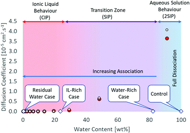 | ||
Fig. 1 Structural and diffusion properties of [C4C1im]Cl/water mixtures as a function of water concentration. Diffusion data calculated from MD simulations at 350 K.35 White circle ( ) chloride, red circle ( ) chloride, red circle ( ) [C4C1im+]. ) [C4C1im+]. | ||
Water-rich case (water content 82.4 ± 0.4 wt%/97.8 ± 0.1 mol%): 45 water molecules per IL pair. This is in the final part of the transition region where full hydration of the ionic species is just achieved. The ionic association in the aqueous solution is important and the dominant structure is double solvent separated ion pairs (2ESIP). Experimental evidence includes changes in physicochemical properties, e.g. excess partial molar enthalpy14 and changes in the relationship between molar conductivity and molar concentration (Kohlraush's empirical law39) (ESI†). With additional water, each ionic species diffuses “freely” in solution, as the diffusivity values for the cation and anion are different (Fig. 1). A control case using only water was also included (ESI†).
The experimental conditions and solution properties after the immersion experiments (pH) are summarized in Table S3 (ESI†). The different morphologies for me main structures observed by SEM are summarized in Fig. 2 and in Table S2 (ESI†). Crystallographic data and XRD patterns of the as-prepared samples are given in Fig. S20–S24 and the results are summarised in the Table S1 (ESI†).
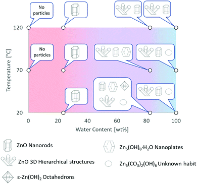 | ||
| Fig. 2 Graphical summary of Zn-based materials, obtained by direct oxidation of metallic zinc in [C4C1im]Cl solutions, as a function of experimental conditions. Further details are provided in Tables S1 and S2 in ESI.† | ||
Water-rich case
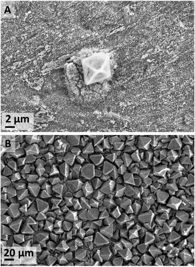
When metallic zinc foils were exposed to a high-water content [C4C1im]Cl solutions, the predominant species was ZnO at all temperatures (IL-1). At a temperature equal or lower than 70 °C Zn5(OH)8Cl2·H2O (zinc hydroxychloride monohydrate (ZHC) or Simonkolleite38–40) also formed. The occurrence of this compound is significant as it shows stable Zn–Cl complexes form at these conditions. Such compounds were not seen in our experiments at lower water content nor in a previous synthesis by Li et al.40 using the same IL and zinc acetate precursor. At 20 °C, two additional crystalline compounds were detected by XRD, namely ε-Zn(OH)2 and traces of Zn5(CO3)2(OH)6 (hydrozincite) most likely due to atmospheric CO2.41–44In the water-rich case at 20 °C (IL-1), the main two species that formed after 18 d exposure were ZnO (Fig. S4 in ESI†) and ZHC plates (Fig. S5 in ESI†). Additionally, a few ε-Zn(OH)2 octahedrons were also observed at short exposure times (Fig. 3A). However, at an increased exposure time of 44 d, many more ε-Zn(OH)2 micrometre-scale octahedrons (Fig. 3B) were observed in addition to both ZnO and ZHC. The significant increase in the quantity of ε-Zn(OH)2 at longer exposure time was not expected as this compound is generally reported to be metastable45 and would appear to be an intermediate species on the pathway to ZnO formation (Fig. 9), which is more stable thermodynamically at standard conditions (refer to ESI† for a more detailed discussion). However, the driving force (standard free energy) for the dehydration of ε-Zn(OH)2 to form ZnO at standard conditions is small in magnitude. It was noticed that ZHC was systematically detected for the cases where ε-Zn(OH)2 significantly formed, with an increase in the pH of the medium (Table S3, ESI†). This allows us to infer that as ZHC forms and chloride anions are incorporated into the ZHC crystal, hydroxide anions must remain in solution to achieve the electrical neutrality of the medium, increasing the pH of the solution. This increase in the concentration of hydroxide anions in the [C4C1im]Cl solutions with 98 mol% must be the cause of ε-Zn(OH)2 formation, which allows us to infer that by adjusting the pH, the compounds formed can be further controlled.
Halogens, such as chloride, and 1-methylimidazole are common impurities that are often present in ILs which originate from their synthesis route. There is a controversy in the scientific community regarding the effect of contaminants in the IL on the synthesis of nanoparticles.17 To verify this point, experiments were repeated using another batch of IL from another supplier (IL-2). The findings were reproducible, ε-Zn(OH)2 was not detected at short exposure times while ε-Zn(OH)2 octahedrons also formed in significant quantities at longer exposure times. These experiments show that the formation of the ε-Zn(OH)2 crystalline phase is independent of the contaminants in the IL. However, amorphous Cl-containing structures were observed at long exposure times (44 d) in the samples exposed to the IL-1 (Fig. S6 in ESI†) and not seen in the sample exposed to the IL-2. Additionally, ZnO structures did not form to a great extent in the samples exposed to IL-2 batch (Fig. S7 in ESI†). This indicates that the formation of some species at these conditions (high-water content and low temperatures) is affected by the presence of contaminants in the IL.
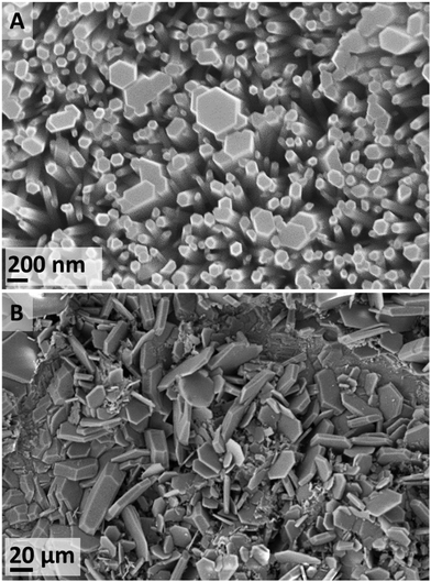
After a 4 d exposure at 70 °C (IL-1), only flat-topped hexagonal nanorods were observed (Fig. 4A). This kind of nanorod arrangement over a metallic conductor is ideal for many applications such as gas sensing, nano-generators, nano-lasers.46 By contrast, with an increased duration to 15 d, a variety of ZnO morphologies were observed, as well as trace evidence of ZHC plates (Fig. 4B). At a further increased temperature (120 °C) (IL-2), the ZnO flat-topped nanorods were again observed, albeit at shorter durations of 16 and 24 h. However, thin wool-like structures (Fig. S9 in ESI†), were also noted. At higher temperatures, the effects of the contaminants in the IL seem to not be significant.
In summary, the formation of ZnO was the predominant species at temperatures equal or higher than 70 °C. Depending on the experimental conditions, ZnO forms a diversity habits ranging from 1D nanorods to high hierarchical arrangements, flower-like structures (similar to the ones formed in the water control). The favourability of ZnO at increased temperatures has been previously reported, where the formation of ZHC has only been observed at temperatures below 90 °C38–40 and the formation of ε-Zn(OH)2 is only achieved at temperatures lower than 70 °C.37,41–43 At temperatures lower than 70 °C all these species, with different habits, might co-exist (Fig. 5). There are applications, e.g. electronics and sensors, which require a high degree of particle homogeneity; therefore, the coexistence of different habits and chemistries is undesirable. To address this requirement, the synthesis conditions could be tuned to target formation of the desired particles alone. For example, if the goal is to synthesize ZnO, the formation of the other compounds could be avoided if the synthesis is performed at higher temperatures, lower water contents or through calcination of the species formed, which easily yield ZnO.
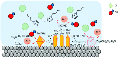 | ||
| Fig. 5 Cartoon of Zn-based micro/nano particles in [C4C1im]Cl at high water content. At this water content, chloride anions can diffuse freely to react with Zn cations to form Zn–Cl compounds. | ||
Calcination
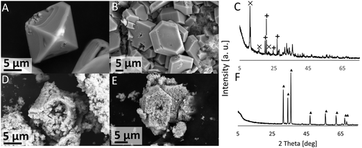
The products (ε-Zn(OH)2 and ZHC) on the coupon surface after 44 d exposure to XH2O = 0.98 solution (IL-1) at 20 °C were recovered by scratching the surface and calcined in a TGA (the thermogram, and a discussion on the thermal decomposition of these compounds, is given in the ESI†). The post-calcination products contained only ZnO (Fig. 6), generally conserved the overall crystal shape, and induced porosity. For example, the ε-Zn(OH)2 octahedrons were converted to ZnO octahedrons and the ZHC plates were converted to ZnO plates (Fig. 6).IL-Rich case
Regardless of the source of the IL used, the temperature and experimental duration, the metallic zinc substrate oxidised resulting in the formation of hexagonal ZnO (Wurtzite) (Fig. S2 in ESI†). At 20 °C, crystal growth with time is evident: 77 ± 24 nm (n = 126) diameter after 18 d exposure to 150 ± 30 nm (n = 278) after 26 d exposure (Fig. 7). This increase in particle size results in improved surface coverage of the substrate (Fig. S11 in ESI†). At 26 d exposure time, a very small fraction of the surface showed a material containing Cl detected by EDX and XRF (1750 mg kg−1) (Fig. S12 in ESI†).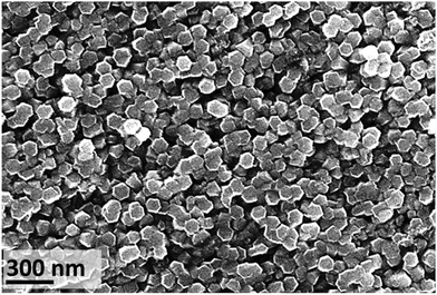 | ||
| Fig. 7 SEM image of zinc substrate after exposure to [C4C1im]Cl (IL-1, XH2O = 0.75 solution, 20 ± 1 °C) for 26 d, showing the top of hexagonal nanorods (average size 150 ± 30 nm, n = 278). | ||
It has been suggested that the imidazolium cation (of ILs) are instrumental in the preferential growth of ZnO 1D nanostructures. One proposed mechanism is where the cation adsorbs onto the surface of the growing particle by electrostatic forces and/or hydrogen bonds (between the hydrogen atom attached to the carbon at position 2 in the imidazolium ring and the oxygen atoms of the ZnO crystal [C(2)–H⋯O–Zn]); this then results in the preferential growth of the particles.47
The formation of ZnO hexagonal nanorods in the IL-rich case are hypothesized to take place in a water environment (reverse micelle) formed between the metal surface and the polar regions of the IL (Fig. 8). Water promotes the oxidation of the metallic zinc, producing an unstable Zn(OH)2 phase, which dehydrates to form ZnO. The [C4C1im]Cl creates a barrier thereby controlling the intermicellar exchange rate,40 and thus limiting excessive growth and agglomeration of ZnO particles formed. This contrasts with the rich-water (and water control) case where agglomeration was observed (high hierarchical arrangements). However, as most of the studies that probe solvent structure at metal interfaces focused on polarized electrode surfaces,48 the solvent nano-environment near the surface of unpolarized metallic zinc is unknown. Therefore, the existence of such a water nano-environment near the zinc surface awaits experimental verification.
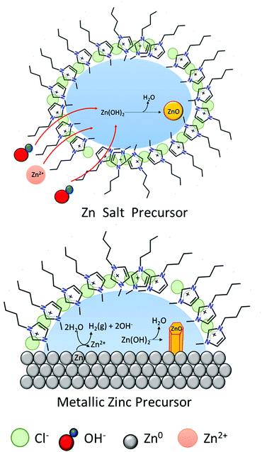 | ||
| Fig. 8 Schematic of ZnO formation in [C4C1im]Cl at low water content. Left: Zn salts as precursors.40 Right: Metallic zinc as precursor. | ||
This phenomenon is similar to a previously suggested formation of micelles whereby the cation [C4C1im]+ to capture the crystallization water from a zinc salt (e.g. Zn(CH3COO)2·2H2O). This would then form reverse micelles where the water is found in the core (polar region) in which the zinc acetate precursor dissolves. Subsequently, [OH]− ions penetrate the micelles and react with Zn2+ to form ZnO. This synthetic route using Zn salt precursors yielded ZnO spherical nanoparticles with 15–20 nm diameters40 whereas direct oxidation of zinc foils yields hexagonal nanorods.
These two routes show that despite the high chloride molality (from the [C4C1im]Cl), there is an absence of chloride-containing Zn compounds. In this mixture, as previously discussed, the chloride will preferentially remain close to the cation, [C4C1im]+, and does not react with Zn. The fact that the IL is not consumed in the ZnO formation process allows its recovery and reuse, which might lead to cost-effective and eco-friendly large-scale production processes.
Residual water case
Due to the hygroscopic nature of [C4C1im]Cl, anhydrous conditions are extremely difficult to achieve.33,49,50 At 70 °C, when metallic zinc was exposed to [C4C1im]Cl (IL-1) containing residual water, the surface was virtually unchanged, except a few irregular nanometer size features suspected to be ZnO (Fig. S13a in ESI†). Further, no significant amounts of Zn in the bulk solution were detected (Table S1, ESI†). At 120 °C (IL-2), the surface contained spherical features (Fig. S13b in ESI†) for which EDX showed traces of oxygen, likely adsorbed to the surface from the atmosphere, and no chloride. At both temperatures, the XRD patterns showed only the presence of zinc. These results confirm that the presence of water is essential for the formation of ZnO, via the oxidation of Zn at the surface coupled with the cathodic reduction of water. We can infer that in fully dry IL, no reaction will occur at temperatures equal or less than 120 °C.Overall considerations
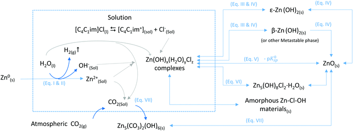
The mechanisms and thermodynamics of the different reactions are further discussed in the ESI.† The variety of Zn-compounds particles observed as a function of conditions and the exposure time can be explained by changes in the nature of the IL–water system. The degree of interaction of the chloride in [C4C1im]Cl with other species in the system can be tuned by weakening the interaction between cation and anion by the addition of a solvent, such as water. Therefore, by adjusting the water content of the mixture, the system transitions from an IL-like behaviour at low water content to a concentrated-aqueous-like behaviour at high water content. In the IL-rich case under the tested conditions, chloride does not seem to react with Zn to form Zn-chloride containing solids whereas in the water-rich region, such materials are formed. The nature of the solvent has a great influence in the nucleation and growth processes of the micro/nanomaterials particles obtained by Oxidative Ionothermal Synthesis (OIS), leading to a diversity of compounds with different chemical compositions, morphologies and sizes (Fig. 9).The chemical reactions of the different conversion paths of metallic zinc into ZnO in [C4C1im]Cl/water systems, as shown in Fig. 9, are given below:
I. Zn0(s) → Zn2+(sol) + 2e−
II. 2H2O(l) + 2e− → H2(g) + 2OH−(sol)
III. Zn2+(sol) + 2OH−(sol) ↔ Zn(OH)2(sol)
IV. ε-Zn(OH)2(s) ⇆ Zn(OH)2(sol) ⇆ β-Zn(OH)2(s) → ZnO(s) + H2O (ref. 45)
V. ZnO(S) + H2O → Zn2+ + 2HO− (ref. 51)
VI. 5Zn2+ + 8OH− + 2Cl− + H2O → Zn5(OH)8Cl2·H2O (ref. 52 and 53)
VII. 5ZnO + 2CO2 + 3H2O ⇆ Zn5(CO3)2(OH)6 (ref. 41)
Conclusions
We show in this work an Oxidative Ionothermal Synthesis (OIS) of Zn-based nano/micro materials (both crystalline and amorphous) by direct oxidation of metallic zinc in [C4C1im]Cl and water mixtures. By adjusting the water content, temperature and exposure time, different species such as ε-Zn(OH)2, Zn5(OH)8Cl2·H2O and Zn5(CO3)2(OH)6, that can be used as intermediates for ZnO nano/micro materials, are obtained.The occurrence of the difference chemical species is as follows:
• Zinc oxide (ZnO) was detected in water and [C4C1im]Cl/water at all experimental conditions tested except in neat IL (residual water case). Hexagonal ZnO nanorods are the predominant specie in the IL-rich case, while a diversity of different morphologies (hierarchical structures, rods, needles) were observed in the water-rich case.
• Zinc chloride hydroxide monohydrate (Zn5(OH)8Cl2·H2O) formation was only observed in [C4C1im]Cl at high water content (98 mol%) and at temperatures below 70 °C.
• Zinc hydroxide (ε-Zn(OH)2) was only observed in [C4C1im]Cl at high water content (98 mol%), 20 °C and long exposure time.
• Zinc carbonate hydroxide (Zn5(CO3)2(OH)6) traces were observed only at 20 °C in water and in aqueous [C4C1im]Cl (IL-2) and high water content (98 mol%), most likely due to atmospheric CO2.
The use of IL and water mixtures for making nanoparticles via direct oxidation of metals (OIS) might be used to synthetize materials-by-design (as hetero-structures, core–shell structures or metals with modified surfaces) with physicochemical properties tailored to meet industrial relevant needs. Additionally, the use of these solvents in combination with metals could lead to a more cost-effective and environmentally friendly processes for large-scale synthesis of a wide range of nano and micro materials. This approach might be used not only for Zn-based nano–micro materials, but also extended to other metals.
Conflicts of interest
A patent has been applied for in the United Kingdom by Nanomox Ltd with F. M., K. C. and J. H. as named inventors. The patent application number is GB2009470.2.Notes and references
- A. Kolodziejczak-Radzimska and T. Jesionowski, Materials, 2014, 7, 2833–2881 CrossRef CAS.
- S. S. Kumar, P. Venkateswarlu, V. R. Rao and G. N. Rao, Int. Nano Lett., 2013, 3, 30 CrossRef.
- L.-H. Zhao, R. Zhang, J. Zhang and S.-Q. Sun, CrystEngComm, 2012, 14, 945–950 RSC.
- Ü. Özgür, Y. I. Alivov, C. Liu, A. Teke, M. A. Reshchikov, S. Doǧan, V. Avrutin, S. J. Cho and H. Morko, J. Appl. Phys., 2005, 98, 1–103 CrossRef.
- T. Welton, Synthesis, 1999, 2071–2084 CAS.
- J. P. Hallett and T. Welton, Chem. Rev., 2011, 111, 3508–3576 CrossRef CAS.
- C. J. Clarke, W. C. Tu, O. Levers, A. Bröhl and J. P. Hallett, Chem. Rev., 2018, 118, 747–800 CrossRef CAS.
- P. M. Dean, J. M. Pringle and D. R. MacFarlane, Phys. Chem. Chem. Phys., 2010, 12, 9144–9153 RSC.
- K. Saihara, Y. Yoshimura, S. Ohta and A. Shimizu, Sci. Rep., 2015, 5, 1–10 Search PubMed.
- S. Cha, M. Ao, W. Sung, B. Moon, B. Ahlström, P. Johansson, Y. Ouchi and D. Kim, Phys. Chem. Chem. Phys., 2014, 16, 9591–9601 RSC.
- H. Abe, N. Hatano, Y. Ima, S. Ohta, A. Shimizu and Y. Yoshimura, Open J. Phys. Chem., 2011, 1, 70–76 CrossRef.
- J. N. A. Canongia Lopes and A. A. H. Pádua, J. Phys. Chem. B, 2006, 110, 3330–3335 CrossRef CAS.
- W. Jiang, Y. Wang and G. A. Voth, J. Phys. Chem. B, 2007, 111, 4812–4818 CrossRef CAS.
- K. Miki, P. Westh, K. Nishikawa and Y. Koga, J. Phys. Chem. B, 2005, 109, 9014–9019 CrossRef CAS.
- S. Mahmud, M. J. Abdullah, G. A. Putrus, J. Chong and A. K. Mohamad, Synth. React. Inorg., Met. Nano-Met. Chem., 2006, 36, 155–159 CrossRef CAS.
- T. Charinpanitkul, P. Nartpochananon, T. Satitpitakun, J. Wilcox, T. Seto and Y. Otani, J. Ind. Eng. Chem., 2012, 18, 469–473 CrossRef CAS.
- J. Łuczak, M. Paszkiewicz, A. Krukowska, A. Malankowska and A. Zaleska-Medynska, Adv. Colloid Interface Sci., 2016, 230, 13–28 CrossRef.
- J. Łuczak, M. Paszkiewicz, A. Krukowska, A. Malankowska and A. Zaleska-Medynska, Adv. Colloid Interface Sci., 2016, 227, 1–52 CrossRef.
- X. Kang, X. Sun and B. Han, Adv. Mater., 2016, 28, 1011–1030 CrossRef CAS.
- S. Cho, S. Kim, J. W. Jang, S. H. Jung, E. Oh, B. R. Lee and K. H. Lee, J. Phys. Chem. C, 2009, 113, 10452–10458 CrossRef CAS.
- Y. Ji, Mater. Lett., 2015, 138, 92–95 CrossRef CAS.
- M. D. L. Balela, C. M. O. Pelicano and Z. Lockman, J. Mater. Sci., 2017, 52, 2319–2328 CrossRef CAS.
- W. K. Tan, K. Abdul Razak, Z. Lockman, G. Kawamura, H. Muto and A. Matsuda, Mater. Lett., 2013, 91, 111–114 CrossRef CAS.
- H. Zhu, J. F. Huang, Z. Pan and S. Dai, Chem. Mater., 2006, 18, 4473–4477 CrossRef CAS.
- D. P. Liu, G. D. Li, Y. Su and J. S. Chen, Angew. Chem., Int. Ed., 2006, 45, 7370–7373 CrossRef CAS.
- M. Movahedi, E. Kowsari, A. R. Mahjoub and I. Yavari, Mater. Lett., 2008, 62, 3856–3858 CrossRef CAS.
- X. Zhou, Z.-X. Xie, Z.-Y. Jiang, Q. Kuang, S.-H. Zhang, T. Xu, R.-B. Huang and L.-S. Zheng, Chem. Commun., 2005, 5572–5574 RSC.
- J. D. Souza, V. S. Souza and J. D. Scholten, ACS Sustainable Chem. Eng., 2019, 7(9), 8090–8098 CrossRef CAS.
- Y. Jeon, J. Sung, D. Kim, C. Seo, H. Cheong, Y. Ouchi, R. Ozawa and H. O. Hamaguchi, J. Phys. Chem. B, 2008, 112, 923–928 CrossRef CAS.
- M. Antonietti, D. Kuang, B. Smarsly and Y. Zhou, Angew. Chem., Int. Ed., 2004, 43, 4988–4992 CrossRef CAS.
- J. Yin, F. Gao, C. Wei and Q. Lu, Sci. Rep., 2014, 4, 3736 CrossRef.
- ASTM, ASTM Int., 2012, G31-12a, 1–10 Search PubMed.
- J. E. S. J. Reid, A. J. Walker and S. Shimizu, Phys. Chem. Chem. Phys., 2015, 17, 14710–14718 RSC.
- Y. Marcus and G. Hefter, Chem. Rev., 2006, 106, 4585–4621 CrossRef CAS.
- A. A. Niazi, B. D. Rabideau and A. E. Ismail, J. Phys. Chem. B, 2013, 117, 1378–1388 CrossRef CAS.
- P. Stange, K. Fumino and R. Ludwig, Angew. Chem., Int. Ed., 2013, 52, 2990–2994 CrossRef CAS.
- M. V. Fedotova, S. E. Kruchinin and G. N. Chuev, J. Mol. Liq., 2017, 247, 100–108 CrossRef CAS.
- Y. Wang, W. Zhu, K. Lin, L. Yuan, X. Zhou and S. Liu, J. Raman Spectrosc., 2016, 47, 1231–1238 CrossRef CAS.
- J. Bowers, C. P. Butts, P. J. Martin, M. C. Vergara-Gutierrez and R. K. Heenan, Langmuir, 2004, 20, 2191–2198 CrossRef CAS.
- K. Li, H. Luo and T. Ying, Mater. Sci. Semicond. Process., 2011, 14, 184–187 CrossRef CAS.
- P. Kowalik, M. Konkol, K. Antoniak-Jurak, W. Próchniak, P. Wiercioch, M. Rawski and T. Borowiecki, Mater. Res. Bull., 2015, 65, 149–156 CrossRef CAS.
- M. Bitenc, P. Podbršček, P. Dubek, S. Bernstorff, G. Draić, B. Orel and Z. C. Orel, CrystEngComm, 2012, 14, 3080–3088 RSC.
- M. Y. Nassar, M. M. Moustafa and M. M. Taha, RSC Adv., 2016, 6, 42180–42195 RSC.
- M. Wang, B. Zhao, S. Xu, L. Lin, S. Liu and D. He, Chem. Commun., 2014, 50, 930–932 RSC.
- F. Demoisson, R. Piolet and F. Bernard, Cryst. Growth Des., 2014, 14, 5388–5396 CrossRef CAS.
- Ü. Ozgur, D. Hofstetter and H. Morkoç, Proc. IEEE, 2010, 98(7), 1255–1268 Search PubMed.
- L. Wang, L. Chang, B. Zhao, Z. Yuan, G. Shao and W. Zheng, Inorg. Chem., 2008, 47, 1443–1452 CrossRef CAS.
- R. Hayes, G. G. Warr and R. Atkin, Chem. Rev., 2015, 115, 6357–6426 CrossRef CAS.
- A. M. O’Mahony, D. S. Silvester, L. Aldous, C. Hardacre and R. G. Compton, J. Chem. Eng. Data, 2008, 53, 2884–2891 CrossRef.
- A. Maiti, A. Kumar and R. D. Rogers, Phys. Chem. Chem. Phys., 2012, 14, 5139–5146 RSC.
- Y. Li, Y. Zou and Y. Hou, Cryst. Res. Technol., 2011, 46, 305–308 CrossRef CAS.
- H. Tanaka, A. Fujioka, A. Futoyu, K. Kandori and T. Ishikawa, J. Solid State Chem., 2007, 180, 2061–2066 CrossRef CAS.
- S. Cousy, N. Gorodylova, L. Svoboda and J. Zelenka, Chem. Pap., 2017, 71, 2325–2334 CrossRef CAS.
Footnote |
| † Electronic supplementary information (ESI) available: Further information about particle calcination, solvent structure, chemical reactions and thermodynamic aspects. Additional SEM images of species of interest. XRD spectra. Summary of experimental conditions. See DOI: 10.1039/d0ma00660b |
| This journal is © The Royal Society of Chemistry 2020 |

