 Open Access Article
Creative Commons Attribution 3.0 Unported Licence
Metal particle-free inks for printed flexible electronics
Wendong
Yang
 *ab,
Emil J. W.
List-Kratochvil
 ac and
Changhai
Wang
b
aHelmholtz-Zentrum Berlin für Materialien und Energie GmbH, Forschergruppe Generative Fertigungsprozesse, Hahn-Meitner-Platz 1, 14109 Berlin, Germany. E-mail: emil.list-kratochvil@helmholtz-berlin.de; wendong.yang@helmholtz-berlin.de
bInstitute of Sensors, Signals and Systems, School of Engineering and Physical Sciences, Heriot-Watt University, Edinburgh, EH14 4AS, UK. E-mail: c.wang@hw.ac.uk
cHumboldt-Universität zu Berlin, Institut für Physik, Institut für Chemie, IRIS Adlershof, Brook-Taylor-Straße 6, 12489 Berlin, Germany. E-mail: emil.list-kratochvil@hu-berlin.de
First published on 14th November 2019
Abstract
Metal particle-free inks, composed of metal salts or metal complexes and volatile solvents, have received significant attention due to their flexibility in preparation, excellent stability and a relatively low sintering temperature in comparison with metal nanoparticle-based inks (nano inks). Formulating such inks has the potential to solve the problems occurring in the synthesis and patterning processes of metal nano inks by careful design of the ink formulation. In this paper, the development of silver and copper particle-free inks is reviewed, with particular attention on the ink formulation, patterning and post-treatment methods. The challenges are also discussed. The properties of the silver particle-free ink vary primarily with the type of silver precursor and the ligand used to solubilize and stabilize it. Highly conductive silver films with controlled microstructure features can be obtained at low sintering temperatures by the selection of appropriate precursor materials and ligands. Printability is also an issue to be solved to obtain patterns with high resolution for practical applications of these inks, which can be realized by adjusting the fluidic properties of the ink and the printing parameters. In terms of copper particle-free inks, the precursors available for selection are very limited and most of them are based on copper(II) formate. New precursors should be exploited. Besides, new sintering methods can also be explored for energy-efficient manufacturing of flexible electronics. In this respect, self-sintering, where sintering occurs spontaneously in the patterning process, is preferred. A Cu–Ag hybrid particle-free ink is also a possible choice for low-temperature fabrication of conductive patterns due to the catalytic property of silver. Finally, it will be advantageous to exploit the possible applications of such inks in the area of electronic and energy devices.
1. Introduction
Miniaturization and flexibility are becoming the development trend of electronic products, which stimulates a new way of fabricating such products. Printed flexible electronics, a technology using conductive ink and flexible substrates for continuous production of large-area electronic devices at low cost, has attracted much attention and has seen rapid development.1,2 Compared to conventional microelectronics, printed flexible electronics has two advantages. Firstly, the technology brings about the possibility of manufacturing electronic devices in a much simpler, faster, more cost-effective and eco-friendly way.3 This is because it is, in essence, a direct additive deposition process to transfer the ink to the substrate consuming minimal material and with minimal process waste. Secondly, it expands the range of the substrate materials, like polymers and paper, which allow electronic devices with some advantageous features.4 For instance, when a plastic film or paper is used as the substrates, electronic products can be flexible and lightweight; when fabric materials are used as the substrates, the electronic products become wearable.3 The applications of printed flexible electronics cover a wide range from medicine and biology to electronic and energy technology as well as space exploration in circuit boards,5 thin-film solar cells,6 flexible displays and sensors.7,8 Following the organic-electronic-association, these applications can be categorized into five main groups, organic light emitting diode (OLED) based lighting, organic and hybrid photovoltaics, flexible displays, electronics and components (memories, batteries, wiring and interconnects, active devices and passive devices) and integrated smart systems (smart cards, RFID tags, sensors and smart textiles).9 Each category has a potentially large market.10For the development of flexible electronics three subjects need to be addressed: material development including conductive inks and flexible substrates, patterning and printing methods, and specific device design. Among these subjects, conductive inks play a central role because they are a part of the supply chain in industrialization of printed flexible electronics. Usually, these inks contain several different constituents, which can be divided into three groups: functional materials, solvents, and additives. In terms of antenna, interconnects and electrode applications a wide range of functional material classes have been developed and used: conducting polymers,11–13 carbon black,14 carbon nanotubes,15–18 graphene and graphene oxide,19–28 metal nanoparticles,29–41 metal nanowires42–44 or metal complexes,45–53 and salts.54–56 Solvents are used to disperse or dissolve the components of the ink and to adjust the viscosity and surface tension. Additives complete the required properties and functionality of the ink composition by modifying the ink properties to meet the different requirements for the printing method and the printed application.
At present, conductive inks with metal nanoparticles or nanowires (named metal nano inks) are under rapid development because of the progress in the synthesis of nanomaterials based on Au/Ag/Cu due to the good conductivity of these materials. Such inks are normally made of metal nanoparticles or nanowires, volatile solvents and surfactants. The latter two are mainly used to prevent the aggregation of the metal nanoparticles and enable the ink to be suitable for various patterning technologies. High metal loading is the key advantage of the metal nano inks, which results in high conductivity post-treatment (only a few times lower than that of the bulk metal). However, this type of ink usually has a complex synthetic process, requiring high temperatures (generally > 200 °C) to make the ink tracks very conductive, and easily agglomerates in the synthesis, printing and storage process, which limit their wide applications.
Compared to metal nano inks, metal particle-free inks have attracted great interest due to their flexibility in preparation, excellent stability and a relatively low sintering temperature (90–200 °C). As the metal exists in the ionic form in these inks, there is no aggregation during preparation and storage. These types of inks, made from specific metal salts or metal complexes and volatile solvents, can be directly transformed into pure metal patterns by a low-temperature thermal decomposition process, normally including nucleation and growth with or without nanoparticles. A low post-treatment temperature and processing time would allow various substrates to be used, and the resultant electronic products can be manufactured more rapidly with less energy usage. Given this potential, intense effort has been undertaken to developing such inks, especially for silver and copper particle-free inks. Up to now, only reviews of metal particle-based inks have been found in the literature.57–60 To fill this gap here we review the state of the art in particle-free ink development and discuss the challenges for future developments.
There are different key factors to be considered when formulating an optimal metal particle-free ink. The first factor is the performance in the application. In detail, the ink should have a high conductivity as close as possible to that of the bulk material with good adhesion to the substrates and good film morphology after low-temperature treatment. When used as electrodes in an OLED, photovoltaic or electrochemical sensor application the exact value of the work-function or redox potential of the printed metal is critical. The second factor is processability. The synthesis procedure should be simple and have high-yield. The ink should be chemically stable and have a long shelf-life. It should have good compatibility with the substrate and the printing method. The ink should be processable at temperatures below 150 °C in less than 10 minutes, or better 120 °C to be compatible with a wide range of flexible substrates.61 The third factor, and importantly, is the cost. The ink should serve for low-cost electronics. Therefore, raw material cost, the ink formulation process, but also processing temperature, time and yield, must be carefully and consequently optimized to provide a compelling advantage over conventional processes currently used in the industry.
In this paper, the development of metal particle-free inks is reviewed, with particular attention on the formulation, patterning and conversion post processing methods of silver and copper particle-free inks. The challenges are also discussed and further development should be focused on the development of new materials and processing methods, the optimization of ink formulation, and exploration of new sintering methods for energy-efficient manufacturing. Inks with low-temperature self-reducibility and metal hybrid inks would be good directions.
2. Design of ink formulation
2.1 Selection of metal precursors
A metal precursor is a metal compound that can be decomposed to the corresponding metal after post-treatment. As an important component, the selection of a suitable precursor is crucial because it determines the thermal and electrical properties of the final ink.For flexible electronics, the ultimate interest for converting the deposited metal precursor inks into the corresponding metal atom is to reduce the temperature of post-treatment to be as low as possible and to achieve the best conductivity on a wide range of flexible substrates. Considering these requirements, metal aliphatic carboxylates, unsaturated, branched and/or substituted with a hydroxyl group, are preferred because they are easy to be transformed into metal atoms at low temperature via a decarboxylation reaction.62,63 Besides, it is advantageous to use a precursor with higher metal content in the ink (10–40 wt% metal), so that a good balance between the printability of the formulated ink and the conductivity of the printed pattern can be obtained.64 The solubility of the metal precursors in common solvents is also a factor to consider in metal precursor selection.
In terms of silver particle-free inks, silver precursors can be, but are not limited to silver nitrate,65,66 silver carbonate,47 silver oxide67,68 and silver carboxylates, including silver acetate,45,46,69,70 silver citrate,71–74 silver oxalate,51 silver tartrate,75 β-ketocarboxylate silver,48,76,77 silver neodecanoate,78–81 silver 2-[2-(2-methoxyethoxy)ethoxy]acetate,82 silver hexafluoroacetylacetonate cyclooctadiene,83 silver glycolate,54 silver lactate or a derivative thereof. Overall, each precursor has its advantages and disadvantages. For instance, silver nitrate and silver acetate have a relatively high decomposition temperature and are sensitive to light. 2-[2-(2-Methoxyethoxy)ethoxy]acetate silver is stable but has a relatively complex synthesis process. Recently, silver oxalate and silver citrate have been found to have excellent ink stability and can promote silver reduction at a relatively low temperature making them compatible with most of the polymer substrates.84
For silver nitrate, it will decompose into elemental silver, nitrogen dioxide and oxygen when heated, mainly via the following reaction:
| 2AgNO3 → 2Ag(s) + O2(g) + 2NO2(g) |
The thermal conversion of silver carbonate to silver metal occurs via the formation of silver oxide at a temperature above 220 °C.86
| Ag2CO3 → Ag2O(s) + CO2(g) |
| Ag2O → 2Ag(s) + 1/2O2(g) |
For silver carboxylates, there is not a unified decomposition theory but is likely to be related to their molecular structures.
Some studies report that silver carboxylates thermally decompose to metallic silver and volatile products depending on the carboxylate residue in a wide range of temperatures.62 The following scheme of the decomposition reaction was proposed:
| CH3(CH2)nCOOAg → Ag + CO2 + CH3(CH2)nCH3 |
| 2RCOOAg → Ag2O + RC(O)OC(O)R → Ag + CO2 + RCOOH |
Copper is a good alternative material to silver due to its low cost, good conductivity, and the reduced electromigration effect. Copper-based inks have been developed to reduce the cost of the silver conductive inks. However, at present, there is not much research on particle-free conductive inks with copper salts as the metal precursors. This is because that most copper salts require a higher temperature to decompose and have complicated decomposition products that usually are an oxide of copper or a mixture, and it is difficult to obtain pure copper metal. Also, the mass fraction of copper in the molecular formula of the precursor is low, leading to poor electrical performance of the conductive patterns. Currently, in most cases, Cu(II) formate (Cuf) is chosen to formulate copper particle-free inks owing to its low thermal decomposition temperatures (less than 220 °C) and self-reduction ability.52,53,88–92 Besides, copper acetate, copper(II) hydroxide and copper(II) ethylene glycol carboxylates have also been used as precursors, respectively.90,93,56
For copper(II) formate, the decomposition has been shown to occur near 200 °C, yielding elemental copper, hydrogen and carbon dioxide in a stepwise cation reduction reaction with copper(I) formate as an intermediate.94,95
The decomposition products of copper acetate are complicated. In order to obtain the pure copper element, it must be protected by an inert atmosphere. Otherwise, even if the copper element is obtained, it will be oxidized quickly. And the stability of copper under heating conditions is also poor and a small amount of oxygen can lead to the oxidation of the copper produced. Lin et al. investigated the decomposition behavior of copper acetate in air.96 The result showed that the copper acetate started to decompose at a temperature of about 168 °C and the initial products were the admixture of Cu2O, CuO and Cu. Cu and Cu2O were then oxidized to CuO in air with increasing temperature.
As for gold inks, gold(I) carboxylates are stable and can be prepared by straightforward synthesis methodologies. Gold(III) β-diketonates and liquid [Au(O2CCH2(OCH2CH2)2OCH3)(nBu3P)] are good precursor materials for ink formulation.97 Gold(III) β-diketonates are very reactive and decompose readily at ambient temperatures, producing electrically conducting gold thin films.97
2.2 Solubilization method
Solvents usually have two functions in ink formulation. One is to dissolve the metal precursors, the other is to keep the ink in a fluid form for printing purposes. Water and organic solvents can be used, depending on the specific printing process, the substrates, the dry conditions and the final purpose.98 Alcohols with low molecular weight are usually selected as ink solvents because they are less toxic and easily evaporate without leaving residues in the resulting film, which is beneficial for the final conductivity. Besides, they contain hydroxyl groups with a certain amount of reduction capability which is also beneficial for film formation. Nevertheless, silver salts (apart from silver nitrate) and copper(II) formate are usually sparingly soluble or insoluble in alcohols. Therefore, improvement of solubility of these materials in volatile organic solvents is key to formulation of particle-free inks.One approach is to use ligands possessing multiple silver binding sites.99 Amines, cyanides, and thiocyanate have been considered since they can solubilize and stabilize the silver precursors in alcohol-based solvents and can increase the susceptibility of silver ion to reduction.73 However, considering the toxicity and environmental implication, amines are the main choices. The preferred amines are those substituted by one or more Cl to C6 aliphatic groups which can be substituted by hydroxyl, or a Cl to C16 linear or branched aliphatic thiol.100 They can be mono-functional amines and/or multifunctional amines such as diamines.64 For copper formate, amino-hydroxyl compounds are advantageous due to their high stability during processing and storage, and due to the fact that the decomposition of most of them occurs at sufficiently low temperatures.101 Furthermore, amino hydroxyl compounds enable good solubility of the copper complexes in glycol ether solvents, which are very suitable for inkjet printing.101
In our previous work, four monoamines and two diamines with long alkyl-chains were selected as the ligands to formulate silver particle-free inks.102 It was found that the sparingly soluble silver oxalate powder could be easily dissolved in alcohols, resulting in a soluble complex. The type of amine not only affects the solubility of the silver precursor in organic solvents but also affects the thermal sintering temperature of the formulated ink. It also has a strong influence on the morphology of the resultant film.
Similarly, to make copper(II) formate soluble in alcohols and to lower its decomposition temperature, a kind of alkanolamine, 2-amino-2-methyl-1-propanol (AMP), was selected as the ligand to produce a soluble complex and, as a result, to formulate a particle-free ink compatible with offset printing.88 A photograph of Cuf–AMP complexes dissolved in various alcohols and a nonpolar solvent (toluene) is shown in Fig. 1 to illustrate the good solubility of the complexes in alcohols.
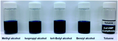 | ||
| Fig. 1 Photograph of Cuf–AMP complexes dissolved in various alcohols and toluene. In the latter case, phase separation between an upper toluene-rich phase and a lower Cuf–AMP complex phase takes place. Reproduced with permission from ref. 88. Copyright 2014, American Chemical Society. | ||
Yabuki et al. showed that the coordinated copper formate with amine diol ligands is less susceptible to oxidation, and can be sintered in an ambient atmosphere to produce films with reasonable electrical conductivities.92 The aminediol adsorbed onto the surface of copper particles in the film prevented interaction with oxygen, as shown in Fig. 2.
 | ||
| Fig. 2 Adsorption model of (a) 3-diethylamino-1,2-propanediol (DEAPD) and (b) octylamine on a copper particle. Reproduced with permission from ref. 92. Copyright 2014, Elsevier. | ||
Paquet et al. explored how the type of alkylamine affects the thermolysis of copper formate complexes (Fig. 3) and the morphology and the electrical properties of copper films derived from these complex inks.103 Correlations between the properties of the amines, such as boiling point and coordination strength, with the morphology and electrical performance of the copper films, were established. Highly conductive films could be generated from copper formate inks when the coordinating amine can direct the growth of small particles and form dense films. The work provides a basis for the molecular design of copper particle-free inks.
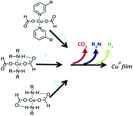 | ||
| Fig. 3 The temperature at which copper formate complexes begin to decompose is governed by the number of hydrogen bonds that can form between the amine hydrogen and the formate oxygen. Reproduced with permission from ref. 103. Copyright 2018, Royal Society of Chemistry. | ||
Table 1 gives a summary of the chemical structures of amines used in the reported metal particle-free inks. The related parameters of different amines such as molecular weight and boiling point are also given for easy comparison (the data were obtained from Wikipedia). From Table 1, it can be seen that the main types of amines include monoamines, diamines and alkanolamines. Since the decomposition temperature of aromatic amines is higher than that of aliphatic amines, aromatic amines are rarely considered for ink applications. Overall, a selected amine should have two functions, one is to increase the solubility of the metal precursors in solvents and the other is to greatly reduce the heat treatment temperature of the ink for pattern formation. Therefore, one needs to carefully check the physicochemical properties of amines before starting ink formulation work.
| Amine name | Chemical structure | Formula | MW (g mol−1) | Boiling point (°C) | Reference on the use of this amine |
|---|---|---|---|---|---|
| Note: the molecular weight and boiling point data were obtained from Wikipedia, not from the references. | |||||
| Ethylamine |

|
CH3CH2NH2 | 45.08 | 16.6 | 51, 70, 75 and 104 |
| Propylamine |

|
CH3(CH2)2NH2 | 59.11 | 47.8 | 75 |
| Isopropylamine |

|
(CH3)2CHNH2 | 59.11 | 34 | 47 and 105 |
| Butylamine |

|
CH3(CH2)3NH2 | 73.14 | 78 | 75, 102, 106 and 107 |
| Amylamine |

|
CH3(CH2)4NH2 | 87.16 | 104 | 107 |
| Hexylamine |

|
CH3(CH2)5NH2 | 101.19 | 131 | 103 and 107 |
| Heptylamine |

|
CH3(CH2)6NH2 | 115.22 | 155 | 108 |
| Octylamine |

|
CH3(CH2)7NH2 | 129.24 | 176 | 103 and 107 |
| Nonylamine |

|
CH3(CH2)8NH2 | 143.27 | 200 | 103 |
| Decylamine |

|
CH3(CH2)9NH2 | 157.30 | 217 | 103 |
| Ethylenediamine |

|
C2H4(NH2)2 | 60.1 | 116 | 72 and 73 |
| 1,2-Diaminopropane |

|
CH3CH(NH2)CH2NH2 | 74.13 | 119 | 71, 75, 102 and 109 |
| Dipropylamine |

|
(CH3CH2CH2)2NH | 101.19 | 110.7 | 108 |
| Dibutylamine |

|
(CH3CH2CH2CH2)2NH | 129.24 | 159 | 108 |
| Diamylamine |

|
[CH3(CH2)4]2NH | 157.3 | 202–203 | 108 |
| Dihexylamine |

|
[CH3(CH2)5]2NH | 185.35 | 192–195 | 108 |
| Ethanolamine |

|
HOCH2CH2NH2 | 61.08 | 170 | 46, 104 and 110 |
| Diethanolamine |

|
HN(CH2CH2OH)2 | 105.14 | 280 | 68 and 111 |
| 3-Dimethylamino-1,2-propanediol |

|
(CH3)2NCH2CH(OH)CH2OH | 119.1 | 216–217 | 53 and 92 |
| 3-Diethylamino-1,2-propanediol |

|
(C2H5)2NCH2CH(OH)CH2OH | 147.22 | 233–235 | 92 |
| 1-Dimethylamino-2-propanol |

|
CH3CH(OH)CH2N(CH3)2 | 103.16 | 121–127 | 50 |
| 2-Amino-2-methyl-1-propanol |

|
H2NC(CH3)2CH2OH | 89.14 | 165 | 88, 89 and 101 |
2.3 Fluid requirements
The fluid properties of the ink are important because these should be compatible with various patterning methods. The surface tension and viscosity of the ink not only determine the velocity, size, and stability of the ejected droplet but also affect the shape of the droplets impinging on the substrate.112 These impingement shapes establish the pattern resolution and thickness and further influence its mechanical and electronic properties. Therefore, the rheological parameters of inks, such as viscosity, surface tension and wettability of the substrate, should be controlled in the ink formulation process.Viscosity is a quantity that measures a fluid's resistance to flow, which is related to the internal friction of a moving fluid. A fluid with a high viscosity flows slowly because its molecular interrelation gives high internal friction. In contrast, a fluid that has a low viscosity flows easily since there is very little friction in the liquid when it is in motion. For the piezoelectric print heads, the ink viscosity should be in the range of 8–15 mPa s, while thermal print heads require viscosity below 3 mPa s.57 When using the ink in aerosol-jet printing methods for high resolution printing or slot-die coating for large area coating the viscosity window widens to the 0.5–2000 mPa s or to the 1–kPa s region, respectively.
Surface tension, also known as interfacial force or interfacial tension, is the force that causes the molecules on the surface of a liquid to be pushed together to minimize the area. A liquid with low surface tension easily wets or spreads across the surface of substrates. This phenomenon is useful to determine whether an ink will stay where it is deposited, and how wide after it is dried. The typical values for industrial printing heads are in the range of 25–35 dyne per cm.57
Wetting is the ability of a liquid to maintain contact with a solid surface (the substrate). If sufficient contact is achieved between the two phases, a physical interaction due to intermolecular forces develops causing the liquid to conform to the surface on a macro- and micro-scale, displacing air and thus minimizing interfacial flaws. Good wettability of a surface is a prerequisite for ensuring good adhesion between the ink and flexible substrates.
Many organic solvents, such as methanol, ethanol, isopropanol, or acetone, are of very low viscosity and contact angle/surface tension, and volatility. Their ability to wet the surface and low viscosity allow these fluids to spread rapidly.113 If it is required to print or write a small conductive line using the ink with these liquids as the main solvents, control of spreading is an issue to be solved, while the good wettability of such solvents may be beneficial for printing large area electrodes. The volatility of such solvents can cause operational issues, and ink drying in the nozzle is one of the most common failure modes with printers. Also, volatility can cause the non-uniform distribution of the solid on the substrate after drying, which will be described later. Solutions to this problem are diverse such as using cosolvents that have lower volatility or using reactive substrates.113
2.4 Stability
Stability is also an important aspect of performance. A stable ink is an ink in which all its properties remain constant over time.114 In most cases, instability is caused by the interactions between the ink components due to changes in solubility, and the interaction with the walls of the ink containers.114 For a metal-particle free ink, there's a possibility that its components could react with each other over time, resulting in the formation of metal particles, precipitation and phase separation, which is not good for long shelf-life and printing. This is especially true in the case of the inks containing reductive components such as alcohols or amines or formic acid. Therefore, in order to obtain a stable metal particle-free ink, one should carefully evaluate the solvent and ligand used. The selection should determine solvents that have good solubility and ligands with good complexing ability.Stability can be evaluated by measuring the various parameters of the ink stored for a period of time. For instance, Chen et al. investigated the stability of silver citrate particle-free inks formulated using triethanolamine, diethylamine and ethylenediamine as complexing agents.72 It was found that the ink derived from triethanolamine had an obvious colour change and silver particles were greatly generated after storing at room temperature for 60 days. The ink derived from diethylamine exhibited similar variation trends. These changes indicated that the ink components reacted with each other with increasing storage time. In contrast, the ink derived from ethylenediamine showed good stability after 60 days, and no colour changes and particle precipitation. We also evaluated the stability of various silver oxalate-amine particle-free inks.102 After storing in a refrigerator at 3 °C for 60 days, there were educts on the bottle wall of the ink formulated using butylamine, and the ink from 1,2-diaminopropane was still transparent without any colour change, implying good stability and hence long shelf life.
3. Patterning and post-treatment
3.1 Substrates
Along with the ink technologies, substrates must be designed to meet the various requirements. Ideally, such materials must present a unique balance of properties that would make it suitable for the applications. A flexible substrate must be physically and thermally stable yet flexible, impermeable, and smooth yet sufficiently adhesive, transparent, and above all economically viable.Currently, there are a number of materials that meet most of these requirements and have been used as substrates for flexible electronics. Among them, polymer films are extensively used. Compared to paper substrates, they usually have smooth surfaces, homogeneous properties, and no porosity. This is beneficial in some aspects but is not ideal in other aspects. For instance, the non-absorbing surface is not ideal for ink deposition.
Polyimide films (PI) are often used as substrates for flexible electronics because they can withstand prolonged exposure to 300 °C and still retain their flexibility. However, the cost of PI films is relatively high, and the adhesion between PI and the ink is usually poor. Polyethylene (PE), polycarbonate (PC) and polyethylene terephthalate (PET) are favorable because they are low cost and easily available. One problem with these materials is that they have a lower softening temperature (below 150 °C), and therefore they are not compatible with a high temperature sintering process required for ink metallization.
Paper-based substrates are cheap, lightweight, biodegradable and foldable. Besides, the mechanical, physical and chemical properties of paper can be altered by additives, or by changes in the manufacturing process. Therefore, it is also possible to tailor papers, adapting them to the ink.
Table 2 shows the basic properties of different substrates.115 It can be seen that each material has its advantages and drawbacks. But in general, polymer films and paper are the most favorable materials because they are light and have good flexibility.
| Glass | Metal | Paper | PET | PEN | PC | PI | PEI | PVF | |
|---|---|---|---|---|---|---|---|---|---|
| Smoothness | ++ | ++ | 0 | + | + | + | 0 | 0 | 0 |
| Temperature resistance | ++ | ++ | 0 | + | + | 0 | ++ | ++ | ++ |
| Flexibility | −− | ++ | ++ | ++ | ++ | ++ | ++ | ++ | ++ |
| Optical transmittance | ++ | −− | −− | ++ | ++ | ++ | 0 | 0 | 0 |
| Barrier | ++ | + | — | + | + | + | + | + | + |
| Price | −− | + | ++ | + | 0 | 0 | −− | — | −− |
3.2 Coffee ring effect
When ink droplets dry on a substrate surface, the solvent evaporation rate at contact lines is higher than that of the interior area. Therefore, there is a net transport of particles towards the edges of the droplets. Thus, the solute or particulate matter tends to deposit in a ring-like fashion, known as the coffee-ring effect.116 This effect will lead to a strongly non-uniform morphology and poor performance of patterned devices.Using a high boiling solvent with low surface tension, such as ethylene glycol, in silver inks can reduce the evaporative rate to decrease the coffee ring effects on printed conductive tracks.46 As shown in Fig. 4, a coffee ring is easily formed from a droplet of ink containing ethanol (Fig. 4a). However, by using mixed solvents with appropriate evaporation rates, the coffee ring effect can be eliminated (Fig. 4b).
 | ||
| Fig. 4 Surface profiles of a silver ink film after sintering: (a) coffee ring effect; (b) a flat film without the coffee ring using suitable solvent composition. Reproduced with permission from ref. 46. Copyright 2012, Royal Society of Chemistry. | ||
3.3 Patterning methods
Depending on the application several approaches can be adopted for ink deposition and patterning such as inkjet, aerosol, slot-die coating and metal transfer printing. Among them, inkjet printing is the most versatile and therefore the commonly used method. Inkjet printing allows for not only contactless additive deposition of patterned 2D features117 but also continuous large area film deposition, high printing speeds of up to 0.1 m2 s−1, and feature sizes as small as 10 μm in roll–roll (R2R) processing process.118Currently, there are two main technologies in use in contemporary inkjet printers: continuous inkjet (CIJ) and drop-on-demand (DOD) inkjet.98
In CIJ technology, a stream of charged ink droplets is continuously generated and jetted by a high-pressure pump (Fig. 5a). Then, these droplets are directed by electrostatic deflection plates and selectively printed onto the substrates. In DOD technology, there are two types, the piezoelectric and thermal DOD. In piezoelectric inkjet printing (Fig. 5b), a voltage is applied to the piezoelectric material to induce a change in the shape, generating a pressure pulse in the liquid, which forces a droplet of ink from the nozzle. In the thermal inkjet printing process, a pulse of current is passed through the heating element to cause a rapid vaporization of the ink in the chamber forming a bubble, which further causes a large pressure increase, propelling a droplet of ink onto the substrate (Fig. 5c). Although inkjet printing is the most favorable printing technology for metal particle-free inks, it still poses many challenges such as the strict range of solution parameters required to ensure successful patterning.
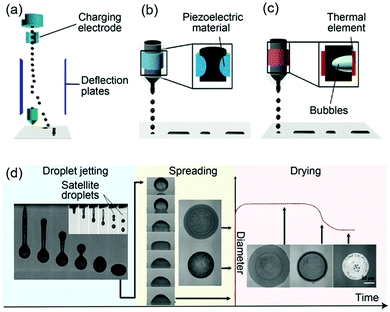 | ||
| Fig. 5 Inkjet printing principles: schematics of (a) CIJ, and DOD inkjet printing with (b) piezoelectric and (c) thermal head; (d) the complete inkjet printing process, showing the droplet jetting, spreading and drying stages. Reproduced with permission from ref. 98. Copyright 2018, Royal Society of Chemistry. | ||
In comparison with inkjet printing, aerosol jet printing is more tolerant to wide variations in ink parameters such as surface tension, viscosity, and particle size.119 In this method, the ink is first aerosolized and then flow-focused using a sheath gas to jet the produced aerosol towards a substrate, resulting in printed features with width as small as 10 μm.120
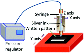
Direct ink writing (DIW) is another emerging technique with unique patterning capabilities. In this technique, a concentrated ink is extruded through a tapered cylindrical nozzle that is translated using a three-axis (x–y–z), robotic motion stage (Fig. 6).121,122 The ink filaments can maintain a similar size to the nozzle, which ranges from 0.5 μm to 1 mm.123 The printed feature dimensions are determined by the ink rheology and printing parameters. Inks designed for this method can be modified for fabricating patterns using a pen-on-paper mode. Unique 3D structures can also be fabricated by this technology.
Alternatively to do a structured selective additive deposition printing by means of slot-die coating, metal transfer printing by means of a soft-lithographic process or a variety of rotary printing methods are used in the field of printed electronics for which we refer to ref. 124 and 125 for further reading.
Overall, the choice of a patterning or coating method is dependent on the application. Rheological parameters of inks, such as viscosity, surface tension and wettability, are sometimes a major issue to be addressed before launching any related printing effort. It is essential to investigate and control the so-called “Magic Triangle of Inkjet Printing Technology”, which is determined by three main components: the ink, the substrate and the print-head.126
3.4 Post-treatment
After printing, a necessary post-treatment, such as drying, curing or sintering, is required to transform the as-deposited ink into highly conductive traces. For silver or copper particle-free inks, the formation of conductive pathways is associated with the nucleation and growth of silver or copper produced from the decomposition and/or reduction of silver or copper precursors during the post-treatment. The conductivity is determined by the characteristics of the precursors and sintering parameters as well as the organic residues.Thermal sintering is usually carried out on a hotplate or in an oven. The required temperature varies from ink to ink depending on the boiling points of the organic solvents used, the dissociation temperatures of the metal precursor salts and the degree of conductive network formation. Generally, heating at 90–200 °C for 5–60 min is required to evaporate the organic solvents, induce the decomposition or reduction of the metal precursor, and to obtain sintered metal coatings with resistivity comparable to that of the bulk metal. This method is mostly adopted for silver particle-free inks. For copper particle-free inks, a protective (N2, Ar) or reducing atmosphere (formic acid or H2) is required to protect the copper nanoparticles produced from being oxidized.
Considering the temperature sensitivity of flexible substrates such as plastic films and the easy oxidization of copper nanoparticles during the post-treatment, other methods have been studied, such as photonic sintering, electrical sintering, plasma sintering, and microwave sintering.
Photonic sintering utilizes flash lamps, lasers, and other light sources which deliver energy to the targeted material to be sintered.127 Absorption of light by the printed material produces a heating effect through the dissipation of non-radiative energy and exothermic photochemical reactions. Sufficient heat causes evaporation of the solvent and decomposition or reduction of metal precursors. Photonic sintering shows much promise for large-scale manufacturing on low thermal diffusivity substrates, such as plastic and paper. This method can process copper in an ambient atmosphere without oxidation if the ink is properly designed. Araki et al. formulated copper particle-free inks using copper formate/acetate/oleate as the precursor.111 Based on the light absorption ability of the inks (Fig. 7), they adopted the photonic sintering method for the ink metallization. The formed wires showed a low resistivity of 56 μΩ cm.
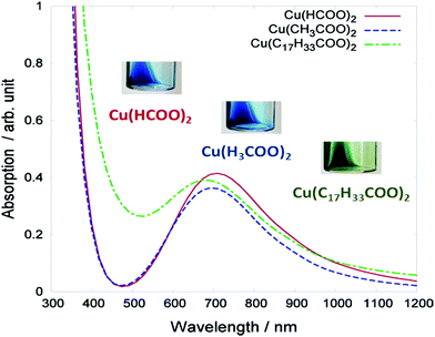 | ||
| Fig. 7 Absorption spectra of the three types of copper complex ink: copper formate Cu(HCOO)2, copper acetate Cu(CH3COO)2, and copper oleate Cu(C17H33COO)2. The inset photographs display the visual color of the inks. Reproduced with permission from ref. 111. Copyright 2013, American Chemical Society. | ||
Electrical sintering is a method by applying a voltage over the printed structure that causes current flow through the structure, leading to local heating within the film.57 The resistivity of the patterned film is determined by the sintering voltage used. The main advantages of this method are the short sintering time, which can be less than 1 min, depending on the geometry of the printed area, reduced damage to the substrate due to area-specific heating and real-time monitoring of the sintering process through current measurements. The ability to monitor while sintering allows the desired conductivity to be achieved in a controlled manner. However, electrical sintering requires contact with the printed film, which may not be possible for some applications. Electrical sintering is applicable to metal nanoinks and some other conductive materials. For metal particle-free inks, a pre-treatment is required before using this technology.128
Plasma sintering is performed by exposure of printed patterns to low-pressure argon plasma and electron-cyclotron resonance (ECR) plasma.57 The sintering process shows a clear evolution starting from the top layer into the bulk. This method has been applied to plastic substrates, and the obtained resistivity of the printed patterns is 10 times higher compared to the resistivity of bulk silver. Also, if hydrogen is used as the feed gas, the plasma can have a reduced effect. The disadvantages of plasma sintering is that selective sintering is hard to realize and is achievable in R2R processing with difficulty due to a reduced pressure and a longer processing time.129
Microwave sintering is also a promising method. However, this method is only successful if the thickness of the printed film is in the penetration depth range of the microwave radiation (1–2 μm at 2.54 GHz).127 This method is particularly attractive when polymer substrates are used, as they are almost transparent to microwave radiation, leading to localized heating whilst ensuring minimal damage to the substrate. Vaseem et al. formulated a transparent and stable ink based on a silver–ethanolamine–formate complex (SEFC). The electrical property was examined with thermal annealing and microwave-plasma sintering. The results showed that microwave-plasma irradiation facilitated the sintering and interconnecting of particles and could result in dense and uniform films (Fig. 8b).130 In the case of thermal annealing, the single-coating film on glass shows a conductivity of ∼1.7 × 10⁴ S cm−1 at 120 °C, and 5.5 × 10⁴ S cm−1 at 200 °C (Fig. 8c). With successive over-coating and sintering, the conductivity was substantially improved, with a value of 9 × 10⁴ S cm−1 (6 times lower than that of bulk silver) when sintered at temperatures above 180 °C. In contrast to thermal annealing, microwave-plasma irradiation resulted in a comparable conductivity of 4.1 × 10⁴ S cm−1 even for a short exposure time of 1 min (Fig. 8d).
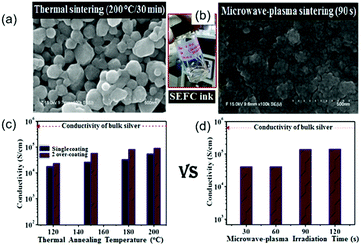 | ||
| Fig. 8 Comparison of the effects of thermal annealing (left) and microwave-plasma sintering (right) on the surface morphology and conductivity of the films deposited on glass with a SEFC-based ink. Reproduced with permission from ref. 130. Copyright 2016 Elsevier. | ||
Since each type of sintering techniques uses different equipment and has a different mechanism, it is difficult to evaluate which one is better and suitable for every ink, every substrate, and every application. However, it should be kept in mind that the post-processing step is an essential part when it comes to the total cost of ownership of the entire process and thereby using existing low-cost thermal curing and sintering processes will lower the industrial entrance barrier for a novel ink type.
4. State of the art
4.1 Silver-based particle-free inks
Silver-based particle-free inks could be made from organic silver salts or silver complex precursors and solvents with or without additives.Silver neodecanoate was first selected as a precursor to form particle-free conductive inks.78,79 The molecular formula is C10H19AgO2, which has a tertiary ligand, making it more soluble in xylene or toluene than that with secondary or primary ligands. Dearden et al. reported a low curing temperature silver particle-free ink for ink-jet printing. The ink was formulated by dissolving silver neodecanoate in xylene, and was shown to begin to decompose to silver at 125 °C with a maximal decomposition rate at 200 °C.78
Valeton et al. fabricated silver conductive patterns by printing or spinning a silver neodecanoate ink on PET substrates and using ultraviolet irradiation and subsequent treatment with hydroquinone solution.79 The conductivity was 10% of that of bulk silver. The treatment process was carried out at room temperature, which allowed low glass transition temperature polymeric substrates, such as PET, to be used. Fig. 9a shows the redox reaction between the silver neodecanoate and deprotonated hydroquinone. Fig. 9b shows two PET-based samples prepared by spin-coating and inkjet printing.
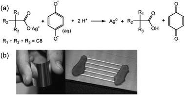 | ||
| Fig. 9 (a) Redox reaction between silver neodecanoate and hydroquinone. The reaction is facilitated by the partial deprotonation of hydroquinone in water; (b) a sample prepared by spin-coating the ink onto 50 μm thick PET foil. The high reflectivity of the sample demonstrated the silvery nature of the final coating. The picture on the right shows a sample with five inkjet printed lines on PET. Reproduced with permission from ref. 79. Copyright 2010, Royal Society of Chemistry. | ||
Arnold et al. reported an ink consisting of silver neodecanoate, ethyl cellulose and solvents for screen printing.80 The printed traces had exceptional electrical (between 8.4 and 20 μΩ cm) and mechanical properties after thermal or photonic sintering, with a rough and porous morphology from photonic sintering and a dense and smooth morphology from thermal sintering. The key factor in these properties results from the interaction between the ethyl cellulose and the as-produced silver within the traces.
Then, Jahn et al. reported a particle-free silver ink based on silver(I) 2-[2-(2-methoxyethoxy)ethoxy]acetate.82 The ink was stable in air, had a silver content of 9.1 wt% and could be used for piezo ink-jet printing. The printed, photochemically sintered silver features on PET substrates showed a favorable conductivity of 3.70 μΩ cm and superior adhesion to the substrates. A 3D profile of a single dried and sintered droplet is given in Fig. 10a and b respectively. It can be seen that, after sintering, the patterns of the inkjet droplets were composed of a multiplicity of silver particles rather than a homogeneous layer. A SEM image also showed this inhomogeneous arrangement (Fig. 10c). Fig. 10d–f show the SEM images of a printed layer and a sintered silver layer (5 min, 250 °C).
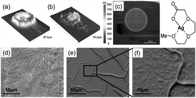 | ||
| Fig. 10 (a and b) The 3D profilometer image of an inkjet printed, dried and sintered (250 °C, 1 min) droplet of the silver(I) 2-[2-(2-methoxyethoxy)ethoxy]acetate ink; (c) SEM image of a sintered (250 °C, 1 min) droplet; (d–f) SEM images of the printed layer and sintered silver layer (5 min, 250 °C). Reproduced with permission from ref. 82. Copyright 2010, American Chemical Society. | ||
In 2011, Wu et al. formulated a particle-free silver ink in a mixed solvent by using 1-dimethylamino-2-propanol (DP) as both the protecting and reducing agents for silver nitrate.50 The formulated ink easily became silver at low sintering temperatures, and continuous silver lines with a resistivity of 17.3 ± 4.4 μΩ cm were obtained at 100 °C by inkjet printing. The resistivity is quite close to that of bulk silver.
Cai et al. prepared silver micropatterns on polyimide substrates by a laser direct writing technique using a particle-free ink.67 The ink was formulated in methanol from a complex composed of a silver oxide and ammonium carbamate. The approach relied on laser absorption and thermal energy transport in the ink to induce the decomposition of silver complex and the sintering of silver particles.
At a laser power of 0.1 W, the written silver ink started to decompose to silver. The resistivity of silver conductors fabricated at a laser power of 0.5 W was about four times that of bulk silver. Fig. 11 shows the formulation, deposition and metallization processes of the ink and the images of the written silver films.
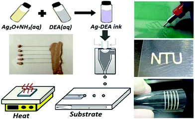 | ||
| Fig. 11 The formulation, deposition and metallization processes of the ink and the images of the written silver conductive films. Reproduced with permission from ref. 68. Copyright 2012, American Chemical Society. | ||
In 2012, Chen et al. developed a particle-free silver ink with self-reduction ability to generate highly conductive silver films on PET sheets.68 The ink, suitable for inkjet printing or direct-writing, was formulated by mixing a silver ammonia solution of silver oxide and diethanolamine (DEA) with a self-decomposable capability. After heating at temperatures above 50 °C, DEA was decomposed into formaldehyde, which reduced silver ammonia ions into silver nanoparticles. The resistivity of the printed tracks was 6 μΩ cm, 4 times that of bulk silver.
Walker et al. designed a low-viscosity and highly conductive particle-free silver ink based on a modified Tollens' process using silver acetate, ammonium hydroxide, and formic acid.45 The ink was stable and suitable for a wide range of patterning techniques such as direct-writing, inkjet-printing and airbrush-spraying. The printed electrodes exhibited a conductivity equivalent to that of bulk silver after annealing at 90 °C, which was attractive to plastic, paper or textile-based substrates for electronic applications. Fig. 12a shows the key constituents in the initial solution, ink, and the printed features. Fig. 12b shows an optical image of the silver ink and Fig. 12c shows the printed conductive silver lines (∼5 μm wide).
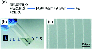 | ||
| Fig. 12 (a) Key constituents in the initial solution, ink, and printed features; (b) optical image of the silver ink in a scintillation vial; (c) conductive silver lines printed on a silicon substrate via direct-writing technology using a 100 nm nozzle. Reproduced with permission from ref. 45. Copyright 2012, American Chemical Society. | ||
Similarly, using silver acetate as a precursor, ethylamine and ethanolamine as complexing agents, formic acid as a pH regulator and reducing agent, Mohammad Vaseem et al. formulated a stable particle-free ink, which can produce highly conductive silver films with a uniform morphology and excellent adhesion at 150 °C for 30 minutes.69 Radio frequency inductors, which are highly sensitive to metal quality, were demonstrated. Fig. 13a illustrates the procedure for the formulation of a silver–ethylamine–ethanolamine–formate complex based ink and the involved chemical reaction. Fig. 13b presents the thermal reduction process of the printed ink.
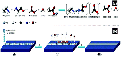 | ||
| Fig. 13 An illustrative procedure for the formulation of a silver–ethylamine–ethanolamine–formate complex based ink. (a) Chemical reaction involved in the formulation of the ink; (b) schematic presentation of the thermal reduction process for printed ink conversion to silver metallic phase and chemical reaction represented by the ball-and-stick model. Reproduced with permission from ref. 69. Copyright 2016, American Chemical Society. | ||
Bhat et al. formulated a highly conductive particle-free ink using silver acetate as a precursor, ethylamine and ammonia as complexing agents, formic acid as a reducing agent, 2% HEC as a viscosifier, dispersing agent and stabilizer, and ethanolamine as an anticlogging additive for nozzle-jet printing.70 The ink showed prolonged stability especially at lower temperatures. The printed films showed a smooth surface morphology with good adhesion and conductivity. The spin-coated film on glass annealed at 60 °C and the nozzle-jet printed film on PET sintered at 75 °C have conductivities of 93.46 μΩ cm and 36.50 μΩ cm, respectively, only one-order-of-magnitude lower than that of bulk silver.
Chang et al. developed a particle-free silver ink via a complexing process of silver carbonate and isopropylamine in a glycol–water mixture.47 Silver ions in the ink was reduced to metallic silver by glycol in the sintering process. Meanwhile, the silver–amide complex was decomposed to silver oxide and then was reduced to silver. The two reaction mechanisms are shown in Fig. 14a, where the reduction of silver oxide plays a major role. The viscosity and surface tension of the ink were 13.8 mPa s and 36.9 mN m−1 respectively. After writing the ink on a polyimide (PI) substrate and sintering at 150 °C for up to 60 minutes, the formed film showed the lowest resistivity of 18 μΩ cm and had a continuous morphology with some pores and voids (Fig. 14b). However, the ink was unstable in air due to the easy decomposition of the silver–amide complex.
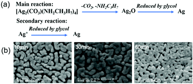 | ||
| Fig. 14 (a) Two main reaction mechanisms of the silver carbonate–amide complex ink during sintering; (b) SEM images of the conductive film sintered for 10, 30 and 60 minutes. Reproduced with permission from ref. 47. Copyright 2012, Royal Society of Chemistry. | ||
Nie et al. formulated a particle-free silver ink through a complexing process of silver citrate and 1,2-diaminopropane for printing on PET substrates.71 The ink had excellent stability with a shelf life of more than 60 days (Fig. 15) and good printability on an ordinary commercial inkjet printer. Owing to the complexation of silver citrate and 1,2-diaminopropane, the ink could be cured at 135 °C, which was much lower than the decomposition temperature of silver citrate. The printed film showed a resistivity of 17 μΩ cm after sintering at 150 °C for 50 minutes and possessed excellent adhesive properties.
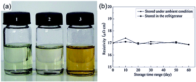 | ||
| Fig. 15 (a) Optical image of silver citrate particle-free inks: (1) freshly prepared; (2) preserved in the refrigerator for 60 days; (3) preserved under ambient conditions (25 °C) for 60 days; (b) variation of resistivity of printed patterns on a PET substrate cured at 150 °C for 50 min for different storage periods of the ink. Reproduced with permission from ref. 71. Copyright 2012 Elsevier. | ||
Chen et al. reported a particle-free ink based on an [Ag(dien)](tmhd) complex (where tmhd = 2,2,6,6-tetramethyl-3,5-heptanedionato and dien = diethylenetriamine) for spin-coating and inkjet printing of highly conductive features on a flexible substrate.48 Silver films with thicknesses from 64 to 102 nm were produced from the ink by inkjet printing with a subsequent thermal annealing process at 250 °C. They displayed resistivity values in the range of 4.63–9.38 μΩ cm. Fig. 16a shows the synthesis of the [Ag(dien)](tmhd) complex and Fig. 16b is the optical microscopy image of printed conductive silver lines on the flexible PI substrates.
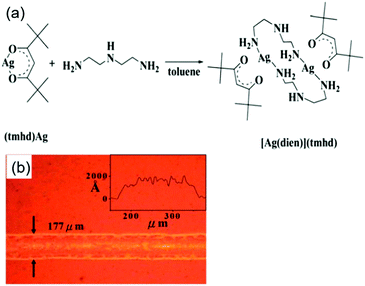 | ||
| Fig. 16 (a) The synthetic reaction of the [Ag(dien)](tmhd) complex. (b) The optical microscopy image of printed conductive silver lines on flexible PI substrates. Reproduced with permission from ref. 48. Copyright 2013, Royal Society of Chemistry. | ||
Dong et al. prepared a transparent silver ink using silver oxalate as a precursor, ethylamine as a complexing agent, ethyl alcohol and ethylene glycol as the solvent.51 The ink had fairly good stability and remained colourless and transparent without any precipitation after storage below 10 °C away from light for several months, as shown by the optical image in Fig. 17a. The printed patterns on a PI substrate sintered at 150 °C for 30 min showed metalized silver (Fig. 17b) with low resistivity (8.6 μΩ cm) and favorable flexibility (Fig. 17c) and good adhesion (Fig. 17d).
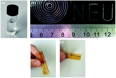 | ||
| Fig. 17 (a) Optical image of the silver oxalate ink after storage for several months; (b) photographs of the inkjet printing patterns cured at 150 °C for 30 min; (c) image of the bent patterns and (d) picture of tape test for the inkjet printing line. Reproduced with permission from ref. 51. Copyright 2015 Elsevier. | ||
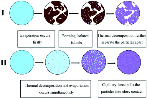
Dong et al. also formulated a particle-free silver ink by using silver tartrate as a precursor, different types of amines as the complexing agent and ethanol as the solvent.75 The research found that the amine type has a significant influence on the thermal behavior and electrical performance of the formulated inks and the morphology of the associated films with the possible mechanisms illustrated in Fig. 20. The film derived from a 1,2-diaminopropane ink showed the lowest resistance and uniform surface morphology consisting of smaller and more densely packed particles. By further optimizing the ink formula, a film resistivity of 4.3 μΩ cm was obtained at 160 °C.
Using a solid complex of silver oxalate and ethylenediamine (Fig. 18), Zope et al. also formulated a particle-free ink with 25.9% silver content for inkjet printing.99 A hybrid heat-photonic curing method was employed to improve the electrical properties and adhesion of the ink. Silver conductive traces showed a resistivity of 4.26 μΩ cm, which is 2.7 times that of bulk silver.
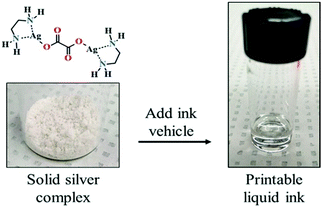 | ||
| Fig. 18 Solid silver complex that can be converted to a desired printable liquid ink. Reproduced with permission from ref. 99. Copyright 2018, American Chemical Society. | ||
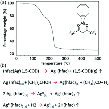
Black et al. formulated a particle-free ink based on silver hexafluoroacetylacetonate cyclooctadiene [(hfac)(1,5-COD)Ag] for the sintering-free printing of highly conductive silver films.83 An alcohol, propan-2-ol, was used as a catalytic reducing agent to dissociate the [(hfac)(1,5-COD)Ag] precursor. Silver films printed from the ink, on a glass substrate at 120 °C, showed a resistivity as low as 39.2% that of bulk silver, without sintering. Fig. 19a shows the thermogravimetric result of the pure [(hfac)(1,5-COD)Ag] ink component, and Fig. 19b shows the decomposition processes of [(hfac)(1,5-COD)Ag].
 | ||
| Fig. 19 (a) Thermogravimetric analysis of the decomposition of the pure [(hfac)(1,5-COD)Ag] ink component. (b) The decomposition processes of [(hfac)(1,5-COD)Ag]. Reproduced with permission from ref. 83. Copyright 2016, Rights Managed by Nature Publishing Group. | ||
Table 3 makes a comparison of the developed particle-free silver inks. Overall, this type of ink needs specific metal salts for its formulation and has a relatively low sintering temperature (∼150 °C) for conductivity comparable to that of bulk silver. The difficulties are to select an appropriate organic silver salt and ligand. The inks reported in ref. 45, 51, 68, 69 and 75 have facile synthesis routes, good conductivity and printability, which basically fulfilled the criteria for an optimal ink design.
| No. | Ink composition | Patterning method | Resistivity (μΩ cm) | Ref. | |||
|---|---|---|---|---|---|---|---|
| Silver precursor | Complexing agent | Solvent | Deposition | Metallization | |||
| 1 | Silver neodecanoate | None | Xylene | Ink-jet printing | 150 °C | 3–4.8 | 78 |
| 2 | Silver(I) 2-[2-(2-methoxyethoxy)ethoxy]acetate | — | DI water | Ink-jet printing | 130 °C with UV irradiation, 30 min | 9.10 | 82 |
| 3 | Silver nitrate | 1-Dimethylamino-2-propanol | Ethanol and ethylene glycol | Ink-jet printing | 100 °C for 60 min | 13.7 | 50 |
| 4 | Silver acetate | Ammonium hydroxide | Aqueous solution containing formic acid | Ink-jet printing, direct-writing and airbrush-spraying | 90 °C for 15 min | 1.6 | 45 |
| 5 | Silver acetate | Ethylamine, ethanolamine and formic acid (reducing agent) | DI water containing methanol | Ink-jet printing | 150 °C for 30 min | 4.71 (PEN substrate) | 69 |
| 6 | Silver acetate | Ethylamine and ammonia as complexing agents, formic acid as a reducing agent | HEC as a viscosifier and stabilizer, ethanolamine as an anticlogging additive | Spin-coating or Ink-jet printing | 90 °C for 24 h (Spin-coating, glass substrate); 75 °C for 60 min (Nozzle-jet printing, PET substrate) | 19.8; 36.5 | 70 |
| 7 | Silver carbonate | Isopropyl amine | Glycol and DI water | Handwriting | 150 °C for 60 min | 18 | 47 |
| 8 | Silver citrate | 1,2-Diaminopropane | Methanol and isopropanol | Ink-jet printing | 150 °C for 50 min | 17 | 71 |
| 9 | β-Diketonate silver | — | Hexylamine and ethyl cellulose solution | Ink-jet printing | 250 °C for 180 min | 4.62–9.37 | 48 |
| 10 | Silver oxalate | Ethylamine | Ethyl alcohol and ethylene glycol | Ink-jet printing | 170 °C for 30 min | 8.4 | 51 |
| 11 | Silver oxalate | Ethylenediamine | DI water | Ink-jet printing | Thermal-photonic curing: 120 °C for 5 min, 3.32 J cm−2 | 4.28 | 99 |
| 12 | Silver tartrate | 1,2-Diaminopropane | Ethanol | Ink-jet printing | 160 °C for 10 min | 4.3 | 75 |
| 13 | Silver oxide | Ammonium carbamate | Methanol | Laser direct writing | Laser power, 0.5 W | 6.5 | 67 |
| 14 | Silver oxide | Ammonium hydroxide, Diethanolamine | DI water | Ink-jet printing | 75 °C for 20 min | 6 | 68 |
| 15 | Silver hexafluoroacetylacetonate cyclooctadiene | — | Toluene and propan-2-ol | Ink-jet printing | 120 °C (substrate) | 4.1 | 83 |
4.2 Copper-based particle-free inks
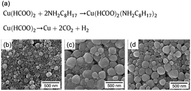
In contrast to the particle inks, copper particle-free inks are stable under an aerobic atmosphere. Thus, they have been developed in recent years. The most prominent example is copper formate due to the advantages of its clean decomposition at low temperature without any organic residues.Yabuki et al. prepared a particle-free copper ink by mixing copper(II) formate tetrahydrate, n-octyl amine and toluene.52 The copper conductive film was fabricated on a glass substrate by calcination of the ink at low temperatures in a nitrogen atmosphere, and consisted of spherical copper nanoparticles of 100–300 nm (Fig. 21b–d). The lowest resistivity of 20 μΩ cm was obtained at 140 °C for 60 min. Fig. 21 shows the chemical reactions in the ink during the synthesis and sintering processes. They also formulated particle-free copper inks via a complex of copper(II) formate and aminediol.92 The copper conductive film was produced at low temperature on a glass substrate by calcination of these inks. The effect of the aminediol type and the calcination temperature on the conductivity of the copper films was investigated. The results showed that the films calcined with the inks from 3-dimethylamino-1,2-propanediol or 3-diethylamino-1,2-propanediol had electrical conductivity at 165–180 °C, even under an air atmosphere.
 | ||
| Fig. 20 Schematic presentation of the effect of amines on microstructure evolution. Reproduced with permission from ref. 75. Copyright 2016 Elsevier. | ||
 | ||
| Fig. 21 (a) Chemical reaction in the as-prepared copper formic ink during synthesis and sintering processes; (b–d) SEM images of the copper conductive film obtained by calcination for 60 min at 110 °C, 140 °C, and 160 °C. Reproduced with permission from ref. 52. Copyright 2011 Elsevier. | ||
Kim et al. formulated particle-free copper inks by mixing copper(II) formate and hexylamine or deionized water in different weight ratios.91 They found that the concentration of copper complexes in the inks had a significant influence on the porosity and impurity content, and ultimately the electrical resistivity of the films. The lowest resistivity obtained in Cu films made from these inks was 5.2 μΩ cm.
Wang et al. designed a copper ion ink based on copper(II) hydroxide, which showed excellent ion complex stability and dispersion stability.93 The pH and complexing agent were two key factors in the ink formulation process, as shown in Fig. 22a. The formulated ink was environmentally friendly and can be written and sintered using intense pulsed light at low temperatures, showing excellent electrical properties. Fig. 22 show some patterns of one ink written by a roller-ball pen.
 | ||
| Fig. 22 (a) Colour changes of the fabricated Cu ion ink as a function of pH. (b) Patterns of the ion ink printed using a roller-ball pen. Reproduced with permission from ref. 93. Copyright 2013, American Chemical Society. | ||
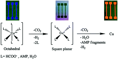
Farraj et al. reported a copper particle-free ink with the ability of self-reduction.101 The ink was composed of copper formate complexed with 2-amino-2-methyl-1-propanol, diethylene glycol methyl ether and n-butanol, generating conductive copper patterns at 140 °C in a nitrogen environment. The decomposition process of the copper complex in the ink was investigated and a mechanism was proposed (Fig. 23). The formulated ink is chemically stable in air and easy to process in inkjet printing. The lowest resistivity of the printed copper film was obtained at 190 °C, less than 10.5 μΩ cm.
 | ||
| Fig. 23 A suggested mechanism for the decomposition of the complex from an octahedral to a square planar configuration to metallic copper. An image of the obtained film at each stage is presented on top. Reproduced with permission from ref. 101. Copyright 2015, Royal Society of Chemistry. | ||
We designed a new complex oxidation–reduction process of copper acetate and cyclohexylamine together with formic acid to prepare a copper particle-free ink.55 Although the ink contained only 9.6 wt% of copper, it still offered good conductivity. The research showed that formic acid was the most important factor influencing the conductivity of the film.
Qi et al. formulated a particle-free copper ink based on a self-reducible copper hydroxide complex for the fabrication of conductive copper patterns.53 Copper hydroxide was converted to a self-reducible complex with 3-dimethylamino-1,2-propanediol to reduce the temperature for the reduction of copper ions. A small amount of formic acid was used to catalyze the self-reduction of the complex to copper. The results showed that the self-reduction temperature could be reduced to about 130 °C and the films exhibited good electrical performance after sintering at temperatures of 160, 180, and 200 °C, with a resistivity of 238 ± 32, 166 ± 21 and 139 ± 24 μΩ cm, respectively.
Xu et al. investigated the effects of water on the performance of copper complex inks with various amines as ligands. It was found that water had two effects.89 It was not ideal for the preservation of the inks but was conducive to forming a dense copper film with good conductivity. A novel ink formulation was proposed to balance the dual effects. The formulated ink with 2 wt% water could be stored for at least two months, and still yielded a highly conductive copper film at low sintering temperature.
Similarly, Table 4 makes a comparison of the currently developed copper particle-free inks. Overall, the precursors for this type of ink are very limited and most of them are based on copper(II) formate. The ink reported in ref. 101 showed a good property for ink-jet printing electronics but the sintering temperature is still high. Here, photonic sintering such as intensive pulsed light sintering shows an advantage in the effective sintering of such inks under ambient conditions within a millisecond time frame.
| No. | Ink composition | Patterning method | Resistivity (μΩ cm) | Ref. | |||
|---|---|---|---|---|---|---|---|
| Copper precursor | Complexing agent | Solvent | Deposition | Metallization | |||
| 1 | Copper(II) formate tetrahydrate | n-Octyl amine | Toluene | Squeegee coating | 140 °C for 60 min, N2 | 20 | 52 |
| 2 | Copper(II) formate tetrahydrate | 2-Amino-2-methyl-1-propanol | Isopropyl alcohol | Drop coating | 350 °C for 30 min, N2 | 9.46 | 88 |
| 3 | Copper acetate | Cyclohexylamine | Ethanol/ethylene glycol mixture | Drop coating | 230 °C for 60 min, N2 | 22 | 90 |
| 4 | Copper(II) formate hydrate | Hexylamine | — | Coating | 250 °C for 2 min with formic acid | 5.2 | 91 |
| 5 | Copper(II) formate anhydrate | 3-Dimethylamino-1,2-propanediol | — | Squeegee coating | 180 °C for 5 min | 300 | 92 |
| 6 | Copper(II) hydroxide | Formic acid and citric acid | DI water | Handwriting | Intensive pulsed light sintering | 3.21–5.27 | 93 |
| 7 | Copper(II) formate tetrahydrate | 2-Amino-2-methyl-1-propanol | Diethylene glycol methyl ether and n-butanol | Inkjet printing | 190 °C for 2 min, N2 | 10.5 | 101 |
| 8 | Copper formate/acetate/oleate | Diethanolamine | Ethanol | Inkjet printing | Intensive pulsed light sintering | 56 | 111 |
| 9 | Copper format | Hexylamine and 2-amino-2-methyl-1-propanol | Isopropyl alcohol | Spin coating | Laser sintering | 17 | 131 |
4.3 Gold-based particle-free inks
Schoner et al. reported a particle-free gold ink for inkjet printing of gold structures and lines.97 The ink was formulated by dissolving a liquid gold(I) precursor [AuO2CCH2(OCH2CH2)2OCH3(nBu3P)] in toluene. The thermal behavior of the precursor was studied, showing that the decomposition of [AuO2CCH2(OCH2CH2)2OCH3(nBu3P)] started at 230 °C and ended at 250 °C. The first step was the release of CO2 followed by elimination of PnBu3 and then the release of CxHyOz (x ≥ 3) organics. The printed features exhibited conductivities of up to 1.9 × 10⁷ S m−1 on glass which corresponds to 43% of the conductivity of bulk gold. Fig. 24 shows the chemical reaction equation for precursor synthesis. | ||
| Fig. 24 Chemical reaction equation for gold(I) precursor synthesis.97 | ||
4.4 Hybrid metal particle-free inks
As described in Section 3, copper or silver particle-free inks have been developed due to their low cost, flexibility in preparation and a relatively low-temperature sintering in comparison with the nano silver or copper-based inks. The ink of copper formate52,88,92,101,103,108,132,133 or silver oxalate51,99,106 has made significant development with their advantages over other types of metal inks. This type of ink, however, also has drawbacks. Silver particle-free ink is expensive and the resultant patterns have low resistance against electromigration, while the copper particle-free ink has low content of copper, leading to a poor electrical performance. Therefore, it will be advantageous to develop a copper–silver hybrid complex ink combining the benefits of copper and silver.Recently it has been shown that it is possible to produce metal complex-based Cu–Ag conductive inks where the catalytic activity of silver was used to accelerate the decomposition of the copper complex into pure metal particles under mild and low-temperature conditions (Fig. 25).134 We formulated new Cu–Ag hybrid inks based on the simultaneous complexation reaction of copper formate and silver oxalate with 1,2-diaminopropane.135 The process is simple, facile and only one-step.
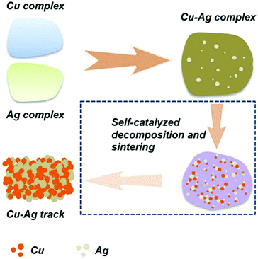 | ||
| Fig. 25 Schematic illustration of self-catalyzed decomposition and sintering of Cu–Ag complex inks. Reproduced with permission from ref. 134. Copyright 2018, Royal Society of Chemistry. | ||
5. Application
Metal particle-free ink materials have made significant progress in recent years; however, most research has focused on the ink formulation and property optimization; the applications in the field of electronic and energy devices are fewer than those with metal nano inks. Until now, most of the studies have mainly concentrated on the enhancement of conductivity and adhesion of the resultant metal silver or copper films, the decomposition mechanism of the metal–ligand complex and the effects of the ligand type on the ink properties and the morphology of the associated films. But for practical applications, such inks have great potential.5.1 Stretchable circuits
Fast fabrication of stretchable patterns or circuits is desirable and has become the focus of recent research. Towards this, Hu et al. reported a writable particle-free ink for fast fabrication of highly conductive stretchable circuits.136 The ink was composed of soluble silver trifluoroacetate, butanone and adhesive rubber (polystyrene-block-polyisoprene-block-polystyrene), which could be used to produce conductive traces by handwriting and subsequent reduction in a solution of formaldehyde and sodium hydroxide. Owing to the effect of the adhesive polymer in inks, the written traces have not only good adhesion onto the substrate but also good stretchability after drying.A heart-like circuit was fabricated in the research, showing good ability to endure various deformations, such as bending, stretching, and twisting, as shown in Fig. 26.
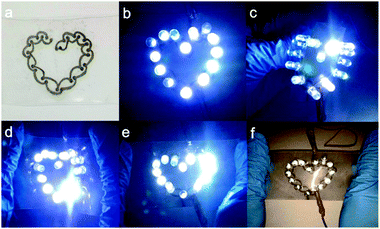 | ||
| Fig. 26 (a) Heart-like circuit drawn by a ballpoint pen; (b) 14 LED lights were lit to show a regular heart shape; LED lights can still work under different deformations; (c) outward bending; (d) inward bending; (e) stretching; and (f) flash photograph under stretching. Reproduced with permission from ref. 136. Copyright 2016, American Chemical Society. | ||
5.2 Solar cells
Tamari et al. formulated a lead and particle free metal hybrid ink for the front side metallization of silicon solar cells.137 The ink was composed of 26% metal including silver-, bismuth-, and zinc neodecanoate, which can etch locally through the silicon nitride antireflection layer and form contact to the emitter after curing at 480 °C for 5 min. The bismuth and zinc components were responsible for etching the silicon nitride layer. Xylol and N-methyl-2-pyrrolidone were chosen as the ink solvents to dissolve silver neodecanoate and to obtain good printing results.5.3 Radio frequency inductors
Vaseem et al. fabricated spiral RF inductors by ink-jet printing silver particle-free inks.69 The inductors were fabricated on PET substrates using five layers of silver ink with a Dimatix inkjet printer. A universal laser system was employed to cut via holes and make a connection with the underside of the inductors. A depiction of the dimensions of the inductors and an image of the printed inductor are shown in Fig. 27. The inductors were measured in a two-port configuration using 500 μm pitch Z-probes and a cascade probe station. Inductance values of up to 35 nH with quality factors greater than 10 at frequencies above 1.5 GHz proved the viability of the ink for fabrication of printed electronics.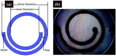 | ||
| Fig. 27 (a) Depiction of the inductor with dimensions. (b) Microscopy image of a printed inductor. Reproduced with permission from ref. 69. Copyright 2016, American Chemical Society. | ||
5.4 Other applications
Sensors can detect changes in their environment, which allows people or robots to make a correct response efficiently. Printed flexible sensors have many advantages such as lightweight, bendability, and foldability as well as low cost.3 Metal particle-free inks can be used to fabricate sensors for medication control, gas detection, drug delivery and food traceability. High silver content is the best for general glucose sensor applications while low ratios are best suited for Iontophoretic applications (a non-invasive technique where a small electric current is used to deliver drugs through the skin) due to the specific electrochemical requirements of those cells.138Smart tags, membrane touch switches, battery patches and electro-chromatic displays can also be produced using such inks; however, cases are very rare at present.
6. Summary and outlook
As summarized above, remarkable progress has been achieved in the development of metal particle-free inks. For silver-based particle free inks, there are many types available. Most of them have better stability and good conductivity after low-temperature treatment (150 °C), allowing the inks to be used for inkjet-printing technology and a variety of flexible substrates. However, the high cost of silver is a problem, which limits the wide application of such inks.The properties of silver-based particle-free inks, such as stability, thermal behaviour and electrical performance, vary primarily with the type of silver salt and the ligand selected to solubilize it. The key points in formulating stable inks with controlled microstructures are to select appropriate organic silver salts and ligands. Therefore, silver precursors with desirable thermal and electrical properties are necessary for future development of particle free inks with improved performance. New metal salt precursors or metal complexes with high solubility and low decomposition temperature are a direction for further research.
Printability is also an issue to be solved when using these inks to produce patterns with high resolution. The fluidic properties of the as-prepared silver inks, such as viscosity, surface tension and wettability, should be specifically adjusted, and the printing parameters should be carefully controlled in order to obtain good printing quality.
In terms of copper particle-free inks, they are cheap in cost as compared to silver particle-free inks. However, the precursors available for selection are very limited and most of them are based on copper(II) formate. New precursors should be exploited. Besides, the copper content in the inks is low, usually below 20%, which could only produce very thin copper films or patterns unless multi-printing is carried out. Moreover, at present, most copper particle-free inks require reductive atmospheres (such as hydrogen gas or formic gas) or a special sintering method (intense pulsed light or laser) to make the printed tracks conductive, which have safety and cost issues. In some cases, the ink has a compatibility problem with mass production techniques. Towards these problems, ink materials and sintering technologies need to be explored for energy-efficient manufacturing of flexible electronics. In this respect, self-sintering, where sintering occurs spontaneously in the patterning process, is preferred. A Cu–Ag hybrid particle-free ink is also a good choice for low-temperature fabrication of conductive patterns which not only can reduce the cost of silver ink but also can accelerate the sintering of the copper ink under reduced temperature conditions.
The silver or copper particle-free inks have great application potential in the fields of electronics and energy devices. However, so far there have been only a few examples. Therefore, it will be advantageous to exploit the possibilities of such inks in the area of electronic and energy devices.
Conflicts of interest
All authors declare that they have no conflicts of interest.Acknowledgements
The authors acknowledge the funding by the German Federal Ministry of Education and Research (BMBF), the Helmholtz Energy Materials Foundry (HEMF) and PEROSEED (ZT-0024) project. This work was carried out in the framework of the Joint Lab GEN_FAB. All copyright holders are also gratefully acknowledged for granting permission for the use of figures, such as RSC, ACS, IOP, Elsevier and Nature Publishing Group.References
- T. S. Tran, N. K. Dutta and N. R. Choudhury, Adv. Colloid Interface Sci., 2018, 261, 41–61 CrossRef CAS PubMed.
- Z. Yin, Y. Huang, N. Bu, X. Wang and Y. Xiong, Chin. Sci. Bull., 2010, 55, 3383–3407 CrossRef.
- W. Li, Doctoral dissertation, Osaka University, 2018.
- M. A. Leenen, V. Arning, H. Thiem, J. Steiger and R. Anselmann, Phys. Status Solidi A, 2009, 206, 588–597 CrossRef CAS.
- D.-Y. Wang, Y. Chang, Y.-X. Wang, Q. Zhang and Z.-G. Yang, Mater. Technol., 2016, 31, 32–37 CrossRef CAS.
- A. M. Jeffries, A. Mamidanna, L. Ding, O. J. Hildreth and M. I. Bertoni, IEEE J. Photovolt., 2016, 7, 37–43 Search PubMed.
- R. Dang, L. Song, W. Dong, C. Li, X. Zhang, G. Wang and X. Chen, ACS Appl. Mater. Interfaces, 2013, 6, 622–629 CrossRef PubMed.
- M. Dankoco, G. Tesfay, E. Bènevent and M. Bendahan, Mater. Sci. Eng., B, 2016, 205, 1–5 CrossRef CAS.
- D. Lupo, W. Clemens, S. Breitung and K. Hecker, Applications of Organic and Printed Electronics, Springer, 2013, pp. 1–26 Search PubMed.
- K. Suganuma, Introduction to printed electronics, Springer Science & Business Media, 2014 Search PubMed.
- N. Perinka, C. H. Kim, M. Kaplanova and Y. Bonnassieux, Phys. Procedia, 2013, 44, 120–129 CrossRef CAS.
- R. Brooke, D. Evans, M. Dienel, P. Hojati-Talemi, P. Murphy and M. Fabretto, J. Mater. Chem. C, 2013, 1, 3353–3358 RSC.
- T. Gomes, C. Constantino, E. Lopes, A. E. Job and N. Alves, Thin Solid Films, 2012, 520, 7200–7204 CrossRef CAS.
- Y. Liao, R. Zhang, H. Wang, S. Ye, Y. Zhou, T. Ma, J. Zhu, L. D. Pfefferle and J. Qian, RSC Adv., 2019, 9, 15184–15189 RSC.
- W. R. Small and M. in het Panhuis, Small, 2007, 3, 1500–1503 CrossRef CAS PubMed.
- J.-W. Han, B. Kim, J. Li and M. Meyyappan, Mater. Res. Bull., 2014, 50, 249–253 CrossRef CAS.
- K. Kordás, T. Mustonen, G. Tóth, H. Jantunen, M. Lajunen, C. Soldano, S. Talapatra, S. Kar, R. Vajtai and P. M. Ajayan, Small, 2006, 2, 1021–1025 CrossRef PubMed.
- J. Zhao, Y. Gao, J. Lin, Z. Chen and Z. Cui, J. Mater. Chem., 2012, 22, 2051–2056 RSC.
- L. Huang, Y. Huang, J. Liang, X. Wan and Y. Chen, Nano Res., 2011, 4, 675–684 CrossRef CAS.
- A. Al Shboul, C. Trudeau, S. Cloutier, M. Siaj and J. Claverie, Nanoscale, 2017, 9, 9893–9901 RSC.
- W. Yang and C. Wang, J. Mater. Chem. C, 2016, 4, 7193–7207 RSC.
- S. H. Chae and Y. H. Lee, Nano Convergence, 2014, 1, 15 CrossRef PubMed.
- Y. Gao, W. Shi, W. Wang, Y. Leng and Y. Zhao, Ind. Eng. Chem. Res., 2014, 53, 16777–16784 CrossRef CAS.
- K. Arapov, R. Abbel and H. Friedrich, Faraday Discuss., 2014, 173, 323–336 RSC.
- X. Han, Y. Chen, H. Zhu, C. Preston, J. Wan, Z. Fang and L. Hu, Nanotechnology, 2013, 24, 205304 CrossRef CAS PubMed.
- F. Torrisi, T. Hasan, W. Wu, Z. Sun, A. Lombardo, T. S. Kulmala, G.-W. Hsieh, S. Jung, F. Bonaccorso and P. J. Paul, ACS Nano, 2012, 6, 2992–3006 CrossRef CAS PubMed.
- C.-L. Lee, C.-H. Chen and C.-W. Chen, Chem. Eng. J., 2013, 230, 296–302 CrossRef CAS.
- S. Majee, C. Liu, B. Wu, S.-L. Zhang and Z.-B. Zhang, Carbon, 2017, 114, 77–83 CrossRef CAS.
- C. N. Chen, C. P. Chen, T. Y. Dong, T. C. Chang, M. C. Chen, H. T. Chen and I. G. Chen, Acta Mater., 2012, 60, 5914–5924 CrossRef CAS.
- S. Magdassi, M. Grouchko, O. Berezin and A. Kamyshny, ACS Nano, 2010, 4, 1943–1948 CrossRef CAS PubMed.
- S. Jeong, H. C. Song, W. W. Lee, Y. Choi, S. S. Lee and B.-H. Ryu, J. Phys. Chem. C, 2010, 114, 22277–22283 CrossRef CAS.
- R. Shankar, L. Groven, A. Amert, K. W. Whites and J. J. Kellar, J. Mater. Chem., 2011, 21, 10871–10877 RSC.
- Y. Lee, J.-r. Choi, K. J. Lee, N. E. Stott and D. Kim, Nanotechnology, 2008, 19, 415604 CrossRef PubMed.
- B. K. Park, D. Kim, S. Jeong, J. Moon and J. S. Kim, Thin Solid Films, 2007, 515, 7706–7711 CrossRef CAS.
- S. Jeong, S. H. Lee, Y. Jo, S. S. Lee, Y.-H. Seo, B. W. Ahn, G. Kim, G.-E. Jang, J.-U. Park and B.-H. Ryu, J. Mater. Chem. C, 2013, 1, 2704–2710 RSC.
- J. S. Kang, H. S. Kim, J. Ryu, H. T. Hahn, S. Jang and J. W. Joung, J. Mater. Sci.: Mater. Electron., 2010, 21, 1213–1220 CrossRef CAS.
- D. Deng, Y. Jin, Y. Cheng, T. Qi and F. Xiao, ACS Appl. Mater. Interfaces, 2013, 5, 3839–3846 CrossRef CAS PubMed.
- Y. Hokita, M. Kanzaki, T. Sugiyama, R. Arakawa and H. Kawasaki, ACS Appl. Mater. Interfaces, 2015, 7, 19382–19389 CrossRef CAS PubMed.
- Q. Huang, W. Shen, Q. Xu, R. Tan and W. Song, Mater. Chem. Phys., 2014, 147, 550–556 CrossRef CAS.
- A. Kosmala, R. Wright, Q. Zhang and P. Kirby, Mater. Chem. Phys., 2011, 129, 1075–1080 CrossRef CAS.
- B. Lee, Y. Kim, S. Yang, I. Jeong and J. Moon, Curr. Appl. Phys., 2009, 9, e157–e160 CrossRef.
- R.-Z. Li, A. Hu, T. Zhang and K. D. Oakes, ACS Appl. Mater. Interfaces, 2014, 6, 21721–21729 CrossRef CAS PubMed.
- J.-T. Wu, S. L.-C. Hsu, M.-H. Tsai, Y.-F. Liu and W.-S. Hwang, J. Mater. Chem., 2012, 22, 15599–15605 RSC.
- N. N. Jason, W. Shen and W. Cheng, ACS Appl. Mater. Interfaces, 2015, 7, 16760–16766 CrossRef CAS PubMed.
- S. B. Walker and J. A. Lewis, J. Am. Chem. Soc., 2012, 134, 1419–1421 CrossRef CAS PubMed.
- W.-d. Yang, C.-y. Liu, Z.-y. Zhang, Y. Liu and S.-d. Nie, J. Mater. Chem., 2012, 22, 23012–23016 RSC.
- Y. Chang, D.-Y. Wang, Y.-L. Tai and Z.-G. Yang, J. Mater. Chem., 2012, 22, 25296–25301 RSC.
- C.-N. Chen, T.-Y. Dong, T.-C. Chang, M.-C. Chen, H.-L. Tsai and W.-S. Hwang, J. Mater. Chem. C, 2013, 1, 5161–5168 RSC.
- Y. Mou, H. Cheng, H. Wang, Q. Sun, J. Liu, Y. Peng and M. Chen, Appl. Surf. Sci., 2019, 475, 75–82 CrossRef CAS.
- J.-T. Wu, S. L.-C. Hsu, M.-H. Tsai and W.-S. Hwang, J. Phys. Chem. C, 2011, 115, 10940–10945 CrossRef CAS.
- Y. Dong, X. Li, S. Liu, Q. Zhu, J.-G. Li and X. Sun, Thin Solid Films, 2015, 589, 381–387 CrossRef CAS.
- A. Yabuki, N. Arriffin and M. Yanase, Thin Solid Films, 2011, 519, 6530–6533 CrossRef CAS.
- T. Qi, Z. Zhang, Y. Li, J. Wang and F. Xiao, J. Mater. Chem. C, 2018, 6, 11320–11327 RSC.
- D. Deng, T. Qi, Y. Cheng, Y. Jin and F. Xiao, J. Mater. Sci.: Mater. Electron., 2014, 25, 390–397 CrossRef CAS.
- W.-d. Yang, C.-y. Liu, Z.-y. Zhang, Y. Liu and S.-d. Nie, RSC Adv., 2014, 4, 60144–60147 RSC.
- D. Adner, F. M. Wolf, S. Möckel, J. Perelaer, U. S. Schubert and H. Lang, Thin Solid Films, 2014, 565, 143–148 CrossRef CAS.
- A. Kamyshny, J. Steinke and S. Magdassi, Open Appl. Phys. J., 2011, 4, 19–36 CrossRef CAS.
- P. Karthik and S. P. Singh, RSC Adv., 2015, 5, 77760–77790 RSC.
- C. Y. Lai, C. F. Cheong, J. S. Mandeep, H. B. Abdullah, N. Amin and K. W. Lai, J. Mater. Eng. Perform., 2014, 23, 3541–3550 CrossRef CAS.
- P. Karthik and S. P. Singh, RSC Adv., 2015, 5, 63985–64030 RSC.
- A. Kamyshny and S. Magdassi, Small, 2014, 10, 3515–3535 CrossRef CAS PubMed.
- N. Uvarov, L. Burleva, M. Mizen, D. Whitcomb and C. Zou, Solid State Ionics, 1998, 107, 31–40 CrossRef CAS.
- R. Szczęsny and E. Szłyk, J. Therm. Anal. Calorim., 2013, 111, 1325–1330 CrossRef.
- N. M. Reinartz, US Pat., 11/295919, 2006 Search PubMed.
- Q. Huang, W. Shen and W. Song, Appl. Surf. Sci., 2012, 258, 7384–7388 CrossRef CAS.
- S. Uttiya, C. Bernini, M. Vignolo, I. Pallecchi, D. Marré, A. S. Siri and L. Pellegrino, Thin Solid Films, 2017, 642, 370–376 CrossRef CAS.
- Z. Cai, X. Zeng and J. Liu, J. Electron. Mater., 2011, 40, 301–305 CrossRef CAS.
- S.-P. Chen, Z.-K. Kao, J.-L. Lin and Y.-C. Liao, ACS Appl. Mater. Interfaces, 2012, 4, 7064–7068 CrossRef CAS PubMed.
- M. Vaseem, G. McKerricher and A. Shamim, ACS Appl. Mater. Interfaces, 2016, 8, 177–186 CrossRef CAS PubMed.
- K. S. Bhat, R. Ahmad, Y. Wang and Y.-B. Hahn, J. Mater. Chem. C, 2016, 4, 8522–8527 RSC.
- X. Nie, H. Wang and J. Zou, Appl. Surf. Sci., 2012, 261, 554–560 CrossRef CAS.
- J.-j. Chen, J. Zhang, Y. Wang, Y.-l. Guo and Z.-s. Feng, J. Mater. Chem. C, 2016, 4, 10494–10499 RSC.
- W. Yang, C. Wang and V. Arrighi, J. Mater. Sci.: Mater. Electron., 2018, 29, 2771–2783 CrossRef CAS.
- Y. Gu, A. Wu and J. F. Federici, Thin Solid Films, 2017, 636, 397–402 CrossRef CAS.
- Y. Dong, X. Li, S. Liu, Q. Zhu, M. Zhang, J.-G. Li and X. Sun, Thin Solid Films, 2016, 616, 635–642 CrossRef CAS.
- T. Inui, R. Mandamparambil, T. Araki, R. Abbel, H. Koga, M. Nogi and K. Suganuma, RSC Adv., 2015, 5, 77942–77947 RSC.
- M. Kawazome, K. Keun-Soo and K. Suganuma, IEEE Nano, 2009, 4–6 CAS.
- A. L. Dearden, P. J. Smith, D. Y. Shin, N. Reis, B. Derby and P. O'Brien, Macromol. Rapid Commun., 2005, 26, 315–318 CrossRef CAS.
- J. J. Valeton, K. Hermans, C. W. Bastiaansen, D. J. Broer, J. Perelaer, U. S. Schubert, G. P. Crawford and P. J. Smith, J. Mater. Chem., 2010, 20, 543–546 RSC.
- A. J. Kell, C. Paquet, O. Mozenson, I. Djavani-Tabrizi, B. Deore, X. Liu, G. P. Lopinski, R. James, K. Hettak and J. Shaker, ACS Appl. Mater. Interfaces, 2017, 9, 17226–17237 CrossRef CAS.
- J. J. P. Valeton, K. Hermans, C. W. M. Bastiaansen, D. J. Broer, J. Perelaer, U. S. Schubert, G. P. Crawford and P. J. Smith, J. Mater. Chem., 2009, 20, 543–546 RSC.
- S. F. Jahn, T. Blaudeck, R. R. Baumann, A. Jakob, P. Ecorchard, T. Rüffer, H. Lang and P. Schmidt, Chem. Mater., 2010, 22, 3067–3071 CrossRef CAS.
- K. Black, J. Singh, D. Mehta, S. Sung, C. J. Sutcliffe and P. R. Chalker, Sci. Rep., 2016, 6, 20814 CrossRef CAS PubMed.
- K. Zope, Master dissertation, Rochester Institute of Technology, 2017.
- M. Lamoth, M. Plodinec, L. Scharfenberg, S. Wrabetz, F. Girgsdies, T. Jones, F. Rosowski, R. Horn, R. Schlögl and E. Frei, ACS Appl. Nano Mater., 2019, 2, 2909–2920 CrossRef CAS.
- N. Koga, S. Yamada and T. Kimura, J. Phys. Chem. C, 2012, 117, 326–336 CrossRef.
- J. Allen, Aust. J. Chem., 1960, 13, 431–442 CrossRef CAS.
- D.-H. Shin, S. Woo, H. Yem, M. Cha, S. Cho, M. Kang, S. Jeong, Y. Kim, K. Kang and Y. Piao, ACS Appl. Mater. Interfaces, 2014, 6, 3312–3319 CrossRef CAS PubMed.
- W. Xu, X. Dai, T. Zhang and T. Wang, Chem. Eng. Sci., 2018, 190, 40–47 CrossRef CAS.
- W.-d. Yang, C.-h. Wang, V. Arrighi, C.-y. Liu and D. Watson, J. Mater. Sci.: Mater. Electron., 2015, 26, 8973–8982 CrossRef CAS.
- S. J. Kim, J. Lee, Y.-H. Choi, D.-H. Yeon and Y. Byun, Thin Solid Films, 2012, 520, 2731–2734 CrossRef CAS.
- A. Yabuki, Y. Tachibana and I. W. Fathona, Mater. Chem. Phys., 2014, 148, 299–304 CrossRef CAS.
- B.-Y. Wang, T.-H. Yoo, Y.-W. Song, D.-S. Lim and Y.-J. Oh, ACS Appl. Mater. Interfaces, 2013, 5, 4113–4119 CrossRef CAS PubMed.
- C. Paquet, T. Lacelle, B. Deore, A. Kell, X. Liu, I. Korobkov and P. Malenfant, Chem. Commun., 2016, 52, 2605–2608 RSC.
- M. A. Mohamed, A. K. Galwey and S. A. Halawy, Thermochim. Acta, 2004, 411, 13–20 CrossRef CAS.
- Z. Lin, D. Han and S. Li, J. Therm. Anal. Calorim., 2012, 107, 471–475 CrossRef CAS.
- C. Schoner, A. Tuchscherer, T. Blaudeck, S. F. Jahn, R. R. Baumann and H. Lang, Thin Solid Films, 2013, 531, 147–151 CrossRef CAS.
- G. Hu, J. Kang, L. W. T. Ng, X. Zhu, R. C. T. Howe, C. G. Jones, M. C. Hersam and T. Hasan, Chem. Soc. Rev., 2018, 47, 3265–3300 RSC.
- K. R. Zope, D. Cormier and S. A. Williams, ACS Appl. Mater. Interfaces, 2018, 10, 3830–3837 CrossRef CAS PubMed.
- S. Y. Heo, S. S. Park, S. J. Han and H. M. Jang, Eur. Pat., PCT/KR2007/002533, 2007 Search PubMed.
- Y. Farraj, M. Grouchko and S. Magdassi, Chem. Commun., 2015, 51, 1587–1590 RSC.
- W. Yang, C. Wang and V. Arrighi, J. Mater. Sci.: Mater. Electron., 2018, 29, 20895–20906 CrossRef CAS.
- C. Paquet, T. Lacelle, X. Liu, B. Deore, A. J. Kell, S. Lafreniere and P. R. L. Malenfant, Nanoscale, 2018, 10, 6911–6921 RSC.
- M. Vaseem, G. McKerricher and A. Shamim, ACS Appl. Mater. Interfaces, 2015, 8, 177–186 CrossRef PubMed.
- D. Wang, Y. Chang, Q. Lu and Z. Yang, Mater. Technol., 2015, 30, 54–59 CrossRef CAS.
- W. Yang, C. Wang and V. Arrighi, J. Electron. Mater., 2018, 47, 2824–2835 CrossRef CAS.
- W. Xu and T. Wang, Langmuir, 2016, 33, 82–90 CrossRef PubMed.
- A. Yabuki and S. Tanaka, Mater. Res. Bull., 2012, 47, 4107–4111 CrossRef CAS.
- Y. Dong, Z. Lin, X. Li, Q. Zhu, J.-G. Li and X. Sun, J. Mater. Chem. C, 2018, 6, 6406–6415 RSC.
- Y. Tao, Y. Tao, B. Wang, L. Wang and Y. Tai, Nanoscale Res. Lett., 2013, 8, 296 CrossRef PubMed.
- T. Araki, T. Sugahara, J. Jiu, S. Nagao, M. Nogi, H. Koga, H. Uchida, K. Shinozaki and K. Suganuma, Langmuir, 2013, 29, 11192–11197 CrossRef CAS PubMed.
- J. Mei, Doctoral dissertation, University of Pittsburgh, 2005.
- P. J. Smith and D. H. Shin, Inkjet-based micromanufacturing, John Wiley & Sons, 2012 Search PubMed.
- M. Shlomo, The chemistry of inkjet inks, World Scientific, 2009 Search PubMed.
- W. Clemens, D. Lupo, K. Hecker and S. Breitung, Organic Electronics Association (OE-A), 2011 Search PubMed.
- S.-P. Chen, H.-L. Chiu, P.-H. Wang and Y.-C. Liao, ECS J. Solid State Sci. Technol., 2015, 4, P3026–P3033 CrossRef CAS.
- J. Li, M.-C. Lemme and M. Östling, ChemPhysChem, 2014, 15, 3427–3434 CrossRef CAS PubMed.
- A. Klug, P. Patter, K. Popovic, A. Blümel, S. Sax, M. Lenz, O. Glushko, M. J. Cordill and E. J. List-Kratochvil, Proc. SPIE, 2015, 9569, 95690N CrossRef.
- M. Smith, Y. S. Choi, C. Boughey and S. Kar-Narayan, Flexible Printed Electron., 2017, 2, 015004 CrossRef.
- M. T. Rahman, J. McCloy, C. Ramana and R. Panat, J. Appl. Phys., 2016, 120, 075305 CrossRef.
- B. Y. Ahn, D. J. Lorang and J. A. Lewis, Nanoscale, 2011, 3, 2700–2702 RSC.
- Q. Mu, C. K. Dunn, L. Wang, M. L. Dunn, H. J. Qi and T. Wang, Smart Mater. Struct., 2017, 26, 045008 CrossRef.
- S. Walker, Doctoral dissertation, University of Illinois at Urbana-Champaign, 2013.
- F. C. Krebs, Sol. Energy Mater. Sol. Cells, 2009, 93, 394–412 CrossRef CAS.
- X. Wang and J. Liu, Micromachines, 2016, 7, 206 CrossRef PubMed.
- F. Mathies, E. J. List-Kratochvil and E. L. Unger, Energy Technol., 2019 DOI:10.1002/ente.201900991.
- G. Cummins and M. P. Desmulliez, Circuit World, 2012, 38, 193–213 CrossRef CAS.
- S. Wünscher, R. Abbel, J. Perelaer and U. S. Schubert, J. Mater. Chem. C, 2014, 2, 10232–10261 RSC.
- W. Li, Q. Sun, L. Li, J. Jiu, X.-Y. Liu, M. Kanehara, T. Minari and K. Suganuma, Appl. Mater. Today, 2019, 100451 CrossRef.
- M. Vaseem, S.-K. Lee, J.-G. Kim and Y.-B. Hahn, Chem. Eng. J., 2016, 306, 796–805 CrossRef CAS.
- J. Lee, B. Lee, S. Jeong, Y. Kim and M. Lee, Appl. Surf. Sci., 2014, 307, 42–45 CrossRef CAS.
- Y.-H. Choi and S.-H. Hong, Langmuir, 2015, 31, 8101–8110 CrossRef CAS PubMed.
- S. Cho, Z. Yin, Y.-K. Ahn, Y. Piao, J. Yoo and Y. S. Kim, J. Mater. Chem. C, 2016, 4, 10740–10746 RSC.
- W. Li, C.-F. Li, F. Lang, J. Jiu, M. Ueshima, H. Wang, Z.-Q. Liu and K. Suganuma, Nanoscale, 2018, 10, 5254–5263 RSC.
- W. Yang, C. Wang and V. Arrighi, J. Mater. Sci.: Mater. Electron., 2019, 30, 11607 CrossRef CAS.
- M. Hu, X. Cai, Q. Guo, B. Bian, T. Zhang and J. Yang, ACS Nano, 2015, 10, 396–404 CrossRef PubMed.
- Y. Tamari, A. Gautrein, C. Schmiga, S. Binder, M. Glatthaar and S. W. Glunz, Energy Procedia, 2014, 55, 708–714 CrossRef CAS.
- S. E. Gordon, J. R. Dorfman, D. Kirk and K. Adams, DuPont Microcircuit Materials, 2011 Search PubMed.
| This journal is © The Royal Society of Chemistry 2019 |


