Recent advances in developing high-performance nanostructured electrocatalysts based on 3d transition metal elements
Hao
Wan
abc,
Xiaohe
Liu
 *b,
Haidong
Wang
c,
Renzhi
Ma
 *a and
Takayoshi
Sasaki
 *a
*a
aInternational Center for Materials Nanoarchitectonics (WPI-MANA), National Institute for Materials Science (NIMS), Namiki 1-1, Tsukuba, Ibaraki 305-0044, Japan. E-mail: MA.Renzhi@nims.go.jp; SASAKI.Takayoshi@nims.go.jp
bState Key Laboratory of Powder Metallurgy and School of Materials Science and Engineering, Central South University, Changsha, Hunan 410083, P. R. China. E-mail: liuxh@csu.edu.cn
cSchool of Minerals Processing and Bioengineering, Central South University, Changsha, Hunan 410083, P. R. China
First published on 14th February 2019
Abstract
Electrocatalysis for clean energy conversion, including water splitting (hydrogen and oxygen evolution) and oxygen reduction, has been considered as a pivotal strategy to alleviate the increasing energy crisis and environmental pollution derived from the overuse of nonrenewable fossil fuels. Since the current electrocatalysts are usually based on high-cost and scarce noble metal elements (Pt, Ru, and Ir), developing low-cost and earth-abundant catalysts is of great practical promise for realizing industry-scale applications. In this regard, electrocatalysts based on 3d transition metal elements (Mn, Fe, Co, and Ni, etc.) have been proposed as a class of prospective materials due to their abundance and high activity. In this work, recent advances in developing high-performance nanostructured electrocatalysts for sustainable clean energy conversion are briefly reviewed, with a particular focus on morphology design, composition tuning, surface engineering and metal coordination symmetry/geometry control. The latest studies indicate that carefully designed nanostructures based on 3d transition metal elements can attain comparable electrocatalytic performance to the commercial noble metal-based counterparts. This review may offer new insights into the rational design of nanostructures with further improved electrocatalytic activity and pathway selectivity to achieve the ultimate goal of realizing renewable electrochemical energy conversion.
1. Introduction
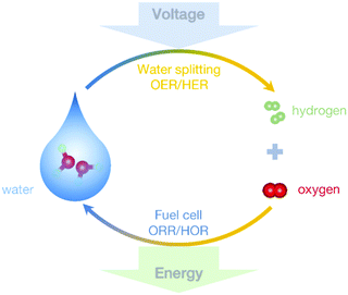
Currently, ∼80% of global energy consumption relies on traditional fossil fuels.1 With further globalization and industrialization, energy demand will continue to increase remarkably. Since the overuse of fossil fuels will not only accelerate the exhaustion of the nonrenewable energy resources, but also cause some serious environmental issues or even climate change, developing alternative, sustainable and clean energy storage and conversion systems is becoming increasingly imperative. Renewable hydrogen (H2) has been greatly valued for its high energy density and clean combustion.2 Compared to the conventional thermochemical generation of renewable H2 product, electrochemical conversion can be realized under ambient conditions by using renewable electricity energy resources.3,4 Despite the remarkable advantages, there still exist immense technological challenges in realizing commercially reliable electrochemical energy conversion processes. The electrochemical generation of H2 gas originates mainly from overall water splitting (2H2O → 2H2 + O2), as indicated in Fig. 1. However, it is usually hindered by the other kinetically slow half process, i.e., the oxygen evolution reaction (OER, 2H2O → 4H+ + O2 + 4e− for acid electrolytes while 4OH− → 2H2O + O2 + 4e− for alkaline systems), due to the multiple-proton-coupled electron transfer.5 Likewise, the efficient use of H2, such as in fuel cell devices, is restricted by the reversible process of the OER, i.e., the oxygen reduction reaction (ORR, O2 + 4H+ + 4e− → 2H2O or O2 + 2H2O + 4e− → 4OH− for a direct four-electron pathway in acidic or basic electrolytic solution, respectively).6 In addition, electrocatalysts used to accelerate these slow processes severely rely on high-cost and scarce noble metal-based materials, such as Pt for both HER and ORR, and IrO2 and/or RuO2 for OER.7–9 To achieve large-scale conversion of renewable energy resources, development of efficient and low-cost electrocatalysts to replace noble metal-based materials is urgently needed.Compounds based on 3d transition metals (TMs, such as Mn, Fe, Co and Ni) constitute a typical class of non-precious metal-based materials. Due to the unique electronic configurations ([Ar]3d5–84s2), they show facile redoxable properties and have been widely used in supercapacitors, batteries, sensors, etc.10–13 Furthermore, in the past decade, various kinds of TM-based materials, including pure metals, alloys, carbides, nitrides, bismuthides, chalcogenides, phosphides, oxides, hydroxides and/or their composites, have also been investigated for use as electrocatalysts.14–18 Although these TM-based catalysts have shown catalytic performance superior to that of non-TM-based materials (e.g. carbon) and even comparable to that of noble metal-based benchmarks, considerable challenges and issues still need to be addressed. Therefore, exploiting TM-based electrocatalyst candidates with high activity and selectivity remains a rigorous challenge.
There are some excellent reviews on electrocatalysts for highly efficient electrocatalysis. However, they mainly focus on metal-free nanostructures,19 materials based on specific species (e.g. oxides or dichalcogenides)20–22 or particular electrocatalytic processes (such as the OER).23,24 Few of them have paid sufficient attention to the versatile strategies for improving the activity of electrocatalysts. To achieve the high performance for industrial use, it is therefore indispensable to systematically survey newly emerging advances which will bring new methodologies.
Typically, two strategies are widely adopted for improving the performance of electrocatalysts.25 (i) The first approach is to expose more accessible active sites for catalytic reactions. (ii) The second way is to enhance the intrinsic reactivity of each active site. In practice, these two strategies are not mutually independent; sometimes, they can be applied simultaneously.
In this respect, we review several typical case investigations on recent advances in improving the electrocatalytic OER, HER and/or ORR performance of TM-based electrocatalysts, e.g., morphology design, composition tuning, surface engineering and metal coordination control. The versatile methodologies and rationales of 3d TM-based materials reviewed in this article may also be applicable for the fundamental investigations and practical uses of other precious metal-free electrocatalysts.
2. Electrocatalytic activity order of 3d TM-based compounds
For TM-based compounds, metal centers usually act as electrocatalytic active sites. Taking single-metal TM2+δOδ(OH)2−δ (0 ≤ δ ≤ 1.5) as an example, in the OER region, δ = 1 represents MOOH (e.g. CoOOH). As can be seen from Fig. 2a, the higher overpotential to achieve a current density of 5 mA cm−2 indicates the lower OER activity, revealing the weaker adsorbed OH (denoted as OHad)-Pt interaction. Compared with bare Pt, the Pt electrode decorated by CoOOH exhibited obvious activity enhancement, which was ascribed to the enhanced interaction of OH− with CoOOH. The OER polarization curve of the CoOOH/Au electrode, almost overlapping that of CoOOH/Pt as depicted in the inset of Fig. 2a, further confirmed that the electrocatalytic activity is influenced by the interaction of OH− with TM2+δOδ(OH)2−δ. When this interaction is weak, the formation of OHad–TM2+δOδ(OH)2−δ, i.e. OH− + TM2+δOδ(OH)2−δ ↔ OHad–TM2+δOδ(OH)2−δ + e−, is the rate-determining step. In contrast, too strong interaction between TM2+δOδ(OH)2−δ and OHad can result in an adverse effect since the intermediates are stabilized, “poisoning” the surface of the electrocatalyst and decreasing the OER activity. Due to the different 3d electron configurations, OH–TM2+δ bond strength varies along with the TM species, resulting in an electrocatalytic activity order for the 3d TM hydro(oxy)oxide systems of Ni > Co > Fe > Mn for OER.26 Similar OER reactivity orders, related to the species of the TM active sites, can also be observed for metals and their oxides, phosphates, phosphides, etc.27–29 In addition, some TM-based materials have also been developed for electrocatalytic water reduction processes. Fig. 2b displays the polarization curves of TM selenides for the electrocatalytic HER.30 Generally, the HER proceeds in 2 steps: a Volmer reaction (H3O+ + e− → Had + H2O, herein Had represents adsorbed H on the surface of the catalyst) followed by a recombination step (i.e. Tafel reaction, 2Had → H2) or the Heyrovsky reaction (Had + H3O+ + e− → H2 + H2O). The kinetics are mainly determined by the interaction strength of Had-electrocatalysts. The change in TM species may influence the activity. For instance, CoSe2 and NiSe2 showed analogous HER activity, superior to the FeSe2 material. ORR is considered as the reverse process of OER. The activity is also determined by the interaction between electrocatalysts and reactant/intermediates and therefore varies along with the TM species. As shown in Fig. 2c and d, ORR polarization curves of the TM carbides, obtained in 0.1 M KOH, are similar to that of the commercial Pt/C material.31 For Fe3C, Co3C and Ni3C, the electron transfer numbers, calculated from the Koutecky–Levich plots, were close to 4, indicating a four-electron reduction pathway. The half-wave potential (E1/2) is 0.78 V vs. the reversible hydrogen electrode (RHE) for Fe3C and 0.77 V for both Co3C and Ni3C. In particular, the kinetic-limiting current density (Jk) values for TM carbides, slightly higher than that of the commercial Pt/C material, indicate more favorable catalytic kinetics.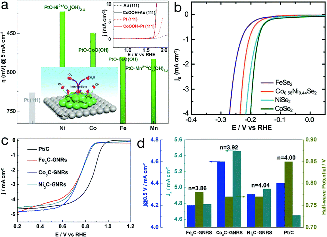 | ||
| Fig. 2 Electrocatalytic performance of unary 3d TM-based catalysts. Comparison of required overpotential for single-metal TM hydro(oxy)oxides in the OER. Reproduced with permission from ref. 26, Copyright 2012, Nature Publishing Group. (b) HER polarization curves of metal selenides. Reproduced with permission from ref. 30, Copyright 2013, the Royal Society of Chemistry. (c) ORR polarization curves and (d) the corresponding j@0.5 V vs. RHE, half-wave potential (E1/2), kinetic-limiting current density (Jk) and electron transfer number (n) of single-metal carbides and the Pt/C material (GNRs in (c) and (d) refers to graphene nanoribbons). Reproduced with permission from ref. 31, Copyright 2015, American Chemical Society. | ||
Moreover, to further improve the electrocatalytic performance of the TM-based materials, some advances have been achieved recently in terms of morphology, composition, surface and coordination, which will be reviewed below.
3. Morphology design
The evaluation of electrocatalytic performance generally refers to reactivity, Tafel slopes and durability, etc., which are severely dependent on the inherent physicochemical properties of materials, such as specific surface area. It has been well demonstrated that these physicochemical properties can be fine-tuned by modifying the morphology of the materials, for instance, the size and shape.32 The exploration of nanostructures is therefore of great importance in energetic electrocatalytic processes.To date, diverse nanostructures have been developed for rapid electrochemical conversion processes. As summarized in Fig. 3, these nanostructures mainly have hollow interiors and low dimensions for more accessible active sites and better electrical conductivity. For 0-dimensional (0D) nanoparticles, when the sizes in three dimensions are reduced to the nanoscale, some structural advantages will emerge, resulting in high electrocatalytic activity. Some nanoarchitectures are therefore elaborately designed. A current-induced high-temperature (≈2470 K) rapid thermal shock (≈12 ms) was adopted on iron pyrite (FeS2) bulks, leading to the successful preparation of FeS2 nanoparticles stabilized on reduced graphene oxide (indicated as nano-FeS2-rGO). Compared with its microsized counterparts (denoted as micro-FeS2-rGO), nano-FeS2-rGO has shown a lower onset potential, and a lower overpotential at a current density of 10 mA cm−2 with a smaller Tafel slope (66 mV dec−1).33 The enhanced activity is ascribed to the morphological advantage of the ultrafine nanoparticles, which may provide more accessible active sites and faster electron transfer. Similarly, a progressive cation exchange reaction of the octahedral shaped oxide precursors was developed for the synthesis of Co9−xNixS8 octahedral nanocages with a size of ∼80 nm.34 Because of the structural merit, they needed a low overpotential of only 364 mV to reach the anodic current density of 10 mA cm−2, even surpassing the commercial RuO2 material. When the nanoparticles were further minimized to the atomic size, single-atom catalysts were achieved. Since the first report on single-atom Pt (Pt1) supported on FeOx by Zhang's group in 2011,35 single-atom catalysts have attracted great research interest. In contrast to the conventional electrocatalysts, each active metal site in single-atom nanostructures is isolated from others, resulting in higher atom utilization and catalytic activity. Different from the Pt1/FeOx material in the first report, the TM-based single-atom catalysts usually use electronically conductive carbon materials, e.g., graphene or carbon nanotubes, as supports derived from the corresponding metal–organic precursors.36,37 Due to the structural feature, i.e. all metal atoms are isolated with other congeneric sites and bridged by neighboring carbon and/or nitrogen atoms, a high utilization ratio of nearly 100% for the metal sites can be realized by the single-atom structures. However, on account of the structural characteristics, the loading mass of the TM sites in single-atom catalysts is generally low (<5 wt%). It will be a great challenge to increase the loading of active metal sites in single-atom nanostructures.
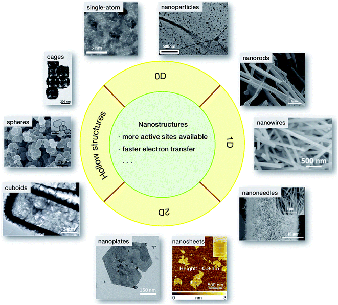 | ||
| Fig. 3 Nanostructured catalysts for electrochemical conversions: 0D nanoparticles33 and single-atom catalysts;36 1D nanorods,40 nanowires41 and nanoneedles;42 2D nanoplates,47 and nanosheets (the inset shows the visible Tyndall effect of the nanosheet dispersion);48 hollow cuboids,52 spheres53 and cages.54 Adapted with permission: nanoparticles: ref. 33, Copyright 2017, hollow cuboids, ref. 52, Copyright 2016, hollow spheres, ref. 53, and hollow cages: ref. 54, Copyright 2017, John Wiley & Sons, Inc.; sing-atom catalysts: ref. 36, Copyright 2018, nanoplates: ref. 47, Copyright 2014, Nature Publishing Group; nanorods: ref. 40, Copyright 2012, nanowire: ref. 41, Copyright 2017, nanosheets: ref. 48, Copyright 2015, American Chemical Society. | ||
Although 0D nanoarchitectures have attained impressively high performance in electrocatalytic processes, substantial endeavors have also been made in exploiting 1-dimensional (1D) electrocatalysts. Compared with 0D electrocatalysts, 1D nanostructures (such as nanorods, nanofibers, and nanowires) are beneficial for the extensive exposure of specific facets due to the preferential crystal growth, which may be advantageous for highly efficient electrocatalysis. The 1D structural features may also bring about path-directing effects in catalyst electrodes, greatly enhancing the electron transport properties.38,39 Moreover, it is notable that for single-crystalline 1D motifs, almost no defects exist on the surfaces, which endows these materials with ideal long-term electrocatalytic durability. For example, a solvothermal process at an elevated temperature of 190 °C was adopted for high-crystalline 1D CaMn2O4 nanorods.40 Due to the structural features, CaMn2O4 nanorods have been characterized to exhibit comparable onset potential and exchange current density to the benchmark Pt/C material for the ORR. In addition, as a result of the high crystallinity, in a long-term electrocatalytic process, the current decay for CaMn2O4 nanorods is only 12.3%, lower than that for commercial Pt/C materials (17.7%), revealing a better durability. In particular, conductive matrices, such as carbon cloth (CC), have been widely used, which can promote directing growth along the orientated directions, resulting in 1D nanoarrays. Since these nanoarrays are stabilized on the substrates, aggregation is effectively avoided so that the electrocatalytic reactants and intermediates can move freely though the interspace, which has been well demonstrated by NiMoP2 nanowires/CC.41 Due to the excellent performance in both OER and HER, NiMoP2 nanowires/CC were adopted as bifunctional electrocatalysts for overall water splitting, achieving galvanostatic electrolysis at a current density of 10 mA cm−2 at a low potential of ∼1.5 V for over 24 h with no obvious potential fluctuation. Similarly, because of beneficial structural features, 1D NiCo2Px nanoneedles/carbon have also been proposed to show comparable HER activity towards commercial Pt/C catalysts in both acidic and alkaline electrolytes.42 The X-ray diffraction and microscopic analyses of the sample after a chronoamperometry measurement for up to 30 h further confirmed that both the composition and the 1D morphology were well preserved. These 1D nanoarrays with peculiar structural merits deliver considerable electrocatalytic activity, stability and durability, promising more possibilities as candidates for replacing commercial electrocatalysts.
For 2-dimensional (2D) nanomaterials, exfoliated from layered crystalline structures, a larger specific surface area is expected. When a dimensional confinement is imposed, these materials will exhibit facile electron and/or ion transfer properties in comparison to the bulk structures,43–45 which is beneficial for the electrocatalytic processes. Stimulated by this point, many 2D nanostructures have been synthesized, such as NiCo and/or CoCo layered double hydroxide (LDH) nanoplates via a topochemical approach46 or NiFe LDH through a hydrothermal process.47 When the LDH nanoplates were further exfoliated into single-layered nanosheets, the electrocatalytic activity increased sharply. The overpotential at an anodic exchange current density of 10 mA cm−2 was reduced to 0.30 V for the exfoliated NiFe LDH nanosheets, much lower than that for the bulk counterparts (0.35 V). As is well known, poor electronic conductivity limits the high activity of hydroxides. The combination of electrocatalytically active materials and conductive matrices is an effective approach for further improving the electrocatalytic performance. In common composites or hybrids, conductive matrices and the electrocatalytically active phases are in rather low contact areas, which is not favorable for instant electron or ion transfer. However, 2D superlattice nanostructures may provide a substantial advantage. In our previous work, as displayed in Fig. 4, positively charged single-layered NiFe LDH nanosheets were obtained by the exfoliation of the corresponding bulk counterparts.48 Meanwhile, negatively charged graphene oxide (GO) nanosheets were prepared by the delamination of natural graphite bulks using a modified Hummers' method.49 Then, the superlattice nanostructure was formed by the flocculation of electrocatalytically active NiFe LDH nanosheets and electronically conductive reduced GO (rGO) nanosheets according to an area-matching model based on electrostatic interactions. The nanostructured composites combined the characteristic advantages of redox-active NiFe LDH and conductive graphene-related materials. As a result, the NiFe LDH/rGO superlattice nanostructure reached an exchange current density of 10 mA cm−2 at a rather low overpotential of 0.217 V. Furthermore, a small Tafel slope of 40 mV dec−1 and a high turnover frequency of ∼0.1 s−1 at an overpotential of 300 mV were achieved, far surpassing those of the NiFe LDH/GO superlattice and NiFe LDH nanosheets and making this material the state-of-the-art NiFe-based electrocatalyst. Due to the excellent activity in the kinetically slow OER, overall water splitting, as shown in Fig. 4i, could readily be driven by a 1.5 V size AA battery using the NiFe LDH/rGO superlattice as a bifunctional HER and OER electrocatalyst. Similarly, exfoliated NiMn LDH nanosheets were also prepared, which yielded a current density of 10 mA cm−2 at an overpotential of 0.36 V, with a Tafel slope of 65 mV dec−1. Upon further flocculation with electronically conductive rGO nanosheets, the NiMn LDH/rGO superlattice required an overpotential of only 0.26 V to reach an exchange current density of 10 mA cm−2 in the OER, surpassing most Mn-based electrocatalysts.50 In addition, MoS2/rGO superlattices were prepared by modifying and reversing the charge state of rGO, which resulted in an onset potential of 88 mV vs. RHE,51 much lower than that for pure MoS2 nanosheets (258 mV vs. RHE) and superior to those of other reported MoS2-based HER electrocatalysts.
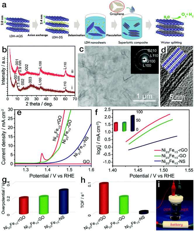 | ||
| Fig. 4 NiFe LDH nanosheet/rGO superlattice with high OER activity. (a) Schematic procedure for preparing the NiFe LDH/rGO superlattice. (b) XRD patterns for NiFe LDH/GO and NiFe LDH/rGO superlattices. (c) TEM and (d) HRTEM images of NiFe LDH/rGO superlattices. (e–h) Polarization curves, Tafel slopes, and overpotentials at a current density of 10 mA cm−2 and calculated TOF values for NiFe LDH/GO, NiFe LDH/rGO superlattices and NiFe LDH nanosheets in the electrocatalytic water oxidation process. (i) Photograph of the overall water splitting device using the NiFe LDH/rGO superlattice as a bifunctional electrocatalyst. Reproduced with the permission of ref. 48, Copyright 2015, American Chemical Society. | ||
Nanomaterials with hollow interiors have also been developed for efficient electrocatalytic reactions. For electrocatalysts with hollow nanostructures, compared with their solid counterparts, more accessible active sites can be provided, and good electron and mass transfers are realized due to the nanoscale wall thickness. Therefore, hollow nanostructures can endow the electrocatalysts with favorable reaction kinetics, i.e., a small Tafel slope. Gao et al. adopted Ni–Co based hollow microcuboid precursors as sacrificial templates for the hierarchical NiCo2O4 hollow microcuboids.52 These microcuboids possess two kinds of porosities: one is the mesopores which could be described by the BET theory, and the other is macropores as the hollow interior. Due to the hollow characters, NiCo2O4 microcuboids showed high activity as a bifunctional electrocatalyst for both HER and OER, by which a low applied potential of only 1.74 V is required to achieve an overall water splitting current of 20 mA cm−2 with a Tafel slope of 49.7 mV dec−1. Similar to TM oxides, TM sulfide-based electrocatalysts with hollow nanostructures have also been extensively investigated for use in electrocatalysis. Triblock copolymer pluronic P123 was used as a structure-directing agent for the preparation of hollow MoOx/Ni3S2 composite nanospheres with an ultrathin wall of <1.5 nm, which have exhibited comparable HER and OER activity towards commercial Pt/C and IrO2/C materials, respectively, with excellent durability in a long-term chronoamperometry process for up to 200 h, markedly surpassing the abovementioned noble metal-based electrocatalysts.53 Hollow NiFe diselenide nanocages were derived from a site-selective ammonia etchant-treated prussian-blue analog nanocage precursor.54 As a result, NiFe diselenide nanocages showed an outstanding OER activity of 10 mA cm−2 at a low overpotential of 240 mV accompanied by a small Tafel slope of 24 mV dec−1.
In fact, these nanostructured features are not mutually exclusive and can be addressed synchronously, such as by combining hollow nanoprisms with 2D nanosheets.55,56 These advanced nanostructures are helpful in improving electrocatalytic performance. However, in some electrocatalysts, the metal centers may still suffer from intrinsically low activity, which may be improved by strategies such as composition tuning and surface engineering, as described below.
4. Composition tuning
Among the numerous strategies for further boosting the catalytic performance of the electrocatalysts, composition tuning, such as atomic substitution, by which the electronic structures may be considerably tuned, has been considered one of the most effective approaches. In addition, constructing heterostructures (i.e. nano-compositing of two or more kinds of fundamental phases) is considered as another productive and popular strategy.4.1 Binary 3d TM-based electrocatalysts
Diaz-Morales and his coworkers have systematically demonstrated that superior electrocatalytic activity can be achieved by a rational doping process. Upon atomic-scale substitution, the electronic structure and the binding strength between the OER intermediates and the electrocatalyst surfaces can be optimized. As evidenced by the Sabatier-type volcano plot shown in Fig. 5a,57 the left leg refers to the strong adsorption on –O, revealing that the electrocatalytic OER is mainly limited by the transformation of *O into *OOH. In contrast, the right branch implies a weak attraction to –O, resulting in the conversion of *OH into *O as the rate-determining step for electrochemical water oxidation. When the atomic Ni sites are partially replaced by Fe, Mn or Cr, the required potential to efficiently drive the OER can be markedly reduced. Furthermore, it has also been shown that not all doping behaviors are beneficial for the enhancement of the electrocatalytic performance, such as introducing atomic Zn or Cu into the NiOOH matrix. Fan et al. have also demonstrated that for bimetallic LDH materials, compared with Fe incorporation, the introduction of V into Ni(OH)2 can realize more efficient water oxidation.58 As indicated in Fig. 5b, the onset overpotential is ∼250 mV for Ni0.75V0.25-LDH, much lower than the value of ∼300 mV for Ni0.75Fe0.25-LDH. At an overpotential of 350 mV, the exchange current density reached 27.0 ± 1.6 mA cm−2 by Ni0.75V0.25-LDH, far superior to the value of 11.7 ± 1.5 mA cm−2 achieved by Ni0.75Fe0.25-LDH. Meanwhile, the Tafel slope, ∼50 mV dec−1, was lower than the value of ∼64 mV dec−1 for Ni0.75Fe0.25-LDH, indicating more favorable mass transport and electron transfer for Ni0.75V0.25-LDH.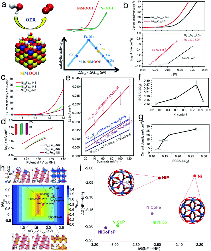 | ||
| Fig. 5 Binary and/or ternary 3d TM-based materials for improved electrocatalytic performance. (a) Experimental and theoretical OER activity of TM-doped NiOOH models. Reproduced with permission from ref. 57, Copyright 2015, American Chemical Society. (b) OER polarization curves and Tafel slopes for binary Ni0.75V0.25-LDH and Ni0.75Fe0.25-LDH. (c and d) Comparison of electrocatalytic OER activity for NiFe LDH nanosheets with different Ni/Fe ratios. Reproduced with permission from ref. 48, Copyright 2015, American Chemical Society. (e) ΔJ of NiV-LDH with various Ni contents plotted against the CV scan rate; (f) electrochemical active surface area of NiV-LDH with various Ni contents; (g) anodic current density at an overpotential of 350 mV plotted against the electrochemical surface area of NiV-LDH with incremental Ni contents for the electrocatalytic OER. (b and e–g) Reproduced with permission from ref. 58, Copyright 2016, Nature Publishing Group. (h) Calculated adsorption energies on –O and –OH by pure and doped oxyhydroxides and oxides. Reproduced with permission from ref. 61, Copyright 2016, the American Association for the Advancement of Science. (i) Gibbs free energy change for Ni2+ → Ni3+ → Ni4+. Reproduced with permission from ref. 64, Copyright 2018, Nature Publishing Group. | ||
Furthermore, many studies on binary TM-based electrocatalysts have shown that the electrocatalytic performance can be further significantly optimized by tuning the component proportions. For instance, as shown in Fig. 5c and d, it was found that Ni2/3Fe1/3 LDH nanosheets exhibited a higher anodic current density and a smaller Tafel slope than both Ni3/4Fe1/4 and Ni4/5Fe1/5 LDHs in the electrocatalytic OER.48 The largest electrochemical active area was obtained by optimizing the molar ratio of Ni/V to 3, as shown in Fig. 5e–g, resulting in the highest electrocatalytic OER activity for binary NiV-LDH.58 NiCo2Se4 nanosheets have also been demonstrated to show higher reactivity than Ni2CoSe4 and Ni1.5Co1.5Se4 in electrocatalytic water oxidation.59
In addition to metal substitution, nonmetal elemental incorporation can also effectively tune the electronic structure of the materials, enhancing the electrocatalytic activity. Pristine Co3O4 displays semiconductive characteristics with a band gap of ∼1.5 eV. Xiao et al. employed Ar plasma etching for the formation of oxygen vacancies in Co3O4 (herein, the product is labeled as VO–Co3O4).60 The octahedral Co3+–O bonds were therefore destroyed. They further treated the VO–Co3O4 sample with Ar plasma in the presence of a phosphorus (P) precursor to obtain a P-doped Co3O4 (denoted as P-Co3O4) sample. The coordination analyses showed that after the subsequent plasma treatment, P atoms filled in the generated oxygen vacancies. The computational electronic properties showed that P filling can further lower the bandgap to ∼0.3 eV in comparison with ∼0.8 eV for VO–Co3O4, implying a more positive electrical conductivity. When these three materials were applied in the electrocatalytic HER, the onset potential for P-Co3O4, ∼0.05 V vs. RHE, was far lower than the values of 0.36 and 0.35 V vs. RHE for pristine Co3O4 and VO–Co3O4, respectively, indicating the activity improvement by nonmetal P doping.
4.2 Ternary 3d TM-based electrocatalysts
As aforementioned, single element substitution can effectively change the electronic structure. To further optimize the electronic configurations as well as the adsorption energy, multiple element co-substitution has emerged. Density functional theory (DTF) shows that the high-valence non-3d TMs, such as W6+, can also considerably modulate 3d TM-based electrocatalysts, providing near-ideal adsorption energies for the intermediates. Based on this point, as depicted in Fig. 5h, Zhang et al. introduced Fe and W into β-CoOOH to obtain ternary FeWCo oxyhydroxide.61 Because of the interactions between Fe3+ and Co4+, the *O to *OH adsorption energy difference (ΔG*O − ΔG*OH) of the initial β-CoOOH was optimized by single-metal Fe doping. After further introducing W into Fe-doped β-CoOOH, the replacement of W at Co4+ resulted in preferential formation of high-valence W6+ due to the electron transfer process. Moreover, the W dopant with a larger atomic size might cause compressive strain on neighboring Co sites. As a result of codoping with W and Fe, FeWCo oxyhydroxide gained an anodic current density of 10 mA cm−2 at an overpotential of 191 mV, lower than those of both unary Co and binary FeCo oxyhydroxides. Enlightened by this innovative work, some further optimizations have been carried out. Pi and his coworkers investigated the relationship between the electrocatalytic activity of FeWCo oxyhydroxide and the elemental proportions, indicating that FeWCo oxyhydroxide with an optimal Fe content of 10% achieved a favorable Tafel slope of 32 mV dec−1 and the lowest overpotential of 310 mV to deliver the current density of 100 mA cm−2.62The simultaneous incorporation of metal and nonmetal elements has also arisen recently as another type of co-substitution strategy. High-valence TM ions, such as Ni4+, in metal oxides have been revealed to contribute a higher activity for electrocatalytic water oxidation.63,64 However, in neutral electrolytes, the TM ions prefer to be in a relatively low-valence oxidation state, such as Ni2+. To reach the desired high oxidation state for the TM sites, as displayed in Fig. 5i, Zheng et al. developed a codoping strategy of incorporating Co, Fe and nonmetal P.65 The NiCoFeP oxyhydroxide showed a current density of 1 mA cm−2 at a rather low overpotential of 276 mV, far lower than the values of 390 mV for NiP oxyhydroxide and 330 mV for NiCoP oxyhydroxide, indicating the highest reactivity for the electrocatalytic OER in a neutral electrolyte. The DFT+U calculations show that substitutional doping of Ni by P substantially lowers the Gibbs free energy change during the Ni2+/Ni3+ oxidation process, while the introduction of Co and Fe will further decrease the transformation energy from Ni3+ to Ni4+. As a result of the codoping of Co, Fe and nonmetal P, the formation of Ni4+ was consistently promoted by reducing the required transition energy, resulting in the high activity of NiCoFeP oxyhydroxide.
4.3 Heterostructures
Heterostructures refer to the integration of two or more different materials. When these fundamental materials are intimately bonded, besides the inherited physicochemical properties of the parent matters, some new characters, associated to the synergetic effects, can also be generated at the heterointerfaces, contributing to improved electrocatalytic activity. Bao's group has demonstrated a CoNi cluster@graphene core@shell structure, as shown in Fig. 6a.66,67 Their DFT calculations, as depicted in Fig. 6b and c, indicated that the adsorption of H* is too strong or weak on the CoNi alloy or the graphene shell. However, for the core@shell structure, the increase in electron density may occur on the graphene layers near the CoNi cluster, contributing to higher affinity on *H for graphene layers and therefore beneficial for the HER activity. The experimental result, as can be seen in Fig. 6d, also confirmed that high HER activity of CoNi cluster@graphene was even close to the commercial Pt/C electrocatalyst. Meanwhile, a similar improvement in OER activity originating from the heteroassembly with graphene has also been found.68 As indicated in Fig. 6e–g, compared with pure Ni–Al LDH or Ni nanoplates, the heterostructures, i.e. Ni–Al LDH/rGO and Ni/rGO, exhibited considerably enhanced activity. For instance, the NiAl-LDH/rGO composite required an overpotential of only 380 mV with a Tafel slope of 89 mV dec−1,68 far surpassing pure Ni–Al LDH and even overpassing metallic and redox-active Ni nanoplates. An Fe2P/N-doped reduced graphene oxide (Fe2P/NGO) composite, as depicted in Fig. 6h–j, has also been demonstrated to possess markedly higher activity than pure Fe2P, NGO and the physical mixture of Fe2P and NGO (denoted as Fe2P + NGO), confirming the synergetic effects beneficial for an efficient HER.69 Besides graphene-related materials, compositing with other conductive materials, such as 1T MoS2, has also been unveiled to show a striking merit in electrocatalytic processes. Zhang et al. have demonstrated the interfacial cooperation at Ni(OH)2/MoS2 heterointerfaces, as displayed in Fig. 6k–m.70 Ni(OH)2 provides the active sites for –OH adsorption while MoS2 accelerates the adsorption of H* intermediates. This synergistic effect substantially reduced the energy barrier of the initial water dissociation and the subsequent H2 generation. Experimental results also confirmed the activity improvement by the Ni(OH)2/MoS2 composite.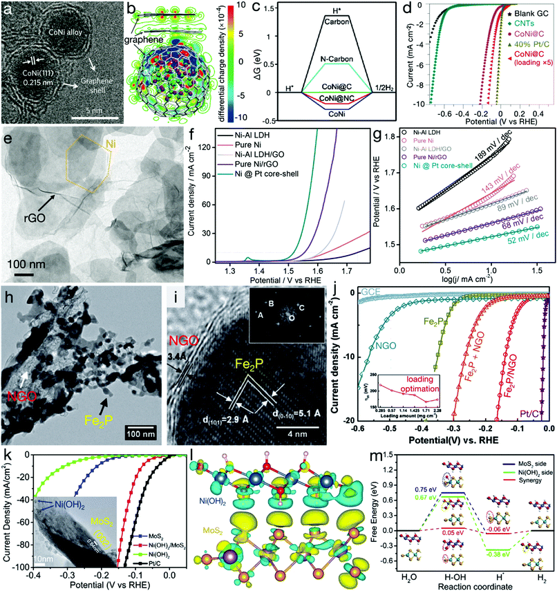 | ||
| Fig. 6 Heterostructures for electrocatalytic processes. (a) TEM image and (b) distribution of the electron densities of CoNi clusters@graphene core@shell nanostructures. Green and purple balls represent Ni and Co atoms, respectively. (c) Gibbs free energy profile of HER and (d) HER polarization curves of carbon nanotubes (CNTs), CoNi@graphene (or CoNi@carbon) and commercial Pt/C electrocatalysts. (a, b and d) Reproduced with permission from ref. 66, Copyright 2016, Nature Publishing Group and (c) reproduced with permission from ref. 67, Copyright 2015, John Wiley & Sons, Inc. (e) TEM image of hexagonal Ni nanoplates/rGO composites, (f) LSV curves for OER and (g) Tafel slopes of NiAl LDH precursors, pure Ni, NiAl LDH/GO, Ni/rGO and Ni@Pt composites. Reproduced with permission from ref. 68, Copyright 2015, American Chemical Society. (h) TEM and (i) HRTEM images of Fe2P/NGO composites, (j) LSV curves of NGO, Fe2P, Fe2P/NGO composites, the Fe2P + NGO mixture, and the commercial Pt/C electrocatalyst. Reproduced with permission from ref. 69, Copyright 2015, Elsevier Inc. (k) Polarization curves of Ni(OH)2/MoS2 composites, Ni(OH)2, MoS2 and commercial Pt/C electrocatalysts. The inset is the TEM image of Ni(OH)2/MoS2 composite. (l) Isosurfaces of the local charge density difference of the Ni(OH)2/MoS2 heterointerface; red, white, blue, purple and orange balls stand for H, O, Ni, Mo and S atoms, respectively. (m) Free energy diagram for HER on the MoS2 and/or Ni(OH)2 side, and the Ni(OH)2/MoS2 heterointerface. Reproduced with permission from ref. 70, Copyright 2017, Elsevier Inc. | ||
5. Surface engineering
Electrocatalysis processes mainly proceed on the surfaces of electrocatalysts; thus, active surfaces with different atom arrangements and coordination environments,71,72 possessing diverse electronic structures, will manifestly affect the adsorption sites as well as the binding strengths of the reactants and the reactive intermediates. Rational design of the exposed surface of the electrocatalysts is therefore considered the most promising strategy for tailoring the activity of the electrocatalysts.5.1 Exposed high-activity facets
The activity of shape-controlled catalysts has been studied for decades. In contrast to those with irregularly defined morphology, the specific facet-exposed catalysts are enclosed by peculiar atom arrangements. Furthermore, the surface atoms are considered to be coordinatively unsaturated in comparison to the interior atoms, showing rather different physicochemical features. For Co3O4 catalysts, the internal Co3+ atoms are located in the center of [CoO6] polyhedra. However, on the surface, Co3+ atoms are in unsaturated coordination environments and are linked with numerous dangling bonds.73 For {111} facets, the Co3+ dangling bond density is 0.32 Å−2, markedly higher than that of 0.06, 0.09 and 0.13 Å−2 for {001}, {110} and {112} facets, respectively. Moreover, due to the surface atom arrangement, the density of state (DOS) near the Fermi level surges notably, indicating more charge carriers and better intrinsic conductivity for the catalyst enclosed by {111} facets. As a result of the more active sites and the better transfer characters, Co3O4 nanocrystals exposed with {111} facets show better HER and OER performance. In addition, high-activity facets have also been developed for other analogous electrocatalytic materials, such as {0![[2 with combining macron]](https://www.rsc.org/images/entities/char_0032_0304.gif) 4} facets of CuFeS2 for HER,74 {100} facets of Cu2O for ORR,75 {111} facets of Ni octahedra for OER76 and {100} facets of MnO for both OER and ORR.77 To exploit the appropriate candidates for noble metal-based materials, more effort needs to be invested in seeking the high-activity facets of TM-based electrocatalysts.
4} facets of CuFeS2 for HER,74 {100} facets of Cu2O for ORR,75 {111} facets of Ni octahedra for OER76 and {100} facets of MnO for both OER and ORR.77 To exploit the appropriate candidates for noble metal-based materials, more effort needs to be invested in seeking the high-activity facets of TM-based electrocatalysts.
5.2 Defect design
Introducing surface defects is considered another paramount route to influence the electron configurations and thus the surface chemical processes of the catalysts. It has been reported that when oxygen vacancies are introduced on {100} facets of titanium oxide (TiO2), the band structure is enormously changed, making it possible for the catalytic HER to proceed under visible light irradiation.78 Similar advances have also emerged in electrocatalysts. For example, Ling and his coworkers prepared single-crystalline cobalt monoxide nanorods (SC CoO NDs) with exposed O vacancy-rich pyramidal nanofacets, as depicted in Fig. 7a–i.79 Through a cation exchange treatment at a relatively high temperature, high-index facets with high surface energy and sufficient oxygen vacancies were compelled to be exposed. As shown in Fig. 7j and l, due to the combined merits of the oxygen vacancies and advanced 1D nanoarchitectures, the kinetic-limiting Jk value and the exchange current density of SC CoO NDs were approximately 4.2 and 1.5 times greater than that of the polycrystalline CoO nanocrystals, respectively, suggesting the improved electrocatalytic activity for SC CoO NDs. DFT calculations also confirmed that the adsorption energy change |ΔG| for O-vacant {111} facets was close to 0 in both OER and reversible ORR, providing theoretical assistance for enhanced activities. When the electrocatalytic performance was decoupled from the contribution of the nanostructures, i.e., the current density was normalized by the electrochemical active surface area, as evidenced by Fig. 7k and m, the intrinsic ORR and OER reactivity of the SC CoO NDs was calculated to be 7.2 and 2.6 times, respectively, remarkably higher than that of polycrystalline CoO materials. Likewise, Zhao et al. have uncovered that the metal or oxygen-vacancies can endow the NiFe LDH nanosheets with semi-metal conductivity, and thus favorable charge transfer characters, resulting in improved OER activity with a low overpotential of 254 mV to achieve the exchange current density of 10 mA cm−2, superior to 280 mV for monolayered LDH nanosheets and 320 mV for the bulk counterpart.80 Similar activity improvements induced by defects have also been uncovered on other congeneric materials.81–84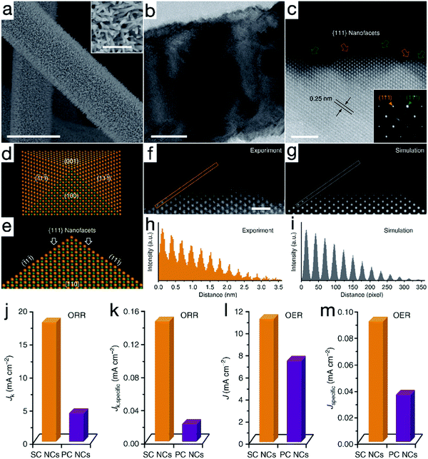 | ||
| Fig. 7 Single-crystalline CoO nanorods (SC CoO NRs) with oxygen vacancies for OER and ORR. (a) SEM, (b) TEM and (c) high-resolution HAADF-STEM images of SC CoO NRs. (d and e) Atomic model of a nanopyramid. (f and g) Experimental and simulated HAADF-STEM images of the pyramidal structure, respectively. (h and i) Intensity profiles taken from the orange and gray lines in (f and g), respectively. Comparison of ORR and OER activity for SC CoO NCs and polycrystalline CoO nanocrystals (PC CoO NCs) (j and l) before and (k and m) after normalization. Reproduced with permission from ref. 79, Copyright 2016, Nature Publishing Group. | ||
5.3 Surface wettability
As mentioned above, the electrocatalytic performance is closely related to the number of accessible active sites of the catalysts. The adsorption of the reactants and the reactive intermediate products, determined by the surface wettability, also plays a crucial role. Suitable wettability may tune the binding with the reactants and/or intermediate products, thus increasing the number of active sites as well as the electrocatalytic activity. Inspired by the attractive electrocatalytic properties of the phosphates and the hydrophilicity enhancement derived from the amorphous phases,85,86 phosphorylation by phosphorus vapor has been adopted for surface wettability modification, as shown in Fig. 8.87 After the phosphorylation process, the surface of NiFe LDH was partially transformed into an amorphous NiFe phosphate phase (denoted as NiFe:Pi). The contact angle substantially decreased from 129 ± 5° for NiFe LDH to 44 ± 3° for NiFe/NiFe:Pi. As a result of the wettability improvement, the number of accessible active sites almost doubled, as evidenced by the cyclic voltammetry (CV) scans. The polarization curves showed that for the NiFe/NiFe:Pi sample, the anodic current density exponentially grew after the potential of 1.5 V vs. RHE, which is far superior to pristine NiFe LDH. Furthermore, both the Tafel slope and electrochemical impedance data imply far more favorable kinetics for NiFe/NiFe:Pi.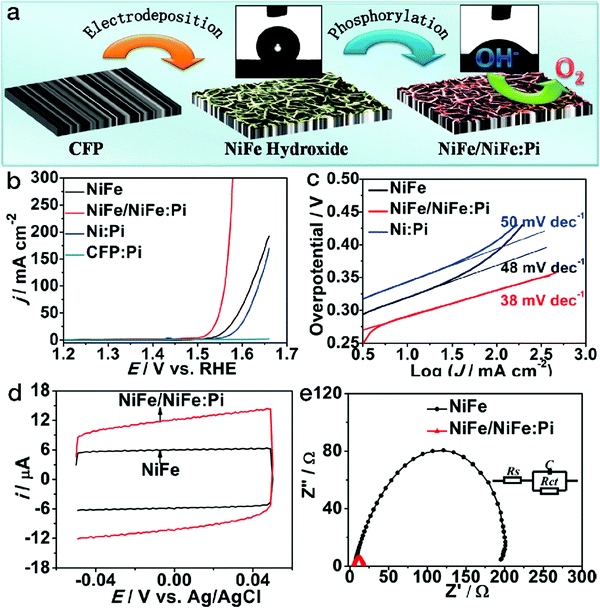 | ||
| Fig. 8 Phosphorylation treatment on NiFe LDH for better wettability in electrocatalytic water oxidation. (a) Schematic of NiFe/NiFe:Pi nanostructures fabricated by electrodeposition followed by a phosphorylation process. (b) OER polarization curves, (c) Tafel slopes, (d) CV scans and (e) electrochemical impedance spectra of NiFe LDH and NiFe NiFe/NiFe:Pi electrocatalysts. Reproduced with permission from ref. 87, Copyright 2016, American Chemical Society. | ||
6. Metal coordination symmetry/geometry control
It is well known that TM atoms are favorably coordinated in the forms of [TMO6], such as [CoO6] in β-Co(OH)2 or Co-containing LDHs.88,89 Our group has reported that tetrahedral [TMO4] geometries with lower symmetry may exist in some metastable phases, such as α-Co(OH)2.90,91 Low-symmetry or open metal coordination environments, especially seriously distorted coordination configurations, possess strong adsorption to small molecules (such as water and methanol) and have been widely used in the H2 storage and catalysis fields for metal–organic frameworks (MOFs).92–94 The adsorption characteristics of these low-symmetry metal coordination geometries may also be feasible on the electrocatalytic reactants as well as the intermediate products, resulting in peculiar electrocatalytic reactivity. Inspired by this point, coordination geometry design has recently emerged for exploiting high-performance electrocatalysts.6.1 Metal-O coordination
Generally, the TM centers in inorganic compounds tend to adopt 4- and/or 6-coordination geometries. Recently, Kim and her coworkers revealed the relationship between the electrocatalytic activity and the coordination geometry, i.e., in comparison with NaCoPO4 containing conventional 6-coordinated Co atoms, 4-coordinated Na2CoP2O7 showed obviously higher OER activity,95 suggesting that the electrocatalytic performance could be markedly improved by tuning the coordination environment of the active metal sites. In view of the adsorption characteristics of the low-symmetry metal centers, our group first reported the electrochemical properties of tetragonal pyramidal [CoO]5 coordination environments, uncovering the higher OER performance of these low-symmetry geometries compared with the conventional [CoO4] tetrahedrons.96NaCo4(PO4)3 is highly evaluated as a unique compound since all Co sites are in low-symmetry 5-coordination sites. As shown in Fig. 9a and b, different from conventional trigonal bipyramidal [CoO5] configurations with Co atoms in the body center, the [CoO5] structure in this compound is close to tetragonal pyramidal in shape, with each Co active site located on the bottom surface of the coordination geometry, which may lead to a more favorable adsorption on electronegatively charged oxygen atoms from water molecules. As indicated in Fig. 9c–f, benefitting from the peculiar [CoO5] coordination environments, NaCo4(PO4)3 nanoribbons achieved markedly higher OER activity and more favorable water oxidation kinetics than traditional Na2CoP2O7 with all Co atoms in tetrahedral [CoO4] forms. The half wave at a relatively low potential of 1.41 V vs. RHE refers to the adsorption of water molecules by the [CoO5] geometries of NaCo4(PO4)3 nanoribbons, accompanied by the oxidation of Co(II) to Co(III). When being normalized by the electrochemical active surface area, the electrocatalytic activity of each [CoO5] configuration at a given potential, such as 1.7 V vs. RHE, was calculated to be twice that of the [CoO4] tetrahedron. As a merit of the unique coordination, intrinsic electrical conductivity and nanoribbon morphology, NaCo4(PO4)3 yielded current densities of 1.0 and 11.0 mA cm−2 at low overpotentials of 0.373 and 0.570 V, respectively. The high-activity NaCo4(PO4)3 nanoribbons were even comparable to the benchmark RuO2 nanoparticles, outperforming most of the recently reported TM-based catalysts, such as atomically thin Co3S4 nanosheets and congeneric cobalt phosphate/GO composites.
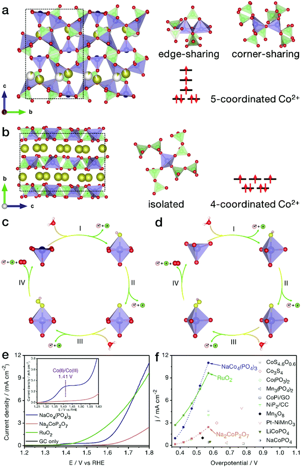 | ||
| Fig. 9 NaCo4(PO4)3 with [CoO5] pyramids for the electrocatalytic OER. Crystal structure models of (a) NaCo4(PO4)3 and (b) Na2CoP2O7 phases. The brown, red, green and blue balls represent Na, O, P and Co atoms, respectively, while the white balls represent partially occupied Na sites. A possible OER mechanism for (c) NaCo4(PO4)3 and (d) Na2CoP2O7 products in the electrocatalytic OER. The yellow and light pink balls represent adsorbed oxygen and hydrogen atoms, respectively. (e) Polarization curves of NaCo4(PO4)3, Na2CoP2O7 and benchmark RuO2 nanoparticles. (f) Comparison of OER activity between NaCo4(PO4)3 nanoribbons and recently reported electrocatalysts. Reproduced and modified with permission from ref. 97, Copyright 2018, American Chemical Society. | ||
6.2 Metal-N coordination
Newly emerging single-atom TMs in N-doped carbon matrix (N–C) materials have attracted wide interest due to their unique structural features and excellent performance in electrocatalytic processes and are therefore regarded as promising Pt alternatives.97 N–C matrices have been reported to be prepared by either the thermolysis of C,N-containing organic precursors (such as polydopamine)98 or the nitridation of carbon materials.36 The introduced N content in the carbon skeletons contributes to better electrical conductivity in comparison to the pristine carbon materials. Meanwhile, due to the strong chemical binding, the N sites can also act as anchors for the immobilization of metal moieties. Due to the layered crystalline structure of carbon matrices, the metal atoms are usually in open planar coordination environments, e.g., [TMN4]. Bao's group has reported that by the pyrolysis of iron phthalocyanine (FePc, C32H16FeN8), an Fe–N–C structure containing planar [FeN4] coordination sites was obtained.99 As displayed in Fig. 10a and b, the isolated black dots indicate Fe atoms. The detected position of a single Fe site in the graphene nanosheet (GN) matrix matches well with that of the atomic [FeN4] model, as shown in Fig. 10c and d. Meanwhile, as demonstrated by the atomic-resolution scanning tunneling microscopy (STM) image in Fig. 10e–g, the bright dot corresponds to the Fe atom, while the four neighboring atoms show a higher apparent height than the carbon atoms far away from the Fe center. This observation is identical to the STM simulation of the graphene lattice with [FeN4] embedded. All the HRTEM and STM observations and scanning tunneling spectroscopy (STS) results confirmed the stable existence of [FeN4] coordination in the plane of graphene. When the unique Fe–N–C materials were applied in the electrocatalytic ORR, as shown in Fig. 10h–j, FeN4/GN-2.7 (wherein 2.7 indicates an Fe content of 2.7%) showed a comparable polarization curve to the commercial Pt/C catalyst, revealing high ORR activity. After 7000 CV cycles in O2-saturated electrolyte, the onset potential and the limiting current of the commercial Pt/C catalyst declined notably. In contrast, the FeN4/GN-2.7 material still showed remarkably high ORR activity, surpassing the commercial Pt/C electrocatalyst.100 More importantly, the yield of the intermediate product H2O2 originating from the two-electron transfer pathway was less than 0.5% for FeN4/GN-2.7, markedly lower than that of 5% for the Pt/C material. DFT calculations also indicated that the oxygen molecules could readily be transformed into water via a four-electron pathway on the Fe sites of [FeN4] moieties.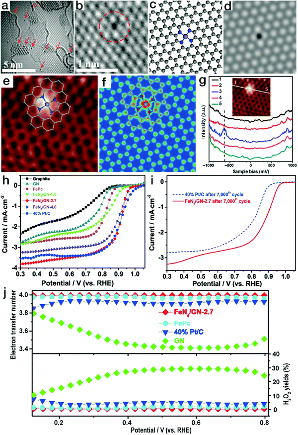 | ||
| Fig. 10 Single-atom Fe–N–C electrocatalysts with planar tetragonal [FeN4] configurations for ORR. (a and b) HRTEM images of FeN4/GN-2.7; (c) atomic model and the corresponding HRTEM simulation image for the Fe–N–C structure in (b). (e) STM image for FeN4/GN-2.7; (f) simulated STM image for the Fe–N–C structure in (e). (g) dI/dV spectra obtained along the white line in the inset image. The gray, blue and light blue balls in (c), (e), and (f) represent C, N, and Fe atoms, respectively. (a–g) Reproduced with permission from ref. 99, Copyright 2015, the American Association for the Advancement of Science. (h) ORR polarization curves for FeN4/GN, Pt/C and graphite; (i) ORR polarization curves for the FeN4/GN-2.7 sample before and after continuous CV scan; (j) electron transfer number and the H2O2 yield ratio for FeN4/GN-2.7, Pt/C, GN and FePc. (h–j) Reproduced with permission from ref. 100, Copyright 2017, Elsevier Inc. | ||
Another kind of TM–N coordination has also been demonstrated as [TMN2] moieties, exhibiting a higher ORR activity than [TMN4] counterparts. Yin and his coworkers have prepared two different Co–N coordination sites by tuning the calcination temperature of the bimetal ZnCo-MOF precursor (herein, the Zn content evaporates and is removed under high temperature conditions).101 The dominant Co single-atom sites are [CoN4] and [CoN2] for the Co–N–C species obtained at 800 and 900 °C (denoted as Co SAs/N–C (800) and Co SAs/N–C (900)), respectively. As indicated in Fig. 11, as a result of the high reactivity and high content of [CoN2] moieties, Co SAs/N–C (900) showed higher ORR activity than both Co SAs/N–C (800) and the Pt/C catalyst. The Tafel slope of 75 mV dec−1, lower than 79 mV dec−1 for Co SAs/N–C (800) and 96 mV dec−1 for Pt/C, revealed more favorable reaction kinetics for Co SAs/N–C (900) in the electrocatalytic ORR. Furthermore, Co SAs/N–C (900) possessed higher values of kinetic-limiting current density Jk and half-wave potential E1/2 than Co SAs/N–C (800) and the Pt/C catalyst, verifying the superior activity. Similarly, Guo's group proposed Fe atoms in the form of [FeN2] in N-doped ordered mesoporous carbon (NOMC).102 Due to the unique coordination configurations, the FeN2/NOMC material yielded a comparable polarization curve to the commercial Pt/C material in the electrocatalytic ORR. The E1/2 value, 0.863 V vs. RHE for FeN2/NOMC, was ∼30 mV more positive than that of the commercial Pt/C material. Furthermore, the Jk value was 45.2 mA cm−2, far superior to 16.2 mA cm−2 for the Pt/C catalyst, revealing higher ORR activity. Moreover, DFT calculations indicated that due to the lower interaction with *O2 and *OH intermediates in comparison with [FeN4] sites, [FeN2] moieties reduced the overpotential by ∼0.12 eV, contributing to the higher activity. The corresponding electrocatalytic parameters of these selected cases are listed in Table 1.
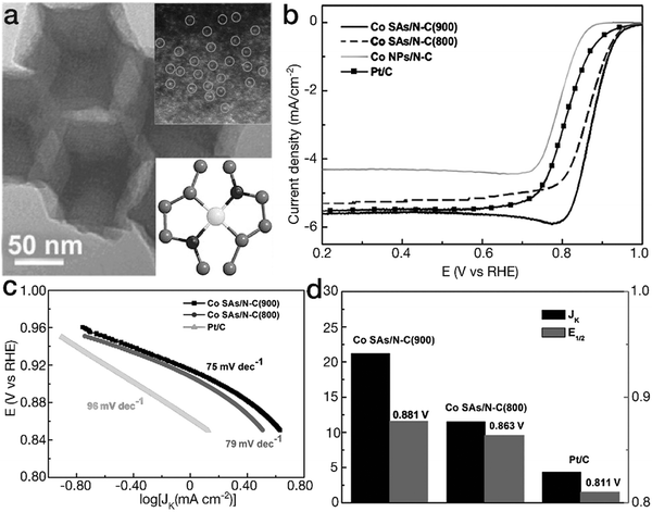 | ||
| Fig. 11 Planar tetragonal [TMN2] configurations for ORR. (a) TEM image for the Co SAs/N–C (900) sample. The insets represent the HAADF image and the structural model for planar [FeN2]. The black, gray and white balls represent N, C, and Co atoms, respectively. (b) ORR polarization curves, (c) Tafel slopes and (d) Jk and E1/2 for Co–N–C materials and the commercial Pt/C electrocatalyst. (a–d) Reproduced with permission from ref. 101, Copyright 2017, John Wiley & Sons, Inc. | ||
| Catalysts | Electrocatalysis | Electrolyte | Overpotential | Tafel slope (mV dec−1) | Ref. |
|---|---|---|---|---|---|
| Morphology design | |||||
| Nano-FeS2-rGO | HER | 0.5 M H2SO4 | 139 mV @ 10 mA cm−2 | 66 | 33 |
| Micro-FeS2-RGO | 260 mV @ 10 mA cm−2 | 124 | |||
| Co9−xNixS8 nanocages | OER | 1.0 M NaOH | 364 mV @ 10 mA cm−2 | 74.7 | 34 |
| CaMn2O4 nanorods | ORR | 0.1M KOH | 0.563 V vs. RHE@4.25 mA cm−2 | 64 | 40 |
| NiMoP2 nanowires | HER | 0.5 M H2SO4 | 195 mV @ 100 mA cm−2 | 56 | 41 |
| OER | 1.0 M KOH | 320 mV @ 10 mA cm−2 | 96.7 | ||
| NiCo2Px nanoneedles | HER | 1.0 M KOH | 58 mV @ 10 mA cm−2 | 34.3 | 42 |
| 1.0 M PBS | 63 mV @ 10 mA cm−2 | 63.3 | |||
| 0.5 M H2SO4 | 104 mV @ 10 mA cm−2 | 32.5 | |||
| NiFe LDH nanoplates | OER | 1.0 M KOH | 350 mV @ 10 mA cm−2 | 67 | 47 |
| NiFe LDH nanosheets | 300 mV @ 10 mA cm−2 | 40 | |||
| NiFe LDH/rGO superlattice | OER | 1.0 M KOH | 217 mV @ 10 mA cm−2 | 40 | 48 |
| NiMn LDH nanosheets | OER | 1.0 M KOH | 360 mV @ 10 mA cm−2 | 65 | 50 |
| NiMn LDH/rGO superlattice | 260 mV @ 10 mA cm−2 | 46 | |||
| Hollow NiCo2O4 cuboids | HER | 1.0 M NaOH | 110 mV @ 10 mA cm−2 | 49.7 | 52 |
| OER | 290 mV @ 10 mA cm−2 | 53 | |||
| Hollow MoOx/Ni3S2 nanospheres | HER | 1.0 M KOH | 106 mV @ 10 mA cm−2 | 90 | 53 |
| OER | 310 mV @ 100 mA cm−2 | 50 | |||
| NiFe diselenide nanocages | OER | 1.0 M KOH | 240 mV @ 100 mA cm−2 | 24 | 54 |
| Composition tuning | |||||
| Ni0.75V0.25-LDH | OER | 1.0 M KOH | 350 mV @ 27.0 ± 1.6 mA cm−2 | 50 | 58 |
| Ni0.75Fe0.25-LDH | 350 mV @ 11.7 ± 1.5 mA cm−2 | 64 | |||
| Ni4/5Fe1/5 LDH nanosheets | OER | 1.0 M KOH | 280 mV @ 5 mA cm−2 | 82 | 48 |
| Ni3/4Fe1/4 LDH nanosheets | 340 mV @ 5 mA cm−2 | 80 | |||
| Ni2/3Fe1/3 LDH nanosheets | 370 mV @ 5 mA cm−2 | 76 | |||
| P-Co3O4 | HER | 1.0 M KOH | 120 mV @ 10 mA cm−2 | 52 | 60 |
| OER | 280 mV @ 10 mA cm−2 | 51.6 | |||
| Co3Se4 | OER | 1.0 M KOH | 345 mV @ 10 mA cm−2 | 65 | 59 |
| NiCo2Se4 | 290 mV @ 10 mA cm−2 | 53 | |||
| Ni1.5Co1.5Se4 | 315 mV @ 10 mA cm−2 | 57.5 | |||
| Ni2CoSe4 | 310 mV @ 10 mA cm−2 | 65 | |||
| Ni3Se4 | 349 mV @ 10 mA cm−2 | 76 | |||
| FeCo oxyhydroxide | OER | 1 M KOH | 215 ± 6 mV @ 10 mA cm−2 | — | 61 |
| FeWCo oxyhydroxide | 191 ± 3 mV @ 10 mA cm−2 | — | |||
| NiP oxyhydroxide | OER | CO2-saturated 0.5 M KHCO3 | 588 mV @ 10 mA cm−2 | — | 65 |
| NiCoP oxyhydroxide | 547 mV @ 10 mA cm−2 | — | |||
| NiCoFeP oxyhydroxide | 330 mV @ 10 mA cm−2 | — | |||
| CoNi@graphene | HER | 0.1 M H2SO4 | 142 mV @ 10 mA cm−2 | 104 | 67 |
| Ni-Al LDH/rGO composite | OER | 1.0 M KOH | 380 mV @ 10 mA cm−2 | 89 | 68 |
| Ni/rGO composite | 330 mV @ 10 mA cm−2 | 68 | |||
| Fe2P/NGO | HER | 0.5 M H2SO4 | 138 mV @ 10 mA cm−2 | 65 | 69 |
| Ni(OH)2/MoS2 | HER | 1.0 M KOH | 80 mV @ 10 mA cm−2 | 60 | 70 |
| Surface engineering | |||||
| {111} facets-exposed Co3O4 | OER | 1.0 M KOH | 285 mV @ 10 mA cm−2 | 49 | 73 |
| HER | 195 mV @ 10 mA cm−2 | 50 | |||
| {100} facets-exposed Cu2O | ORR | 0.1 M KOH | E onset = 0.8 V | — | 75 |
| {100} facets-exposed MnO | ORR | 0.1 M KOH | E 1/2 = 0.77 V vs. RHE, ΔE = 1.02 V | — | 77 |
| O vacancies-rich CoO NDs | OER | 1.0 M KOH | 330 mV @ 10 mA cm−2 | 44 | 79 |
| ORR | E 1/2 = 0.85 V, ΔE = 0.71 V | 47 | |||
| Defected NiCo LDH | OER | 1.0 M KOH | 254 mV @ 10 mA cm−2 | 32 | 80 |
| NiFe LDH/NiFe:Pi | OER | 1.0 M KOH | 290 mV @ 10 mA cm−2 | 38 | 87 |
| Metal coordination symmetry/geometry control | |||||
| NaCo4(PO4)3 | OER | 0.05 M PBS | 373 mV @ 1 mA cm−2 | 121 | 96 |
| FeN4/GN | ORR | 1.0 M NaOH | E 1/2 = 0.91 V vs. RHE | — | 100 |
| [CoN2] + [CoN4]/N–C | ORR | 0.1 M KOH | E 1/2 = 0.881 V vs. RHE | 75 | 101 |
| FeN2/NOMC | ORR | 0.1 M KOH | E 1/2 = 0.863 V vs. RHE | 58 | 102 |
In addition, the activity of TM–N–O coordination configurations has also been investigated. Yang et al. analyzed the ORR performance of planar [MnNxO4−x] (x = 1, 2 or 3) coordination sites theoretically.103 Typically, for planar tetragonal Mn moieties, various Mn–N–O configurations exist, i.e., [MnN1O3], [MnN2O2] and [MnN3O1]. DFT calculations showed that as a merit of the proper downshift of the d-band center and the position of the first peak close to the Fermi level in [MnN1O3] geometries, desorption and formation of the intermediates were more favorable, resulting in the best ORR kinetics for [MnN1O3] among all the planar Mn–N–O configurations. However, until now, only the material with mixed [MnNxO4−x] (x = 1, 2 or 3) configurations has been prepared. More work needs to be performed for the synthesis of electrocatalysts containing a single type of TM–N–O structure, e.g., [MnN1O3], to further verify the theoretical analysis and explore the experimental reactivity.
7. Conclusions
In summary, we have reviewed recent progress in developing advanced 3d TM-based nanostructures to improve the electrocatalytic efficiency for renewable energy conversion. Several vital and versatile strategies regarding morphology design, composition tuning, surface engineering and metal coordination symmetry/geometry control have brought about considerably enhanced performance for TM-based electrocatalysts towards the electrocatalytic OER, HER and/or ORR. Some key issues, however, remain challenging and need to be addressed. For instance, incomplete two-electron reactions or generation of the byproduct H2O2 during oxygen reduction processes may still occur, which cause damage by etching away the electrocatalysts, severely reducing the activity as well as long-term durability, etc.The ultimate goal of developing effective electrocatalysts based on TM elements is to construct stable and high-efficiency energy conversion systems and devices. Hence, further work may be directed towards the following aspects. (i) More efforts may need to be focused on identifying the most ideal nanostructures for durable and efficient electrocatalysis. So far various electrocatalysts based on 3d transition metals and related nanoarchitectures have been constructed. It is necessary to choose the best structure on account of the cost, maximum utilization of metal sites, activity, the feasibility of large-scale fabrication and applications, etc. (ii) Composition, valence and component tuning should be further carried out to achieve the optimal activity. (iii) More favorable metal coordination geometries are expected due to their fascinating adsorption/desorption abilities. In addition, for an in-depth understanding of the reaction mechanism, it is urgent to introduce some in situ and/or ex situ techniques to characterize the real-time reaction states and changes of typical electrocatalysts during electrocatalysis. The advances in the combination of theoretical calculations and experimental approaches are deemed valuable in exploiting low-cost and high-performance electrocatalysts.
Many investigation cases have verified the high activity of nanostructured electrocatalysts based on 3d TM elements, providing a great potential for the gradual replacement of precious metal-based electrocatalysts. To meet the industrial use, more endeavors are expected for non-precious 3d TM-based materials. In particular, it is urgent to improve the structural stability and electrochemical durability of the electrocatalysts. Current proton exchange membrane (such as Nafion N115 membrane) fuel cells can work only in acidic environments.104 Thus, it is rather difficult to completely replace precious metal-based materials due to the low durability of TM-based electrocatalysts. To make full and practical use of the earth-abundant and cheap 3d TM sources, developing alkaline condition-related electrocatalytic devices or systems is prospective and should be greatly appreciated. For instance, due to the high activity, reversibility and hydroxyl-transfer characters,45,48,105 TM hydroxides can be regarded as a kind of important multifunctional material for the future electrolyzers. In this regard, designing and developing economical electrocatalysts for alkaline systems are significantly promising for sustainable energy conversion.
Conflicts of interest
There are no conflicts to declare.Acknowledgements
This work was supported in part by the WPI-MANA, Ministry of Education, Culture, Sports, Science and Technology, Japan. R. M. acknowledges the financial support from the JSPS KAKENNHI (18H03869). X. L. acknowledges the support from the National Natural Science Foundation of China (51874357 and 51872333) and the Hunan Provincial Natural Science Foundation of China (13JJ1005).Notes and references
- Z. W. Seh, J. Kibsgaard, C. F. Dickens, I. Chorkendorff, J. K. Nørskov and T. F. Jaramillo, Science, 2017, 355, 146 CrossRef PubMed.
- W. Zhang, W. Lai and R. Cao, Chem. Rev., 2017, 117, 3717 CrossRef CAS PubMed.
- S. Dey, B. S. Naidu and C. N. R. Rao, Chem. – Eur. J., 2015, 21, 7077 CrossRef CAS PubMed.
- B. Meredig and C. Wolverton, Phys. Rev. B, 2011, 83, 239901 CrossRef.
- J. Suntivich, K. J. May, H. A. Gasteiger, J. B. Goodenough and Y. Shao-Horn, Science, 2011, 334, 1383 CrossRef CAS PubMed.
- A. Holewinski, J. C. Idrobo and S. Linic, Nat. Chem., 2014, 6, 828 CrossRef CAS PubMed.
- J. R. McKone, E. L. Warren, M. J. Bierman, S. W. Boettcher, B. S. Brunschwig, N. S. Lewis and H. B. Gray, Energy Environ. Sci., 2011, 4, 3573 RSC.
- Y. Lee, J. Suntivich, K. J. May, E. E. Perry and Y. Shao-Horn, J. Phys. Chem. Lett., 2012, 3, 399 CrossRef CAS PubMed.
- W. Hu, Y. Wang, X. Hu, Y. Zhou and S. Chen, J. Mater. Chem., 2012, 22, 6010 RSC.
- X. Liu, R. Ma, Y. Bando and T. Sasaki, Adv. Mater., 2012, 24, 2148 CrossRef CAS PubMed.
- R. Ma, X. Liu, J. Liang, Y. Bando and T. Sasaki, Adv. Mater., 2014, 26, 4173 CrossRef CAS PubMed.
- Y. Zhao, L. Peng, B. Liu and G. Yu, Nano Lett., 2014, 14, 2849 CrossRef CAS PubMed.
- R. Lü, K. Shi, W. Zhou, L. Wang, C. Tian, K. Pan, L. Sun and H. Fu, J. Mater. Chem., 2012, 22, 24814 RSC.
- J. Han, S. Hao, Z. Liu, A. M. Asiri, X. Sun and Y. Xu, Chem. Commun., 2018, 54, 1077 RSC.
- C. Guan, X. Liu, A. M. Elshahawy, H. Zhang, H. Wu, S. J. Pennycook and J. Wang, Nanoscale Horiz., 2017, 2, 342 RSC.
- X. Chen, K. Shen, J. Chen, B. Huang, D. Ding, L. Zhang and Y. Li, Chem. Eng. J., 2017, 330, 736 CrossRef CAS.
- F. Ming, H. Liang, H. Shi, G. Mei, X. Xu and Z. Wang, Electrochim. Acta, 2017, 250, 167 CrossRef CAS.
- M. D. Meganathan, S. Mao, T. Huang and G. Sun, J. Mater. Chem. A, 2017, 5, 2972 RSC.
- X. Liu and L. Dai, Nat. Rev. Mater., 2016, 1, 16064 CrossRef CAS.
- J. S. Kim, B. Kim, H. Kim and K. Kang, Adv. Energy Mater., 2018, 8, 1702774 CrossRef.
- S. Anantharaj, S. R. Ede, K. Sakthikumar, K. Karthick, S. Mishra and S. Kundu, ACS Catal., 2016, 6, 8069 CrossRef CAS.
- F. Wang, T. A. Shifa, X. Zhan, Y. Huang, K. Liu, Z. Cheng, C. Jiang and J. He, Nanoscale, 2015, 7, 19764 RSC.
- F. Lu, M. Zhou, Y. Zhou and X. Zeng, Small, 2017, 13, 1701931 CrossRef PubMed.
- T. Wang, H. Xie, M. Chen, A. D’Aloia, J. Cho, G. Wu and Q. Li, Nano Energy, 2017, 42, 69 CrossRef CAS.
- C. Zhu, S. Fu, Q. Shi, D. Du and Y. Lin, Angew. Chem., Int. Ed., 2017, 56, 13944 CrossRef CAS PubMed.
- R. Subbaraman, D. Tripkovic, K. C. Chang, D. Strmcnik, A. P. Paulikas, P. Hirunsit, M. Chan, J. Greeley, V. Stamenkovic and N. M. Markovic, Nat. Mater., 2012, 11, 550 CrossRef CAS PubMed.
- W. T. Hong, M. Risch, K. A. Stoerzinger, A. Grimaud, J. Suntivich and Y. Shao-Horn, Energy Environ. Sci., 2015, 8, 1404 RSC.
- Y. Zhan, M. Lu, S. Yang, C. Xu, Z. Liu and J. Y. Lee, ChemCatChem, 2016, 8, 372 CrossRef CAS.
- J. Kibsgaard, C. Tsai, K. Chan, J. D. Benck, J. K. Nørskov, F. Abild-Pedersen and T. F. Jaramillo, Energy Environ. Sci., 2015, 8, 3022 RSC.
- D. Kong, J. J. Cha, H. Wang, H. R. Lee and Y. Cui, Energy Environ. Sci., 2013, 6, 3553 RSC.
- X. Fan, Z. Peng, R. Ye, H. Zhou and X. Guo, ACS Nano, 2015, 9, 7407 CrossRef CAS PubMed.
- Y. J. Wang, N. Zhao, B. Fang, H. Li, X. T. Bi and H. Wang, Chem. Rev., 2015, 115, 3433 CrossRef CAS PubMed.
- Y. Chen, S. Xu, Y. Li, R. J. Jacob, Y. Kuang, B. Liu, Y. Wang, G. Pastel, L. G. Salamanca-Riba, M. R. Zachariah and L. Hu, Adv. Energy Mater., 2017, 7, 1700482 CrossRef.
- J. Kim, H. Jin, A. Oh, H. Baik, S. H. Joo and K. Lee, Nanoscale, 2017, 9, 15397 RSC.
- B. Qiao, A. Wang, X. Yang, L. F. Allard, Z. Jiang, Y. Cui, J. Liu, J. Li and T. Zhang, Nat. Chem., 2011, 3, 634 CrossRef CAS PubMed.
- H. Fei, J. Dong, Y. Feng, C. S. Allen, C. Wan, B. Volosskiy, M. Li, Z. Zhao, Y. Wang, H. Sun, P. An, W. Chen, Z. Guo, C. Lee, D. Chen, I. Shakir, M. Liu, T. Hu, Y. Li, A. I. Kirkland, X. Duan and Y. Huang, Nat. Catal., 2018, 1, 63 CrossRef.
- C. Zhu, S. Fu, J. Song, Q. Shi, D. Su, M. H. Engelhard, X. Li, D. Xiao, D. Li, L. Estevez, D. Du and Y. Lin, Small, 2017, 13, 1603407 CrossRef PubMed.
- Z. Wen, S. Ci, F. Zhang, X. Feng, S. Cui, S. Mao, S. Luo, Z. He and J. Chen, Adv. Mater., 2012, 24, 1399 CrossRef CAS PubMed.
- C. Koenigsmann and S. S. Wong, Energy Environ. Sci., 2011, 4, 1161 RSC.
- J. Du, Y. Pan, T. Zhang, X. Han, F. Cheng and J. Chen, J. Mater. Chem., 2012, 22, 15812 RSC.
- X. D. Wang, H. Y. Chen, Y. F. Xu, J. F. Liao, B. X. Chen, H. S. Rao, D. B. Kuang and C. Y. Su, J. Mater. Chem. A, 2017, 5, 7191 RSC.
- R. Zhang, X. Wang, S. Yu, T. Wen, X. Zhu, F. Yang, X. Sun, X. Wang and W. Hu, Adv. Mater., 2017, 29, 1605502 CrossRef PubMed.
- K. Xu, P. Chen, X. Li, Y. Tong, H. Ding, X. Wu, W. Chu, Z. Peng, C. Wu and Y. Xie, J. Am. Chem. Soc., 2015, 137, 4119 CrossRef CAS PubMed.
- Y. Sun, S. Gao, F. Lei, J. Liu, L. Liang and Y. Xie, Chem. Sci., 2014, 5, 3976 RSC.
- P. Sun, R. Ma, X. Bai, K. Wang, H. Zhu and T. Sasaki, Sci. Adv., 2017, 3, e1602629 CrossRef PubMed.
- J. Liang, R. Ma, N. Iyi, Y. Ebina, K. Takada and T. Sasaki, Chem. Mater., 2010, 22, 371 CrossRef CAS.
- F. Song and X. Hu, Nat. Commun., 2014, 5, 4477 CrossRef CAS PubMed.
- W. Ma, R. Ma, C. Wang, J. Liang, X. Liu, K. Zhou and T. Sasaki, ACS Nano, 2015, 9, 1977 CrossRef CAS PubMed.
- W. S. Hummers Jr and R. E. Offeman, J. Am. Chem. Soc., 1958, 80, 1339 CrossRef.
- W. Ma, R. Ma, J. Wu, P. Sun, X. Liu, K. Zhou and T. Sasaki, Nanoscale, 2016, 8, 10425 RSC.
- P. Xiong, R. Ma, N. Sakai, L. Nurdiwijayanto and T. Sasaki, ACS Energy Lett., 2018, 3, 997 CrossRef CAS.
- X. Gao, H. Zhang, Q. Li, X. Yu, Z. Hong, X. Zhang, C. Liang and Z. Lin, Angew. Chem., 2016, 128, 6398 CrossRef.
- Y. Wu, G. D. Li, Y. Liu, L. Yang, X. Lian, T. Asefa and X. Zou, Adv. Funct. Mater., 2016, 26, 4839 CrossRef CAS.
- J. Nai, Y. Lu, L. Yu, X. Wang and X. W. D. Lou, Adv. Mater., 2017, 29, 1703870 CrossRef PubMed.
- Y. Guo, J. Tang, Z. Wang, Y. M. Kang, Y. Bando and Y. Yamauchi, Nano Energy, 2018, 47, 494 CrossRef CAS.
- L. Yu, J. F. Yang, B. Y. Guan, Y. Lu and X. W. D. Lou, Angew. Chem., 2018, 130, 178 CrossRef.
- O. Diaz-Morales, I. Ledezma-Yanez, M. T. M. Koper and F. Calle-Vallejo, ACS Catal., 2015, 5, 5380 CrossRef CAS.
- K. Fan, H. Chen, Y. Ji, H. Huang, P. M. Claesson, Q. Daniel, B. Philippe, H. Rensmo, F. Li, Y. Luo and L. Sun, Nat. Commun., 2016, 7, 11981 CrossRef CAS PubMed.
- Z. Fang, L. Peng, H. Lv, Y. Zhu, C. Yan, S. Wang, P. Kalyani, X. Wu and G. Yu, ACS Nano, 2017, 11, 9550 CrossRef CAS PubMed.
- Z. Xiao, Y. Wang, Y. C. Huang, Z. Wei, C. L. Dong, J. Ma, S. Shen, Y. Li and S. Wang, Energy Environ. Sci., 2017, 10, 2563 RSC.
- B. Zhang, X. Zheng, O. Voznyy, R. Comin, M. Bajdich, M. García-Melchor, L. Han, J. Xu, M. Liu, L. Zheng, F. P. G. De Arquer, C. T. Dinh, F. Fan, M. Yuan, E. Yassitepe, N. Chen, T. Regier, P. Liu, Y. Li, P. De Luna, A. Janmohamed, H. L. Xin, H. Yang, A. Vojvodic and E. H. Sargent, Science, 2016, 352, 333 CrossRef CAS PubMed.
- Y. Pi, Q. Shao, P. Wang, F. Lv, S. Guo, J. Guo and X. Huang, Angew. Chem., 2017, 129, 4573 CrossRef.
- N. Li, D. K. Bediako, R. G. Hadt, D. Hayes, T. J. Kempa, F. Von Cube, D. C. Bell, L. X. Chen and D. G. Nocera, Proc. Natl. Acad. Sci. U. S. A., 2017, 114, 1486 CrossRef CAS PubMed.
- J. Y. C. Chen, L. Dang, H. Liang, W. Bi, J. B. Gerken, S. Jin, E. E. Alp and S. S. Stahl, J. Am. Chem. Soc., 2015, 137, 15090 CrossRef CAS PubMed.
- X. Zheng, B. Zhang, P. De Luna, Y. Liang, R. Comin, O. Voznyy, L. Han, F. P. G. De Arquer, M. Liu, C. T. Dinh, T. Regier, J. J. Dynes, S. He, H. L. Xin, H. Peng, D. Prendergast, X. Du and E. H. Sargent, Nat. Chem., 2018, 10, 149 CrossRef CAS PubMed.
- D. Deng, K. S. Novoselov, Q. Fu, N. Zheng, Z. Tian and X. Bao, Nat. Nanotechnol., 2016, 11, 218 CrossRef CAS PubMed.
- J. Deng, P. Ren, D. Deng and X. Bao, Angew. Chem., Int. Ed., 2015, 54, 2100 CrossRef CAS PubMed.
- F. Wang, G. Chen, X. Liu, F. Chen, H. Wan, L. Ni, N. Zhang, R. Ma and G. Qiu, ACS Sustainable Chem. Eng., 2019, 7, 341 CrossRef CAS.
- Z. Huang, C. Lv, Z. Chen, Z. Chen, F. Tian and C. Zhang, Nano Energy, 2015, 12, 666 CrossRef CAS.
- B. Zhang, J. Liu, J. Wang, Y. Ruan, X. Ji, K. Xu, C. Chen, H. Wan, L. Miao and J. Jiang, Nano Energy, 2017, 37, 74 CrossRef CAS.
- H. Sun, H. M. Ang, M. O. Tadé and S. Wang, J. Mater. Chem. A, 2013, 1, 14427 RSC.
- C. Hu, L. Zhang, Z. J. Zhao, J. Luo, J. Shi, Z. Huang and J. Gong, Adv. Mater., 2017, 29, 1701820 CrossRef PubMed.
- L. Liu, Z. Jiang, L. Fang, H. Xu, H. Zhang, X. Gu and Y. Wang, ACS Appl. Mater. Interfaces, 2017, 9, 27736 CrossRef CAS PubMed.
- Y. Li, Y. Wang, B. Pattengale, J. Yin, L. An, F. Cheng, Y. Li, J. Huang and P. Xi, Nanoscale, 2017, 9, 9230 RSC.
- X. Zhang, Y. Zhang, H. Huang, J. Cai, K. Ding and S. Lin, New J. Chem., 2018, 42, 458 RSC.
- B. Kim, A. Oh, M. K. Kabiraz, Y. Hong, J. Joo, H. Baik, S. I. Choi and K. Lee, ACS Appl. Mater. Interfaces, 2018, 10, 10115 CrossRef CAS PubMed.
- C. H. Kuo, I. M. Mosa, S. Thanneeru, V. Sharma, L. Zhang, S. Biswas, M. Aindow, S. P. Alpay, J. F. Rusling, S. L. Suib and J. He, Chem. Commun., 2015, 51, 5951 RSC.
- T. R. Gordon, M. Cargnello, T. Paik, F. Mangolini, R. T. Weber, P. Fornasiero and C. B. Murray, J. Am. Chem. Soc., 2012, 134, 6751 CrossRef CAS PubMed.
- T. Ling, D. Y. Yan, Y. Jiao, H. Wang, Y. Zheng, X. Zheng, J. Mao, X. W. Du, Z. Hu, M. Jaroniec and S. Z. Qiao, Nat. Commun., 2016, 7, 12876 CrossRef CAS PubMed.
- Y. Zhao, X. Zhang, X. Jia, G. I. N. Waterhouse, R. Shi, X. Zhang, F. Zhan, Y. Tao, L. Z. Wu, C. H. Tung, D. O’Hare and T. Zhang, Adv. Energy Mater., 2018, 8, 1703585 CrossRef.
- Y. Wang, Y. Zhang, Z. Liu, C. Xie, S. Feng, D. Liu, M. Shao and S. Wang, Angew. Chem., Int. Ed., 2017, 56, 5867 CrossRef CAS PubMed.
- R. Liu, Y. Wang, D. Liu, Y. Zou and S. Wang, Adv. Mater., 2017, 29, 1701546 CrossRef PubMed.
- L. Chen, Y. Zhang, D. Li, Y. Wang and C. Duan, J. Mater. Chem. A, 2018, 6, 18378 RSC.
- K. H. Kim, J. W. Choi, H. Lee, B. C. Moon, D. G. Park, W. H. Choi and J. K. Kang, J. Mater. Chem. A, 2018, 6, 23283 RSC.
- M. W. Kanan, Y. Surendranath and D. G. Nocera, Chem. Soc. Rev., 2009, 38, 109 RSC.
- S. Karuppuchamy and J. M. Jeong, Mater. Chem. Phys., 2005, 93, 251 CrossRef CAS.
- Y. Li and C. Zhao, ACS Catal., 2017, 7, 2535 CrossRef CAS.
- R. Ma, J. Liang, X. Liu and T. Sasaki, J. Am. Chem. Soc., 2012, 134, 19915 CrossRef CAS PubMed.
- R. Ma and T. Sasaki, Acc. Chem. Res., 2015, 48, 136 CrossRef CAS PubMed.
- R. Ma, Z. Liu, K. Takada, K. Fukuda, Y. Ebina, Y. Bando and T. Sasaki, Inorg. Chem., 2006, 45, 3964 CrossRef CAS PubMed.
- X. Liu, R. Ma, Y. Bando and T. Sasaki, Angew. Chem., Int. Ed., 2010, 49, 8253 CrossRef CAS PubMed.
- H. Li, C. E. Davis, T. L. Groy, D. G. Kelley and O. M. Yaghi, J. Am. Chem. Soc., 1998, 120, 2186 CrossRef CAS.
- P. M. Forster, J. Eckert, J. S. Chang, S. E. Park, G. Férey and A. K. Cheetham, J. Am. Chem. Soc., 2003, 125, 1309 CrossRef CAS PubMed.
- Y. K. Hwang, D. Y. Hong, J. S. Chang, S. H. Jhung, Y. K. Seo, J. Kim, A. Vimont, M. Daturi, C. Serre and G. Férey, Angew. Chem., Int. Ed., 2008, 47, 4144 CrossRef CAS PubMed.
- H. Kim, J. Park, I. Park, K. Jin, S. E. Jerng, S. H. Kim, K. T. Nam and K. Kang, Nat. Commun., 2015, 6, 8253 CrossRef CAS PubMed.
- H. Wan, R. Ma, X. Liu, J. Pan, H. Wang, S. Liang, G. Qiu and T. Sasaki, ACS Energy Lett., 2018, 3, 1254 CrossRef CAS.
- L. Yang, D. Cheng, H. Xu, X. Zeng, X. Wan, J. Shui, Z. Xiang and D. Cao, Proc. Natl. Acad. Sci. U. S. A., 2018, 115, 6626 CrossRef CAS PubMed.
- M. Zhang, Y. G. Wang, W. Chen, J. Dong, L. Zheng, J. Luo, J. Wan, S. Tian, W. C. Cheong, D. Wang and Y. Li, J. Am. Chem. Soc., 2017, 139, 10976 CrossRef CAS PubMed.
- D. Deng, X. Chen, L. Yu, X. Wu, Q. Liu, Y. Liu, H. Yang, H. Tian, Y. Hu, P. Du, R. Si, J. Wang, X. Cui, H. Li, J. Xiao, T. Xu, J. Deng, F. Yang, P. N. Duchesne, P. Zhang, J. Zhou, L. Sun, J. Li, X. Pan and X. Bao, Sci. Adv., 2015, 1, e1500462 CrossRef PubMed.
- X. Chen, L. Yu, S. Wang, D. Deng and X. Bao, Nano Energy, 2017, 32, 353 CrossRef CAS.
- P. Yin, T. Yao, Y. Wu, L. Zheng, Y. Lin, W. Liu, H. Ju, J. Zhu, X. Hong, Z. Deng, G. Zhou, S. Wei and Y. Li, Angew. Chem., Int. Ed., 2016, 55, 10800 CrossRef CAS PubMed.
- H. Shen, E. Gracia-Espino, J. Ma, H. Tang, X. Mamat, T. Wagberg, G. Hu and S. Guo, Nano Energy, 2017, 35, 9 CrossRef CAS.
- Y. Yang, K. Mao, S. Gao, H. Huang, G. Xia, Z. Lin, P. Jiang, C. Wang, H. Wang and Q. Chen, Adv. Mater., 2018, 30, 1801732 CrossRef PubMed.
- W. Li, A. Manthiram, M. D. Guiver and B. Liu, Electrochem. Commun., 2010, 12, 607 CrossRef CAS.
- P. Sun, R. Ma and T. Sasaki, Chem. Sci., 2018, 9, 33 RSC.
| This journal is © The Royal Society of Chemistry 2019 |

