Confinement of polysulfides within bi-functional metal–organic frameworks for high performance lithium–sulfur batteries†
Xu-Jia
Hong
abc,
Tian-Xiong
Tan
abc,
Yu-Kai
Guo
a,
Xue-Ying
Tang
a,
Jian-Yi
Wang
a,
Wei
Qin
a and
Yue-Peng
Cai
 *abc
*abc
aSchool of Chemistry and Environment, South China Normal University, Guangzhou, 510006, P. R. China. E-mail: caiyp@scnu.edu.cn
bGuangzhou Key Laboratory of Materials for Energy Conversion and Storage, Guangzhou, 510006, P. R. China
cGuangdong Provincial Engineering Technology Research Center for Materials for Energy Conversion and Storage, Guangzhou, 510006, P. R. China
First published on 18th December 2017
Abstract
A lithium–sulfur (Li–S) battery is regarded as the most promising candidate for next generation energy storage systems, because of its high theoretical specific capacity (1675 mA h g−1) and specific energy (2500 W h kg−1), as well as the abundance, low cost and environmental benignity of sulfur. However, the soluble polysulfides Li2Sx (4 ≤ x ≤ 8) produced during the discharge process can cause the so-called “shuttle effect” and lead to low coulombic efficiency and rapid capacity fading of the batteries, which seriously restrict their practical application. Using porous materials as hosts to immobilize the polysulfides is proved to be an effective strategy. In this article, a dual functional cage-like metal–organic framework (Cu-MOF), Cu-TDPAT, combining the Lewis basic sites from the nitrogen atoms of the ligand H6TDPAT with the Lewis acidic sites from Cu(II) open metal sites (OMSs), was employed as the sulfur host in a Li–S battery for lithium ions and polysulfide anions (Sx2−). In addition, the size of nano-Cu-TDPAT was also optimized by microwave synthesis to reduce the internal resistance of the batteries. The electrochemical test results showed that the optimized Cu-TDPAT material can efficiently confine the polysulfides within the MOF, and the resultant porous S@Cu-TDPAT composite cathode material with the size of 100 nm shows good cycling performance with a reversible capacity of about 745 mA h g−1 at 1C (1C = 1675 mA g−1) after 500 cycles, to the best of our knowledge, which is higher than those of all reported S@MOF cathode materials. The DFT calculation and XPS data indicate that the good cycling performance mainly results from the dual functional binding sites (that is, Lewis acid and base sites) in nanoporous Cu-TDPAT, providing the comprehensive and robust interaction with the polysulfides to overcome their dissolution and diffusion into the electrolyte. Clearly, our work provides a good example of designing MOFs with suitable interaction sites for the polysulfides to achieve S@MOF cathode materials with excellent cycling performance by multiple synergistic effects between nanoporous host MOFs and the polysulfides.
Introduction
Efficient energy storage systems are more and more desired with the development of portable electronic devices, electric vehicles, smart grids and other large energy storage equipment.1,2 Traditional lithium-ion batteries (LIBs) are powerless to face the requirements of the market for power supply, transportation and portable energy storage because of their low energy densities and specific capacities based on the theoretical capacity limits of currently used cathode materials such as LiCoO2 and LiFePO4.3 Lithium–sulfur (Li–S) batteries are regarded as the next-generation energy storage systems because of their theoretically very high energy density of 2500 W h kg−1 and specific capacity of 1675 A h kg−1, as well as the abundance, low cost and environmental benignity of sulfur.2,4 However, to realize their practical application, there are several key problems that should be overcome, and one of which is the solubility of polysulfides Li2Sx (4 ≤ x ≤ 8) produced during the discharge process which can cause the so-called “shuttle effect” and lead to the low coulombic efficiency and rapid capacity fading of Li–S batteries.2,5–9 Finding ways to fix the polysulfides at the cathode and effectively inhibit their dissolution and diffusion into the electrolyte is the key to solve this issue.Using porous materials such as active carbon and porous oxides as the host for fastening sulfur is reported as an effective strategy. In order to improve the interaction between porous materials and polysulfides, and more effectively limit their dissolution, the porous materials are usually modified with binding sites that can interact with the polysulfides. Generally, metallic elements such as the transition metals Ti, V, Mn, Co, and the rare metal Nb and so on are used to build the binding sites for the polysulfide (Sx2−) anion, while non-metallic elements, such as N, O, P, S, are employed to interact with the lithium ion.10–20 On the other hand, Metal–Organic Frameworks (MOFs), as a new kind of crystalline porous materials assembled by metal ions/clusters (as nodes) and organic ligands (as linkers) in infinite arrays, possess the advantages of being easy to design and functionalize owing to their pore structures and chemical environment compared with the traditional porous materials, which enable their potential applications in gas storage and separation, catalysis, detection, electrochemistry etc.21–29 In recent years, using MOFs as the host of immobilizing sulfur in Li–S batteries gradually has attracted more and more interest.30–35 Compared with the traditional porous carbon/metal oxides, from well designed assemblies, the metal nodes (Lewis acidic sites) and the functional groups from the organic linkers (Lewis basic sites) can provide effective binding sites for the lithium polysulfides and strongly confine them within the MOFs, especially those nano-sized porous framework complexes with rich cage-like structures, which offer a platform for scientists to design materials for effectively restraining the dissolution and diffusion of polysulfides at the molecular level. Until now, most of the reported S@MOF cathode materials only took advantage of the Lewis acid OMSs as the active binding sites for polysulfides, or controlled the sizes of the windows of pores by changing the organic ligands to limit their dissolution to a certain extent.31,32,35 Nevertheless, the study of S@MOF composite cathode materials is just beginning and the developed S/MOF cathodes have still not attained the electrochemical performance of the top S/carbon cathodes. In order to fully explore the potential of MOF hosts to achieve superior battery performance, the pore structures and properties of MOFs need to be synergistically investigated.
Based on the above discussion, herein ligand 2,4,6-tris(3,5-dicarboxylphenyl-amino)-1,3,5-triazine (H6TDPAT) derived from N-rich melamine is used to construct the cage-like MOF, Cu-TDPAT, which is rich in OMSs (namely, Cu(II)) and nitrogen functional sites, and used as the host for fixing sulfur/polysulfides in Li–S batteries (Scheme 1).36 At the same time, the size of nano-Cu-TDPAT was also optimized by microwave synthesis to reduce the internal resistance of the batteries.37–39 The electrochemical test results show that Cu-TDPAT can efficiently confine the polysulfides within the MOFs, and the S@Cu-TDPAT composite cathode material with the size of 100 nm exhibits good cycling performance, with a reversible capacity of about 745 mA h g−1 at 1C after 500 cycles, which is higher than those of all reported S@MOF cathode materials.30–35 The DFT calculation and XPS data indicate that the good cycling performance results from the dual functional binding sites (that is, Lewis acidic and basic sites) in nanoporous Cu-TDPAT providing the comprehensive and robust interaction with the polysulfides to overcome their dissolution and diffusion into the electrolyte. Clearly, our work provides a good example of designing MOFs with suitable interaction sites for the polysulfides to achieve S@MOF cathode materials with excellent cycling performance.
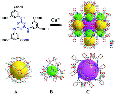 | ||
| Scheme 1 Crystal structure of Cu-TDPAT constructed by H6TDPAT and Cu2+ ions containing three types of cages. | ||
Experimental
Preparation of Cu-TDPAT nanoparticles
The ligand 2,4,6-tris(3,5-dicarboxylphenylamino)-1,3,5-triazine (H6TDPAT) was synthesized according to the ref.36 In the typical procedure, a solution of Cu(NO3)2·3H2O (2.416 g, 10 mmol) and H6TDPAT (1.236 g, 2 mmol) in 150 mL N,N-dimethyl formamide (DMF) was added in a 250 mL round-bottom flask, which was placed in a microwave synthesizer with the power of 400 W and allowed to react for a certain period. After cooling down to room temperature, the product was collected by centrifugation and washed with DMF several times. The reaction times of nano-Cu-TDPAT with the sizes of 100 nm, 200 nm, 500 nm and 1 μm were 2 min, 3 min, 4 min and 5 min, respectively.Preparation of S@Cu-TDPAT
In order to remove the guest solvent in Cu-TDPAT, the powder of Cu-TDPAT was soaked in MeOH for 2 days and then filtered and dried at 60 °C which was further heated at 120 °C under vacuum conditions for 24 h to obtain active Cu-TDPAT. Active Cu-TDPAT and sulfur with the mass ratio of 1![[thin space (1/6-em)]](https://www.rsc.org/images/entities/char_2009.gif) :
:![[thin space (1/6-em)]](https://www.rsc.org/images/entities/char_2009.gif) 1 were mixed by hand-milling and heated through the melt-diffusion method at 155 °C under an Ar atmosphere for 2 h. After cooling to room temperature, the S@Cu-TDPAT cathode materials were collected.
1 were mixed by hand-milling and heated through the melt-diffusion method at 155 °C under an Ar atmosphere for 2 h. After cooling to room temperature, the S@Cu-TDPAT cathode materials were collected.
Battery assembly
80 wt% S@Cu-TDPAT composite, 10 wt% super-P and 10 wt% poly(vinylidene fluoride) (PVDF) binder were mixed in N-methyl-2-pyrrolidone (NMP) to form a slurry. Sonication was used to improve the dispersion. The slurry was then coated on aluminium current collectors as the cathode and dried at 60 °C over 24 h. Coin cells 2032 were assembled in an Ar-filled glovebox (O2, H2O < 0.1 ppm) with an electrolyte of 1.0 M LiTFSI and 0.1 M LiNO3 in DOL/DME (v![[thin space (1/6-em)]](https://www.rsc.org/images/entities/char_2009.gif) :
:![[thin space (1/6-em)]](https://www.rsc.org/images/entities/char_2009.gif) v, 1
v, 1![[thin space (1/6-em)]](https://www.rsc.org/images/entities/char_2009.gif) :
:![[thin space (1/6-em)]](https://www.rsc.org/images/entities/char_2009.gif) 1), a Celgard 2400 membrane, and a Li foil reference anode. For all of the electrochemical tests, the sulfur mass loading was about 1.2 mg cm−2.
1), a Celgard 2400 membrane, and a Li foil reference anode. For all of the electrochemical tests, the sulfur mass loading was about 1.2 mg cm−2.
Characterization
The X-ray powder diffraction patterns were measured on a Bruker D8 Advance diffractometer at 40 kV and 40 mA with a Cu target tube and a graphite monochromator. Thermogravimetric analyses (TGA) were performed on a Netzsch TG 209 F3 Tarsus from room temperature to 800 °C with a heating rate of 10 °C min−1 under flowing nitrogen. The nitrogen physisorption was performed using automatic volumetric adsorption equipment (Belsorp-max); the surface area analysis was based on the Brunauer–Emmett–Teller (BET) theory. SEM morphology and EDS mapping were performed using TESCAN Brno, s.r.o. MIRA3 LMH field-emission scanning electron microscopy (SEM) with an Oxford Instruments NanoAnalysis INCA Energy 150 X-ACT energy dispersive spectrometer (EDS). X-ray photoelectron spectroscopy (XPS) analysis was performed on a Thermo Scientific Escalab 250Xi instrument with Mg Kα radiation (1253.6 eV) at a scan step of 0.1 eV. Galvanostatic charge–discharge cycles were studied using a LAND CT2001A instrument (Wuhan Jinnuo Electronic Co. Ltd) at different C rates (1C = 1680 mA g−1) between 1.8 and 2.8 V (vs. Li+/Li) at room temperature.Computational methods
The preferred sorption locations were searched through Grand Canonical Monte Carlo (GCMC) simulations by using the fixed loading task and the Metropolis method in the sorption calculation module. For all the GCMC simulations, the simulation box was set with 4 (2 × 2 × 1) unit cells while the framework and the polysulfide (Li2Sx, 4 ≤ x ≤ 8) molecules were described using the universal force field (UFF). Both the framework and the polysulfide (Li2Sx, 4 ≤ x ≤ 8) molecules were regarded as rigid models and the QEq partial charges and QEq charges were applied to the atoms of the framework and guest molecules, respectively. The cut off distance was set to 18.5 Å for the Lennard–Jones (LJ) interactions, and the electrostatic interactions and the van der Waals interactions were handled using the Ewald and Atom based summation methods, respectively. The loading steps, equilibration steps and the production steps were all set to 1.0 × 10⁷. The binding energies between MOF and polysulfide (Li2Sx, 4 ≤ x ≤ 8) were calculated using the density functional theory (DFT) within the Perdew–Burke–Ernzerhof generalized gradient approximation (GGA-PBE), as implemented in the Dmol3 package. The double numerical plus polarization (DNP) basis sets with effective core potential were employed to express atomic potentials. Considering the large size of the Cu-TDPAT cell with 960 atoms, as shown in Fig. S10a,† a segment of Cu2(TDPAT)2 containing 104 atoms (Fig. S10b†) was used to model its interaction with polytellurides. The optimized binding configurations with the lowest energy were obtained based on adsorption conformations obtained from GCMC simulation. Self-consistent field calculations were carried out until the SCF tolerance was below 1 × 10⁻⁶. The adsorption energy between the segment of Cu2(TDPAT)2 and adsorbed polysulfide (Li2Sx, 4 ≤ x ≤ 8) is determined using Ea = Eseg. + ELi2Sx − ELi2Sx@seg., where Eseg., ELi2Sx and ELi2Sx@seg. denote the total energies of the segment of Cu2(TDPAT)2, the adsorbed polysulfide, and the polysulfide–segment system, respectively.Results and discussion
As shown in Scheme 1, Cu-TDPAT is constructed using ligand H6TDPAT and the paddle-wheel-like node Cu2(COO)4 with three different kinds of cages in which the nitrogen functional group on ligand H6TDPAT and the axial position of Cu2(COO)4 can provide the adsorption sites for lithium polysulfides (Li2Sx). In Cu-TDPAT, cage A is built by the Cu2(COO)4 nodes and m-phthalic acid, which is similar to the cage structure of HKUST-1; cage B is a tetrahedral cage using four ligands as the wall with the size of 14 Å, while cage C is the largest one adopting eight ligands as the wall to form the octahedral cage with the size of 20.3 Å (Scheme 1). The cage structure with the confined nanospace effect, abundant Cu(II)-OMSs or/and the nitrogen functional sites provides strong assurance for confining the polysulfides and indicates its application as the sulfur carrier in Li–S batteries.Nano-Cu-TDPAT was prepared through microwave synthesis because most of the MOFs perform poorly in electronic and ionic conduction, while reducing the MOF particles may shorten the transport length of both electron and lithium ions and increase the electrode/electrolyte contact area, so as to decrease the internal resistance.37–39 Octahedral nano-Cu-TDPAT with the sizes of ∼100 nm, ∼200 nm, ∼500 nm and ∼1 μm were obtained after the microwave reaction of the mixture of Cu(NO3)2 and H6TDPAT in a DMF solution at the power of 400 W for 2 min, 3 min, 4 min and 5 min respectively (Fig. 1a and S4†). Powder X-ray diffraction indicated that nano-Cu-TDPAT samples with different sizes were all in their pure phase (Fig. 1e). The adsorption isotherms of N2 at 77 K for different sizes of nano-Cu-TDPAT all show typical type I curves for micropores (Fig. S2†). In order to fully confine the sulfur in the MOFs’ pores, it is reasonable to adjust the sulfur loading level according to the micropore volume of the Cu-TDPAT samples, and the sulfur contents of loading for Cu-TDPAT samples with different sizes are all about ∼50% (Table S1†). Here all the Cu-TDPAT samples were loaded with the same quality of sulfur for better comparison with each other. In order to load the sulfur, after being soaked in methanol for 2 days and then activated at 120 °C for 24 h, the Cu-TDPAT samples were manually blended with the sulfur powder at the mass ratio of 1![[thin space (1/6-em)]](https://www.rsc.org/images/entities/char_2009.gif) :
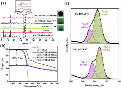
:![[thin space (1/6-em)]](https://www.rsc.org/images/entities/char_2009.gif) 1 and then heated at 155 °C for 2 h to obtain S@Cu-TDPAT. The XRD results (Fig. 2a and S1†) show that the structure of Cu-TDPAT was still maintained well after loading with sulfur while the characteristic peak at about 23.1 degrees of sulfur disappeared in S@Cu-TDPAT indicating that the sulfur was fully adsorbed into the pores of Cu-TDPAT, which was further proved by the N2 adsorption data of Cu-TDPAT and S@CuTDPAT at 77 K (Fig. S2†). Meanwhile, the SEM of S@Cu-TDPAT revealed that after loading with sulfur, S@Cu-TDPAT was still in its octahedral shape and there were no obvious sulfur particles on the surface of MOFs (Fig. S3†). The EDS mapping of S@Cu-TDPAT also indicated that the sulfur was equably loaded in Cu-TDPAT (Fig. S3†). In order to calculate the total loading amount of sulfur, the thermogravimetric analysis of Cu-TDPAT, S and S@Cu-TDPAT was carried out under a nitrogen atmosphere from room temperature to 800 °C. As shown in Fig. 2b, S@Cu-TDPAT experienced two obvious weight loss processes: the first one was from about ∼205 °C to ∼327 °C with a weight loss of about 50% which can be attributed to the sublimation of sulfur in S@Cu-TDPAT; the second one occurred from ∼327 °C to 800 °C which corresponded to the decomposition of MOFs. It is found that the sublimation temperature of sulfur in S@Cu-TDPAT was higher than that of pristine sulfur (about 190 °C) by about 25 °C which implies the interaction between Cu-TDPAT and sulfur in S@Cu-TDPAT. To further illustrate this interaction, the XPS characterization of pristine sulfur and S@Cu-TDPAT was executed and it revealed the obvious chemical shift of S2p spectra in S@Cu-TDPAT compared with that of pristine sulfur, that is from original 164.8 eV to 164.4 eV of S2p1/2 and 163.6 eV to 163.2 eV of S2p3/2 (Fig. 2c). All of these confirm the good interaction between Cu(II)-OMSs in Cu-TDPAT and sulfur, and Cu-TDPAT is a suitable carrier for sulfur to fix it in the cathode so as to improve the cycling performance of Li–S batteries.
1 and then heated at 155 °C for 2 h to obtain S@Cu-TDPAT. The XRD results (Fig. 2a and S1†) show that the structure of Cu-TDPAT was still maintained well after loading with sulfur while the characteristic peak at about 23.1 degrees of sulfur disappeared in S@Cu-TDPAT indicating that the sulfur was fully adsorbed into the pores of Cu-TDPAT, which was further proved by the N2 adsorption data of Cu-TDPAT and S@CuTDPAT at 77 K (Fig. S2†). Meanwhile, the SEM of S@Cu-TDPAT revealed that after loading with sulfur, S@Cu-TDPAT was still in its octahedral shape and there were no obvious sulfur particles on the surface of MOFs (Fig. S3†). The EDS mapping of S@Cu-TDPAT also indicated that the sulfur was equably loaded in Cu-TDPAT (Fig. S3†). In order to calculate the total loading amount of sulfur, the thermogravimetric analysis of Cu-TDPAT, S and S@Cu-TDPAT was carried out under a nitrogen atmosphere from room temperature to 800 °C. As shown in Fig. 2b, S@Cu-TDPAT experienced two obvious weight loss processes: the first one was from about ∼205 °C to ∼327 °C with a weight loss of about 50% which can be attributed to the sublimation of sulfur in S@Cu-TDPAT; the second one occurred from ∼327 °C to 800 °C which corresponded to the decomposition of MOFs. It is found that the sublimation temperature of sulfur in S@Cu-TDPAT was higher than that of pristine sulfur (about 190 °C) by about 25 °C which implies the interaction between Cu-TDPAT and sulfur in S@Cu-TDPAT. To further illustrate this interaction, the XPS characterization of pristine sulfur and S@Cu-TDPAT was executed and it revealed the obvious chemical shift of S2p spectra in S@Cu-TDPAT compared with that of pristine sulfur, that is from original 164.8 eV to 164.4 eV of S2p1/2 and 163.6 eV to 163.2 eV of S2p3/2 (Fig. 2c). All of these confirm the good interaction between Cu(II)-OMSs in Cu-TDPAT and sulfur, and Cu-TDPAT is a suitable carrier for sulfur to fix it in the cathode so as to improve the cycling performance of Li–S batteries.
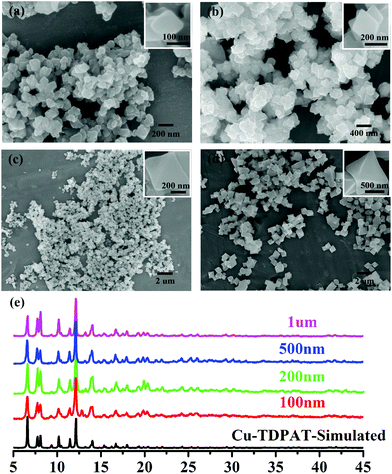 | ||
| Fig. 1 SEM of nano-Cu-TDPAT with different sizes: (a) ∼100 nm; (b) ∼200 nm; (c) ∼500 nm; and (d) ∼1 μm and (e) their corresponding XRD. | ||
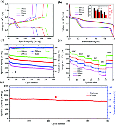
It was reported that the size of nano-MOFs have great impact on the performance of Li–S batteries.34 Hence, Cu-TDPAT samples with different sizes were chosen to prepare S@Cu-TDPAT cathode materials for electrochemical tests. All of S@Cu-TDPAT were assembled into button batteries with lithium as the anode and were galvanostatically charged and discharged at 0.5C (837 mA g−1). As shown in Fig. S7,† the cyclic voltammetry curves of S@Cu-TDPAT composites with different particle sizes all present two cathodic peaks at around ∼2.35 and ∼2.05 V corresponding to the reduction of S8 and soluble long chain polysulfides, respectively, while the two close anodic peaks at around ∼2.35 and ∼2.45 V in the anodic sweep result from the progressive transition of Li2S to lower order polysulfides and higher order polysulfides to elemental sulfur, respectively. Two typical voltage platforms of all S@Cu-TDPAT in Fig. 3a also indicated that the sulfur in S@Cu-TDPAT was discharged from S8 to soluble long chain polysulfides and to Li2S rather than from short sulfur of S2∼4 to Li2S in some reported microporous carbons.40,41 It can be seen clearly that the discharge capacity of the first cycle increased with the decrease of the size of nano-Cu-TDPAT, from 632 mA h g−1 to 995 mA h g−1 under the current of 0.5C. On further exploring the discharge behaviour, it is found that the capacity of QH (the discharge process occurs at a higher voltage corresponding to the reduction of S8 to soluble Li2S4) gradually increases from 186 mA h g−1 to 269 mA h g−1 with the decrease of the size of nano-Cu-TDPAT that is the percentage of sulfur participating in the reaction increases from 44% to 64% and the ratio of the discharge capacity between low voltage and high voltage, QL/QH, was enhanced from 2.40 to 2.68 (Fig. 3a and b). The combination of these phenomena indicates that with the reduction of the size of nano-Cu-TDPAT, the internal sulfur loaded in Cu-TDPAT can be reacted more sufficiently leading to the enhancement of the charge–discharge capacity of the first cycle which is proved by Zhou34 as well. Unlike the case of the conductive hosts such as porous carbon, the electrochemical process would only occur on the external surfaces of the MOF particles, where the active material can get access to both the electron delivering phase (carbon black) and the Li ion delivering phase (electrolyte). The inner sulfur of the MOF particles can only be used after the outer one is reacted completely. So the size of the MOF particles can directly affect the utilization of the sulfur loading in MOFs. The internal sulfur loaded in Cu-TDPAT with a small size can be reacted sufficiently leading to the enhancement of sulfur utilization.
The long-term cycling performance of 300 cycles of S@Cu-TDPAT with different sizes under 0.5C is presented at Fig. 3c. It can be seen that the first cycle capacity and the degree of attenuation over the 300 cycles differed with the size of S@Cu-TDPAT, and the reversible capacities at 0.5C after 300 cycles are 352 mA h g−1 (1 μm), 436 mA h g−1 (500 nm), 631 mA h g−1 (200 nm) and 831 mA h g−1 (100 nm), respectively. Among them, the 100 nm-size S@Cu-TDPAT shows the relatively stable cycling performance and the highest capacity after 300 cycles, which represents the best performance of the reported S@MOF cathode for Li–S batteries so far, compared with the S@NiMOF (about 500 mA h g−1 at 0.2C after 200 cycles), S@ZIF-8 (about 600 mA h g−1 at 0.5C after 250 cycles) and S@MOF-525(Cu) (about 704 mA h g−1 at 0.5C after 200 cycles) (Fig. S9†).30–35 Besides, the ratio performance of different sizes of S@Cu-TDPAT cathodes were studied as well and the 100 nm-size S@Cu-TDPAT also shows better. It is demonstrated that the 100 nm-size S@Cu-TDPAT cathode exhibits capacities of about ∼1000 mA h g−1 at 0.1C, ∼900 mA h g−1 at 0.5C, ∼820 mA h g−1 at 1C, ∼720 mA h g−1 at 2C, and even ∼523 mA h g−1 at 5C, while being restored to ∼948 mA h g−1 as the C-rate switches from 5C to 0.1C. What's more, the 100 nm-size S@Cu-TDPAT cathode delivers good long-term cycling performance even at the current as high as 1C with its capacity stabilizing at about 745 mA h g−1 (298 mA h g−1 based on the whole electrode including binder and electrolyte) after 500 cycles (Fig. 3e and S6†).
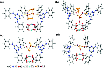
The electrochemical test of the S@Cu-TDPAT cathode indicated that Cu-TDPAT can effectively confine the polysulfides within the pores leading to the high capacity and cycling stability. It is reported that the microporous properties and the polarity of pores in the materials usually could lead to the good adsorption for polysulfides.42,43 For Cu-TDPAT, the type I N2 adsorption isotherms in Fig. S2† confirm its microporosity which contributes to its high adsorption affinity for guest polysulfides. What's more, the OMSs and the N-rich functional group of ligand H6TDPAT render the pore surface rather polar, which also increase the polar–polar interactions with polysulfides in MOFs.31,35,43 In order to understand the binding states of different kinds of polysulfides in Cu-TDPAT, the GCMC and DFT calculations were employed to study the adsorption sites and energy. As shown in Fig. 4, the optimum sorption sites of all the polysulfides are located in the cages containing N-rich ligands (either cage B or cage C) with a similar behavior in Cu-TDPAT. For the polysulfide anions Sx2− (2 ≤ x ≤ 8), in all of the cages the terminal sulfur atom of the chain binds to the Cu2+ ions of the Cu(II)-OMSs which is also reported in other MOFs (Fig. 4 and S7†).32 Regarding the lithium ion, it interacted with the nitrogen functional group in cage B or cage C and we can find that the lithium ion prefers to interact with the secondary amines which may be due to the better coordination between the lone pair electrons of the secondary amine and the lithium ion. What's more, the adsorption energy between polysulfides and Cu-TDPAT was calculated at the same time, and the result showed that Li2S4 and Cu-TDPAT had the strongest interaction (Fig. S12†).
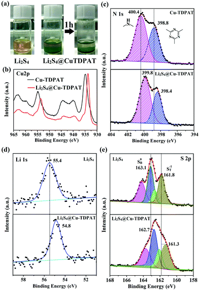
To provide more evidence for the strong interaction between Cu-TDPAT and polysulfides, the activated Cu-TDPAT powder was soaked in the Li2S4/DME solution and it is clear that Cu-TDPAT can completely adsorb the Li2S4 (Fig. 5a). Then Cu-TDPAT adsorbed with Li2S4, Li2S4@Cu-TDPAT, was tested by XPS. The chemical shifts of the Cu2p spectra of Li2S4@Cu-TDPAT to the lower binding energy is clearly observed in Fig. 5b because of the interaction between polysulfide anions and Cu2+ ions. Fig. 5c shows the spectra of N1s. Because there are only two types of nitrogen in Cu-TDPAT, namely secondary-amine nitrogen and pyridine nitrogen, the higher binding energy of 400.4 eV is attributed to the secondary-amine nitrogen and 398.8 eV to the pyridine nitrogen. As shown in Fig. 5c, there are clear N1s chemical shifts of Li2S4@Cu-TDPAT to the lower energy while the chemical shift of secondary-amine nitrogen (0.6 eV) is larger than that of pyridine nitrogen (0.4 eV) which imply that the interaction between secondary-amine nitrogen and lithium is stronger and the result is in accordance with the DFT calculation. The Li1s and S2p chemical shifts to the lower energy in Li2S4@Cu-TDPAT also prove the strong interaction (Fig. 5d and e).
In summary, ligand H6TDPAT with the N-rich functional groups as linkers and the paddle-wheel-like Cu2(COO)4 including Cu(II) open metal sites (OMSs) as nodes were used to develop a bi-functional nano-sized MOF (namely Cu-TDPAT) containing three types of cages A, B, and C for carrying sulfur. Because of the synergistic effect from Lewis acidic sites (central unsaturated CuII ions) binding with polysulfide anions and Lewis basic sites (N atoms in ligand) coordinating to lithium ions as well as the microporous properties, the resultant porous Cu-TDPAT shows excellent confining ability of the polysulfides and effectively inhibits their dissolution and diffusion into the electrolyte. Thus, a high reversible capacity of about 745 mA h g−1 at 1C after 500 cycles was achieved. To the best of our knowledge, it represents the best performance in the currently reported S@MOF cathode materials for MOF-based Li–S batteries.30–35 Clearly, our work provides a good example of designing MOFs with suitable synergistic interaction sites for sulfur and polysulfides to achieve S@MOF cathodes with excellent cycling performance.
Conflicts of interest
There are no conflicts to declare.Acknowledgements
The authors are grateful for the financial aid from the National Natural Science Foundation of P. R. China (Grant No. 21471061 and 21671071), the National Natural Science Foundation of Guangdong Province (Grant No. 2014A030311001 and 2016A030310435), Scientific Research Foundation of Graduate School of South China Normal University (Grant No. 2016lkxm06), Applied Science and Technology Planning Project of Guangdong Province, Guangzhou, China (No. 2015B010135009), Innovation team project of Guangdong Ordinary University (No. 2015KCXTD005), and the great scientific research project of Guangdong Ordinary University (No. 2016KZDXM023).Notes and references
- P. G. Bruce, S. A. Freunberger, L. J. Hardwick and J.-M. Tarascon, Nat. Mater., 2012, 11, 19–29 CrossRef CAS PubMed.
- Z. W. Seh, Y. Sun, Q. Zhang and Y. Cui, Chem. Soc. Rev., 2016, 45, 5605–5634 RSC.
- J. B. Goodenough and Y. Kim, Chem. Mater., 2010, 22, 587–603 CrossRef CAS.
- A. Manthiram, S.-H. Chung and C. Zu, Adv. Mater., 2015, 27, 1980–2006 CrossRef CAS PubMed.
- W. Hua, Z. Yang, H. Nie, Z. Li, J. Yang, Z. Guo, C. Ruan, X. Chen and S. Huang, ACS Nano, 2017, 11, 2209–2218 CrossRef CAS PubMed.
- H. Lin, L. Yang, X. Jiang, G. Li, T. Zhang, Q. Yao, G. W. Zheng and J. Y. Lee, Energy Environ. Sci., 2017, 10, 1476–1486 CAS.
- Y. Pan, Y. Zhou, Q. Zhao, Y. Dou, S. Chou, F. Cheng, J. Chen, H. K. Liu, L. Jiang and S. X. Dou, Nano Energy, 2017, 33, 205–212 CrossRef CAS.
- C. Zhang, H. B. Wu, C. Yuan, Z. Guo and X. W. Lou, Angew. Chem., Int. Ed., 2012, 51, 9592–9595 CrossRef CAS PubMed.
- H. Wang, W. Zhang, H. Liu and Z. Guo, Angew. Chem., Int. Ed., 2016, 55, 3992–3996 CrossRef CAS PubMed.
- Z. Xiao, Z. Yang, L. Zhou, L. Zhang and R. Wang, ACS Appl. Mater. Interfaces, 2017, 9, 18845–18855 CAS.
- Q. Pang, D. Kundu, M. Cuisinier and L. F. Nazar, Nat. Commun., 2014, 5, 4759 CrossRef CAS PubMed.
- T. Zhou, W. Lv, J. Li, G. Zhou, Y. Zhao, S. Fan, B. Liu, B. Li, F. Kang and Q.-H. Yang, Energy Environ. Sci., 2017, 10, 1694–1703 CAS.
- Z. Sun, J. Zhang, L. Yin, G. Hu, R. Fang, H.-M. Cheng and F. Li, Nat. Commun., 2017, 8, 14627 CrossRef PubMed.
- X. Liu, J. Q. Huang, Q. Zhang and L. Mai, Adv. Mater., 2017, 29, 1601759 CrossRef PubMed.
- Z. Li, J. Zhang and X. W. Lou, Angew. Chem., Int. Ed., 2015, 54, 12886–12890 CrossRef CAS PubMed.
- K. Liao, P. Mao, N. Li, M. Han, J. Yi, P. He, Y. Sun and H. Zhou, J. Mater. Chem. A, 2016, 4, 5406–5409 CAS.
- Q. Pang and L. F. Nazar, ACS Nano, 2016, 10, 4111–4118 CrossRef CAS PubMed.
- Z. Xiao, Z. Yang, L. Zhang, H. Pan and R. Wang, ACS Nano, 2017, 11, 8488–8498 CrossRef CAS PubMed.
- H. Wang, T. Zhou, D. Li, H. Gao, G. Gao, A. Du, H. Liu and Z. Guo, ACS Appl. Mater. Interfaces, 2017, 9, 4320–4325 CAS.
- K. Mi, S. Chen, B. Xi, S. Kai, Y. Jiang, J. Feng, Y. Qian and S. Xiong, Adv. Funct. Mater., 2017, 27, 1604265 CrossRef.
- X. Chen, Z. Wang, R. Zhang, L. Xu and D. Sun, Chem. Commun., 2017, 53, 10560–10563 RSC.
- F. Wang, H.-Y. Zhuo, X. Han, W.-M. Chen and D. Sun, J. Mater. Chem. A, 2017, 5, 13079–13085 Search PubMed.
- P.-Q. Liao, N.-Y. Huang, W.-X. Zhang, J.-P. Zhang and X.-M. Chen, Science, 2017, 356, 1193–1196 CrossRef CAS PubMed.
- J. Liu, L. Chen, H. Cui, J. Zhang, L. Zhang and C. Y. Su, Chem. Soc. Rev., 2014, 43, 6011–6061 RSC.
- Z. Hu, B. J. Deibert and J. Li, Chem. Soc. Rev., 2014, 43, 5815–5840 RSC.
- J. Liu, D. Zhu, C. Guo, A. Vasileff and S.-Z. Qiao, Adv. Energy Mater., 2017 DOI:10.1002/aenm.201700518.
- Z. Bai, Y. Zhang, Y. Zhang, C. Guo, B. Tang and D. Sun, J. Mater. Chem. A, 2015, 3, 5266–5269 CAS.
- X. Han, W.-M. Chen, X. Han, Y.-Z. Tan and D. Sun, J. Mater. Chem. A, 2016, 4, 13040–13045 CAS.
- W.-M. Chen, X.-L. Meng, G.-L. Zhuang, Z. Wang, M. Kurmoo, Q.-Q. Zhao, X.-P. Wang, B. Shan, C.-H. Tung and D. Sun, J. Mater. Chem. A, 2017, 5, 13079–13085 CAS.
- R. Demir-Cakan, M. Morcrette, F. Nouar, C. Davoisne, T. Devic, D. Gonbeau, R. Dominko, C. Serre, G. Ferey and J. M. Tarascon, J. Am. Chem. Soc., 2011, 133, 16154–16160 CrossRef CAS PubMed.
- J. Zheng, J. Tian, D. Wu, M. Gu, W. Xu, C. Wang, F. Gao, M. H. Engelhard, J. G. Zhang, J. Liu and J. Xiao, Nano Lett., 2014, 14, 2345–2352 CrossRef CAS PubMed.
- J. Zhou, R. Li, X. Fan, Y. Chen, R. Han, W. Li, J. Zheng, B. Wang and X. Li, Energy Environ. Sci., 2014, 7, 2715 CAS.
- Z. Zhao, S. Wang, R. Liang, Z. Li, Z. Shi and G. Chen, J. Mater. Chem. A, 2014, 2, 13509–13512 CAS.
- J. Zhou, X. Yu, X. Fan, X. Wang, H. Li, Y. Zhang, W. Li, J. Zheng, B. Wang and X. Li, J. Mater. Chem. A, 2015, 3, 8272–8275 CAS.
- Z. Wang, B. Wang, Y. Yang, Y. Cui, Z. Wang, B. Chen and G. Qian, ACS Appl. Mater. Interfaces, 2015, 7, 20999–21004 CAS.
- B. Li, Z. Zhang, Y. Li, K. Yao, Y. Zhu, Z. Deng, F. Yang, X. Zhou, G. Li, H. Wu, N. Nijem, Y. J. Chabal, Z. Lai, Y. Han, Z. Shi, S. Feng and J. Li, Angew. Chem., Int. Ed., 2012, 51, 1412–1415 CrossRef CAS PubMed.
- J. Zhu, Y. K. Sharma, Z. Zeng, X. Zhang, M. Srinivasan, S. Mhaisalkar, H. Zhang, H. H. Hng and Q. Yan, J. Phys. Chem. C, 2011, 115, 8400–8406 CAS.
- J. G. Kang, Y. D. Ko and J. G. Park, Nanoscale Res. Lett., 2008, 3, 390–394 CrossRef CAS.
- C.-T. Hsieh, J.-S. Lin, Y.-F. Chen and H. Teng, J. Phys. Chem. C, 2012, 116, 15251–15258 CAS.
- Z. Li, Y. Jiang, L. Yuan, Z. Yi, C. Wu, Y. Liu, P. Strasser and Y. Huang, ACS Nano, 2014, 8, 9295–9303 CrossRef CAS PubMed.
- Z. Li and L. Yin, ACS Appl. Mater. Interfaces, 2015, 7, 4029–4038 CAS.
- F. Hippauf, W. Nickel, G.-P. Hao, K. Schwedtmann, L. Giebeler, S. Oswald, L. Borchardt, S. Doerfler, J. J. Weigand and S. Kaskel, Adv. Mater. Interfaces, 2016, 3, 1600508 CrossRef.
- G.-P. Hao, C. Tang, E. Zhang, P. Zhai, J. Yin, W. Zhu, Q. Zhang and S. Kaskel, Adv. Mater., 2017, 29, 1702829 CrossRef PubMed.
Footnote |
| † Electronic supplementary information (ESI) available. See DOI: 10.1039/c7nr07118c |
| This journal is © The Royal Society of Chemistry 2018 |

