 Open Access Article
An improved Hummers method derived graphene oxide wrapped ZIF-8 polyhedron derived porous heterostructure for symmetric supercapacitor performance†
Rahul
Patil‡
 a,
Nitish
Kumar‡
 b,
Babasahab
Matsagar
 c,
Kevin C. W.
Wu
 cd,
Rahul R.
Salunkhe
 *b and
Saikat
Dutta
 *a
*a
aElectrochemical Energy & Sensor Research Laboratory, Amity Institute of Click Chemistry Research and Studies, Amity University Noida, Uttar Pradesh 201313, India. E-mail: sdutta2@amity.edu
bMaterials Research Laboratory, Department of Physics, Indian Institute of Technology Jammu, NH-44, Jammu, 181221, Jammu and Kashmir, India
cDepartment of Chemical Engineering, National Taiwan University, No. 1, Sec. 4, Roosevelt Road, Taipei 10617, Taiwan
dDepartment of Chemical Engineering and Materials Science, Yuan Ze University, Chung-Li, Taoyuan, Taiwan
First published on 21st November 2023
Abstract
Heterostructure materials are intriguing because they may combine two or more building blocks that produce novel heterointerfaces with exceptional features. By exposing more interfaces and active sites, their utility in electrochemical applications is further expanded when they are used to form large-scale 3D frameworks. This study uses improved graphene oxide (IGO) and GO to form a heterojunction (ZIF-8/IGO). The interface between ZIF-8 and IGO accelerated the transfer of thermally obtained electrons from ZIF-8-NC to IGO. We focus on developing a 2D heterostructure mixed porous system based on differences in the density of oxygen-containing functional groups of improved graphene oxide (IGO) and commercially accessed graphene oxide (GO) while forming a composite with ZIF-8. IGO@ZIF-8-NC exhibited a very high capacitance of 352.8 F g−1 as compared to 287.5 F g−1 for GO@ZIF-8-NC at a scan rate of 5 mV s−1 confirming that the former is an excellent supercapacitor electrode owing to the synergistic behaviour at the heterojunction interface. The results on IGO-based electrodes pave the way forward for sustainable capacitive devices.
Sustainability spotlightThe capacitor technology opens the opportunity for very cost-effective and environmentally sustainable power devices. We are interested in finding out how an enhanced graphene oxide preparation would boost the efficiency of a capacitor device compared to conventionally prepared graphene oxide. IGO@ZIF-8-NC exhibited a very high capacitance of 352.8 F g−1 as compared to 287.5 F g−1 for GO@ZIF-8-NC at a scan rate of 5 mV s−1 confirming that the former is an excellent supercapacitor electrode owing to the synergistic behaviour at the heterojunction interface. These results reveal the effect of the heterojunction interface associated with improved graphene oxide for highlighting its application in sustainable capacitance devices. This report also establishes an effective link between sustainable IGO preparation and capacitance-enhanced devices. |
1 Introduction
Heterostructured materials combine two building blocks with a heterointerface, which can be engineered to modulate internal electric fields by combining the advantages of each component, and this may offer outstanding new synergistic properties in the case of 2 and 3-dimensional materials. Interfacial compatibility of graphene oxide and ZIF-8-derived N-doped carbon frameworks based on the nature and strength of interactions, surface coverage, and conformation of graphene oxide (GO) at the zeolitic imidazolate framework (ZIF-8) derived NC surface requires a fundamental understanding for an optimal composite of GO/ZIF-8NC with high mechanical resilience. Majorly, atomistic representations of the functionalized GO integrating the nature and concentration of the functionalized groups of GO (e.g. epoxy, hydroxyl, carboxylate) result in a suitable model for the resulting ZIF-8NC/GO interface, which is a scenario similar to pristine GO composites.1 What level of distortion of the first GO layer brought in contact with the ZIF-8-NC leads to an interfacial region with an altered width wherein functional groups of GO (e.g. epoxy, hydroxyl, carboxylic) play an essential role towards forming a defect free interface.22D heterostructured materials are one nanohybrid with ordered mesoporous and microporous carbon which can prevent restacking of 2D microporous nanosheets and boost the number of ion-accessible surfaces and facilitate rapid transport of electrons and ions.3 A long range of interfacial properties in the hierarchical interfaces for multiscale control of electrical properties. The composite carries unique superwettability and abundant meso/microporosity toward rapid rates of electron transfer.4 GO is a 2D carbon nanosheet with abundant oxygen-containing groups on the exposed surface and wide use results in graphene-based 2D heterostructured architecture containing varied porosity profiles. Such heterostructured graphene composites bring together the advantages of high conductivity and good electrochemical stability from graphene and mesoporous porosity profiles. Therefore, 3D carbon materials can be formed by using ZIF-8 well-dispersed on GO to result in composite 2D heterostructure nanosheets with better ion-accessible surface areas with advantages including faster electron transport. Generally, such 2D heterostructured nanosheets are fabricated via assembly of the carbon source (e.g. metal–organic framework) on the surfaces of 2D building blocks with challenges for scaling up the resulting 3D porous architectures with heterostructured interfaces.5
Graphene/ZIF-8 nanocomposites exhibit tunable hierarchical porosity and surface areas with a good distribution of micro and mesopores along the size of ZIF-8-derived N-doped frameworks by varying the annealing temperature of graphene oxide 2-dimensional sheets.6 Investigations revealed that ZIF-8 could prevent the stacking of GO sheets which act as anchoring supports by enabling uniformity in the particle size distribution of the ZIF-8 framework by avoiding their aggregation.7In situ 3D assembly of reduced graphene oxide (rGO)/ZIF-67 leads to multifarious affinity interactions consisting of synergistic interactions mainly driven by π–π interactions and electrostatic interactions at the interface.8 A significantly hydrophilic oxidized graphene material is known as accessible via a modified and improved Hummers method which focuses on the need for improved synthesis of GO with high electrical conductivity.9 It is also realized that a preferential orientation of the substrate on GO/ZIF-8NC where in random orientation cannot be ruled out.10
Herein, we focus on developing a 2D heterostructure mixed porous system based on differences in the density of oxygen-containing functional groups of improved graphene oxide (IGO) and commercially accessed graphene oxide (GO) while forming a composite with ZIF-8. Therefore, we aimed to achieve a uniform coating of ZIF-8 on the IGO and GO surfaces to result in IGO@ZIF-8 and GO@ZIF-8. These samples were carbonized and washed with HCl to result in layered heterostructured carbons with components of the reduced graphene oxide (rGO)-based nanoporous N-doped carbon (NC) containing ZIF-8 framework structure. The IGO@ZIF-8-NC exhibited a very high capacitance of 352.8 F g−1 as compared to 287.5 F g−1 for GO@ZIF-8-NC at a scan rate of 5 mV s−1. The IGO@ZIF-8-NC material is an excellent supercapacitor electrode material owing to the synergistic behavior at the interface of IGO and the ZIF-8-derived carbon.
2 Results and discussion
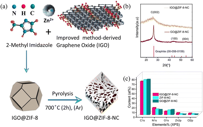
A composite of IGO with ZIF-8 was obtained via a hydrothermal method followed by pyrolysis under argon at 700 °C (Fig. 1(a)). The XRD pattern exhibits a known peak located at 25° which corresponds to the (002) peak of the graphitic structure rather than GO@ZIF-8-NC (Fig. 1(b)). IGO@ZIF-8-NC demonstrates the same pattern as in the case of GO@ZIF-8-NC however, the nature of carbon is amorphous in IGO@ZIF-8-NC. A recent report suggested a metal–support interaction with an amorphous support to provide high stability and activity.11 Nanoporous NC prepared from ZIF-8 crystals has a relatively high N content of ∼16 wt% but the carbon is in an amorphous state.12 The XRD of IGO@ZIF-8 shows that it is amorphous due to the higher percentage of Zn ions in the IGO@ZIF-8-NC (Table S1†). Fig. 1(c) presents the elemental atomic content of each element in samples IGO@ZIF-8-NC and GO@ZIF-8-NC, which are compared with ZIF-8-NC based on Table S1† results calculated from XPS survey spectra. Brunauer–Emmett–Teller (BET) surface analysis of IGO@ZIF-8-NC reveals a surface area of 343 m2 g−1 (Fig. S1(a)†) however, GO@ZIF-8-NC shows a reduced surface area of 263 m2 g−1 (Fig. S1(b)†). Pore profile analysis (Fig. S1(c)†) shows microporous architecture in both materials, which originates from the ZIF-8 microporous framework. Raman spectral analysis (Fig. S1(d)†) confirms the presence of D and G bands confirming the graphitic nature of the composites. Table 1 shows the comparison of the surface parameters of IGO@ZIF-8-NC, GO@ZIF-8-NC, and ZIF-8-NC.| Material | Specific surface area (m2 g−1) | Total pore volume (cm3 g−1) | Mean pore diameter (nm) |
|---|---|---|---|
| GO@ZIF-8-NC | 275.4 | 0.135 | 2.31 |
| IGO@ZIF-8-NC | 343.1 | 0.318 | 3.70 |
| ZIF-8-NC | 551.40 | 0.252 | 1.98 |
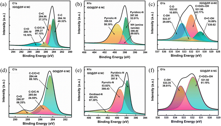
Deconvolution of C 1s of IGO@ZIF-8-NC indicates four peaks associated with the peak positions of C1 (284.16 eV, C![[double bond, length as m-dash]](https://www.rsc.org/images/entities/char_e001.gif) C, sp2 40.3%), C2 (284.96, C–C, sp3, 37.3%), C3 (285, C–N/C–O 7.15%), and C4 (288.1, C(O)–O) (Fig. 2(a)). The N 1s enlarged scan features the peaks of N1 corresponding to pyridinic-N (397.8 eV), N2 corresponding to quaternary, and graphitic N (399.5) corresponding to pyrrolic-N, with a minimum percentage of amine/amide (NH) (398.4 eV) (Fig. 2(b)). Moreover, O 1s spectra show four peaks of C(O)–OH (530.62), C
C, sp2 40.3%), C2 (284.96, C–C, sp3, 37.3%), C3 (285, C–N/C–O 7.15%), and C4 (288.1, C(O)–O) (Fig. 2(a)). The N 1s enlarged scan features the peaks of N1 corresponding to pyridinic-N (397.8 eV), N2 corresponding to quaternary, and graphitic N (399.5) corresponding to pyrrolic-N, with a minimum percentage of amine/amide (NH) (398.4 eV) (Fig. 2(b)). Moreover, O 1s spectra show four peaks of C(O)–OH (530.62), C![[double bond, length as m-dash]](https://www.rsc.org/images/entities/char_e001.gif) O (Zn–OH/C
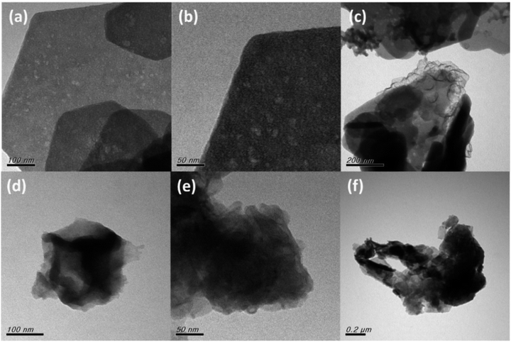
O (Zn–OH/C![[double bond, length as m-dash]](https://www.rsc.org/images/entities/char_e001.gif) O), C–O (532.62) and C–OH (533.37) (Fig. 2(c)). Similar trends are observed for GO@ZIF-8 (Fig. 2(d–f)). Transmission electron microscopy analysis reveals a structural pattern of IGO@ZIF-8-NC exhibiting an intact framework of ZIF-8 in the 2D graphene surface such as in Fig. 3(a) and (b). At a scale of 200 nm, ZIF-8-NC microparticles are evident on the IGO surface (Fig. 3(c)). The formation of GO@ZIF-8-NC is shown in Fig. 3(d) which is further confirmed via the uniform distribution of ZIF-8-NC nanoparticles over the GO surface (Fig. 3(e) and (f)).
O), C–O (532.62) and C–OH (533.37) (Fig. 2(c)). Similar trends are observed for GO@ZIF-8 (Fig. 2(d–f)). Transmission electron microscopy analysis reveals a structural pattern of IGO@ZIF-8-NC exhibiting an intact framework of ZIF-8 in the 2D graphene surface such as in Fig. 3(a) and (b). At a scale of 200 nm, ZIF-8-NC microparticles are evident on the IGO surface (Fig. 3(c)). The formation of GO@ZIF-8-NC is shown in Fig. 3(d) which is further confirmed via the uniform distribution of ZIF-8-NC nanoparticles over the GO surface (Fig. 3(e) and (f)).
 | ||
| Fig. 2 XPS spectra (a) C 1s, (b) N 1s, and (c) O 1s for IGO@ZIF-8 NC and (d) C 1s, (e) N 1s, and (f) O 1s GO@ZIF-8-NC. | ||
 | ||
| Fig. 3 Transmission electron micrographs of (a) IGO@ZIF-8-NC 100 nm, (b) 50 nm, and (c) 200 nm, and (d) GO@ZIF-8-NC 100 nm, (e) 50 nm, and (f) 0.2 μm. | ||
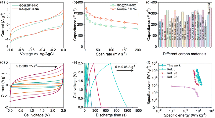
Motivated by the excellent physicochemical properties of both samples, we tested them in a three-electrode configuration for supercapacitor application. We have used a graphite electrode of dimension 1 cm2 for coating the active material over it. The Ag/AgCl reference electrode and Pt wire counter electrode were used in 3 M KOH electrolyte.19 The voltage window was finalized from −1 to 0 V, and both materials were tested at different scan rates varying from 5 to 200 mV s−1 (Fig. S4†). The comparative CV profiles for both samples at a scan rate of 10 mV s−1 are shown in Fig. 4(a). The IGO@ZIF-8-NC sample exhibited a more enclosed area under the CV curve, explaining its improved electrochemical activity.21 Further, the comparative capacitance values at different scan rates for both materials are displayed in Fig. 4(b). The IGO@ZIF-8-NC exhibited a very high capacitance of 352.8 F g−1 compared to 287.5 F g−1 for GO@ZIF-8-NC at a scan rate of 5 mV s−1. Although these values are significantly higher than those of the previously reported carbon-based materials, in particular the IGO@ZIF-8-NC sample outclasses most of the reported carbon materials derived from different MOFs and MOF composites, as shown in Fig. 4(c) and Table S2.†
 | ||
| Fig. 4 Electrochemical testing of GO@ZIF-8-NC and IGO@ZIF-8-NC samples. (a) Comparative CV profiles in three-electrode testing at 10 mV s−1. (b) The capacitance with the scan rate curves for GO@ZIF-8-NC and IGO@ZIF-8-NC samples. (c) Three electrode capacitance value comparison with the previously reported literature.2–20 (d) Two electrode-packed cell CV curves at different scan rates for IGO@ZIF-8-NC. (e) GCD curves at current densities varying from 0.05 A g−1 to 5 A g−1. (f) Ragone plot comparing our device performance with the previously reported different carbon-based supercapacitors. | ||
Based on the three-electrode performance, the IGO@ZIF-8-NC material was further utilized for the packed two-electrode study. The active material was coated over the carbon cloth, and then packed in a symmetric configuration using Whatmann filter paper as the separator and 1 M tetraethyl ammonium tetrafluoroborate in acetonitrile as the electrolyte. The voltage window for the device was finalized by obtaining CV curves at 100 mV s−1 at different voltages varying from 1 V to 3 V, as displayed in Fig. S4(a).† Irreversible changes can be observed for voltages above 2.6 V; hence, 2.5 V was fixed as the working voltage for the detailed study of the device. The CV curves at different scan rates for the assembled symmetric supercapacitor device (SSD) are shown in Fig. 4(d). As anticipated, the device exhibited a nearly rectangular CV shape, indicating that most of the charge is being stored by the electrostatic adsorption–desorption of electrolyte ions. Further, galvanostatic charge–discharge (GCD) curves at different current densities, namely, 0.05, 0.1, 0.2, 0.3, 0.5, 1, 3, and 5 A g−1 are displayed in Fig. 4(e). The device capacitance versus current density plot is shown in Fig. S4(b).† Based on the capacitance values calculated from GCD curves, the specific energy (SE) and specific power (SP) values were calculated and plotted over the Ragone plot. The comparison of different MOF-derived carbon materials for SSDs with our device is shown over the Ragone plot in Fig. 4(f). These reported materials include graphene-mesoporous carbon, ZIF-8 derived porous carbon,22 and ZIF-67 derived porous carbon.3,23 Interestingly, our device exhibited a maximum SE value of 16.3 W h kg−1 with a maximum SP of 12![[thin space (1/6-em)]](https://www.rsc.org/images/entities/char_2009.gif) 500 W kg−1. Thus, the IGO@ZIF-8-NC material is an excellent supercapacitor electrode material owing to the synergistic behavior of IGO and the ZIF-8-derived carbon. The IGO@ZIF-8-NC device was tested for 10
500 W kg−1. Thus, the IGO@ZIF-8-NC material is an excellent supercapacitor electrode material owing to the synergistic behavior of IGO and the ZIF-8-derived carbon. The IGO@ZIF-8-NC device was tested for 10![[thin space (1/6-em)]](https://www.rsc.org/images/entities/char_2009.gif) 000 charge–discharge cycles. Throughout the cycling test, the device showed a coulombic efficiency of >95% and a cyclic retention of about 84% (Fig. S5†). It has been witnessed that selective growth of ZIF-8 in the microporous defects enlarges the interlayer spacings giving mechanical integrity to the composite framework with a stable microstructure. Such microporous pore architecture in IGO@ZIF-8-NC may act more efficiently as compared to GO@ZIF-7-NC.24 In enhancing supercapacitance, short electrolyte diffusion channels as well as electron transport distance would effectively reduce the volume changes of electrode materials during the capacitance storing charge–discharge process. Sluggish reaction dynamics and poor structural stability of capacitance electrodes caused by the insertion/extraction of ions inhibit the potential of the energy storage system.25–27 The chemically synthesized multi-component capacitance electrode widens into vivid nanostructures for specific capacity, energy, power density, rate capability and cycling stability.28–31 With the above reported results, an attempt is made to obtain an insightful understanding on the role of the graphene structure in ZIF-8-derived surfaces.
000 charge–discharge cycles. Throughout the cycling test, the device showed a coulombic efficiency of >95% and a cyclic retention of about 84% (Fig. S5†). It has been witnessed that selective growth of ZIF-8 in the microporous defects enlarges the interlayer spacings giving mechanical integrity to the composite framework with a stable microstructure. Such microporous pore architecture in IGO@ZIF-8-NC may act more efficiently as compared to GO@ZIF-7-NC.24 In enhancing supercapacitance, short electrolyte diffusion channels as well as electron transport distance would effectively reduce the volume changes of electrode materials during the capacitance storing charge–discharge process. Sluggish reaction dynamics and poor structural stability of capacitance electrodes caused by the insertion/extraction of ions inhibit the potential of the energy storage system.25–27 The chemically synthesized multi-component capacitance electrode widens into vivid nanostructures for specific capacity, energy, power density, rate capability and cycling stability.28–31 With the above reported results, an attempt is made to obtain an insightful understanding on the role of the graphene structure in ZIF-8-derived surfaces.
In conclusion, a hierarchical heterointerface was accessed by fabricating IGO@ZIF-8-NC, which was compared with GO@ZIF-8-NC. The highly hydrophobic nature of the heterointerface material IGO@ZIF-8-NC affords accelerated electron conduction and ion diffusion to result in a higher capacitance of 352.8 F g−1 compared to 287.5 F g−1 for GO@ZIF-8-NC at a scan rate of 5 mV s−1. The assembled symmetric supercapacitor device (SSD) exhibited a nearly rectangular CV shape, indicating that most of the charge is being stored by the electrostatic adsorption–desorption of electrolyte ions. The device capacitance versus current density plot and the specific energy (SE) and specific power (SP) values calculated based on the capacitance values obtained from GCD curves support the device design for further light-emitting diode applications.
Conflicts of interest
There are no conflicts to declare.Acknowledgements
SD wishes to acknowledge research funding support by the Department of Biotechnology, Ministry of Science & Technology, Government of India for the grant number BT/RLF/Re-entry/41/2017 under a DBT Ramalingaswami Re-entry Fellowship (2019–2024) and DBT-Energybioscience-Biofuels research grant (2022–2025 BT/PR38594/PBD/26/795/2020). KCW is thankful to the National Science and Technology Council (NSTC), Taiwan (111-2124-M-002-021 and 111-2628-E-002-008) for the funding support. Also, financial support by the Center of Atomic Initiative for New Materials, National Taiwan University, from the Featured Areas Research Center Program within the framework of the Higher Education Sprout Project by the Ministry of Education in Taiwan (111L900801), is acknowledged.References
- D. C. Marcano, D. V. Kosynkin, J. M. Berlin, A. Sinitskii, Z. Sun, A. Slesarev, L. B. Alemany, W. Lu and J. M. Tour, ACS Nano, 2010, 4, 4806–4814 CrossRef CAS.
- P. Zhang, F. Sun, Z. Shen and D. Cao, J. Mater. Chem. A, 2014, 2, 12873–12880 RSC.
- R. R. Salunkhe, Y. Kamachi, N. L. Torad, S. M. Hwang, Z. Sun, S. X. Dou, J. H. Kim and Y. Yamauchi, J. Mater. Chem. A, 2014, 2, 19848–19854 RSC.
- S. Zhong, C. Zhan and D. Cao, Carbon, 2015, 85, 51–59 CrossRef CAS.
- W. Bao, A. K. Mondal, J. Xu, C. Wang, D. Su and G. Wang, J. Power Sources, 2016, 325, 286–291 CrossRef CAS.
- Y. Liu, J. Xu and S. Liu, Microporous Mesoporous Mater., 2016, 236, 94–99 CrossRef CAS.
- R. Patil, N. Kumar, S. Bhattacharjee, B. M. Matsagar, P. C. Han, K. C. W. Wu, R. R. Salunkhe, A. Bhaumik and S. Dutta, Mater. Today Chem., 2023, 28, 101374 CrossRef CAS.
- C. Wang, C. Liu, J. Li, X. Sun, J. Shen, W. Han and L. Wang, Chem. Commun., 2017, 53, 1751–1754 RSC.
- K. Zhao, S. Liu, G. Ye, Q. Gan, Z. Zhou and Z. He, J. Mater. Chem. A, 2018, 6, 2166–2175 RSC.
- R. Patil, N. Kumar, S. Bhattacharjee, H.-Y. Wu, P.-C. Han, B. M. Matsagar, K. C. W. Wu, R. R. Salunkhe, A. Bhaumik and S. Dutta, Chem. Eng. J., 2023, 453, 139874 CrossRef CAS.
- D. Zhang, J. Wang, Q. Wang, S. Huang, H. Feng and H. Luo, J. Energy Storage, 2019, 25, 100904 CrossRef.
- W. Kukulka, K. Cendrowski and E. Mijowska, Electrochim. Acta, 2019, 307, 582–594 CrossRef CAS.
- J. Kim, C. Young, J. Lee, M.-S. Park, M. Shahabuddin, Y. Yamauchi and J. H. Kim, Chem. Commun., 2016, 52, 13016–13019 RSC.
- J. Hu, H. Wang, Q. Gao and H. Guo, Carbon, 2010, 48, 3599–3606 CrossRef CAS.
- P. Wen, Z. Li, P. Gong, J. Sun, J. Wang and S. Yang, RSC Adv., 2016, 6, 13264–13271 RSC.
- Y. Wang, B. Chen, Y. Zhang, L. Fu, Y. Zhu, L. Zhang and Y. Wu, Electrochim. Acta, 2016, 213, 260–269 CrossRef CAS.
- I. A. Khan, A. Badshah, I. Khan, D. Zhao and M. A. Nadeem, Microporous Mesoporous Mater., 2017, 253, 169–176 CrossRef.
- J. Huang, F. Hao, X. Zhang and J. Chen, J. Electroanal. Chem., 2018, 810, 86–94 CrossRef CAS.
- N. Kumar, N. Bansal, Y. Yamauchi and R. R. Salunkhe, Chem. Mater., 2022, 34, 4946–4954 CrossRef CAS.
- P. Pachfule, D. Shinde, M. Majumder and Q. Xu, Nat. Chem., 2016, 8, 718–724 CrossRef CAS PubMed.
- N. Kumar, N. Bansal and R. R. Salunkhe, Chem. Commun., 2021, 57, 13748–13751 RSC.
- D. Zhang, X. Wen, L. Shi, T. Yan and J. Zhang, Nanoscale, 2012, 4, 5440–5446 RSC.
- N. Kumar, T. A. Wani, P. K. Pathak, A. Bera and R. R. Salunkhe, Sustainable Energy Fuels, 2022, 6, 1762–1769 RSC.
- W.-H. Zhang, M.-J. Yin, Q. Zhao, C.-G. Jin, N. Wang, S. Ji, C. L. Ritt, M. Elimelech and Q.-F. An, Nat. Nanotechnol., 2021, 16, 337–343 CrossRef CAS PubMed.
- S. Liu, L. Kang, J. Henzie, J. Zhang, J. Ha, M. A. Amin, M. S. A. Hossain, S. C. Jun and Y. Yamauchi, ACS Nano, 2021, 15, 18931–18973 CrossRef CAS.
- S. Liu, L. Kang and S. C. Jun, Adv. Mater., 2021, 33, 2004689 CrossRef CAS PubMed.
- S. Liu, Y. Yin, D. Ni, K. S. Hui, M. Ma, S. Park, K. N. Hui, C.-Y. Ouyang and S. C. Jun, Energy Storage Mater., 2019, 22, 384–396 CrossRef.
- R. S. Redekar, A. T. Avatare, J. L. Chouhan, K. V. Patil, O. Y. Pawar, S. L. Patil, A. A. Bhoite, V. L. Patil, P. S. Patil and N. L. Tarwal, Chem. Eng. J., 2022, 450, 137425 CrossRef CAS.
- A. A. Bhoite, K. V. Patil, R. S. Redekar, P. S. Patil, V. A. Sawant and N. L. Tarwal, J. Solid State Chem., 2023, 326, 124192 CrossRef CAS.
- X. Zheng, X. Yan, Y. Sun, Z. Bai, G. Zhang, Y. Shen, Q. Liang and Y. Zhang, ACS Appl. Mater. Interfaces, 2015, 7, 2480–2485 CrossRef CAS PubMed.
- S. P. Gupta, V. B. Patil, N. L. Tarwal, S. D. Bhame, S. W. Gosavi, I. S. Mulla, D. J. Late, S. S. Suryavanshi and P. S. Walke, Mater. Chem. Phys., 2019, 225, 192–199 CrossRef CAS.
Footnotes |
| † Electronic supplementary information (ESI) available. See DOI: https://doi.org/10.1039/d3su00327b |
| ‡ Equal contribution from the first two authors. |
| This journal is © The Royal Society of Chemistry 2024 |

