 Open Access Article
 This Open Access Article is licensed under a
 Creative Commons Attribution 3.0 Unported Licence
On-surface chemical dynamics of monolayer, bilayer, and many-layered graphene surfaces probed with supersonic beam scattering and STM imaging
Joshua
Wagner
 ,
Ross
Edel
,
Tim
Grabnic
,
Bryan
Wiggins
and
Steven J.
Sibener
*
,
Ross
Edel
,
Tim
Grabnic
,
Bryan
Wiggins
and
Steven J.
Sibener
*
The James Franck Institute and Department of Chemistry, The University of Chicago, 929 East 57th Street, Chicago, IL 60637, USA. E-mail: s-sibener@uchicago.edu
First published on 21st February 2024
Abstract
We have developed the capability to elucidate interfacial reaction dynamics using an arguably unique combination of supersonic molecular beams combined with in situ STM visualization. These capabilities have been implemented in order to reveal the complex spatiotemporal correlations that govern the oxidation of graphitic systems spanning atomic-, nano-, and meso-length scales. In this study, the 3 nm periodic moiré pattern of monolayer and bilayer graphene on Ru(0001) provides a diverse palette of potential scattering and binding sites at the interface for ground state atomic oxygen. We resolve the site-specificity of atomic oxygen placement on the moiré lattice for both monolayer and bilayer graphene on Ru(0001) with atomic resolution. Angle- and energy-controlled scattering of O(3P) on these interfaces reveals an incisive side-by-side comparison of preferential reactivity of the monolayer surface compared to a more free-standing bilayer graphene ruthenium interface. Morphologically dependent reactivity of many layered graphene (HOPG) and monolayer graphene on Ru(0001) reveal anisotropic on-surface reactivity dependent on the presence of proximal reacted sites or local regions. The kinetics of on-surface oxidation are additionally shown to influence the morphology of surface products by varying the temperature of the interface and flux of reactant species. Such correlations are important in chemisorption, catalysis, materials oxidation and erosion, and film processing—and tunable moiré templated adsorption is a route to well-ordered self-assembled 2D materials for use in next-generation platforms for quantum devices and catalysis. Taken together, these results highlight a new direction in the examination of interfacial reaction dynamics where incident beam kinetic energy and angle of incidence can be used as reaction control parameters, with outcomes such as site-specific reactivity, changes for overall time-evolving mechanisms, and the relative importance of non-adiabatic channels in adsorption all linked to the on-surface fate of chemisorbed species.
Introduction
Surface scattering techniques have been developed with increasing instrumental ingenuity and complexity to track the heterogeneous chemical dynamics pertinent to catalysis, surface passivation, astrochemistry, and a myriad of different applications.1–14 Many novel and traditional techniques excel at examining volatile products or ensemble measurements of adsorbed surface species; however, such methods fail to capture spatiotemporal correlations that evolve under non-equilibrium conditions. In this paper, we present experiments on the oxidation of monolayer, bilayer, and multilayer graphene that directly measure on-surface reaction dynamics and provide a spatially-rich atomically-resolved complement to ensemble measurements. Site specificity of adsorption, preferential anisotropic reactivity, and morphologically dependent reaction rates can all be directly visualized by scanning probe microscopy. Non-equilibrium fluxes of reactive gases from supersonic molecular beams provide tight control of impact conditions including entrance channel approach geometries and a wide range of incident kinetic energies that span sub-thermal to very high energies enabling a detailed understanding of the energy landscape involved in complex interfacial dynamics.In addition to the work presented here on the oxidation of graphitic surfaces, scanning probe microscopy paired with supersonic or effusive molecular beams has excelled in interrogating on-surface chemical dynamics for a palette of chemical systems. STM studies of the chain-length and temperature-dependent reactivity of alkylthiolate self-assembled monolayers with incident beams of atomic hydrogen reveal the critical role that dynamic disorder in thiol chains and film structure play in controlling surface passivation.15,16 Sequential same-spot in situ visualization illustrated site-specific oxygen adsorption on Si(111)-(7 × 7) and showed how the oxidation of a given lattice site influences subsequent and proximally located reactivity.17 Additionally, STM visualization in combination with exposure to non-equilibrium fluxes of N2 allows the fate of individual adsorbed atoms originating from single impinging molecules to be tracked with Angstrom-level precision,18 providing insights into energy dissipation pathways and the relative importance of non-adiabatic channels for this system.19,20
We begin this paper with the topic of interfacial chemical erosion, namely the site-specific reactions of highly oriented pyrolytic graphite (HOPG) and single-layer epitaxial graphene on Ru(0001) with molecular oxygen. Understanding the erosion of such materials after exposure to supersonic and hyperthermal doses of reactive gases is of significant technological importance, as well as being a testbed for refining our understanding of anisotropic reactivity and non-Arrhenius chemical dynamics at surfaces.21–23 Opportunities now exist to examine van der Waals materials including twistronic graphitic and related low-dimensional materials due to their unusual thermal resistance properties, with HOPG materials having a long history of implementation in ablative thermal protection systems used in extreme environments.24,25
The complex on-surface dynamics of graphitic surface oxidation demonstrates the effectiveness of scanning probe microscopy in studying anisotropic chemical reactivity on surfaces.21–23,26 At elevated temperatures (1275 K), hexagonal etch pits form on HOPG in the presence of oxygen.27 Anisotropic reactivity can be explained by the preferential abstraction of undercoordinated “armchair” carbon atoms over “zig zag” carbon atoms. The higher stability of zig zag sites over armchair geometries leads to the formation of hexagonal etch pits which maintain their relative orientation with successive growth. Temperature dependent reaction kinetics also determine morphological outcomes of graphite oxidation. The difference in reaction barriers between armchair and zig-zag conformations becomes less significant at moderately higher surface temperature (1375 K) leading to isotropic etching of the graphene monolayer. Higher surface temperature (1375 vs. 1275 K) leads to orders of magnitude faster etching of HOPG upon exposure to hyperthermal 0.4 eV O2.23 Non-Arrhenius behavior arises from desorption of O at further elevated temperatures.23,28,29
Oxidation of the graphene–ruthenium interface by O2 is also temperature dependent. In the low temperature regime, graphene passivates the otherwise reactive Ru(0001) surface to oxidation by O2.30 Oxygen intercalates between graphene and Ru(0001) at elevated temperatures (>420 K) decoupling graphene from Ru(0001).31 Graphene with intercalated oxygen on Ru(0001) readily erodes upon further annealing (>720 K).32,33 Adding complexity to this chemical system is the fact carbon atoms are in a dynamic equilibrium featuring the dissolution and precipitation of carbon atoms from the bulk crystal.34 Carbon atoms from the bulk ruthenium crystal can fill vacancies in the graphene overlayer, enabling epitaxial graphene on ruthenium to be a self-healing material.
Further expanding our studies of graphitic systems, we also present new findings on the chemisorption of non-thermal beams of atomic O(3P). Here we investigate the site-dependent reactivity of moiré graphene grown on a Ru(0001) surface, which presents a highly corrugated moiré pattern of 25 × 25 graphene unit cells over 23 × 23 ruthenium atoms.35 This massive repeating superlattice contains 1250 carbon atoms which offer a wide selection of binding geometries for atomic oxygen.36 In this paper, we highlight several key regions of the moiré lattice which exhibit varying susceptibility to oxidation by incident atomic O(3P). We posit that scattering onto highly corrugated moiré surfaces opens a new regime of study for on-surface chemical dynamics, adding further complexity beyond the more common studies on single-crystal substrates which can include kinks, steps, vacancies, or heteroatoms. Additionally, results from the oxidation of epitaxial graphene on ruthenium illustrate the ability of moiré patterns to spatially guide oxygen atom adsorption. Adding emphasis to this result, moiré directed self-assembled interfaces have been discussed as a route to tunable well-ordered 2D platforms for applications ranging from next-generation catalysts to quantum devices.37–40
We will conclude this paper with findings on the preferential adsorption of O(3P) on monolayer versus bilayer graphene on Ru(0001). Bilayer graphene recovers an electronic structure similar to that of free-standing graphene,41–43 so side-by-side in situ comparison of the atomic products of O(3P) scattered on mono- and bilayer graphene provides a window into the spin-forbidden reaction dynamics of O(3P) on graphitic surfaces.1 Results further show changes in the site-specificity of oxygen binding on the 3 nm graphene–ruthenium moiré pattern upon the introduction of a second graphene sheet.
In sum, the palette of on-surface dynamical measurements introduced here demonstrate that gas–surface scattering experiments done in conjunction with in situ atomically-resolved visualization represent an incisive new direction for molecular scattering experiments. Such experiments will further inform our understanding of site-specific chemistry and interfacial energy dissipation mechanisms, nicely complementing the information being generated by traditional gas–surface scattering experiments that sample scattered and volatile reaction products.
Experimental
Our next-generation STM setup employs a triply-differentially pumped molecular beam with an ultra-stable custom-built PAN STM (base pressure 10−11 Torr) in line with the supersonic molecular beam. Samples can be exposed to molecules with high translational kinetic energy at varying incident angles (0–45°). The in situ experiments accomplished in this UHV setup enable single-molecule reaction events to be visualized18 and demonstrate our ability to revisit nanoscopic regions both before and after non-equilibrium fluxes of reactive gases.17The preparation chamber (base pressure 10−10 Torr) allows either resistive or electron beam heating of samples, temperature monitoring by a Mikron infrared pyrometer, surface characterization via Auger electron spectroscopy (AES) and low energy electron diffraction (LEED), and ion bombardment by a Phi sputter gun. A 4 mm diameter molecular beam spot is centered on the sample when mounted in the STM, and a 2 mm diameter molecular beam spot centers on the sample when in the preparation chamber for exposures at elevated surface temperatures.17,18,23
Supersonic beams in this instrument are generated by expanding seeded gas mixtures (5% O2/95% He) through a resistively heated nozzle (300–1150 K) with a 30 μm molybdenum pinhole with backing pressures from 20 to 100 psi. Additionally, beams of atomic oxygen were created by igniting neat O2 in a water-cooled blown-glass RF plasma source nozzle. O(3P) flux (∼7 × 10¹⁰ O atoms per cm2 per s) was maximized by tuning backing pressure (10 Torr) and RF power (170 W); O(1D) is not a significant product given considerable quenching in a neat O2 beam.44 The STM tip (cut/etched Pt0.8Ir0.2) is fully retracted for molecular beam exposures to prevent shadowing on the surface.
The Ru(0001) single crystal (Surface Preparation Laboratory, 99.99% purity) was cleaned in the preparation chamber by sputtering 0.5 keV Ar+ at room temperature and annealing to 1500 K between sputter cycles. Hundreds of sputter cycles yielded a clean and ordered Ru(0001) surface as seen by LEED, AES, and STM. Graphene is grown on the pristine Ru(0001) single crystal by annealing with overpressures of ethylene (5 × 10⁻⁶ Torr, 5 min, 900 K) before flashing to 1200 K and slowly cooling. Highly oriented pyrolytic graphite (HOPG, SPI-2 and SPI-3, 2 × 10 mm) samples are cleaved with adhesive tape and outgassed up to experimental conditions (1275–1475 K) before exposures to hyperthermal O2. Surfaces are shown to be atomically clean via STM.
Results and discussion
Temperature dependent oxidation of graphitic surfaces probed with molecular oxygen
Molecular oxygen's reactivity with multilayer graphitic surfaces, here HOPG, demonstrates complex on-surface chemical dynamics—and outcomes from HOPG studies guide our discussion of the oxidation of graphene on Ru(0001) by O2. As shown in Fig. 1a, kinetically driven anisotropic etching of carbon atoms leads to the formation of hexagonal pits in individual graphene sheets at the surface. Elevating surface temperatures (1275 to 1375 K) overwhelms the anisotropy of zig-zag vs. armchair carbon ablation, resulting in isotropic surface etching which manifests as circular pits on the HOPG surface (Fig. 1c).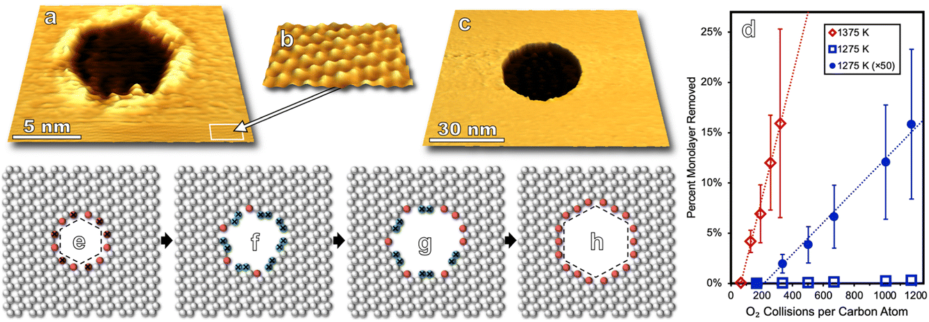 | ||
| Fig. 1 (a) STM topography (1.1 V, 0.6 nA) of a hexagonal etch pit on HOPG following 0.4 eV O2 exposure at 1275 K is shown. (b) Individual graphene unit cells are visible in (a) and magnified in a cutout region to demonstrate that etch pits align with the underlying lattice direction. (c) Annealing at 1375 with 0.4 eV O2 exposure yields isotropic etching of HOPG layers resulting in circular pits as seen in STM imaging (0.3 V, 0.6 nA). (d) Successive STM imaging with increasing 0.4 eV O2 exposure results in a linear increase in the surface reactivity of HOPG for surface temperatures of 1275 and 1375 K despite a marked increase in defect/edge sites with further reactivity. The 1275 K reactivity data is replotted with ×50 magnification to show detail. (e–h) The mechanism for anisotropic ablation of carbon atoms at 1275 K is roughly sketched showing that with the elimination of several red “zig-zag” carbon atoms, less stable blue “arm-chair” carbon atoms are exposed (e) which preferentially react away (f and g) preserving the hexagonal motif of the etch pit (h). | ||
In addition to visualizing characteristic morphological features, measurements can be made over many nanoscopic areas with increasing exposure to non-equilibrium fluxes of O2. Such statistical experiments enable the quantification of reaction rates, an example of which is seen in Fig. 1d which shows the carbon ablation rate increases with higher surface temperature (1275 to 1375 K) for incident 0.4 eV O2, but then decreases at higher temperature (1475 K). The desorption of O atoms from graphene leads to this non-Arrhenius behavior.23 Note that both reaction curves are linear in Fig. 1d. This linearity indicates that reactivity scales with 0.4 eV O2 flux. Reactivity does not scale with the concentration of defect sites which grows as the circumference of etch pits increases. At a molecular level, these observations align with a model in which O2 adsorbs at an arbitrary surface site, dissociates, and then O atoms diffuse on the surface until finding a reactive site.
Pristine graphite surfaces essentially devoid of reactive sites require an induction period or nucleation phase for reactivity to kick off, as seen in Fig. 1d. This nucleation phase can be shortened by ion sputtering, increasing the kinetic energy of incident O2, or choosing a less pristine grade of HOPG.22,23 Nanoscopic morphology for each of these approaches can be tracked via scanning probe providing an atomistic view of how defects in passivating surfaces nucleate and lead to measurable macroscopic reaction rates.
Guided by studies of molecular oxygen scattering on HOPG, ion sputtering was used to nucleate defect sites on epitaxial graphene on Ru(0001) before annealing the interface with varying fluxes of molecular oxygen (Fig. 2a). Annealing the sputtered surface at 820 K for 100 s while exposed to 10 langmuir of O2 yielded a surface with a lower defect density than before annealing (Fig. 2b). This illustrates how the dynamic equilibrium between bulk carbon in the ruthenium crystal and epitaxial graphene enable self-healing of the interface in extreme environments. Meanwhile, following the same procedure only dosing 10 langmuir over 10 s (higher flux but same dose) graphene is seen to be etched away in some areas leaving bare ruthenium terraces (Fig. 2c). This demonstrates that varying flux, but not the overall dose, can lead to different kinetically driven morphological outcomes in the initial oxidation of graphene on Ru(0001). Existing domains of monolayer graphene seen after this faster exposure also have a lower defect density than the sputtered surface, indicating that not every sputtered defect successfully nucleated oxidative carbon ablation. The edges of these monolayer graphene domains align with the moiré pattern (Fig. 2c) and the lattice direction of the Ru(0001) crystal which is given by 2 × 2 adsorbed oxygen superlattices on the bare Ru(0001) lattice indicating preferential lattice etching similar to that seen in Fig. 1 on the HOPG surface. Protrusions on the bare ruthenium surface likely correspond to ruthenium oxide clusters that form at elevated temperatures45 indicating that not all surface bound oxygen atoms are available to diffuse to reactive graphene sites.
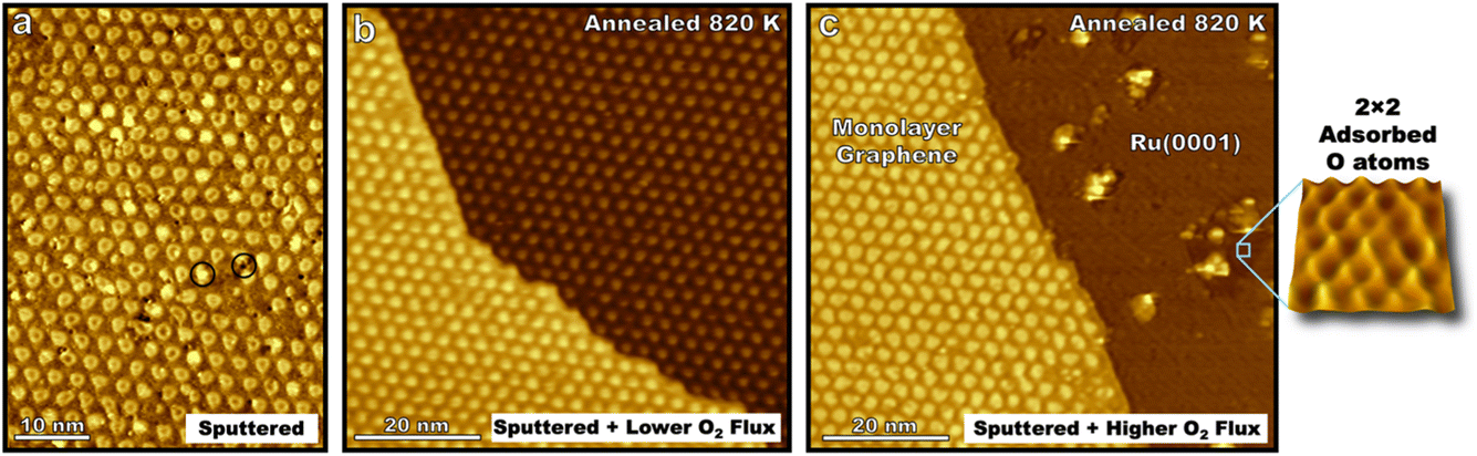 | ||
| Fig. 2 STM images (−1.5 V, −250 pA, 300 K) show the graphene/Ru(0001) interface after Ar+ sputtering to induce defects that appear as both bright and dark spots (see encircled examples) at various sites on the moiré lattice and subsequent annealing with O2 overpressures. Sputtering the surface with 0.5 keV Ar+ (60 s, 0.1 μA) yielded surface defects seen in (a) at a density of 0.036 defects per nm2. After the same sputtering procedure, in separate experiments G/Ru(0001) was exposed to 10 langmuir of O2 at 820 K over either 1000 s (b) or 100 s (c). A lower O2 flux (b, 0.01 langmuir per s) resulted in largely defect-free G/Ru(0001). A higher O2 flux (c, 0.1 langmuir per s) resulted in the erosion of graphene in (c). Note that the graphene edge aligns with the lattice direction of moiré pattern. Bare ruthenium terraces showed small islands of 2 × 2 adsorbed oxygen which appear in STM images as darker regions due to the lower DOS of adsorbed oxygen atoms compared to ruthenium atoms. A magnified view of the 2 × 2 oxide pattern is shown. | ||
The results demonstrate the self-healing properties of epitaxial graphene at 820 K on ruthenium in the initial stages of oxidation in extreme environments, a property which is not seen for many-layered graphitic systems. Molecular oxygen readily adsorbs on the bare Ru(0001) surface, so like HOPG surfaces, the kinetics of carbon etching will be strongly affected by the concentration of on-surface oxygen species. However, forming a complete kinetic model for the oxidation of the graphene–ruthenium interface at elevated temperatures poses a formidable challenge with many variables including surface temperature, the concentration and mobility of carbon in the ruthenium crystal, surface coverage of graphene, and the concentration and mobility of oxygen in various states on the moiré lattice, Ru(0001), and newly formed ruthenium-oxide clusters.
Site-specific moiré templated oxidation of epitaxial graphene by O(3P)
In this section, we present results for the oxidation of epitaxial graphene on ruthenium by O(3P). In doing so, we introduce STM visualization of surfaces following nonthermal O(3P) fluxes generated by a custom-built water-cooled radio frequency blown-glass molecular beam nozzle. O(1D) is not expected to be a significant product given considerable quenching in a neat O2 beam,44 so virtually all atomic species impinging on the surface are O(3P). We thus have an angle, energy, and quantum state specific experiment which is amenable to ongoing theoretical collaborations, and results provide insight to the deterministic placement of atomic defects on graphene interfaces by means of moiré templated oxidation.STM visualization shows the characteristic moiré pattern (Fig. 3) arising from the lattice mismatch between the ruthenium and graphene unit cells. While the actual moiré pattern is a gargantuan 25 × 25 supercell of graphene positioned on 23 × 23 Ru atoms,35 we refer to a simplified moiré unit cell in our paper. A model of the simplified unit cell is depicted in Fig. 3a and is traced onto an STM image in Fig. 3b. Three regions are labeled: atop, HCP, and FCC referring to the atomic stacking at different loci on the unit cell.
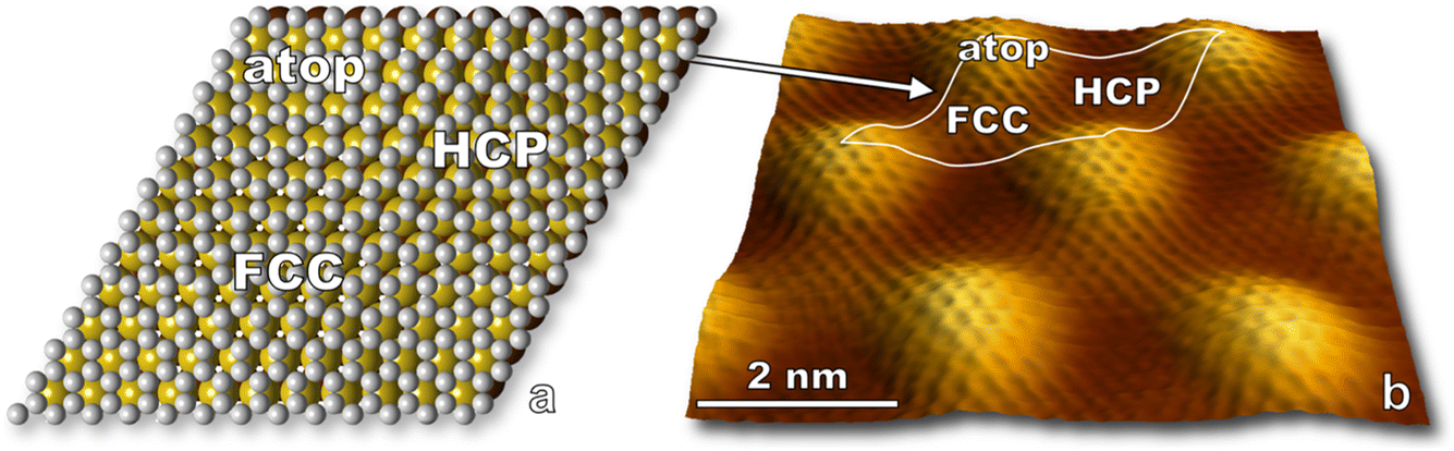 | ||
| Fig. 3 (a) A sketch of epitaxial graphene on the first two layers of Ru(0001) illustrates three atomic packing motifs in the G/Ru(0001) moiré pattern. Atop: the graphene unit cell is centered over a top layer Ru atom. HCP: the graphene unit cell is centered over a second layer Ru atom. FCC: the graphene unit cell is directly over a void in both Ru layers. (b) Atomic resolution STM topography (10 mV, 2.3 nA) shows G/Ru(0001)'s 3 nm periodic moiré pattern, and individual graphene unit cells are clearly visible. A simplified moiré unit cell is outlined in white over the STM image with regions of interest labeled. | ||
Regions on the moiré pattern experience different reactivity upon exposure to O(3P) as seen in Fig. 4. Directly after reaction, O atoms are observed to preferentially populate FCC sites over HCP in a 3![[thin space (1/6-em)]](https://www.rsc.org/images/entities/char_2009.gif) :1 ratio. This 3:1 ratio highlights the fact that non-equilibrium reaction dynamics are being observed, as the energy difference in oxygen adsorption sites between FCC and HCP regions (0.05 eV) would predict an approximate 6:1 partitioning between FCC and HCP regions at room temperature.36 Significant barriers to diffusion in both FCC and HCP regions (1.2 and 0.9 eV respectively)36 enable visualization of nonthermal distributions of O atoms after molecular beam exposure.
:1 ratio. This 3:1 ratio highlights the fact that non-equilibrium reaction dynamics are being observed, as the energy difference in oxygen adsorption sites between FCC and HCP regions (0.05 eV) would predict an approximate 6:1 partitioning between FCC and HCP regions at room temperature.36 Significant barriers to diffusion in both FCC and HCP regions (1.2 and 0.9 eV respectively)36 enable visualization of nonthermal distributions of O atoms after molecular beam exposure.
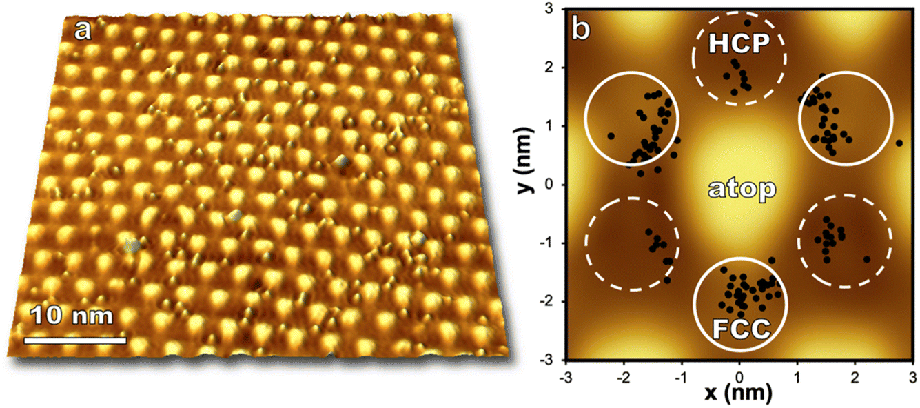 | ||
| Fig. 4 (a) STM topography (−1.5 V, −250 pA) shows individual oxygen atoms on the epitaxial graphene moiré pattern after exposure to atomic O (0.085 O per nm2, ∼0.04 eV) impinging normal to a 300 K surface. (b) The location of each O atom on the moiré superlattice in (a) is plotted in relation to its closest atop region. Reactivity is seen to vary by location on the moiré unit cell i.e., FCC > HCP ≫ atop regions. FCC and HCP regions of the moiré pattern are labeled with solid and dashed lines respectively. | ||
Computational work indicates oxygen may bind as enolate species on epitaxial graphene grown on transition metals,46 and a DFT/STM study of graphene on Ru(0001) indicated that an enolate is formed for FCC and HCP regions of the graphene/Ru(0001) interface while an epoxide species is energetically favorable for atop regions.36 The moiré pattern is highly corrugated and provides a wide offering of binding locations for atomic oxygen, even within individual HCP and FCC regions. Analysis of just one STM image shown in Fig. 4 demonstrates that even in the low coverage regime oxygen is distributed over a range of binding sites on the moiré pattern. However, oxygen atoms are seen to avoid atop regions and the zones between HCP and FCC sites. With increasing coverage (up to 1.3 O per nm2) atop regions remain unreacted, but the ratio of HCP versus FCC bound oxygen atoms approaches 1:1 well below monolayer coverage.
The role pre-adsorbed oxygen atoms play in promoting nonreactive scattering and the effects of spin-forbidden reaction dynamics of O(3P) impinging on graphene are open questions for this chemical system.1,47 Taken together with the rich spatial data available via STM, these questions show that moiré templated oxidation of graphene opens a new regime of studying on-surface chemical dynamics and poses worthwhile theoretical challenges for examining highly corrugated potential energy surfaces heretofore investigated through the presence of steps, kinks, vacancies, or heteroatoms in model surfaces.
Enhanced monolayer versus bilayer graphene reactivity with O(3P)
While monolayer graphene experiences strong electronic coupling to the underlying ruthenium substrate, the top sheet of bilayer graphene on Ru(0001) has an electronic structure more similar to that of freestanding graphene regaining the characteristic Dirac cones of isolated graphene.41,43 The 3 nm moiré pattern seen on bilayer graphene arises from lattice mismatch between the bottom graphene sheet and the underlying Ru(0001). The stacking of the two graphene sheets alternates between AA and AB over a larger 21.5 nm moiré pattern which arises from a 1.2% stretching of the bottom graphene layer in comparison to the more free-standing top layer.42 As described, the stacking of the top graphene sheet on the bottom sheet (AA vs. AB) cannot be determined by its 3 nm moiré pattern, so we refer to the 3 nm periodic raised areas of the bilayer as “mounds” not “atop regions” to avoid confusion. (For monolayer graphene “atop” refers to a graphene unit cell sitting “atop” of a ruthenium atom as seen in Fig. 3a). The 3 nm periodicity of monolayer and bilayer epitaxial graphene is depicted in Fig. 5 along with concurrently measured conductance mapping. A clear difference in electronic character between monolayer and bilayer graphene is visualized, similar in scale to the corrugation between FCC/HCP and atop regions of the monolayer interface.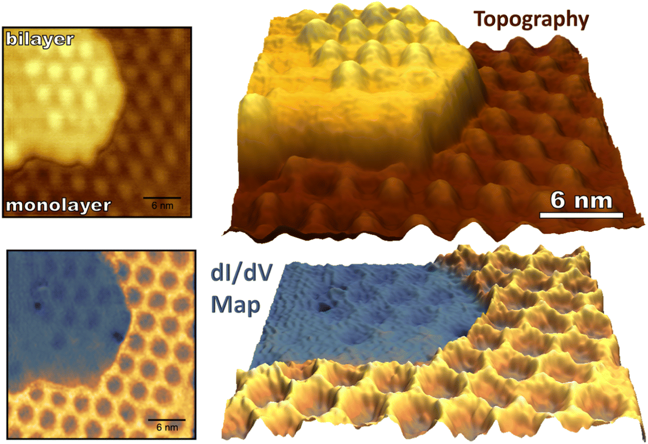 | ||
| Fig. 5 Topography (top) and conductance mapping (bottom) of pristine monolayer and bilayer graphene on Ru(0001) is shown (−1.5 V, −250 pA). The bias was modulated with an amplitude of 200 mV to generate the dI/dV map. Note that atop regions of the single-layer graphene moiré pattern and the entirety of the bilayer graphene show lower conductance than the HCP and FCC regions of the G/Ru(0001) moiré pattern. | ||
Upon exposure to O(3P), preferential adsorption is observed for monolayer graphene on Ru(0001) in comparison to bilayer graphene. This is clearly seen in Fig. 6a–c where monolayer and bilayer graphene have both been simultaneously dosed with atomic oxygen impinging normal to a 258 K surface. Bilayer oxygen coverage (0.13 O per nm2) is only 14% that of monolayer coverage (0.91 O per nm2). Spin-forbidden reaction dynamics result in the sticking probability of O(3P) being ∼10% on graphitic surfaces for what should be a nearly barrierless reaction1—and this new experiment provides a striking side-by-side comparison of O(3P) reactivity for both more freestanding (sp2 hybridized) and more tightly bound graphene.
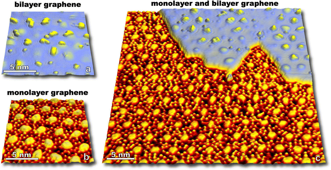 | ||
| Fig. 6 STM images showing monolayer (a, 1.5 V, 250 pA, 230 K) and bilayer graphene (b, −1.5 V, −250 pA, 230 K) on Ru(0001) after dosing O(3P) onto the surface at 258 K. An STM image with both monolayer and bilayer coverage (c) shows over 1200 O atoms on the monolayer graphene in HCP/FCC regions of the moiré lattice; while 63 O atoms are sparsely populated on both mounded and lower regions of the bilayer moiré lattice in this STM image. Monolayer and bilayer graphene have coverages of 0.91 O per nm2 and 0.13 O per nm2, respectively. Sticking of O(3P) on bilayer graphene is ∼14% that seen on monolayer graphene on Ru(0001). | ||
Not only do O atoms adsorb at a lower rate on bilayer graphene on Ru(0001), but the oxygen atoms also have different site-specificity in their binding on the 3 nm moiré pattern. Seen in Fig. 6, oxygen atoms bind at HCP and FCC sights even at higher coverage (0.91 O per nm2) on monolayer graphene. However, on the bilayer graphene O atoms tend to bind on the mounded regions of the moiré lattice (Fig. 7) in contrast to the distribution of O atoms shown in Fig. 4 where O atoms were found in lower regions of the moiré pattern. Layer-dependent site-specificity in adatom placement opens another avenue for tunable functionalization of moiré templated 2D materials. Ongoing theoretical collaboration will provide insight to whether this preference in binding is driven by lattice strain from spatial corrugation at these atop regions, or the binding geometry of atomic oxygen species, and the role spin-forbidden reaction dynamics play in O(3P) adsorption on epitaxial graphene on ruthenium.
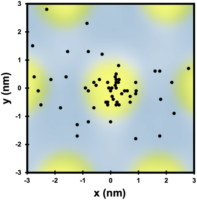 | ||
| Fig. 7 The location of each O atom on the moiré superlattice of the bilayer graphene in Fig. 6c is plotted in relation to its closest mounded region. Unlike O atom placement on monolayer graphene on Ru(0001), O atoms are found in mounded regions of the bilayer moiré lattice. Overall site specificity is reduced on the bilayer graphene. | ||
Conclusion
We have demonstrated that the combination of molecular beams with in situ STM visualization can enable a detailed spatiotemporal understanding of the oxidation of single- double- and many-layered graphitic surfaces. Insights gained at the atomic-, nano-, and meso-length scales would be lost if traditional ensemble techniques which monitor volatile products were solely utilized. In particular, on-surface dynamics recognized in this paper feature time-evolving interfaces and spatiotemporal correlations in reactivity which are well-captured by real-time or time-lapse sequential atomic visualization. We have demonstrated how chemical dynamics can be strongly affected by local surface morphology through examples of structural inhomogeneities enhancing the ablation of graphite and moiré site-specific reactivity of O(3P) adsorption on epitaxial graphene. The results promise a route to tunably-oxidized moiré-templated 2D materials with the placement of oxygen adatoms and reactivity of the material strongly affected by the number of graphene layers on Ru(0001). Self-healing properties of epitaxial graphene in certain oxidative regimes and reduced reactivity of bilayer versus monolayer graphene with atomic oxygen exposure provide insights for anticorrosion applications.Taken together, these experiments present an exciting outlook for the examination of condensed-phase scattering in which surface morphology and impact conditions of incident gas species serve as parameters to control outcomes ranging from site-specificity in adsorption to overall sticking probability. Such investigations enable a direct and spatially rich complement to traditional surface scattering experiments and hold notable promise as a new direction in molecular scattering.
Author contributions
R. E., T. G., and B. W. researched HOPG ablation. J. W. examined oxidation of monolayer and bilayer graphene on ruthenium and prepared the manuscript. S. J. S. led experiment ideation for all projects, participated in instrument and experimental design, data analysis, manuscript preparation, and provided thoughtful mentoring to all authors.Conflicts of interest
There are no conflicts to declare.Acknowledgements
The authors gratefully acknowledge support from the Air Force Office of Scientific Research Grant FA9550-19-1-0324, with focus on the dynamics of energetic gas-surface interactions and the AFOSR-DURIP program grant FA9550-23-1-0528. The National Science Foundation Grant CHE-2313365, with focus on spatiotemporal interfacial chemical kinetics is also gratefully acknowledged as well as infrastructure support from the NSF-Materials Research Science and Engineering Center at the University of Chicago grant DMR-2011854.References
- Z. Zhao, Y. Wang, X. Yang, J. Quan, B. C. Krüger, P. Stoicescu, R. Nieman, D. J. Auerbach, A. M. Wodtke, H. Guo and G. B. Park, Nat. Chem., 2023, 15, 1006–1011 CrossRef CAS PubMed.
- M. J. Abplanalp, S. Góbi and R. I. Kaiser, Phys. Chem. Chem. Phys., 2019, 21, 5378–5393 RSC.
- L. Romm, O. Citri, R. Kosloff and M. Asscher, J. Chem. Phys., 2000, 112, 8221–8224 CrossRef CAS.
- L. Romm, G. Katz, R. Kosloff and M. Asscher, J. Phys. Chem. B, 1997, 101, 2213–2217 CrossRef CAS.
- R. C. Egeberg, J. H. Larsen and I. Chorkendorff, Phys. Chem. Chem. Phys., 2001, 3, 2007–2011 RSC.
- S. Dahl, A. Logadottir, R. C. Egeberg, J. H. Larsen, I. Chorkendorff, E. Törnqvist and J. K. Nørskov, Phys. Rev. Lett., 1999, 83, 1814–1817 CrossRef.
- S. Dahl, E. Törnqvist and I. Chorkendorff, J. Catal., 2000, 192, 381–390 CrossRef CAS.
- H. Mortensen, E. Jensen, L. Diekhöner, A. Baurichter, A. C. Luntz and V. V. Petrunin, J. Chem. Phys., 2003, 118, 11200–11209 CrossRef CAS.
- L. Diekhöner, H. Mortensen, A. Baurichter, E. Jensen, V. V. Petrunin and A. C. Luntz, J. Chem. Phys., 2001, 115, 9028–9035 CrossRef.
- L. Diekhöner, L. Hornekær, H. Mortensen, E. Jensen, A. Baurichter, V. V. Petrunin and A. C. Luntz, J. Chem. Phys., 2002, 117, 5018–5030 CrossRef.
- D. C. Papageorgopoulos, B. Berenbak, M. Verwoest, B. Riedmu, S. Stolte and A. W. Kleyn, Chem. Phys. Lett., 1999, 305, 401–407 CrossRef CAS.
- X. Zhao, G. M. Nathanson and G. G. Andersson, J. Phys. Chem. A, 2020, 124, 11102–11110 CrossRef CAS PubMed.
- M. J. Roman, A. G. Knight, D. R. Moon, P. D. Lane, S. J. Greaves, M. L. Costen and K. G. McKendrick, J. Chem. Phys., 2023, 158, 244704 CrossRef CAS PubMed.
- A. C. Dorst, F. Güthoff, D. Schauermann, A. M. Wodtke, D. R. Killelea and T. Schäfer, Phys. Chem. Chem. Phys., 2022, 24, 26421–26427 RSC.
- S. Brown, J. D. Sayler and S. J. Sibener, J. Phys. Chem. C, 2021, 125, 24406–24412 CrossRef CAS.
- J. D. Sayler, S. Brown and S. J. Sibener, J. Phys. Chem. C, 2019, 123, 26932–26938 CrossRef CAS.
- B. Wiggins, L. G. Avila-Bront, R. Edel and S. J. Sibener, J. Phys. Chem. C, 2016, 120, 8191–8197 CrossRef CAS.
- J. Wagner, T. Grabnic and S. J. Sibener, J. Phys. Chem. C, 2022, 126, 18333–18342 CrossRef CAS PubMed.
- Y. Wang and H. Guo, J. Phys. Chem. C, 2023, 127, 4079–4086 CrossRef CAS.
- W. Dou and J. E. Subotnik, J. Phys. Chem. A, 2020, 124, 757–771 CrossRef CAS PubMed.
- M. Majumder, K. D. Gibson, S. J. Sibener and W. L. Hase, J. Phys. Chem. C, 2018, 122, 16048–16059 CrossRef CAS.
- S. Hariharan, M. Majumder, R. Edel, T. Grabnic, S. J. Sibener and W. L. Hase, J. Phys. Chem. C, 2018, 122, 29368–29379 CrossRef CAS.
- R. Edel, T. Grabnic, B. Wiggins and S. J. Sibener, J. Phys. Chem. C, 2018, 122, 14706–14713 CrossRef CAS.
- S. E. Kim, F. Mujid, A. Rai, F. Eriksson, J. Suh, P. Poddar, A. Ray, C. Park, E. Fransson, Y. Zhong, D. A. Muller, P. Erhart, D. G. Cahill and J. Park, Nature, 2021, 597, 660–665 CrossRef CAS PubMed.
- Y. Kim and J. Cho, Appl. Sci., 2019, 9, 3323 CrossRef CAS.
- F. Stevens, L. A. Kolodny and T. P. Beebe, J. Phys. Chem. B, 1998, 102, 10799–10804 CrossRef CAS.
- X. Chu and L. D. Schmidt, Surf. Sci., 1992, 268, 325–332 CrossRef CAS.
- V. J. Murray, E. J. Smoll and T. K. Minton, J. Phys. Chem. C, 2018, 122, 6602–6617 CrossRef CAS.
- V. J. Murray, B. C. Marshall, P. J. Woodburn and T. K. Minton, J. Phys. Chem. C, 2015, 119, 14780–14796 CrossRef CAS.
- H. Zhang, Q. Fu, Y. Cui, D. Tan and X. Bao, J. Phys. Chem. C, 2009, 113, 8296–8301 CrossRef CAS.
- A. Dong, Q. Fu, M. Wei, Y. Liu, Y. Ning, F. Yang, H. Bluhm and X. Bao, Surf. Sci., 2015, 634, 37–43 CrossRef CAS.
- P. Sutter, J. T. Sadowski and E. A. Sutter, J. Am. Chem. Soc., 2010, 132, 8175–8179 CrossRef CAS.
- E. Starodub, N. C. Bartelt and K. F. McCarty, J. Phys. Chem. C, 2010, 114, 5134–5140 CrossRef CAS.
- K. F. McCarty, P. J. Feibelman, E. Loginova and N. C. Bartelt, Carbon, 2009, 47, 1806–1813 CrossRef CAS.
- D. Martoccia, P. R. Willmott, T. Brugger, M. Björck, S. Günther, C. M. Schlepütz, A. Cervellino, S. A. Pauli, B. D. Patterson, S. Marchini, J. Wintterlin, W. Moritz and T. Greber, Phys. Rev. Lett., 2008, 101, 126102 CrossRef CAS.
- Z. Novotny, M.-T. Nguyen, F. P. Netzer, V.-A. Glezakou, R. Rousseau and Z. Dohnálek, J. Am. Chem. Soc., 2018, 140, 5102–5109 CrossRef CAS.
- M. Kögl, P. Soubelet, M. Brotons-Gisbert, A. V. Stier, B. D. Gerardot and J. J. Finley, npj 2D Mater. Appl., 2023, 7, 32 CrossRef.
- K. Donner and P. Jakob, J. Chem. Phys., 2009, 131, 164701 CrossRef PubMed.
- D. M. Kennes, M. Claassen, L. Xian, A. Georges, A. J. Millis, J. Hone, C. R. Dean, D. N. Basov, A. N. Pasupathy and A. Rubio, Nat. Phys., 2021, 17, 155–163 Search PubMed.
- L. C. Bassett, A. Alkauskas, A. L. Exarhos and K.-M. C. Fu, Nanophotonics, 2019, 8, 1867–1888 Search PubMed.
- J. Halle, N. Néel and J. Kröger, J. Phys. Chem. Lett., 2021, 12, 6889–6894 Search PubMed.
- Y. Que, W. Xiao, X. Fei, H. Chen, L. Huang, S. X. Du and H.-J. Gao, Appl. Phys. Lett., 2014, 104, 093110 CrossRef.
- P. Sutter, M. S. Hybertsen, J. T. Sadowski and E. Sutter, Nano Lett., 2009, 9, 2654–2660 CrossRef CAS PubMed.
- S. J. Sibener, R. J. Buss, C. Y. Ng and Y. T. Lee, Rev. Sci. Instrum., 1980, 51, 167–182 CrossRef CAS.
- B. Herd and H. Over, Surf. Sci., 2014, 622, 24–34 CrossRef CAS.
- J. Jung, H. Lim, J. Oh and Y. Kim, J. Am. Chem. Soc., 2014, 136, 8528–8531 CrossRef CAS PubMed.
- B. Jayee, R. Nieman, T. K. Minton, W. L. Hase and H. Guo, J. Phys. Chem. C, 2021, 125, 9795–9808 CrossRef CAS.
| This journal is © The Royal Society of Chemistry 2024 |